EP3909866B1 - Abfüllvorrichtung, insbesondere nahrungsmittelabfüllvorrichtung, zu einem dosieren eines vorgegebenen gewichts und/oder volumens eines zu dosierenden füllguts, system mit der vorrichtung und verfahren - Google Patents
Abfüllvorrichtung, insbesondere nahrungsmittelabfüllvorrichtung, zu einem dosieren eines vorgegebenen gewichts und/oder volumens eines zu dosierenden füllguts, system mit der vorrichtung und verfahren Download PDFInfo
- Publication number
- EP3909866B1 EP3909866B1 EP21173223.5A EP21173223A EP3909866B1 EP 3909866 B1 EP3909866 B1 EP 3909866B1 EP 21173223 A EP21173223 A EP 21173223A EP 3909866 B1 EP3909866 B1 EP 3909866B1
- Authority
- EP
- European Patent Office
- Prior art keywords
- filling
- dosing
- filling material
- volume
- metering
- Prior art date
- Legal status (The legal status is an assumption and is not a legal conclusion. Google has not performed a legal analysis and makes no representation as to the accuracy of the status listed.)
- Active
Links
Images




Classifications
-
- B—PERFORMING OPERATIONS; TRANSPORTING
- B65—CONVEYING; PACKING; STORING; HANDLING THIN OR FILAMENTARY MATERIAL
- B65B—MACHINES, APPARATUS OR DEVICES FOR, OR METHODS OF, PACKAGING ARTICLES OR MATERIALS; UNPACKING
- B65B1/00—Packaging fluent solid material, e.g. powders, granular or loose fibrous material, loose masses of small articles, in individual containers or receptacles, e.g. bags, sacks, boxes, cartons, cans, or jars
- B65B1/04—Methods of, or means for, filling the material into the containers or receptacles
- B65B1/10—Methods of, or means for, filling the material into the containers or receptacles by rotary feeders
-
- B—PERFORMING OPERATIONS; TRANSPORTING
- B65—CONVEYING; PACKING; STORING; HANDLING THIN OR FILAMENTARY MATERIAL
- B65B—MACHINES, APPARATUS OR DEVICES FOR, OR METHODS OF, PACKAGING ARTICLES OR MATERIALS; UNPACKING
- B65B1/00—Packaging fluent solid material, e.g. powders, granular or loose fibrous material, loose masses of small articles, in individual containers or receptacles, e.g. bags, sacks, boxes, cartons, cans, or jars
- B65B1/30—Devices or methods for controlling or determining the quantity or quality or the material fed or filled
- B65B1/32—Devices or methods for controlling or determining the quantity or quality or the material fed or filled by weighing
-
- B—PERFORMING OPERATIONS; TRANSPORTING
- B65—CONVEYING; PACKING; STORING; HANDLING THIN OR FILAMENTARY MATERIAL
- B65B—MACHINES, APPARATUS OR DEVICES FOR, OR METHODS OF, PACKAGING ARTICLES OR MATERIALS; UNPACKING
- B65B1/00—Packaging fluent solid material, e.g. powders, granular or loose fibrous material, loose masses of small articles, in individual containers or receptacles, e.g. bags, sacks, boxes, cartons, cans, or jars
- B65B1/30—Devices or methods for controlling or determining the quantity or quality or the material fed or filled
- B65B1/36—Devices or methods for controlling or determining the quantity or quality or the material fed or filled by volumetric devices or methods
- B65B1/363—Devices or methods for controlling or determining the quantity or quality or the material fed or filled by volumetric devices or methods with measuring pockets moving in an endless path
- B65B1/366—Devices or methods for controlling or determining the quantity or quality or the material fed or filled by volumetric devices or methods with measuring pockets moving in an endless path about a horizontal axis of symmetry
-
- B—PERFORMING OPERATIONS; TRANSPORTING
- B65—CONVEYING; PACKING; STORING; HANDLING THIN OR FILAMENTARY MATERIAL
- B65B—MACHINES, APPARATUS OR DEVICES FOR, OR METHODS OF, PACKAGING ARTICLES OR MATERIALS; UNPACKING
- B65B3/00—Packaging plastic material, semiliquids, liquids or mixed solids and liquids, in individual containers or receptacles, e.g. bags, sacks, boxes, cartons, cans, or jars
- B65B3/04—Methods of, or means for, filling the material into the containers or receptacles
Definitions
- a filling device in particular a food filling device, for dosing a predetermined weight and/or volume of a filling material to be dosed is already known, the filling device having a collection container which is provided for the purpose that the filling material to be dosed is collected in it, a dosing element which is dosing of the filling material is provided for removing a defined volume of the filling material from the collection container, and a storage module which supports the dosing element movably.
- the invention is based on a filling device, in particular a food filling device, for dosing a predetermined weight and/or volume of a filling material to be dosed, with a collection container which is provided for the purpose that the filling material to be dosed is collected therein, with a dosing element which, in particular is designed as a dosing spoon, which is provided for dosing the filling material to remove a defined volume of the filling material from the collection container, and with a storage module that supports the dosing element movably. It is proposed that the storage module has at least one linear bearing, by means of which the dosing element can be adjusted between a removal position and a transfer position.
- a “filling device” should preferably be understood to mean a device which is provided for dispensing a product, preferably a product, metered into at least one container to be filled, preferably into a plurality of containers to be filled.
- the filling device is preferably provided for filling a plurality of containers at the same time with a defined weight and/or volume of a filling material.
- a “food filling device” should preferably be understood to mean a filling device which is intended to fill a foodstuff trained filling material dosed into containers to be filled.
- a “filling material to be metered” should preferably be understood to mean a bulk material, that is to say preferably a powdery, granular and/or lumpy mixture which is in a pourable form.
- the filling material to be metered can preferably have a moisture content.
- a "collecting container” should preferably be understood to mean a container in which the filling material to be dosed can be caught, preferably collected.
- the filling material is preferably arranged in the collection container for metered removal, that is to say collected.
- the collection container has a concave inner contour that forms a receiving volume of the collection container, in which the filling material is arranged for metered removal.
- a “dosing element” should preferably be understood to mean an element that spans a dosing volume that is intended for dosing a filling material to be filled with the filling material.
- the dosing element preferably has a convex dosing area that delimits the dosing volume.
- the convex dosing area is designed as a recess.
- the dosing element is preferably designed as a dosing spoon.
- a "dosing spoon” should preferably be understood to mean an element which has a connecting web and a spoon shell which is arranged at one end of the connecting web and which preferably forms the convex dosing area.
- a “storage module” should preferably be understood to mean a module that is provided for the movable storage of at least one element, preferably the dosing element.
- the storage module is preferably provided for the purpose of storing an element to be stored, such as preferably the dosing element, so that it can be displaced in a rotary and/or linear manner.
- the dosing element for removing the defined volume of the filling material from the collection container is intended to be moved by means of the storage module through a receiving volume of the collection container.
- a “receiving volume” should preferably be understood to mean a volume that is spanned by the collecting container, in particular a concave inner contour of the receiving container.
- the receiving volume preferably defines a space in which the filling material can be collected.
- to be moved through the receiving volume is meant preferably be understood that at least one convex dosing area of the dosing element is guided through the collection container in such a way that the filling material collected in the collection container can be received by the dosing area.
- the dosing element is preferably guided in a linear and/or rotational movement through the receiving volume of the collection container.
- the convex dosing area of the dosing element is preferably guided in a linear and/or rotational movement through the receiving volume of the collection container.
- the dosing element is particularly preferably moved in a pivoting movement through the receiving volume of the collection container.
- the dosing element is guided through the receiving volume of the collection container in a linear movement or in a combined linear and rotational movement.
- the filling material can be removed from the collection container in a particularly simple manner and the dosing device can be designed in a particularly simple manner.
- the storage module forms an axis of rotation and is intended to rotate the dosing element about the axis of rotation in order to remove the defined volume of the filling material from the collection container.
- the dosing element can be stored particularly advantageously by means of the storage device for removing the filling material.
- the storage module is provided for rotating the dosing element about the axis of rotation in order to transfer the removed filling material to a container to be filled.
- the filling material can be transferred from the dosing element in a particularly simple manner.
- a “linear bearing” should preferably be understood to mean a bearing which comprises at least two bearing elements which can be displaced linearly with respect to one another along a bearing axis.
- a first bearing element of the linear bearing is preferably designed as a linear bearing rail.
- a “linear bearing rail” is to be understood in particular as a linear guide element which is intended to form a bearing track, preferably a straight bearing axis, along which another Element is linearly displaceable on the linear bearing rail.
- a linear bearing rail is provided for a guide element to be connected to it in a form-fitting and/or non-positive manner, the guide element having a degree of freedom relative to the linear bearing rail at least along one path, in particular along the bearing axis.
- a second bearing element of the linear bearing can preferably be designed as a guide element.
- the second bearing element is designed to correspond to the first bearing element and is intended to be movably mounted relative to the first bearing element.
- the second bearing element is preferably mounted so that it can move relative to the first bearing element along the bearing track.
- the second bearing element is preferably embodied as a bearing carriage, which is movably mounted relative to the first bearing element, embodied as a linear bearing rail.
- the second bearing element preferably has a base body and at least one guide element which is connected to the base body and is intended to be connected to the first bearing element for the movable mounting of the second bearing element.
- a “removal position” should preferably be understood as an axial positioning of the dosing element on the linear bearing, in which the dosing element is positioned axially such that it can be guided through the collection container in order to remove the filling material from the collection container.
- a “transfer position” should preferably be understood as an axial positioning of the dosing element on the linear bearing, in which the dosing element is positioned axially in such a way that it can move the received filling material by a defined movement, preferably a rotation, to a container to be filled. As a result, the dosing element can be adjusted particularly easily between the removal position and the transfer position.
- the filling device has a stripping element which is provided before the filling material is transferred in order to reduce the filling material arranged in the dosing element to the predetermined volume.
- a “wiping element” should preferably be understood to mean an element which is intended to wipe off excess filling material, ie filling material exceeding a maximum filling quantity, ie removing it from the dosing element and preferably bringing it back into the collection container.
- the filling material taken up by the dosing element is always reduced to the same defined volume by the stripping element by moving past the stripping element will. As a result, a precise and consistent removal of a defined volume of filling material can be achieved in a particularly advantageous manner by means of the dosing element.
- the storage device is provided to guide the dosing element past the stripping element during an adjustment from the removal position into the transfer position in order to strip off and/or compact the filling material arranged in the dosing element.
- Passing the stripping element should preferably be understood to mean that the dosing element is guided along the stripping element at least with its dosing area, with the stripping element preferably lying against an upper edge of the dosing area.
- the dosing element is preferably guided past the stripping element in such a way that the stripping element is arranged exactly at an upper end of the dosing volume and thus delimits the dosing volume.
- To scrape off and/or to compact is preferably to be understood as meaning that the scraping element scrapes at least part of the filling material that protrudes beyond the metering volume, i.e. an upper edge of the metering area, i.e. removes it from the metering element and/or also partially into it pushes in the dosing volume of the dosing area in order to compress the filling material arranged in the dosing volume of the dosing area.
- the filling material arranged in the dosing element can be set to a desired volume and/or weight in a particularly simple and precise manner.
- the filling device has at least one transfer element, via which the filling material to be dosed can be guided from the dosing element directly to a container to be filled in a transfer position of the dosing element.
- a "transfer element” should preferably be understood to mean an element through or over which a filling material can be guided from a first end to a second end.
- the filling material is preferably moved through the transfer element by gravity.
- the transfer element is preferably designed as a tubular element through which the filling material can fall.
- the transfer element is preferably designed as a downpipe.
- the transfer element designed as a transfer tube is preferably aligned vertically, so that a filling material inlet and a filling material outlet are arranged one above the other.
- the transfer element is designed as an inclined channel or an inclined slide plate, over which a filling can slide from a first end to a second end.
- a “container to be filled” should preferably be understood to mean a container that is provided for safe storage and keeping the contents fresh.
- a container to be filled can be, for example, a plastic cup, a tin can, a paper cup, or another container that the person skilled in the art deems appropriate for storing a product, in particular a foodstuff.
- the dosed filling material can be guided completely from the dosing element to the container to be filled in a particularly reliable manner.
- the filling material can be guided particularly advantageously as a vertically aligned downpipe to the container to be filled.
- the collection container is designed as a trough, the inner contour of which has a uniform curvature, at least in a partial area.
- the fact that the inner contour "has a uniform curvature at least in a partial area” should preferably be understood to mean that at least 50%, preferably 75% and in a particularly advantageous embodiment over 90% of the inner contour has a uniform curvature.
- the inner contour of the collection container designed as a trough forms a semicircular shape.
- only a middle partial area of the inner contour of the collection container designed as a trough has a uniform curvature and outer areas form a smaller curvature or a straight line.
- the collection container can be designed particularly advantageously for removing the filling material by means of the dosing element.
- the filling device has a drainage device which is provided for transporting a liquid away from the collection container, with an outlet opening being arranged below a minimum scoop height of the dosing element.
- a “drainage device” should preferably be understood to mean a device through which a liquid can flow out of the collection container by gravity or can be actively sucked out of the collection container.
- Below a “minimum scoop height” should preferably be understood as a minimum height in the collection container, up to which the metering element can extend with its maximum metering area.
- “Below the minimum scoop height” should preferably be understood to mean closer to a floor, ie a level, on which the filling device is set up.
- liquid can advantageously be removed from the collection container, as a result of which the dosing element and/or other parts of the filling device cannot become clogged with liquid, which can escape from the filling material, for example.
- the dosing element and/or other parts of the filling device cannot become clogged with liquid, which can escape from the filling material, for example.
- in particular cleanliness and accuracy of the filling device can be improved.
- the filling device has at least one further dosing element, which is movably mounted parallel to the one dosing element via the storage module and is provided for dosing the filling material for removing a defined volume of the filling material from the collection container.
- a “further dosing element” should preferably be understood to mean a dosing element of the same design, which is connected via the same storage module and is preferably designed exactly the same as the first dosing element.
- the filling device can be designed particularly advantageously for filling into a plurality of containers.
- the filling device has at least one liquid dosing module, which is provided to fill the container with a liquid after filling a container to be filled with filling material by means of the dosing element, until a desired total filling volume and/or total filling weight is reached.
- a “liquid dosing module” should preferably be understood to mean a module that can add a liquid to the metered filling material in the container to be filled. A liquid is preferably injected into the container. The liquid dosing module is preferably spaced apart, that is to say spatially separated from the dosing elements and the collection container.
- the filling device can advantageously be placed in a dry area, namely dosing by means of the dosing elements and a wet area, namely the filling of liquid by means of the liquid dosing module.
- a total weight of the filling material and the liquid arranged in the container can be set particularly well.
- an advantageous separation of a dry area and a liquid area of the filling device can be achieved, whereby liquid-sensitive components, such as load cells, can advantageously be arranged outside the liquid area.
- a system with at least one filling device for filling containers to be filled with a predetermined weight and/or volume of a filling material to be dosed is proposed.
- the system preferably has a control and/or regulation unit which is intended to control the filling device.
- a “control and/or regulation unit” is to be understood in particular as a unit with at least one electronic control system.
- Control electronics should be understood to mean, in particular, a unit with a processor unit and with a memory unit and with an operating program stored in the memory unit. “Established” should be understood to mean, in particular, specially programmed and/or specially equipped.
- an object in particular the control and/or regulation unit, is set up for a specific function, in particular an adjustment of the transfer parameter, is to be understood in particular as meaning that the object fulfills this specific function in at least one application and/or operating state and/or executes. Due to the configuration of the system according to the invention, an advantageous, metered filling of a filling material into one or more containers can be achieved.
- the device according to the invention, the system according to the invention and/or the method according to the invention should/should not be limited to the application and embodiment described above.
- the device according to the invention, the system according to the invention and/or the method according to the invention can fulfill a function described herein have a number of individual elements, components and units as well as method steps that differs from a number mentioned herein.
- values lying within the specified limits should also be considered disclosed and can be used as desired.
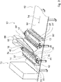
- the Figures 1 to 8 show a system according to the invention with a filling device 10.
- the system with the filling device 10 is provided for filling containers 12, 12' to be filled with a predetermined weight and/or volume of a filling material 14 to be dosed.
- the filling device 10 is designed as a food filling device.
- the filling device 10 is provided for the metered filling of a filling material 14 in the form of food.
- the filling device 10 is provided for metering a predetermined weight and/or volume of the filling material 14 to be metered.
- the contents 14 are pieces of fruit, for example.
- the filling material 14 is preferably formed by pieces of fruit, which can have a liquid content.
- the filling material 14 in the form of a powder or another lumpy bulk material.
- the system includes a product feed.
- the filling material supply is configured here as a conveyor belt, for example.
- the filling material it is also conceivable for the filling material to be supplied in a different manner that appears sensible to a person skilled in the art.
- the filling device 10 comprises two filling modules 16, 18.
- the two filling modules 16, 18 are of essentially the same design, which is why only the first filling module 16 is to be described in more detail below.
- the description of the first filling module 16 can be used to explain the second filling module 18 .
- the two filling modules 16, 18 are connected in series.
- the filling module 16 of the filling device 10 comprises a collecting container 20.
- the collecting container 20 is designed as a collecting trough.
- the collection container 20 is designed as an elongated trough.
- the collection container 20 has an inner contour which has a uniform curvature.
- the collection container 20 has a semi-circular inner contour.
- the collecting container 20 forms a receiving volume 22 .
- the inner contour of the collecting container 20 delimits the receiving volume 22.
- the collecting container 20 is provided for the purpose that the filling material 14 to be dosed is collected therein.
- the collection container 20 is elevated via an upright unit, not shown in detail.
- the stand-up unit could, for example, be formed by a frame that stands on feet.
- the filling module 16 of the filling device 10 has a dosing element 24 .
- the dosing element 24 is provided for dosing the filling material 14 in order to remove a defined volume of the filling material 14 from the collection container 20 .
- the filling device 10 includes a storage module 26 which is provided for storing the dosing element 24 .
- the dosing element 24 is movably mounted by means of the bearing module 26 .
- the dosing element 24 is movably mounted relative to the collection container 20 via the storage module 26 .
- the filling module 16 of the filling device 10 has further dosing elements 28 .
- the dosing elements 28 are arranged parallel to the dosing element 24 .
- the other dosing elements 28 are also movably mounted on the storage module 26 .
- the other dosing elements 28 are provided for dosing the filling material 14 in order to remove a defined volume of the filling material 14 from the collection container 20 .
- a defined volume of the filling material 14 can be removed from the collection container 20 at the same time.
- the first filling module 16 of the filling device 10 has ten dosing elements 24, 28 which are movably mounted by means of the storage module 26 and are provided for removing a defined volume of the filling material 14 from the collection container 20.
- the first filling module 16 it would also be conceivable for the first filling module 16 to have a different number of dosing elements 24, 28, for example four or twenty.
- the dosing elements 24, 28 are of identical design. For this reason, only one dosing element 24 will be described in more detail below. The following description of one metering element 24 can be used to explain all other metering elements 28 .
- the dosing element 24 is designed as a dosing spoon.
- the dosing element 24 designed as a dosing spoon has a convex dosing area 30 at a first end.
- the convex dosing area 30 spans a dosing volume 32 .
- the convex dosing area 30 has a cylindrical inner contour. In principle, it is also conceivable that the dosing area 30 is designed as a hemispherical inner contour, or the inner contour has another shape that appears sensible to a person skilled in the art.
- the dosing volume 32, the is spanned by the convex dosing area 30 of the dosing element 24 corresponds to the volume of the filling material 14 to be dosed.
- the dosing area 30 is connected to a first end of the connecting web 34 .
- the dosing area 30 can be formed in one piece with the connecting web 34 .
- the dosing area 30 is incorporated in an element which is formed separately from the connecting web 34 and is connected to the connecting web 34 in an assembled state.
- dosing regions 30 of different sizes could be connected to the connecting web 34 in a particularly simple manner and dosing elements 24 with volumes of different sizes for dosing the filling material 14 could be provided in a simple manner.
- the connecting web 34 of the dosing element 24 is connected to the bearing module 26 at a second end.
- the dosing element 24 is provided for removing a defined volume of the filling material 14 from the collection container 20 .
- the dosing element 24 is moved through the receiving volume 22 of the collecting container 20 at least with its dosing volume 32 for the dosed removal of the filling material 14 from the collecting container 20 .
- the bearing module 26 forms an axis of rotation 36 .
- the bearing module 26 has a bearing shaft 38 which forms the axis of rotation 36 .
- the bearing shaft 38 is provided for connecting the dosing element 24 , 28 .
- the bearing shaft 38 runs in a transverse direction to the collection container 20. In an assembled state, the bearing shaft 38 runs parallel to a transverse axis of the storage container.
- the bearing shaft 38 is rotatably mounted about its central axis, which corresponds to the axis of rotation 36 .
- the bearing module 26 has two bearing blocks 40, 42 on which the bearing shaft 38 is rotatably mounted.
- the bearing blocks 40, 42 are each arranged on opposite longitudinal sides of the collecting container 20.
- the bearing blocks 40, 42 each have a bearing seat in which the bearing shaft 38 is rotatably mounted.
- the two bearing blocks 40, 42 are arranged with their bearing mounts coaxially with one another.
- the storage module 26 includes a first drive unit 44.
- the first drive unit 44 is designed as an electric motor. In principle, it would also be conceivable for the first drive unit 44 to be designed as a different drive unit, for example as a pneumatic or hydraulic motor.
- the drive unit 44 is provided for driving the bearing shaft 38 . As a result, the drive unit 44 for moving the Dosing element 24 is provided.
- the first drive unit 44 is connected to one bearing block 40 .
- the bearing module 26 has two linear bearings 46 .
- the linear bearings 46 are provided to each store a bearing block 40, 42 relative to the collecting container 20.
- the linear bearings 46 each form a bearing axis along which the bearing blocks 40, 42 are linearly displaceable.
- the bearing axes of the two linear bearings 46 run parallel to one another.
- the linear bearings 46 each have a bearing rail 48 .
- the storage rail 48 is attached to an outside of a side wall of the storage tank 20 . In principle, it is also conceivable for the storage module 26 to have its own frame, on which the bearing rails 48 of the linear bearings 46 are each arranged in a fixed position next to the side wall of the collecting container 20 .
- the linear bearings 46 each have a guide element 50 .
- the guide elements 50 are each positively connected to the corresponding bearing rail 48 of the linear bearing 46 .
- the guide elements 50 are each coupled to the bearing rail 48 in an axially displaceable manner.
- the guide elements 50 can be displaced axially along the bearing axis relative to the bearing rails 48 .
- the guide elements 50 are each firmly connected to one of the bearing blocks 40 , 42 . Basically, it is also conceivable that the guide elements 50 are formed in one piece with the respective bearing block 40, 42.
- the bearing module 26 includes a second drive unit 52 which is provided for the axial displacement of the guide element 50 in the bearing rail 48 .
- the second drive unit 52 is designed as an electric motor.
- the bearing module 26 includes a gear unit, not shown in detail, which is provided to convert a rotational movement of the second drive unit 52 into an axial movement of the guide element 50 relative to the bearing rail 48 .
- the gear unit could, for example, comprise a gear wheel which is connected to the guide element 50 and can be driven in rotation by means of the drive unit 52 and which engages in a toothed rack coupled to the bearing rail 48 .
- the dosing element 24 is connected to the bearing shaft 38 .
- the dosing element 24 is firmly connected to the bearing shaft 38 at a second end opposite the dosing region 30 .
- the dosing element 24 is preferably connected to the bearing shaft 38 by means of a screw connection. Basically, it is also conceivable that the dosing element 24 positively and / or materially, for example is firmly connected to the bearing shaft 38 by a welded or adhesive connection.
- the dosing element 24 can be displaced axially along the bearing axis of the linear bearing 46 by means of the bearing module 26 and is mounted so that it can rotate about the axis of rotation 36 of the bearing shaft 38 relative to the collection container 20 . All metering elements 24, 28 are connected to the bearing shaft 38.
- all dosing elements 24, 28 of the filling module 16 of the filling device can be displaced axially along the bearing axis of the linear bearing 46 and are mounted rotatably about the axis of rotation 36 of the bearing shaft 38 relative to the collection container 20. All dosing elements 24, 28 of the filling module 16 of the filling device 10 can be simultaneously and in the same way axially displaced and rotated by means of the storage module 38.
- the filling module 16 of the filling device 10 has a stripping element 54 .
- the stripping element 54 is intended to reduce the filling material 14 arranged in the dosing element 24 to the predetermined volume before the filling material 14 is transferred.
- the stripping element 54 is intended to strip off filling material 14 protruding beyond the dosing volume 32 of the dosing element 24 .
- the stripping element 54 is provided to compress the filling material 14 arranged in the metering volume 32 of the metering element 24 .
- the dosing element 24 By compressing the filling material 14 arranged in the metering area 30 of the metering element 24 , a uniform filling of the metering area 30 with the filling material 14 can be achieved.
- the dosing element 24 is guided along the stripping element 54 for stripping and compacting. In principle, a movement of the stripping element 54 is also conceivable, so that it is moved along the dosing element 24 .
- the dosing element 24 moves along the stripping element 54, the filling material 14 arranged in the dosing region 30 is compressed in the dosing volume 32 and the filling material 14 that cannot be pressed into the dosing volume 32 and therefore protrudes beyond the dosing volume 32 is scraped off, preferably at the same time.
- the stripped filling material 14 falls back into the collection container 20.
- the stripping element 54 is located, while the dosing element 24 is guided past, preferably on an upper edge of the dosing area 30. In principle, it is also conceivable that a small gap between the dosing element 24 and the stripping element 54 remains.
- the stripping element 54 is designed as a rod.
- the stripping element 54 designed as a rod extends over the entire width of the collection container 20.
- the stripping element 54 designed as a rod extends over all dosing elements 24, 28 and is provided for stripping all dosing elements 24, 28.
- the stripping element 54 has a circular cross section.
- the stripping element 54 has a different cross section, for example a cross section which has a flattened or pointed area on a side facing the dosing element 24 , 28 .
- the stripping element 54 is preferably formed from a rigid material.
- the filling module 16 of the filling device 10 has a transfer element 60 for each dosing element 26 , 28 .
- the transfer element 60 is intended to direct the filling material to be dosed from the corresponding dosing element 26, 28 directly to the container 12 to be filled.
- the transfer element 60 is designed as a transfer tube.
- the transfer element 60 designed as a transfer pipe is arranged at a first axial end of the collecting container 20 .
- the transfer element 60 is arranged in a transfer area of the corresponding dosing element 24 , 28 .
- the transfer element 60 is preferably attached to the collection container 20 . In principle, it is also conceivable that the transfer elements 60 have their own frame, via which they are firmly fixed in the transfer area.
- the transfer element 60 designed as a transfer tube is aligned vertically.
- An upper end of the transfer element 60 which forms a filling material inlet, is formed at a level with the upper edge of the collecting container 20.
- a lower end of the transfer element 60 is arranged below a lower end of the collecting container 20 .
- the lower end of the transfer element 60 forms a filling material outlet from which the filling material 14 can fall directly into a container 12 to be filled.
- the container 12 to be filled is preferably in contact with the filling material outlet during filling, so that the dosed filling material 14 can fall completely into the container 12 .
- the first filling module 16 of the filling device 10 has a discharge device 56 .
- the drain device 56 is provided so that a liquid that collects in the collection container 20 can drain out of the collection container 20 .
- the drainage device 56 is provided so that a liquid that collects in the receiving volume 22 of the collection container 20 can be transported away.
- the liquid can be liquid, for example, which is excreted by the filling material 14 or which represents part of the filling material 14 to be filled.
- the drain device 56 is provided to drain a liquid below the minimum scoop height of the dosing elements 24, 28.
- the outflow device 56 has an outlet opening 58 .
- the outlet opening 58 is introduced into a side wall of the collecting container 20 at a lower lateral edge of the collecting container 20 .
- the outlet opening 58 is arranged below the minimum scoop height of the dosing elements 24, 28. By attaching the outlet opening 58 in a side wall of the collection container 20, clogging of the outlet opening 58 with filling material 14 can advantageously be avoided.
- the drain device 56 preferably has a drain line through which the liquid can drain out of the collection container 20 via the outlet opening 58 .
- the derivation can be designed as a downpipe, in which the liquid can flow off purely by gravity. In principle, it is also conceivable that the drainage device 56 comprises a suction device with which the liquid can be actively sucked out of the receiving volume 22 of the collection container.
- the dosing element 24, 28 can be displaced axially between a removal position and a transfer position.
- a removal position in the Figures 4 to 6 is shown, the dosing element 24, 26 is aligned by means of the bearing module 24 such that it can be pivoted with its dosing area 30 through the receiving volume 22 of the collection container 20 by rotating about the axis of rotation 36 of the bearing shaft 26.
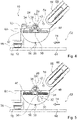
- figure 4 shows the metering element 24, 28 in its removal position.
- the dosing element 24 , 28 is placed in such a way that it can be pivoted through the receiving area 22 of the collection container 20 by rotating it through 180 degrees about the axis of rotation 36 .
- the dosing element 24, 28 is not filled.
- the dosing element 24, 28 is in the dosing position aligned with an opening of its dosing area 30 in the direction of the receiving volume 22 of the collection container 20 .
- the metering element 24, 28 is pivoted by rotating the bearing shaft 28 through 180 degrees through the receiving volume 22 of the collection container 20.
- the rotation of the metering element 24, 28 through 180 degrees is driven by the operation of the first drive unit 44.
- the dosing element 24, 28 is moved by the rotation through 180 degrees from its removal position with its dosing volume first through the receiving volume 22 of the collection container 20 and thus through the filling material 14 collected therein.
- the dosing element 24 , 28 takes up a corresponding volume of filling material 14 in its dosing area 30 .
- figure 5 shows an example of a position of the dosing element 24, 28 during pivoting about the axis of rotation 36.
- the dosing element 24, 28 is arranged in its filling position.
- the dosing area 30 of the dosing element 24 , 28 is filled with filling material 14 .
- the filling material 14 preferably protrudes beyond the dosing volume 32 of the dosing area 30 .
- the dosing element 24 is overfilled.
- the dosing element 24 , 28 is directed away from the collection container 20 with the opening of its dosing area 30 .
- the dosing element 24, 28 is linearly displaced by means of the linear bearing 46 of the storage module 26 from the removal position to a transfer position.
- the dosing element 24 , 28 is moved along the stripping element 54 .
- the scraping element 54 compresses the filling material 14 arranged in the metering region 30 of the metering element 24 , 28 and scrapes off the filling material 14 protruding beyond the metering volume 32 .
- the stripped-off filling material 14 falls back into the collection container 20.
- the dosing element 24, 26 is moved along the stripping element 54.
- the dosing element 24, 28 is stripped and in its transfer position ( figure 7 ), the dosing element 24, 28 is pivoted by rotating the bearing shaft 38 by 180 degrees via the transfer element 60 into the transfer area. By pivoting the dosing element 24, 28 by 180 degrees, the dosing element 24, 28 pivoted into its transfer position, which in figure 8 is shown. In the transfer position, the dosing element 24 , 28 is arranged with the opening of its dosing region 30 directly above the transfer element 60 . The metered filling material 14 arranged in the metering area 30 falls through the transfer element 60 into the container 12 to be filled arranged underneath.
- the dosing element 24, 28 is emptied and is brought back into its removal position for the next removal of filling material 14.
- the dosing element 24, 28 is displaced axially from the transfer position into the removal position by means of the linear bearing 46 of the storage module 26.
- the system includes a conveyor device 62.
- the conveyor device 62 is provided for transporting the containers 12 to be filled.
- the conveyor device 62 includes a conveyor belt 64.
- the conveyor belt 64 is provided for transporting the containers 12 to be filled in a transport direction 74.
- the conveyor belt 64 is designed so wide that the containers 12 to be filled at the same time can be arranged next to one another.
- the second bottling module 18 has the same design as the first bottling module 16.
- the second bottling module 18 is preferably designed as a mirror image of the first bottling module 16.
- the second filling module 18 also has a collection container 20′ and dosing elements 24′, 28′ and transfer elements 60′ that are movably mounted via a storage module 26′.
- the second filling module 18 should therefore not be described in more detail.
- the filling device 10 has a filling material feed 66 .
- the filling material feed 66 is provided for feeding the filling material 14 into the collection containers 20, 20' of the filling device 10.
- the filling material feed 66 is arranged between the filling modules 16 , 18 .
- the filling material feed 66 comprises two chutes 68, 68', via which the filling material 14 can slide into the collection containers 20, 20'.
- the system includes a conveyor belt 70 via which the filling material 14 is fed to the filling material feed 66 of the filling device 10 .
- the first filling module 16 of the filling device 10 has a lifting module 76 for each container 12 to be filled.
- the lifting modules 76 are each intended to to lift the corresponding container 12 to be filled from the conveyor belt 64 of the conveyor device 62 for filling with the filling material 14 .
- the lifting modules 76 are provided in particular to lift the containers 12 to be filled to the filling material outlet of the corresponding transfer element 60 for filling with the filling material 14 .
- the lifting modules 76 each include a weight measuring module 78 which is intended to measure the weight of the container 12 filled with the filling material 14 .
- the weight measuring module 78 has a load cell, for example, by means of which the weight of the filled container 12 can be measured. This arrangement of the weight measuring module 78 means that the load cells for measuring the weight of the containers 12 can advantageously be arranged in a dry area of the filling device 10 .
- the filling device 10 comprises a control and regulation unit 80.
- the control and regulation unit 80 is provided for controlling the filling device 10.
- the control and regulation unit 80 controls the corresponding drive units 44, 52 of the storage module 26 in order to move the dosing elements 24, 28 according to the method.
- the control and regulation unit 80 is also intended to control the lifting modules 76 .
- the control and regulation unit 80 is provided to control the weight measuring modules 78 of the lifting modules 76 and to store measured weights of the containers 12 filled with the filling material 14 .
- the filling device 10 comprises a liquid dosing module 72.
- the liquid dosing module 72 is arranged after the filling modules 16, 18 of the filling device 10, viewed in the transport direction 74 of the conveyor device 62.
- the liquid dosing module 72 comprises a spray nozzle for each container 12 to be filled, through which liquid can be dispensed into the container 12 .
- the liquid dosing module 72 is intended to fill the containers 12 to be filled with an adjusted amount of liquid depending on the weight measured by the weight measuring module 78 in order to precisely achieve a required total weight of the container 12 from the filling material 14 and the liquid.
- the control and regulation unit 80 is provided to control the liquid dosing module 72 .
- control and regulation unit 80 For each container 12 to be filled, the control and regulation unit 80 uses the filling weight measured by the corresponding weight measuring module 78 to calculate a required quantity of liquid that is needed to achieve a desired total filling weight of the filling material 14 arranged in the container 12 .
- the control and regulation unit 80 controls the liquid dosing module 72 in such a way that each container 12 is filled with the required amount of liquid.
Landscapes
- Engineering & Computer Science (AREA)
- Mechanical Engineering (AREA)
- Quality & Reliability (AREA)
- Basic Packing Technique (AREA)
- Feeding, Discharge, Calcimining, Fusing, And Gas-Generation Devices (AREA)
Description
- Aus
US 936,169 A ist bereits eine Abfüllvorrichtung, insbesondere Nahrungsmittelabfüllvorrichtung, zu einem Dosieren eines vorgegebenen Gewichts und/oder Volumens eines zu dosierenden Füllguts, bekannt, wobei die Abfüllvorrichtung einen Sammelbehälter, der dazu vorgesehen ist, dass das zu dosierende Füllgut darin gesammelt ist, ein Dosierelement, das für eine Dosierung des Füllguts zur Entnahme eines definierten Volumens des Füllguts aus dem Sammelbehälter vorgesehen ist, und ein Lagermodul umfasst, das das Dosierelement beweglich lagert. - Die Erfindung geht aus von einer Abfüllvorrichtung, insbesondere Nahrungsmittelabfüllvorrichtung, zu einem Dosieren eines vorgegebenen Gewichts und/oder Volumens eines zu dosierenden Füllguts, mit einem Sammelbehälter, der dazu vorgesehen ist, dass das zu dosierende Füllgut darin gesammelt ist, mit einem Dosierelement, das insbesondere als ein Dosierlöffel ausgebildet ist, das für eine Dosierung des Füllguts zur Entnahme eines definierten Volumens des Füllguts aus dem Sammelbehälter vorgesehen ist, und mit einem Lagermodul, das das Dosierelement beweglich lagert. Es wird vorgeschlagen, dass das Lagermodul zumindest ein Linearlager aufweist, mittels dessen das Dosierelement zwischen einer Entnahmestellung und einer Übergabestellung verstellt werden kann.
- Unter einer "Abfüllvorrichtung" soll vorzugsweise eine Vorrichtung verstanden werden, die dazu vorgesehen ist, ein Gut, vorzugsweise ein Füllgut, dosiert in zumindest ein zu befüllendes Behältnis, vorzugsweise in mehrere zu befüllende Behältnisse, abzufüllen. Vorzugsweise ist die Abfüllvorrichtung dazu vorgesehen, mehrere Behältnisse zeitgleich mit einem definierten Gewicht und/oder Volumen eines Füllguts zu befüllen. Unter einer "Nahrungsmittelabfüllvorrichtung" soll vorzugsweise eine Abfüllvorrichtung verstanden werden, die dazu vorgesehen ist, ein als Lebensmittel ausgebildetes Füllgut dosiert in zu befüllende Behältnisse abzufüllen. Unter einem "zu dosierenden Füllgut" soll vorzugsweise ein Schüttgut verstanden werden, also vorzugsweise ein pulvriges, körniges und/oder stückiges Gemenge, das in einer schüttfähigen Form vorliegt. Vorzugsweise kann das zu dosierende Füllgut einen Feuchtigkeitsanteil aufweisen. Unter einem "Sammelbehälter" soll vorzugsweise ein Behältnis verstanden werden, in dem das zu dosierende Füllgut aufgefangen, vorzugsweise gesammelt, werden kann. In dem Sammelbehälter ist das Füllgut vorzugsweise zu einer dosierten Entnahme angeordnet, also gesammelt. Der Sammelbehälter weist eine konkave Innenkontur auf, die ein Aufnahmevolumen des Sammelbehälters ausbildet, in dem das Füllgut zur dosierten Entnahme angeordnet ist. Unter einem "Dosierelement" soll vorzugsweise ein Element verstanden werden, dass ein Dosiervolumen aufspannt, das zu einer Dosierung eines Füllguts dazu vorgesehen ist, mit dem Füllgut gefüllt zu werden. Das Dosierelement weist vorzugsweise einen konvexen Dosierbereich auf, der das Dosiervolumen begrenzt. Der konvexe Dosierbereich ist als eine Ausnehmung ausgebildet. Vorzugsweise ist das Dosierelement als ein Dosierlöffel ausgebildet. Unter einem "Dosierlöffel" soll vorzugsweise ein Element verstanden werden, das einen Verbindungssteg und eine an einem Ende des Verbindungsstegs angeordnete Löffelschale aufweist, die vorzugsweise den konvexen Dosierbereich ausbildet. Unter einem "Lagermodul" soll vorzugsweise ein Modul verstanden werden, das zur beweglichen Lagerung zumindest eines Elements, vorzugsweise des Dosierelements, vorgesehen ist. Das Lagermodul ist vorzugsweise dazu vorgesehen, ein zu lagerndes Element, wie vorzugsweise das Dosierelement, rotatorisch und/oder linear verschiebbar zu lagern. Dadurch kann eine besonders einfache Dosierung eines zu dosierenden Füllguts mittels der Abfüllvorrichtung erreicht werden.
- Des Weiteren wird vorgeschlagen, dass das Dosierelement zur Entnahme des definierten Volumens des Füllguts aus dem Sammelbehälter dazu vorgesehen ist, mittels des Lagermoduls durch ein Aufnahmevolumen des Sammelbehälters bewegt zu werden. Unter einem "Aufnahmevolumen" soll vorzugsweise ein Volumen verstanden werden, das von dem Sammelbehälter, insbesondere einer konkaven Innenkontur des Aufnahmebehälters, aufgespannt wird. Das Aufnahmevolumen definiert vorzugsweise einen Raum, in dem das Füllgut gesammelt werden kann. Unter "durch das Aufnahmevolumen bewegt zu werden" soll vorzugsweise verstanden werden, dass zumindest ein konvexer Dosierbereich des Dosierelements so durch den Sammelbehälter geführt wird, dass das in dem Sammelbehälter gesammelte Füllgut von dem Dosierbereich aufgenommen werden kann. Vorzugsweise wird das Dosierelement in eine Linear- und/oder Rotationsbewegung durch das Aufnahmevolumen des Sammelbehälters geführt. Vorzugsweise wird der konvexe Dosierbereich des Dosierelements in einer Linearund/oder Rotationsbewegung durch das Aufnahmevolumen des Sammelbehälters geführt. Besonders bevorzugt wird das Dosierelement in einer Schwenkbewegung durch das Aufnahmevolumen des Sammelbehälters bewegt. Grundsätzlich ist es auch denkbar, dass das Dosierelement in einer Linearbewegung oder in einer kombinierten Linear- und Rotationsbewegung durch das Aufnahmevolumen des Sammelbehälters geführt wird. Dadurch kann eine Entnahme des Füllguts aus dem Sammelbehälter besonders einfach erfolgen und die Dosiervorrichtung besonders einfach ausgebildet werden.
- Zudem wird vorgeschlagen, dass das Lagermodul eine Rotationsachse ausbildet und dazu vorgesehen ist, das Dosierelement zur Entnahme des definierten Volumens des Füllguts aus dem Sammelbehälter um die Rotationsachse zu rotieren. Dadurch kann das Dosierelement mittels der Lagervorrichtung zur Entnahme des Füllguts besonders vorteilhaft gelagert werden.
- Ferner wird vorgeschlagen, dass das Lagermodul dazu vorgesehen ist, das Dosierelement zur Übergabe des entnommenen Füllguts an ein zu befüllendes Behältnis um die Rotationsachse zu rotieren. Dadurch kann eine Übergabe des Füllguts aus dem Dosierelement besonders einfach durchgeführt werden.
- Unter einem "Linearlager" soll vorzugsweise ein Lager verstanden werden, das zumindest zwei entlang einer Lagerachse zueinander linear verschiebbare Lagerelemente umfasst. Ein erstes Lagerelement des Linearlagers ist vorzugsweise als eine Linearlagerschiene ausgebildet. Unter einer "Linearlagerschiene" soll insbesondere ein Linearführungselement verstanden werden, das dazu vorgesehen ist, eine Lagerbahn, vorzugsweise eine gerade Lagerachse, auszubilden, entlang der ein weiteres Element linear auf der Linearlagerschiene verschiebbar ist. Eine Linearlagerschiene ist dazu vorgesehen, dass ein Führungselement form- und/oder kraftschlüssig auf ihr angebunden ist, wobei das Führungselement zumindest entlang einer Bahn, insbesondere entlang der Lagerachse, einen Freiheitsgrad relativ zu der Linearlagerschiene aufweist. Ein zweites Lagerelement des Linearlagers kann vorzugsweise als ein Führungselement ausgebildet sein. Das zweite Lagerelement ist korrespondierend zu dem ersten Lagerelement ausgebildet und dazu vorgesehen, beweglich zu dem ersten Lagerelement gelagert zu sein. Das zweite Lagerelement ist vorzugsweise entlang der Lagerbahn beweglich zu dem ersten Lagerelement gelagert. Das zweite Lagerelement ist vorzugsweise als ein Lagerschlitten ausgebildet, das beweglich zu dem ersten, als Linearlagerschiene ausgebildeten Lagerelement, gelagert ist. Das zweite Lagerelement weist vorzugsweise einen Grundkörper und wenigstens ein mit dem Grundkörper verbundenes Führungselement auf, das dazu vorgesehen ist, mit dem ersten Lagerelement zur beweglichen Lagerung des zweiten Lagerelements verbunden zu werden. Unter einer "Entnahmestellung" soll vorzugsweise eine axiale Positionierung des Dosierelements auf dem Linearlager verstanden werden, in der das Dosierelement so axial positioniert ist, dass es durch den Sammelbehälter geführt werden kann, um das Füllgut aus dem Sammelbehälter zu entnehmen. Unter einer "Übergabestellung" soll vorzugsweise eine axiale Positionierung des Dosierelements auf dem Linearlager verstanden werden, in der das Dosierelement so axial positioniert ist, dass es das aufgenommene Füllgut durch eine definierte Bewegung, vorzugsweise eine Rotation, zu einem zu befüllenden Behältnis bewegen kann. Dadurch kann das Dosierelement besonders einfach zwischen der Entnahmestellung und der Übergabestellung verstellt werden.
- Zudem wird vorgeschlagen, dass die Abfüllvorrichtung ein Abstreifelement aufweist, das vor einer Übergabe des Füllguts dazu vorgesehen ist, das in dem Dosierelement angeordnete Füllgut auf das vorgegebene Volumen zu reduzieren. Unter einem "Abstreifelement" soll vorzugsweise ein Element verstanden werden, das dazu vorgesehen ist, überschüssiges, also über eine maximale Füllmenge hinausgehendes Füllgut abzustreifen, also aus dem Dosierelement zu entfernen und vorzugsweise zurück in den Sammelbehälter zu bringen. Durch das Abstreifelement wird das von dem Dosierelement aufgenommene Füllgut durch Vorbeifahren an dem Abstreifelement immer auf ein gleiches definiertes Volumen reduziert werden. Dadurch kann besonders vorteilhaft eine genaue und gleichbleibende Entnahme eines definierten Volumens an Füllgut mittels des Dosierelements erreicht werden.
- Ferner wird vorgeschlagen, dass die Lagervorrichtung dazu vorgesehen ist, das Dosierelement bei einer Verstellung von der Entnahmestellung in die Übergabestellung an dem Abstreifelement vorbeizuführen, um das in dem Dosierelement angeordnete Füllgut abzustreifen und/oder zu verdichten. Unter "an dem Abstreifelement vorbeizuführen" soll vorzugsweise verstanden werden, dass das Dosierelement zumindest mit seinem Dosierbereich an dem Abstreifelement entlanggeführt wird, wobei das Abstreifelement vorzugsweise an einem oberen Rand des Dosierbereichs anliegt. Vorzugsweise wird das Dosierelement so an dem Abstreifelement vorbeigeführt, dass das Abstreifelement genau an einem oberen Ende des Dosiervolumens angeordnet ist und so das Dosiervolumen begrenzt. Unter "abzustreifen und/oder zu verdichten" soll vorzugsweise verstanden werden, dass das Abstreifelement Füllgut, welches über das Dosiervolumen, also einen oberen Rand des Dosierbereichs hinausragt, zumindest zu einem Teil abstreift, also von dem Dosierelement entfernt und/oder einen Teil auch in das Dosiervolumen des Dosierbereichs hineindrückt, um so das in dem Dosiervolumen des Dosierbereichs angeordnete Füllgut zu verdichten. Dadurch kann das in dem Dosierelement angeordnete Füllgut besonders einfach und genau auf ein gewünschtes Volumen und/oder Gewicht eingestellt werden.
- Des Weiteren wird vorgeschlagen, dass die Abfüllvorrichtung zumindest ein Übergabeelement aufweist, über das das zu dosierende Füllgut in einer Übergabeposition des Dosierelements von dem Dosierelement direkt zu einem zu befüllenden Behältnis geleitet werden kann. Unter einem "Übergabeelement" soll vorzugsweise ein Element verstanden werden, durch oder über das ein Füllgut von einem ersten Ende zu einem zweiten Ende geleitet werden kann. Das Füllgut wird vorzugsweise durch die Schwerkraft durch das Übergabeelement bewegt. Das Übergabeelement ist vorzugsweise als ein Rohrelement ausgebildet, durch das das Füllgut fallen kann. Das Übergabeelement ist vorzugsweise als ein Fallrohr ausgebildet. Das als Übergaberohr ausgebildete Übergabeelement ist vorzugsweise senkrecht ausgerichtet, sodass ein Füllguteingang und ein Füllgutausgang übereinander angeordnet sind. Grundsätzlich ist es ebenso denkbar, dass das Übergabeelement als eine geneigte Rinne oder ein geneigtes Rutschblech ausgebildet ist, über das ein Füllgut von einem ersten Ende zu einem zweiten Ende gleiten kann. Unter einem "zu befüllenden Behältnis" soll vorzugsweise ein Behältnis verstanden werden, das zur sicheren Aufbewahrung und Frischhaltung des Füllguts vorgesehen ist. Ein zu füllendes Behältnis kann beispielsweise als ein Plastikbecher, eine Blechdose, ein Pappbecher, oder als ein anderes, dem Fachmann als sinnvoll erscheinendes, zur Aufbewahrung eines Füllguts, insbesondere eines Lebensmittels, vorgesehenes Behältnis sein.
- Dadurch kann das dosierte Füllgut besonders betriebssicher vollständig von dem Dosierelement zu dem zu befüllenden Behältnis geleitet werden. Besonders vorteilhaft kann das Füllgut bei einer Ausgestaltung des Übergabeelements als ein senkrecht ausgerichtetes Fallrohr zu dem zu befüllenden Behältnis geführt werden.
- Es wird weiter vorgeschlagen, dass der Sammelbehälter als eine Wanne ausgebildet ist, deren Innenkontur zumindest in einem Teilbereich eine gleichmäßige Krümmung aufweist. Darunter, dass die Innenkontur "zumindest in einem Teilbereich eine gleichmäßige Krümmung aufweist" soll vorzugsweise verstanden werden, dass zumindest 50%, vorzugsweise 75% und in einer besonders vorteilhaften Ausgestaltung über 90% der Innenkontur eine gleichmäßige Krümmung aufweist. Besonders bevorzugt bildet die Innenkontur des als Wanne ausgebildeten Sammelbehälters eine Halbkreisform aus. Grundsätzlich ist es auch denkbar, dass lediglich ein mittlerer Teilbereich der Innenkontur des als Wanne ausgebildeten Sammelbehälters eine gleichmäßige Krümmung aufweist und äußere Bereiche eine kleinere Krümmung oder eine Gerade ausbilden. Dadurch kann der Sammelbehälter besonders vorteilhaft zur Entnahme des Füllguts mittels des Dosierelements ausgebildet werden.
- Ferner wird vorgeschlagen, dass die Abfüllvorrichtung eine Abflussvorrichtung aufweist, die dazu vorgesehen ist, eine Flüssigkeit aus dem Sammelbehälter abzutransportieren, wobei eine Austrittsöffnung unterhalb einer minimalen Schöpfhöhe des Dosierelements angeordnet ist. Unter einer "Abflussvorrichtung" soll vorzugsweise eine Vorrichtung verstanden werden, durch die eine Flüssigkeit durch die Schwerkraft aus dem Sammelbehälter abfließen kann oder aktiv aus dem Sammelbehälter abgesaugt werden kann. Unter einer "minimalen Schöpfhöhe" soll vorzugsweise eine minimale Höhe in dem Sammelbehälter verstanden werden, bis auf die sich das Dosierelement mit seinem Dosierbereich maximal erstrecken kann. Unter "unterhalb der minimalen Schöpfhöhe" soll vorzugsweise verstanden werden, näher zu einem Boden, also einer Ebene, auf dem die Abfüllvorrichtung aufgestellt ist, angeordnet. Dadurch kann Flüssigkeit vorteilhaft aus dem Sammelbehälter entfernt werden, wodurch eine Verklebung des Dosierelements und/oder anderer Teile der Abfüllvorrichtung durch Flüssigkeit, die beispielsweise aus dem Füllgut austreten kann, vermieden werden kann. Dadurch kann insbesondere eine Sauberkeit, eine Genauigkeit der Abfüllvorrichtung verbessert werden.
- Zudem wird vorgeschlagen, dass die Abfüllvorrichtung zumindest ein weiteres Dosierelement aufweist, das parallel zu dem einen Dosierelement über das Lagermodul beweglich gelagert ist und für eine Dosierung des Füllguts zur Entnahme eines definierten Volumens des Füllguts aus dem Sammelbehälter vorgesehen ist. Unter einem "weiteren Dosierelement" soll vorzugsweise ein gleich ausgebildetes Dosierelement verstanden werden, das über das gleiche Lagermodul angebunden ist und vorzugsweise genau gleich ausgebildet ist wie das erste Dosierelement. Grundsätzlich wäre es auch denkbar, dass ein weiteres Dosierelement ein größeres Dosiervolumen ausbildet, wodurch mittels der Abfüllvorrichtung nebeneinander unterschiedlich große Behältnisse befüllbar wären. Dadurch kann die Abfüllvorrichtung besonders vorteilhaft zur Abfüllung in mehrere Behältnisse ausgebildet werden.
- Ferner wird vorgeschlagen, dass die Abfüllvorrichtung zumindest ein Flüssigkeitsdosierungsmodul aufweist, das dazu vorgesehen ist, nach einer Befüllung eines zu befüllenden Behältnisses mit Füllgut mittels des Dosierelements das Behältnis mit einer Flüssigkeit zu befüllen, bis ein gewünschtes Gesamtfüllvolumen und/oder Gesamtfüllgewicht erreicht ist. Unter einem "Flüssigkeitsdosierungsmodul" soll vorzugsweise ein Modul verstanden werden, das eine Flüssigkeit zu dem dosierten Füllgut in das zu befüllende Behältnis geben kann. Vorzugsweise wird eine Flüssigkeit in das Behältnis eingespritzt. Vorzugsweise ist das Flüssigkeitsdosiermodul beabstandet, also räumlich getrennt von den Dosierelementen und dem Sammelbehälter angeordnet. So kann die Abfüllvorrichtung vorteilhaft in einen Trockenbereich, nämlich die Dosierung mittels der Dosierelemente, und einen Nassbereich, nämlich die Befüllung von Flüssigkeit mittels des Flüssigkeitsdosiermoduls, aufgeteilt werden. Dadurch kann ein Gesamtgewicht des in dem Behältnis angeordneten Füllguts und der Flüssigkeit besonders gut eingestellt werden. Ferner kann durch eine Trennung der Dosierung des trockenen Füllguts und der Abfüllung der Flüssigkeit eine vorteilhafte Trennung eines Trockenbereichs und eines Flüssigkeitsbereichs der Abfüllvorrichtung erreicht werden, wodurch flüssigkeitsempfindliche Bauteile, wie beispielsweise Wägezellen, vorteilhaft außerhalb des Flüssigkeitsbereichs angeordnet werden können.
- Außerdem wird ein System mit zumindest einer Abfüllvorrichtung zum Befüllen von zu befüllenden Behältnissen eines vorgegebenen Gewichts und/oder Volumens eines zu dosierenden Füllguts vorgeschlagen. Vorzugsweise weist das System eine Steuer- und/oder Regeleinheit auf, die dazu vorgesehen ist, die Abfüllvorrichtung zu steuern. Unter einer "Steuer- und/oder Regeleinheit" soll insbesondere eine Einheit mit zumindest einer Steuerelektronik verstanden werden. Unter einer "Steuerelektronik" soll insbesondere eine Einheit mit einer Prozessoreinheit und mit einer Speichereinheit sowie mit einem in der Speichereinheit gespeicherten Betriebsprogramm verstanden werden. Unter "eingerichtet" soll insbesondere speziell programmiert und/oder speziell ausgestattet verstanden werden. Darunter, dass ein Objekt, insbesondere die Steuer- und/oder Regeleinheit, zu einer bestimmten Funktion, insbesondere einer Anpassung der Übergabekenngröße, eingerichtet ist, soll insbesondere verstanden werden, dass das Objekt diese bestimmte Funktion in zumindest einem Anwendungs- und/oder Betriebszustand erfüllt und/oder ausführt. Durch die erfindungsgemäße Ausgestaltung des Systems kann eine vorteilhafte, dosierte Abfüllung eines Füllguts in ein oder mehrere Behältnisse erreicht werden.
- Zusätzlich wird ein Verfahren zu einem Dosieren eines Füllguts mittels einer Abfüllvorrichtung vorgeschlagen.
- Die erfindungsgemäße Vorrichtung, das erfindungsgemäße System und/oder das erfindungsgemäße Verfahren sollen/soll hierbei nicht auf die oben beschriebene Anwendung und Ausführungsform beschränkt sein. Insbesondere können/kann die erfindungsgemäße Vorrichtung, das erfindungsgemäße System und/oder das erfindungsgemäße Verfahren zu einer Erfüllung einer hierin beschriebenen Funktionsweise eine von einer hierin genannten Anzahl von einzelnen Elementen, Bauteilen und Einheiten sowie Verfahrensschritten abweichende Anzahl aufweisen. Zudem sollen bei den in dieser Offenbarung angegebenen Wertebereichen auch innerhalb der genannten Grenzen liegende Werte als offenbart und als beliebig einsetzbar gelten.
- Weitere Vorteile ergeben sich aus der folgenden Zeichnungsbeschreibung. In den Zeichnungen ist ein Ausführungsbeispiel der Erfindung dargestellt. Die Zeichnungen, die Beschreibung und die Ansprüche enthalten zahlreiche Merkmale in Kombination. Der Fachmann wird die Merkmale zweckmäßigerweise auch einzeln betrachten und zu sinnvollen weiteren Kombinationen zusammenfassen.
- Es zeigen:
- Fig. 1
- eine schematische Ansicht eines Systems mit einer Abfüllvorrichtung,
- Fig. 2
- eine weitere Ansicht der Abfüllvorrichtung mit einer Fördervorrichtung,
- Fig. 3
- eine Seitenansicht durch die Abfüllvorrichtung mit der Fördervorrichtung und einem Flüssigkeitsdosierungsmodul,
- Fig. 4
- eine Detailseitenansicht eines Abfüllmoduls der Abfüllvorrichtung mit einem Dosierelement in einer Entnahmeposition,
- Fig. 5
- eine weitere Detailseitenansicht mit dem Dosierelement während einer Entnahme von Füllgut aus einem Sammelbehälter,
- Fig. 6
- eine weitere Detailseitenansicht mit dem Dosierelement nach der Entnahme des Stückguts,
- Fig. 7
- eine weitere Detailseitenansicht mit dem Dosierelement nach einem linearen Verfahren in eine Übergabestellung und
- Fig. 8
- eine weitere Detailseitenansicht mit dem Dosierelement nach einer Rotation in eine Übergabeposition.
- Die
Figuren 1 bis 8 zeigen ein erfindungsgemäßes System mit einer Abfüllvorrichtung 10. Das System mit der Abfüllvorrichtung 10 ist zum Befüllen von zu befüllenden Behältnissen 12, 12' mit einem vorgegebenen Gewicht und/oder Volumen eines zu dosierenden Füllguts 14 vorgesehen. Die Abfüllvorrichtung 10 ist als eine Nahrungsmittelabfüllvorrichtung ausgebildet. Die Abfüllvorrichtung 10 ist zur dosierten Abfüllung eines als Nahrungsmittel ausgebildeten Füllguts 14 vorgesehen. Die Abfüllvorrichtung 10 ist zu einem Dosieren eines vorgegebenen Gewichts und/oder Volumens des zu dosierenden Füllguts 14 vorgesehen. Das Füllgut 14 sind beispielsweise Fruchtstücke. Vorzugsweise ist das Füllgut 14 von Fruchtstücken gebildet, die einen Flüssigkeitsanteil aufweisen können. Grundsätzlich ist es auch denkbar, dass das Füllgut 14 als ein Pulver oder ein anderes stückiges Schüttgut ausgebildet ist. Das System umfasst eine Füllgutzufuhr. Die Füllgutzufuhr ist hier beispielhaft als ein Förderband ausgebildet. Grundsätzlich ist es auch denkbar, dass die Füllgutzufuhr auf ein andere, dem Fachmann als sinnvoll erscheinende Weise ausgebildet ist. - Die Abfüllvorrichtung 10 umfasst zwei Abfüllmodule 16, 18. Die beiden Abfüllmodule 16, 18 sind im Wesentlichen gleich ausgebildet, weswegen im Folgenden lediglich das erste Abfüllmodul 16 näher beschrieben werden soll. Zur Erläuterung des zweiten Abfüllmoduls 18 kann die Beschreibung des ersten Abfüllmoduls 16 herangezogen werden. Die beiden Abfüllmodule 16, 18 sind in Reihe hintereinandergeschaltet.
- Das Abfüllmodul 16 der Abfüllvorrichtung 10 umfasst einen Sammelbehälter 20. Der Sammelbehälter 20 ist als eine Sammelwanne ausgebildet. Der Sammelbehälter 20 ist als eine längliche Wanne ausgebildet. Der Sammelbehälter 20 weist eine Innenkontur auf, die eine gleichmäßige Krümmung aufweist. Der Sammelbehälter 20 weist eine halbkreisförmige Innenkontur auf. Der Sammelbehälter 20 bildet ein Aufnahmevolumen 22 aus. Die Innenkontur des Sammelbehälters 20 begrenzt das Aufnahmevolumen 22. Der Sammelbehälter 20 ist dazu vorgesehen, dass das zu dosierende Füllgut 14 darin gesammelt wird. Der Sammelbehälter 20 ist über eine nicht näher dargestellte Aufständereinheit aufgeständert.
- Die Aufständereinheit könnte beispielsweise von einem Gestell, das auf Füßen steht, ausgebildet sein.
- Das Abfüllmodul 16 der Abfüllvorrichtung 10 weist ein Dosierelement 24 auf. Das Dosierelement 24 ist für eine Dosierung des Füllguts 14 zur Entnahme eines definierten Volumens des Füllguts 14 aus dem Sammelbehälter 20 vorgesehen. Die Abfüllvorrichtung 10 umfasst ein Lagermodul 26, das zur Lagerung des Dosierelements 24 vorgesehen ist. Mittels des Lagermoduls 26 ist das Dosierelement 24 beweglich gelagert. Das Dosierelement 24 ist über das Lagermodul 26 relativ zu dem Sammelbehälter 20 beweglich gelagert. Das Abfüllmodul 16 der Abfüllvorrichtung 10 weist weitere Dosierelemente 28 auf. Die Dosierelemente 28 sind parallel zu dem Dosierelement 24 angeordnet. Die weiteren Dosierelemente 28 sind ebenfalls über das Lagermodul 26 beweglich gelagert. Die weiteren Dosierelemente 28 sind für eine Dosierung des Füllguts 14 zur Entnahme eines definierten Volumens des Füllguts 14 aus dem Sammelbehälter 20 vorgesehen. Mittels der weiteren Dosierelemente 28 und dem Dosierelement 24 kann zeitgleich jeweils eine Entnahme eines definierten Volumens des Füllguts 14 aus dem Sammelbehälter 20 erfolgen. In der gezeigten Ausgestaltung weist das erste Abfüllmodul 16 der Abfüllvorrichtung 10 zehn Dosierelemente 24, 28 auf, die mittels des Lagermoduls 26 beweglich gelagert und zur Entnahme eines definierten Volumens des Füllguts 14 aus dem Sammelbehälter 20 vorgesehen sind. Grundsätzlich wäre es auch denkbar, dass das erste Abfüllmodul 16 eine andere Anzahl an Dosierelementen 24, 28 aufweist, beispielsweise vier oder zwanzig. Die Dosierelemente 24, 28 sind gleich ausgebildet. Deswegen soll im Folgenden lediglich das eine Dosierelement 24 näher beschrieben werden. Zur Erläuterung aller anderen Dosierelemente 28 kann die folgende Beschreibung des einen Dosierelements 24 herangezogen werden.
- Das Dosierelement 24 ist als ein Dosierlöffel ausgebildet. Das als Dosierlöffel ausgebildete Dosierelement 24 weist an einem ersten Ende einen konvexen Dosierbereich 30 auf. Der konvexe Dosierbereich 30 spannt ein Dosiervolumen 32 auf. Der konvexe Dosierbereich 30 weist eine zylinderförmige Innenkontur auf. Grundsätzlich ist es auch denkbar, dass der Dosierbereich 30 als eine halbkugelförmige Innenkontur ausgebildet ist, oder die Innenkontur eine andere, dem Fachmann als sinnvoll erscheinende Form aufweist. Das Dosiervolumen 32, das von dem konvexen Dosierbereich 30 des Dosierelements 24 aufgespannt wird, entspricht dem zu dosierenden Volumen des Füllguts 14. Das Dosierelement 24 weist einen Verbindungssteg 34 auf. Der Dosierbereich 30 ist an einem ersten Ende des Verbindungsstegs 34 angebunden. Der Dosierbereich 30 kann einstückig mit dem Verbindungssteg 34 ausgebildet sein. Grundsätzlich ist es auch denkbar, dass der Dosierbereich 30 in einem separat von dem Verbindungssteg 34 ausgebildeten Element eingebracht ist, das in einem montierten Zustand mit dem Verbindungssteg 34 verbunden ist. Dadurch könnten besonders einfach unterschiedlich große Dosierbereiche 30 mit dem Verbindungsteg 34 verbunden werden und einfach Dosierelemente 24 mit unterschiedlich großen Volumina zur Dosierung des Füllguts 14 bereitgestellt werden. An einem zweiten Ende ist der Verbindungssteg 34 des Dosierelements 24 mit dem Lagermodul 26 verbunden. Das Dosierelement 24 ist zur Entnahme eines definierten Volumens des Füllguts 14 aus dem Sammelbehälter 20 vorgesehen. Das Dosierelement 24 wird zur dosierten Entnahme des Füllguts 14 aus dem Sammelbehälter 20 zumindest mit seinem Dosiervolumen 32 durch das Aufnahmevolumen 22 des Sammelbehälters 20 bewegt.
- Das Lagermodul 26 bildet eine Rotationsachse 36 aus. Das Lagermodul 26 weist eine Lagerwelle 38 auf, die die Rotationsachse 36 ausbildet. Die Lagerwelle 38 ist zur Anbindung des Dosierelements 24, 28 vorgesehen. Die Lagerwelle 38 verläuft in einer Querrichtung zu dem Sammelbehälter 20. Die Lagerwelle 38 verläuft in einem montierten Zustand parallel zu einer Querachse des Lagerbehälters. Die Lagerwelle 38 ist um ihre Mittelachse, die der Rotationsachse 36 entspricht, drehbar gelagert. Das Lagermodul 26 weist zwei Lagerböcke 40, 42 auf, an denen die Lagerwelle 38 drehbar gelagert ist. Die Lagerböcke 40, 42 sind jeweils auf gegenüberliegenden Längsseiten des Sammelbehälters 20 angeordnet. Die Lagerböcke 40, 42 weisen jeweils eine Lageraufnahme auf, in der die Lagerwelle 38 drehbar gelagert ist. Die beiden Lagerböcke 40, 42 sind mit ihren Lageraufnahmen koaxial zueinander angeordnet. Das Lagermodul 26 umfasst eine erste Antriebseinheit 44. Die erste Antriebseinheit 44 ist als ein Elektromotor ausgebildet. Grundsätzlich wäre es auch denkbar, dass die erste Antriebseinheit 44 als eine andere Antriebseinheit ausgebildet ist, beispielsweise als ein pneumatischer oder hydraulischer Motor. Die Antriebseinheit 44 ist zum Antrieb der Lagerwelle 38 vorgesehen. Dadurch ist die Antriebseinheit 44 zur Bewegung des Dosierelements 24 vorgesehen. Die erste Antriebseinheit 44 ist an dem einen Lagerbock 40 angebunden.
- Das Lagermodul 26 weist zwei Linearlager 46 auf. Die Linearlager 46 sind dazu vorgesehen, jeweils einen Lagerbock 40, 42 relativ zu dem Sammelbehälter 20 zu lagern. Die Linearlager 46 bilden jeweils eine Lagerachse aus, entlang der die Lagerböcke 40, 42 linear verschiebbar sind. Die Lagerachsen der beiden Linearlager 46 verlaufen parallel zueinander. Die Linearlager 46 weisen jeweils eine Lagerschiene 48 auf. Die Lagerschiene 48 ist an einer Außenseite einer Seitenwand des Sammelbehälters 20 angebracht. Grundsätzlich ist es auch denkbar, dass das Lagermodul 26 ein eigenes Gestell aufweist, an dem die Lagerschienen 48 der Linearlager 46 jeweils neben der Seitenwand des Sammelbehälters 20 positionsfest angeordnet sind. Die Linearlager 46 weisen jeweils ein Führungselement 50 auf. Die Führungselemente 50 sind jeweils formschlüssig mit der entsprechenden Lagerschiene 48 des Linearlagers 46 verbunden. Die Führungselemente 50 sind jeweils axial verschiebbar mit der Lagerschiene 48 gekoppelt. Die Führungselemente 50 sind entlang der Lagerachse zu den Lagerschienen 48 axial verschiebbar. Die Führungselemente 50 sind jeweils mit einem der Lagerböcke 40, 42 fest verbunden. Grundsätzlich ist es auch denkbar, dass die Führungselemente 50 einstückig mit dem jeweiligen Lagerbock 40, 42 ausgebildet sind. Das Lagermodul 26 umfasst eine zweite Antriebseinheit 52, die zur axialen Verschiebung des Führungselements 50 in der Lagerschiene 48 vorgesehen ist. Die zweite Antriebseinheit 52 ist als ein Elektromotor ausgebildet. Das Lagermodul 26 umfasst eine nicht näher dargestellte Getriebeeinheit, die dazu vorgesehen ist, eine Rotationsbewegung der zweiten Antriebseinheit 52 in eine Axialbewegung des Führungselements 50 zu der Lagerschiene 48 umzusetzen. Die Getriebeeinheit könnte beispielsweise ein mit dem Führungselement 50 verbundenes, mittels der Antriebseinheit 52 rotatorisch eintreibbares Zahnrad umfassen, das in eine mit der Lagerschiene 48 gekoppelte Zahnstange eingreift.
- Das Dosierelement 24 ist mit der Lagerwelle 38 verbunden. Das Dosierelement 24 ist mit einem zweiten, dem Dosierbereich 30 gegenüberliegenden Ende mit der Lagerwelle 38 fest verbunden. Vorzugsweise ist das Dosierelement 24 mittels einer Schraubenverbindung mit der Lagerwelle 38 verbunden. Grundsätzlich ist es auch denkbar, dass das Dosierelement 24 form- und/oder stoffschlüssig, beispielsweise durch eine Schweiß- oder Klebeverbindung, fest mit der Lagerwelle 38 verbunden ist. Mittels des Lagermoduls 26 ist das Dosierelement 24 entlang der Lagerachse der Linearlager 46 axial verschiebbar und um die Rotationsachse 36 der Lagerwelle 38 rotierbar relativ zu dem Sammelbehälter 20 gelagert. Alle Dosierelemente 24, 28 sind mit der Lagerwelle 38 verbunden. Mittels des Lagermoduls 26 sind alle Dosierelemente 24, 28 des Abfüllmoduls 16 der Abfüllvorrichtung entlang der Lagerachse der Linearlager 46 axial verschiebbar und um die Rotationsachse 36 der Lagerwelle 38 rotierbar relativ zu dem Sammelbehälter 20 gelagert. Alle Dosierelemente 24, 28 des Abfüllmoduls 16 der Abfüllvorrichtung 10 sind mittels des Lagermoduls 38 gleichzeitig und in einer gleichen Weise axial verschiebbar und rotierbar.
- Das Abfüllmodul 16 der Abfüllvorrichtung 10 weist ein Abstreifelement 54 auf. Das Abstreifelement 54 ist dazu vorgesehen, vor einer Übergabe des Füllguts 14 das in dem Dosierelement 24 angeordnete Füllgut 14 auf das vorgegebene Volumen zu reduzieren. Das Abstreifelement 54 ist dazu vorgesehen, über das Dosiervolumen 32 des Dosierelements 24 hinausragendes Füllgut 14 abzustreifen. Ferner ist das Abstreifelement 54 dazu vorgesehen, das in dem Dosiervolumen 32 des Dosierelements 24 angeordnete Füllgut 14 zu verdichten. Durch das Abstreifen von überschüssigem Füllgut 14, das aus dem Dosiervolumen 32 hinausragt, kann mittels des Abstreifelements 54 das von dem Dosierelement 24 aufgenommene Füllgut 14 auf ein immer gleiches Volumen reduziert werden. Durch das Verdichten des in dem Dosierbereich 30 des Dosierelements 24 angeordneten Füllguts 14 kann eine gleichmäßige Füllung des Dosierbereichs 30 mit dem Füllgut 14 erreicht werden. Zum Abstreifen und Verdichten wird das Dosierelement 24 an dem Abstreifelement 54 entlanggeführt. Grundsätzlich ist auch eine Bewegung des Abstreifelements 54 denkbar, sodass dieses an dem Dosierelement 24 entlanggefahren wird. Bei dem Entlangfahren des Dosierelements 24 an dem Abstreifelement 54 wird vorzugsweise zeitgleich das in dem Dosierbereich 30 angeordnete Füllgut 14 in dem Dosiervolumen 32 verdichtet und Füllgut 14, das nicht in das Dosiervolumen 32 gedrückt werden kann und deshalb über das Dosiervolumen 32 hinausragt, abgestreift. Das abgestreifte Füllgut 14 fällt zurück in den Sammelbehälter 20. Das Abstreifelement 54 liegt, während das Dosierelement 24 vorbeigeführt wird, vorzugsweise auf einem oberen Rand des Dosierbereichs 30. Grundsätzlich ist es auch denkbar, dass ein kleiner Spalt zwischen dem Dosierelement 24 und dem Abstreifelement 54 bestehen bleibt. Das Abstreifelement 54 ist als ein Stab ausgebildet. Das als Stab ausgebildete Abstreifelement 54 erstreckt sich über eine gesamte Breite des Sammelbehälters 20. Das als Stab ausgebildete Abstreifelement 54 erstreckt sich über alle Dosierelemente 24, 28 und ist zum Abstreifen aller Dosierelemente 24, 28 vorgesehen. Das Abstreifelement 54 weist einen kreisrunden Querschnitt auf. Grundsätzlich ist es auch denkbar, dass das Abstreifelement 54 einen anderen Querschnitt aufweist, beispielsweise einen Querschnitt, der auf einer dem Dosierelement 24, 28 zugewandten Seite einen abgeflachten oder zugespitzten Bereich aufweist. Das Abstreifelement 54 ist vorzugsweise aus einem steifen Material gebildet. Grundsätzlich ist es vorzugsweise denkbar, dass das Abstreifelement 54 an der den Dosierelementen 24, 28 zugewandten Seite eine elastische Lippe aufweist, die das Füllgut 14 verdichtet und abstreift.
- Das Abfüllmodul 16 der Abfüllvorrichtung 10 weist je Dosierelement 26, 28 ein Übergabeelement 60 auf. Das Übergabeelement 60 ist dazu vorgesehen, das zu dosierende Füllgut von dem entsprechenden Dosierelement 26, 28 direkt zu dem zu befüllenden Behältnis 12 zu leiten. Das Übergabeelement 60 ist als ein Übergaberohr ausgebildet. Das als Übergaberohr ausgebildete Übergabeelement 60 ist an einem ersten axialen Ende des Sammelbehälters 20 angeordnet. Das Übergabeelement 60 ist in einem Übergabebereich des entsprechenden Dosierelements 24, 28 angeordnet. Das Übergabeelement 60 ist vorzugsweise an dem Sammelbehälter 20 befestigt. Grundsätzlich ist es auch denkbar, dass die Übergabeelemente 60 ein eigenes Gestell aufweisen, über das sie fest in dem Übergabebereich fixiert sind. Das als Übergaberohr ausgebildete Übergabeelement 60 ist senkrecht ausgerichtet. Ein oberes Ende des Übergabeelements 60, das einen Füllguteingang ausbildet, ist auf einer Höhe mit dem oberen Rand des Sammelbehälters 20 ausgebildet. Ein unteres Ende des Übergabeelements 60 ist unterhalb eines unteren Endes des Sammelbehälters 20 angeordnet. Das untere Ende des Übergabeelements 60 bildet einen Füllgutausgang aus, aus dem das Füllgut 14 direkt in ein zu befüllendes Behältnis 12 fallen kann. Das zu befüllende Behältnis 12 liegt während des Befüllens vorzugsweise an dem Füllgutausgang an, sodass das dosierte Füllgut 14 komplett in das Behältnis 12 fallen kann.
- Das erste Abfüllmodul 16 der Abfüllvorrichtung 10 weist eine Abflussvorrichtung 56 auf. Die Abflussvorrichtung 56 ist dazu vorgesehen, dass eine Flüssigkeit, die sich in dem Sammelbehälter 20 ansammelt, aus dem Sammelbehälter 20 abfließen kann. Die Abflussvorrichtung 56 ist dazu vorgesehen, dass eine Flüssigkeit, die sich in dem Aufnahmevolumen 22 des Sammelbehälters 20 sammelt, abtransportiert werden kann. Bei der Flüssigkeit kann es sich beispielsweise um Flüssigkeit handeln, die von dem Füllgut 14 ausgeschieden wird, oder die einen Teil des abzufüllenden Füllguts 14 darstellt. Die Abflussvorrichtung 56 ist dazu vorgesehen, eine Flüssigkeit unterhalb der minimalen Schöpfhöhe der Dosierelemente 24, 28 abzuführen. Die Abflussvorrichtung 56 weist eine Austrittsöffnung 58 auf. Die Austrittsöffnung 58 ist an einem unteren seitlichen Rand des Sammelbehälters 20 in eine Seitenwand des Sammelbehälters 20 eingebracht. Die Austrittsöffnung 58 ist unterhalb der minimalen Schöpfhöhe der Dosierelemente 24, 28 angeordnet. Durch die Anbringung der Austrittsöffnung 58 in einer Seitenwand des Sammelbehälters 20 kann vorteilhaft ein Verstopfen der Austrittsöffnung 58 mit Füllgut 14 vermieden werden. Vorzugsweise weist die Abflussvorrichtung 56 eine Ableitung auf, durch die die Flüssigkeit über die Austrittsöffnung 58 aus dem Sammelbehälter 20 abfließen kann. Die Ableitung kann als eine Fallleitung ausgebildet werden, in der die Flüssigkeit rein durch die Schwerkraft abfließen kann. Grundsätzlich ist es auch denkbar, dass die Abflussvorrichtung 56 eine Saugvorrichtung umfasst, mit der die Flüssigkeit aktiv aus dem Aufnahmevolumen 22 des Sammelbehälters abgesaugt werden kann.
- Mittels der Linearlager 46 des Lagermoduls 26 ist das Dosierelement 24, 28 zwischen einer Entnahmestellung und einer Übergabestellung axial verschiebbar. In einer Entnahmestellung, die in den
Figuren 4 bis 6 dargestellt ist, ist das Dosierelement 24, 26 mittels des Lagermoduls 24 so ausgerichtet, dass es durch Rotation um die Rotationsachse 36 der Lagerwelle 26 mit seinem Dosierbereich 30 durch das Aufnahmevolumen 22 des Sammelbehälters 20 geschwenkt werden kann.Figur 4 zeigt das Dosierelement 24, 28 in seiner Entnahmeposition. In der Entnahmeposition ist das Dosierelement 24, 28 so platziert, das es durch Rotation um 180 Grad um die Rotationsachse 36 durch den Aufnahmebereich 22 des Sammelbehälters 20 geschwenkt werden kann. In der Entnahmeposition ist das Dosierelement 24, 28 nicht gefüllt. Das Dosierelement 24, 28 ist in der Dosierposition mit einer Öffnung seines Dosierbereichs 30 in Richtung des Aufnahmevolumens 22 des Sammelbehälters 20 ausgerichtet. - Zur Entnahme eines dosierten Volumens an Füllgut 14 aus dem Sammelbehälter 20 wird das Dosierelement 24, 28 durch Drehung der Lagerwelle 28 um 180 Grad durch das Aufnahmevolumen 22 des Sammelbehälters 20 geschwenkt. Die Rotation des Dosierelements 24, 28 um 180 Grad wird durch Betrieb der ersten Antriebseinheit 44 angetrieben. Das Dosierelement 24, 28 wird durch die Rotation um 180 Grad aus seiner Entnahmeposition mit seinem Dosiervolumen voraus durch das Aufnahmevolumen 22 des Sammelbehälters 20 und damit durch das darin gesammelte Füllgut 14 bewegt. Das Dosierelement 24, 28 nimmt in seinem Dosierbereich 30 ein entsprechendes Volumen an Füllgut 14 auf.
Figur 5 zeigt beispielhaft eine Stellung des Dosierelements 24, 28 während der Verschwenkung um die Rotationsachse 36. Nach der Rotation um 180 Grad ist das Dosierelement 24, 28 in seiner Füllposition angeordnet. In der Füllposition ist der Dosierbereich 30 des Dosierelements 24, 28 mit Füllgut 14 gefüllt. Das Füllgut 14 ragt dabei vorzugsweise über das Dosiervolumen 32 des Dosierbereichs 30 hinaus. Das Dosierelement 24 ist überfüllt. In der Füllposition ist das Dosierelement 24, 28 mit der Öffnung seines Dosierbereichs 30 von dem Sammelbehälter 20 weg gerichtet. - Ist das Dosierelement 24, 28 in seiner Füllposition angeordnet, wird das Dosierelement 24, 28 mittels der Linearlager 46 des Lagermoduls 26 von der Entnahmestellung in einer Übergabestellung linear verschoben. Dabei wird das Dosierelement 24, 28 an dem Abstreifelement 54 entlanggefahren. Das Abstreifelement 54 verdichtet dabei das in dem Dosierbereich 30 des Dosierelements 24, 28 angeordnete Füllgut 14 und streift über das Dosiervolumen 32 hinausragendes Füllgut 14 ab. Das abgestreifte Füllgut 14 fällt zurück in den Sammelbehälter 20. Zwischen einer Darstellung aus
Figur 5 undFigur 6 wird das Dosierelement 24, 26 an dem Abstreifelement 54 entlanggefahren. - Ist das Dosierelement 24, 28 abgestreift und in seiner Übergabestellung (
Figur 7 ), wird das Dosierelement 24, 28 durch Drehung der Lagerwelle 38 um 180 Grad über das Übergabeelement 60 in den Übergabebereich geschwenkt. Durch die Schwenkung des Dosierelements 24, 28 um 180 Grad wird das Dosierelement 24, 28 in seine Übergabeposition geschwenkt, die inFigur 8 dargestellt ist. In der Übergabeposition ist das Dosierelement 24, 28 mit der Öffnung seines Dosierbereichs 30 unmittelbar oberhalb des Übergabeelements 60 angeordnet. Das in dem Dosierbereich 30 angeordnete dosierte Füllgut 14 fällt durch das Übergabeelement 60 in das darunter angeordnete zu befüllende Behältnis 12. Die Rotation des Dosierelements 24, 28 um 180 Grad wird durch Betrieb der ersten Antriebseinheit 44 angetrieben. Nach einer Übergabe des Füllguts 14 aus dem Dosierelement 24, 28 über das Übergabeelement 60 in das zu befüllende Behältnis 12 ist das Dosierelement 24, 28 geleert und wird zu einer nächsten Entnahme von Füllgut 14 wieder in seine Entnahmeposition gebracht. Dazu wird das Dosierelement 24, 28 mittels der Linearlager 46 des Lagermoduls 26 von der Übergabestellung axial in die Entnahmestellung verschoben. - Das System umfasst eine Fördervorrichtung 62. Die Fördervorrichtung 62 ist zum Transport der zu befüllenden Behältnisse 12 vorgesehen. Die Fördervorrichtung 62 umfasst ein Förderband 64. Das Förderband 64 ist dazu vorgesehen, die zu befüllenden Behältnisse 12 in einer Transportrichtung 74 zu transportieren. Das Förderband 64 ist so breit ausgebildet, dass die gleichzeitig zu befüllenden Behältnisse 12 nebeneinander angeordnet werden können.
- Das zweite Abfüllmodul 18 ist gleich ausgebildet wie das erste Abfüllmodul 16. Das zweite Abfüllmodul 18 ist vorzugsweise spiegelbildlich zu dem ersten Abfüllmodul 16 ausgebildet. Auch das zweite Abfüllmodul 18 weist einen Sammelbehälter 20' sowie über ein Lagermodul 26' beweglich gelagerte Dosierelemente 24', 28', und Übergabeelemente 60' auf. Das zweite Abfüllmodul 18 soll deshalb nicht näher beschrieben werden. Die Abfüllvorrichtung 10 weist eine Füllgutzuführung 66 auf. Die Füllgutzuführung 66 ist zur Zufuhr des Füllguts 14 in die Sammelbehälter 20, 20' der Abfüllvorrichtung 10 vorgesehen. Die Füllgutzuführung 66 ist zwischen den Abfüllmodulen 16, 18 angeordnet. Die Füllgutzuführung 66 umfasst zwei Rutschen 68, 68', über die das Füllgut 14 in die Sammelbehälter 20, 20' rutschen kann. Das System umfasst ein Förderband 70, über das das Füllgut 14 der Füllgutzuführung 66 der Abfüllvorrichtung 10 zugeführt wird.
- Das erste Abfüllmodul 16 der Abfüllvorrichtung 10 weist je zu befüllendem Behältnis 12 ein Hebemodul 76 auf. Die Hebemodule 76 sind jeweils dazu vorgesehen, das entsprechende zu befüllende Behältnis 12 zur Befüllung mit dem Füllgut 14 von dem Förderband 64 der Fördervorrichtung 62 anzuheben. Die Hebemodule 76 sind insbesondere dazu vorgesehen, die zu befüllenden Behältnisse 12 zur Befüllung mit dem Füllgut 14 an den Füllmittelausgang des entsprechenden Übergabeelements 60 zu heben. Die Hebemodule 76 umfassen jeweils ein Gewichtsmessmodul 78, das dazu vorgesehen ist, das Gewicht des mit dem Füllgut 14 befüllten Behältnisses 12 zu messen. Das Gewichtsmessmodul 78 weist beispielsweise eine Wägezelle auf, mittels der das Gewicht des befüllten Behältnisses 12 gemessen werden kann. Durch diese Anordnung des Gewichtsmessmoduls 78 können die Wägezellen zur Messung des Gewichts der Behältnisse 12 vorteilhaft in einem Trockenbereich der Abfüllvorrichtung 10 angeordnet werden.
- Die Abfüllvorrichtung 10 umfasst eine Steuer- und Regeleinheit 80. Die Steuerund Regeleinheit 80 ist zur Steuerung der Abfüllvorrichtung 10 vorgesehen. Die Steuer- und Regeleinheit 80 steuert die entsprechenden Antriebseinheiten 44, 52 des Lagermoduls 26 an, um die Dosierelemente 24, 28 verfahrensgemäß zu verfahren. Die Steuer- und Regeleinheit 80 ist ebenso dazu vorgesehen, die Hebemodule 76 zu steuern. Ferner ist die Steuer- und Regeleinheit 80 dazu vorgesehen, die Gewichtsmessmodule 78 der Hebemodule 76 zu steuern und gemessene Gewichte der mit dem Füllgut 14 befüllten Behältnisse 12 zu speichern.
- Die Abfüllvorrichtung 10 umfasst ein Flüssigkeitsdosierungsmodul 72. Das Flüssigkeitsdosierungsmodul 72 ist in Transportrichtung 74 der Fördervorrichtung 62 betrachtet nach den Abfüllmodulen 16, 18 der Abfüllvorrichtung 10 angeordnet. Das Flüssigkeitsdosierungsmodul 72 umfasst je zu befüllendem Behältnis 12 eine Spritzdüse, durch die Flüssigkeit in das Behältnis 12 abgegeben werden kann. Das Flüssigkeitsdosierungsmodul 72 ist dazu vorgesehen, die zu befüllenden Behältnisse 12 in Abhängigkeit des durch die Gewichtsmessmodule 78 gemessenen Gewichts, mit einer angepassten Menge an Flüssigkeit zu füllen, um ein erfordertes Gesamtgewicht des Behältnisses 12 aus dem Füllgut 14 und der Flüssigkeit exakt zu erreichen. Die Steuer- und Regeleinheit 80 ist dazu vorgesehen, das Flüssigkeitsdosierungsmodul 72 zu steuern. Die Steuer- und Regeleinheit 80 berechnet je zu befüllendem Behältnis 12 anhand des mittels des entsprechenden Gewichtsmessmoduls 78 gemessenen Füllgewichts, eine benötigte Flüssigkeitsmenge, die benötigt wird, um ein gewünschtes Gesamtfüllgewicht des in dem Behältnis 12 angeordneten Füllguts 14 zu erreichen. Die Steuer- und Regeleinheit 80 steuert das Flüssigkeitsdosierungsmodul 72 so an, dass jedes Behältnis 12 mit der benötigten Flüssigkeitsmenge gefüllt wird.
Claims (13)
- Abfüllvorrichtung, insbesondere Nahrungsmittelabfüllvorrichtung, zu einem Dosieren eines vorgegebenen Gewichts und/oder Volumens eines zu dosierenden Füllguts (14), mit einem Sammelbehälter (20), der dazu vorgesehen ist, dass das zu dosierende Füllgut (14) darin gesammelt ist, mit einem Dosierelement (24, 28), das insbesondere als ein Dosierlöffel ausgebildet ist, das für eine Dosierung des Füllguts (14) zur Entnahme eines definierten Volumens des Füllguts (14) aus dem Sammelbehälter (20) vorgesehen ist, und mit einem Lagermodul (26), das das Dosierelement (24, 28) beweglich lagert, dadurch gekennzeichnet, dass das Lagermodul (26) zumindest ein Linearlager (46) aufweist, mittels dessen das Dosierelement (24, 28) zwischen einer Entnahmestellung und einer Übergabestellung verstellt werden kann.
- Abfüllvorrichtung nach Anspruch 1, dadurch gekennzeichnet, dass das Dosierelement (24, 28) zur Entnahme des definierten Volumens des Füllguts aus dem Sammelbehälter dazu vorgesehen ist, mittels des Lagermoduls (26) durch ein Aufnahmevolumen (22) des Sammelbehälters (20) bewegt zu werden.
- Abfüllvorrichtung nach Anspruch 1 oder 2, dadurch gekennzeichnet, dass das Lagermodul (26) eine Rotationsachse (36) ausbildet und dazu vorgesehen ist, das Dosierelement (24, 28) zur Entnahme des definierten Volumens des Füllguts (14) aus dem Sammelbehälter (20) um die Rotationsachse (36) zu rotieren.
- Abfüllvorrichtung nach Anspruch 3, dadurch gekennzeichnet, dass das Lagermodul (26) dazu vorgesehen ist, das Dosierelement zur Übergabe des entnommenen Füllguts (14) an ein zu befüllendes Behältnis (12) um die Rotationsachse (36) zu rotieren.
- Abfüllvorrichtung nach einem der vorhergehenden Ansprüche, gekennzeichnet durch ein Abstreifelement (54), das vor einer Übergabe des Füllguts (14) dazu vorgesehen ist, das in dem Dosierelement (24, 28) angeordnete Füllgut (14) auf das vorgegebene Volumen zu reduzieren.
- Abfüllvorrichtung nach Anspruch 1 und 5, dadurch gekennzeichnet, dass das Lagermodul (26) dazu vorgesehen ist, das Dosierelement (24, 28) bei einer Verstellung von der Entnahmestellung in die Übergabestellung an dem Abstreifelement (54) vorbeizuführen, um das in dem Dosierelement (24, 28) angeordnete Füllgut (14) abzustreifen und/oder zu verdichten.
- Abfüllvorrichtung nach einem der vorhergehenden Ansprüche, gekennzeichnet durch zumindest ein Übergabeelement (60), über das das zu dosierende Füllgut (14) in einer Übergabeposition des Dosierelements (24, 28) von dem Dosierelement (24, 28) direkt zu einem zu befüllenden Behältnis (12) geleitet werden kann.
- Abfüllvorrichtung nach einem der vorhergehenden Ansprüche, dadurch gekennzeichnet, dass der Sammelbehälter (20) als eine Wanne ausgebildet ist, deren Innenkontur zumindest in einem Teilbereich eine gleichmäßige Krümmung aufweist.
- Abfüllvorrichtung nach einem der vorhergehenden Ansprüche, gekennzeichnet durch eine Abflussvorrichtung (56), die dazu vorgesehen ist, eine Flüssigkeit aus dem Sammelbehälter (20) abzutransportieren, wobei eine Austrittsöffnung (58) unterhalb einer minimalen Schöpfhöhe des Dosierelements (24, 28) angeordnet ist.
- Abfüllvorrichtung nach einem der vorhergehenden Ansprüche, gekennzeichnet durch zumindest ein weiteres Dosierelement (28), das parallel zu dem einen Dosierelement (24) über das Lagermodul (26) beweglich gelagert ist und für eine Dosierung des Füllguts zur Entnahme eines definierten Volumens des Füllguts (14) aus dem Sammelbehälter (20) vorgesehen ist.
- Abfüllvorrichtung nach einem der vorhergehenden Ansprüche, gekennzeichnet durch zumindest ein Flüssigkeitsdosierungsmodul (72), das dazu vorgesehen ist, nach einer Befüllung eines zu befüllenden Behältnisses (12) mit Füllgut (14) mittels des Dosierelements (24, 28) das Behältnis (12) mit einer Flüssigkeit zu befüllen, bis ein gewünschtes Gesamtfüllvolumen und/oder Gesamtfüllgewicht erreicht ist.
- System mit zumindest einer Abfüllvorrichtung nach einem der vorhergehenden Ansprüche zum Befüllen von zu befüllenden Behältnissen (12) mit einem vorgegebenen Gewicht und/oder Volumen eines zu dosierenden Füllguts.
- Verfahren zu einem Dosieren eines Füllguts mittels einer Abfüllvorrichtung nach einem der Ansprüche 1 bis 11, dadurch gekennzeichnet, dass das Dosierelement (24, 28) mittels des Linearlagers (46) zwischen einer Entnahmestellung und einer Übergabestellung verstellt wird.
Applications Claiming Priority (1)
| Application Number | Priority Date | Filing Date | Title |
|---|---|---|---|
| DE102020113314.6A DE102020113314A1 (de) | 2020-05-15 | 2020-05-15 | Abfüllvorrichtung, insbesondere Nahrungsmittelabfüllvorrichtung, zu einem Dosieren eines vorgegebenen Gewichts und/oder Volumens eines zu dosierenden Füllguts, System mit der Vorrichtung und Verfahren |
Publications (2)
| Publication Number | Publication Date |
|---|---|
| EP3909866A1 EP3909866A1 (de) | 2021-11-17 |
| EP3909866B1 true EP3909866B1 (de) | 2023-01-11 |
Family
ID=75914229
Family Applications (1)
| Application Number | Title | Priority Date | Filing Date |
|---|---|---|---|
| EP21173223.5A Active EP3909866B1 (de) | 2020-05-15 | 2021-05-11 | Abfüllvorrichtung, insbesondere nahrungsmittelabfüllvorrichtung, zu einem dosieren eines vorgegebenen gewichts und/oder volumens eines zu dosierenden füllguts, system mit der vorrichtung und verfahren |
Country Status (5)
| Country | Link |
|---|---|
| US (1) | US11332267B2 (de) |
| EP (1) | EP3909866B1 (de) |
| JP (1) | JP7171821B2 (de) |
| DE (1) | DE102020113314A1 (de) |
| PL (1) | PL3909866T3 (de) |
Families Citing this family (1)
| Publication number | Priority date | Publication date | Assignee | Title |
|---|---|---|---|---|
| US12522389B2 (en) * | 2023-06-08 | 2026-01-13 | Packline Usa, Llc | Automatic food product filling device |
Family Cites Families (31)
| Publication number | Priority date | Publication date | Assignee | Title |
|---|---|---|---|---|
| US936169A (en) | 1908-07-13 | 1909-10-05 | Rose M Knox | Bag filling and sealing machine. |
| GB596300A (en) | 1943-12-22 | 1948-01-01 | Gen Foods Corp | Improvements in apparatus for withdrawing and delivering measured quantities of a mixture of materials while maintaining the homogenity or consistency thereof |
| GB1062828A (en) * | 1964-10-28 | 1967-03-22 | Whitmoyer Reed Ltd | Apparatus for dispensing and mixing liquids in predetermined relative proportions |
| US3418140A (en) * | 1964-12-17 | 1968-12-24 | Us Envelope Co | Method of manufacturing cups |
| US3476037A (en) * | 1968-04-05 | 1969-11-04 | Jack Gorby | Food canning machine |
| US3620415A (en) * | 1969-04-23 | 1971-11-16 | Arthur P Ruth | Timed material-dispensing mechanism utilizing accumulation of a liquid |
| JPS5217998A (en) * | 1975-06-24 | 1977-02-10 | Hayashida Kikai Kogyo Kk | Lumpy or powdered material filling method and device therefor |
| JPS525875U (de) * | 1975-06-24 | 1977-01-17 | ||
| IT1133279B (it) * | 1980-04-17 | 1986-07-09 | Ima Spa | Dosatore volumetrico per prodotti incoerenti,particolarmente adatto per macchine confezionatrici veloci di sacchetti-filtro per prodotti da infusione come te',camomilla e simili |
| JPS5786401A (en) * | 1980-11-19 | 1982-05-29 | Yuyama Shoji | Divider for fixed quantity of powdered and granular body in partial packer |
| DE3130537A1 (de) * | 1981-08-01 | 1983-02-17 | Robert Bosch Gmbh, 7000 Stuttgart | Abfuellvorrichtung fuer viskose fuellgueter |
| US4650098A (en) * | 1985-02-19 | 1987-03-17 | Ellis John P | Sealed barrier container |
| US4889263A (en) * | 1987-07-06 | 1989-12-26 | Ellis John P | Sealed bin container |
| JPH0624405A (ja) * | 1991-12-06 | 1994-02-01 | Kurobaa Shokuhin:Kk | 包装用袋へ食品を挿入する方法及び装置 |
| JP2578684Y2 (ja) * | 1992-10-08 | 1998-08-13 | 四国化工機株式会社 | 粉粒体の計量充填装置 |
| JP3507577B2 (ja) * | 1995-04-17 | 2004-03-15 | 東製株式会社 | 液体の充填量補正方法と装置 |
| US5826633A (en) * | 1996-04-26 | 1998-10-27 | Inhale Therapeutic Systems | Powder filling systems, apparatus and methods |
| US6431407B1 (en) * | 1998-09-09 | 2002-08-13 | Hogan Mfg., Inc. | Container filling device |
| JP4155675B2 (ja) * | 1999-07-27 | 2008-09-24 | 大和製衡株式会社 | 容器反転式計量装置の計量ホッパ |
| JP4461571B2 (ja) * | 2000-05-18 | 2010-05-12 | シブヤマシナリー株式会社 | 充填方法および充填装置 |
| US6837281B2 (en) * | 2001-08-17 | 2005-01-04 | Philip Morris Incorporation | Apparatus and method for filling cavities with metered amounts of granular particles |
| JP2003170004A (ja) * | 2001-12-06 | 2003-06-17 | Nihon Tetra Pak Kk | 充填タンク脱気装置 |
| US6805174B2 (en) * | 2002-07-31 | 2004-10-19 | Philip Morris Usa Inc. | Dual station applicator wheels for filling cavities with metered amounts of particulate material |
| ITBO20030474A1 (it) * | 2003-08-01 | 2005-02-02 | Roberto Conti | Metodo e apparecchiatura per la realizzazione di cialde per prodotti da infusione. |
| ITBO20030475A1 (it) * | 2003-08-01 | 2005-02-02 | Roberto Conti | Dispositivo per il dosaggio e la formatura di cialde per prodotti da infusione. |
| KR20050015940A (ko) * | 2003-08-05 | 2005-02-21 | 구레하 가가쿠 고교 가부시키가이샤 | 입자형상물의 계량장치, 포장장치 및 포장물의 제조방법 |
| US7849889B2 (en) * | 2006-05-31 | 2010-12-14 | Philip Morris Usa Inc. | Applicator wheel for filling cavities with metered amounts of particulate material |
| TWI673207B (zh) * | 2013-07-12 | 2019-10-01 | 日商湯山製作所有限公司 | 藥劑加料器和藥劑配發裝置 |
| US10399712B2 (en) * | 2013-12-26 | 2019-09-03 | Altria Client Services Llc | Slide measuring system for filling pouches and associated method |
| DE102017204083A1 (de) | 2017-03-13 | 2018-09-13 | Robert Bosch Gmbh | Vorrichtung zum Abfüllen von Füllgut |
| CN208198887U (zh) | 2018-05-28 | 2018-12-07 | 南安辰光日用化工品有限公司 | 一种日用化工机械自动定量包装机的送料装置 |
-
2020
- 2020-05-15 DE DE102020113314.6A patent/DE102020113314A1/de not_active Ceased
-
2021
- 2021-05-06 US US17/313,195 patent/US11332267B2/en active Active
- 2021-05-11 EP EP21173223.5A patent/EP3909866B1/de active Active
- 2021-05-11 PL PL21173223.5T patent/PL3909866T3/pl unknown
- 2021-05-14 JP JP2021082177A patent/JP7171821B2/ja active Active
Also Published As
| Publication number | Publication date |
|---|---|
| EP3909866A1 (de) | 2021-11-17 |
| US20210354860A1 (en) | 2021-11-18 |
| US11332267B2 (en) | 2022-05-17 |
| JP2021178682A (ja) | 2021-11-18 |
| PL3909866T3 (pl) | 2023-06-12 |
| DE102020113314A1 (de) | 2021-11-18 |
| JP7171821B2 (ja) | 2022-11-15 |
Similar Documents
| Publication | Publication Date | Title |
|---|---|---|
| DE69205434T2 (de) | Füllmaschine. | |
| DE69626731T2 (de) | Körnchenbarriere und Körnchenwägeapparat damit | |
| EP0063098A2 (de) | Vorrichtung zum Dosieren eines feinkörnigen, rieselfähigen Schüttgutes | |
| DE602005005747T2 (de) | Vorrichtung zur Übergabe und Dosierung von pulvrigen oder körnigen Dosiergut in einem Trichter | |
| DE814730C (de) | Verfahren und Vorrichtung zum selbsttaetigen und fortlaufenden Verformen, Trocknen und Verpacken pulverfoermiger Gueter, z. B. Zucker | |
| DE2807693A1 (de) | Vorrichtung zum oeffnen von saecken u.dgl. | |
| DE3208019C2 (de) | Vorrichtung zum Wiegen von Früchten und zum Zusammenstellen einer Menge aus diesen Früchten | |
| DE102008020253A1 (de) | Packanlage zum Füllen von vorkonfektionierten offenen Säcken mit Schüttgütern | |
| DE2617354C3 (de) | Austragsvorrichtung für einen Schüttgutbehälter | |
| EP3909866A1 (de) | Abfüllvorrichtung, insbesondere nahrungsmittelabfüllvorrichtung, zu einem dosieren eines vorgegebenen gewichts und/oder volumens eines zu dosierenden füllguts, system mit der vorrichtung und verfahren | |
| DE3818637C2 (de) | ||
| DE1461845A1 (de) | Verfahren und Maschine zum Herstellen einer bestimmten Fuellguthoehe in einem Behaelter | |
| DE69610485T2 (de) | Vorrichtung zur gravimetrischen Dosierung eines Gemisches | |
| DE602005001032T2 (de) | Apparate für die Plazierung der Produkte in Blisters einer Blisterpackung | |
| DE2628548A1 (de) | Vorrichtung zur wiederherstellung und verbesserung beschaedigter rasennarben | |
| DE2312129B2 (de) | Kontinuierlich arbeitende Meßvorrichtung für schüttfähige Materialien | |
| DE3803677C2 (de) | ||
| DE202013105493U1 (de) | Vorrichtung zum Aufnehmen und Verladen von Kehrgut, Aufnahme- und Verladeeinheit und Verladevorrichtung | |
| DE3613038C2 (de) | ||
| DE3724121A1 (de) | Zellradschleuse | |
| EP3557197B1 (de) | Dosiereinrichtung für schüttgut, waagenanordnung und dosierverfahren | |
| DE4437823A1 (de) | Zuführeinrichtung für weiterzuverarbeitende Preßmassen in Tablettiermaschinen | |
| DE2347392A1 (de) | Verfahren und vorrichtung zum volumetrischen dosieren von faser- oder stabfoermigen fuellguetern | |
| DE19712177C2 (de) | Vorrichtung zur dosierten Entnahme von körnigen Substanzen | |
| DE3246568A1 (de) | Vorratsbehaelter mit beschickungs- und verteilungsvorrichtung |
Legal Events
| Date | Code | Title | Description |
|---|---|---|---|
| PUAI | Public reference made under article 153(3) epc to a published international application that has entered the european phase |
Free format text: ORIGINAL CODE: 0009012 |
|
| STAA | Information on the status of an ep patent application or granted ep patent |
Free format text: STATUS: REQUEST FOR EXAMINATION WAS MADE |
|
| STAA | Information on the status of an ep patent application or granted ep patent |
Free format text: STATUS: EXAMINATION IS IN PROGRESS |
|
| 17P | Request for examination filed |
Effective date: 20210601 |
|
| AK | Designated contracting states |
Kind code of ref document: A1 Designated state(s): AL AT BE BG CH CY CZ DE DK EE ES FI FR GB GR HR HU IE IS IT LI LT LU LV MC MK MT NL NO PL PT RO RS SE SI SK SM TR |
|
| B565 | Issuance of search results under rule 164(2) epc |
Effective date: 20211011 |
|
| 17Q | First examination report despatched |
Effective date: 20211022 |
|
| GRAP | Despatch of communication of intention to grant a patent |
Free format text: ORIGINAL CODE: EPIDOSNIGR1 |
|
| STAA | Information on the status of an ep patent application or granted ep patent |
Free format text: STATUS: GRANT OF PATENT IS INTENDED |
|
| INTG | Intention to grant announced |
Effective date: 20220803 |
|
| GRAS | Grant fee paid |
Free format text: ORIGINAL CODE: EPIDOSNIGR3 |
|
| GRAA | (expected) grant |
Free format text: ORIGINAL CODE: 0009210 |
|
| STAA | Information on the status of an ep patent application or granted ep patent |
Free format text: STATUS: THE PATENT HAS BEEN GRANTED |
|
| AK | Designated contracting states |
Kind code of ref document: B1 Designated state(s): AL AT BE BG CH CY CZ DE DK EE ES FI FR GB GR HR HU IE IS IT LI LT LU LV MC MK MT NL NO PL PT RO RS SE SI SK SM TR |
|
| REG | Reference to a national code |
Ref country code: GB Ref legal event code: FG4D Free format text: NOT ENGLISH |
|
| REG | Reference to a national code |
Ref country code: CH Ref legal event code: EP |
|
| REG | Reference to a national code |
Ref country code: DE Ref legal event code: R096 Ref document number: 502021000370 Country of ref document: DE |
|
| REG | Reference to a national code |
Ref country code: IE Ref legal event code: FG4D Free format text: LANGUAGE OF EP DOCUMENT: GERMAN |
|
| REG | Reference to a national code |
Ref country code: AT Ref legal event code: REF Ref document number: 1543307 Country of ref document: AT Kind code of ref document: T Effective date: 20230215 |
|
| REG | Reference to a national code |
Ref country code: LT Ref legal event code: MG9D |
|
| REG | Reference to a national code |
Ref country code: NL Ref legal event code: MP Effective date: 20230111 |
|
| PG25 | Lapsed in a contracting state [announced via postgrant information from national office to epo] |
Ref country code: NL Free format text: LAPSE BECAUSE OF FAILURE TO SUBMIT A TRANSLATION OF THE DESCRIPTION OR TO PAY THE FEE WITHIN THE PRESCRIBED TIME-LIMIT Effective date: 20230111 |
|
| PG25 | Lapsed in a contracting state [announced via postgrant information from national office to epo] |
Ref country code: RS Free format text: LAPSE BECAUSE OF FAILURE TO SUBMIT A TRANSLATION OF THE DESCRIPTION OR TO PAY THE FEE WITHIN THE PRESCRIBED TIME-LIMIT Effective date: 20230111 Ref country code: PT Free format text: LAPSE BECAUSE OF FAILURE TO SUBMIT A TRANSLATION OF THE DESCRIPTION OR TO PAY THE FEE WITHIN THE PRESCRIBED TIME-LIMIT Effective date: 20230511 Ref country code: NO Free format text: LAPSE BECAUSE OF FAILURE TO SUBMIT A TRANSLATION OF THE DESCRIPTION OR TO PAY THE FEE WITHIN THE PRESCRIBED TIME-LIMIT Effective date: 20230411 Ref country code: LV Free format text: LAPSE BECAUSE OF FAILURE TO SUBMIT A TRANSLATION OF THE DESCRIPTION OR TO PAY THE FEE WITHIN THE PRESCRIBED TIME-LIMIT Effective date: 20230111 Ref country code: LT Free format text: LAPSE BECAUSE OF FAILURE TO SUBMIT A TRANSLATION OF THE DESCRIPTION OR TO PAY THE FEE WITHIN THE PRESCRIBED TIME-LIMIT Effective date: 20230111 Ref country code: HR Free format text: LAPSE BECAUSE OF FAILURE TO SUBMIT A TRANSLATION OF THE DESCRIPTION OR TO PAY THE FEE WITHIN THE PRESCRIBED TIME-LIMIT Effective date: 20230111 Ref country code: ES Free format text: LAPSE BECAUSE OF FAILURE TO SUBMIT A TRANSLATION OF THE DESCRIPTION OR TO PAY THE FEE WITHIN THE PRESCRIBED TIME-LIMIT Effective date: 20230111 |
|
| PG25 | Lapsed in a contracting state [announced via postgrant information from national office to epo] |
Ref country code: SE Free format text: LAPSE BECAUSE OF FAILURE TO SUBMIT A TRANSLATION OF THE DESCRIPTION OR TO PAY THE FEE WITHIN THE PRESCRIBED TIME-LIMIT Effective date: 20230111 Ref country code: IS Free format text: LAPSE BECAUSE OF FAILURE TO SUBMIT A TRANSLATION OF THE DESCRIPTION OR TO PAY THE FEE WITHIN THE PRESCRIBED TIME-LIMIT Effective date: 20230511 Ref country code: GR Free format text: LAPSE BECAUSE OF FAILURE TO SUBMIT A TRANSLATION OF THE DESCRIPTION OR TO PAY THE FEE WITHIN THE PRESCRIBED TIME-LIMIT Effective date: 20230412 Ref country code: FI Free format text: LAPSE BECAUSE OF FAILURE TO SUBMIT A TRANSLATION OF THE DESCRIPTION OR TO PAY THE FEE WITHIN THE PRESCRIBED TIME-LIMIT Effective date: 20230111 |
|
| REG | Reference to a national code |
Ref country code: DE Ref legal event code: R097 Ref document number: 502021000370 Country of ref document: DE |
|
| PG25 | Lapsed in a contracting state [announced via postgrant information from national office to epo] |
Ref country code: SM Free format text: LAPSE BECAUSE OF FAILURE TO SUBMIT A TRANSLATION OF THE DESCRIPTION OR TO PAY THE FEE WITHIN THE PRESCRIBED TIME-LIMIT Effective date: 20230111 Ref country code: RO Free format text: LAPSE BECAUSE OF FAILURE TO SUBMIT A TRANSLATION OF THE DESCRIPTION OR TO PAY THE FEE WITHIN THE PRESCRIBED TIME-LIMIT Effective date: 20230111 Ref country code: EE Free format text: LAPSE BECAUSE OF FAILURE TO SUBMIT A TRANSLATION OF THE DESCRIPTION OR TO PAY THE FEE WITHIN THE PRESCRIBED TIME-LIMIT Effective date: 20230111 Ref country code: DK Free format text: LAPSE BECAUSE OF FAILURE TO SUBMIT A TRANSLATION OF THE DESCRIPTION OR TO PAY THE FEE WITHIN THE PRESCRIBED TIME-LIMIT Effective date: 20230111 |
|
| PLBE | No opposition filed within time limit |
Free format text: ORIGINAL CODE: 0009261 |
|
| STAA | Information on the status of an ep patent application or granted ep patent |
Free format text: STATUS: NO OPPOSITION FILED WITHIN TIME LIMIT |
|
| PG25 | Lapsed in a contracting state [announced via postgrant information from national office to epo] |
Ref country code: SK Free format text: LAPSE BECAUSE OF FAILURE TO SUBMIT A TRANSLATION OF THE DESCRIPTION OR TO PAY THE FEE WITHIN THE PRESCRIBED TIME-LIMIT Effective date: 20230111 |
|
| 26N | No opposition filed |
Effective date: 20231012 |
|
| PG25 | Lapsed in a contracting state [announced via postgrant information from national office to epo] |
Ref country code: MC Free format text: LAPSE BECAUSE OF FAILURE TO SUBMIT A TRANSLATION OF THE DESCRIPTION OR TO PAY THE FEE WITHIN THE PRESCRIBED TIME-LIMIT Effective date: 20230111 |
|
| REG | Reference to a national code |
Ref country code: BE Ref legal event code: MM Effective date: 20230531 |
|
| PG25 | Lapsed in a contracting state [announced via postgrant information from national office to epo] |
Ref country code: SI Free format text: LAPSE BECAUSE OF FAILURE TO SUBMIT A TRANSLATION OF THE DESCRIPTION OR TO PAY THE FEE WITHIN THE PRESCRIBED TIME-LIMIT Effective date: 20230111 Ref country code: MC Free format text: LAPSE BECAUSE OF FAILURE TO SUBMIT A TRANSLATION OF THE DESCRIPTION OR TO PAY THE FEE WITHIN THE PRESCRIBED TIME-LIMIT Effective date: 20230111 Ref country code: LU Free format text: LAPSE BECAUSE OF NON-PAYMENT OF DUE FEES Effective date: 20230511 |
|
| REG | Reference to a national code |
Ref country code: IE Ref legal event code: MM4A |
|
| PG25 | Lapsed in a contracting state [announced via postgrant information from national office to epo] |
Ref country code: IE Free format text: LAPSE BECAUSE OF NON-PAYMENT OF DUE FEES Effective date: 20230511 |
|
| PG25 | Lapsed in a contracting state [announced via postgrant information from national office to epo] |
Ref country code: IE Free format text: LAPSE BECAUSE OF NON-PAYMENT OF DUE FEES Effective date: 20230511 |
|
| PG25 | Lapsed in a contracting state [announced via postgrant information from national office to epo] |
Ref country code: BE Free format text: LAPSE BECAUSE OF NON-PAYMENT OF DUE FEES Effective date: 20230531 |
|
| PGFP | Annual fee paid to national office [announced via postgrant information from national office to epo] |
Ref country code: DE Payment date: 20240517 Year of fee payment: 4 |
|
| PGFP | Annual fee paid to national office [announced via postgrant information from national office to epo] |
Ref country code: CZ Payment date: 20240430 Year of fee payment: 4 |
|
| PGFP | Annual fee paid to national office [announced via postgrant information from national office to epo] |
Ref country code: IT Payment date: 20240531 Year of fee payment: 4 Ref country code: FR Payment date: 20240523 Year of fee payment: 4 |
|
| PGFP | Annual fee paid to national office [announced via postgrant information from national office to epo] |
Ref country code: PL Payment date: 20240426 Year of fee payment: 4 |
|
| PG25 | Lapsed in a contracting state [announced via postgrant information from national office to epo] |
Ref country code: BG Free format text: LAPSE BECAUSE OF FAILURE TO SUBMIT A TRANSLATION OF THE DESCRIPTION OR TO PAY THE FEE WITHIN THE PRESCRIBED TIME-LIMIT Effective date: 20230111 |
|
| PG25 | Lapsed in a contracting state [announced via postgrant information from national office to epo] |
Ref country code: BG Free format text: LAPSE BECAUSE OF FAILURE TO SUBMIT A TRANSLATION OF THE DESCRIPTION OR TO PAY THE FEE WITHIN THE PRESCRIBED TIME-LIMIT Effective date: 20230111 |
|
| REG | Reference to a national code |
Ref country code: CH Ref legal event code: PL |
|
| PG25 | Lapsed in a contracting state [announced via postgrant information from national office to epo] |
Ref country code: CH Free format text: LAPSE BECAUSE OF NON-PAYMENT OF DUE FEES Effective date: 20240531 |
|
| PGFP | Annual fee paid to national office [announced via postgrant information from national office to epo] |
Ref country code: AT Payment date: 20250721 Year of fee payment: 5 |
|
| PG25 | Lapsed in a contracting state [announced via postgrant information from national office to epo] |
Ref country code: CY Free format text: LAPSE BECAUSE OF FAILURE TO SUBMIT A TRANSLATION OF THE DESCRIPTION OR TO PAY THE FEE WITHIN THE PRESCRIBED TIME-LIMIT; INVALID AB INITIO Effective date: 20210511 |
|
| PG25 | Lapsed in a contracting state [announced via postgrant information from national office to epo] |
Ref country code: HU Free format text: LAPSE BECAUSE OF FAILURE TO SUBMIT A TRANSLATION OF THE DESCRIPTION OR TO PAY THE FEE WITHIN THE PRESCRIBED TIME-LIMIT; INVALID AB INITIO Effective date: 20210511 |
|
| REG | Reference to a national code |
Ref country code: DE Ref legal event code: R119 Ref document number: 502021000370 Country of ref document: DE |
|
| PG25 | Lapsed in a contracting state [announced via postgrant information from national office to epo] |
Ref country code: TR Free format text: LAPSE BECAUSE OF FAILURE TO SUBMIT A TRANSLATION OF THE DESCRIPTION OR TO PAY THE FEE WITHIN THE PRESCRIBED TIME-LIMIT Effective date: 20230111 |
|
| PG25 | Lapsed in a contracting state [announced via postgrant information from national office to epo] |
Ref country code: CZ Free format text: LAPSE BECAUSE OF NON-PAYMENT OF DUE FEES Effective date: 20250511 |
|
| GBPC | Gb: european patent ceased through non-payment of renewal fee |
Effective date: 20250511 |
|
| PG25 | Lapsed in a contracting state [announced via postgrant information from national office to epo] |
Ref country code: GB Free format text: LAPSE BECAUSE OF NON-PAYMENT OF DUE FEES Effective date: 20250511 |
|
| PG25 | Lapsed in a contracting state [announced via postgrant information from national office to epo] |
Ref country code: DE Free format text: LAPSE BECAUSE OF NON-PAYMENT OF DUE FEES Effective date: 20251202 |
|
| PG25 | Lapsed in a contracting state [announced via postgrant information from national office to epo] |
Ref country code: IT Free format text: LAPSE BECAUSE OF NON-PAYMENT OF DUE FEES Effective date: 20250511 |
|
| PG25 | Lapsed in a contracting state [announced via postgrant information from national office to epo] |
Ref country code: FR Free format text: LAPSE BECAUSE OF NON-PAYMENT OF DUE FEES Effective date: 20250531 |