EP3912934A1 - Abstreifelement für ein förderband - Google Patents
Abstreifelement für ein förderband Download PDFInfo
- Publication number
- EP3912934A1 EP3912934A1 EP21162855.7A EP21162855A EP3912934A1 EP 3912934 A1 EP3912934 A1 EP 3912934A1 EP 21162855 A EP21162855 A EP 21162855A EP 3912934 A1 EP3912934 A1 EP 3912934A1
- Authority
- EP
- European Patent Office
- Prior art keywords
- stripping
- steel
- strip
- conveyor belt
- adhesive layer
- Prior art date
- Legal status (The legal status is an assumption and is not a legal conclusion. Google has not performed a legal analysis and makes no representation as to the accuracy of the status listed.)
- Granted
Links
Images
Classifications
-
- B—PERFORMING OPERATIONS; TRANSPORTING
- B65—CONVEYING; PACKING; STORING; HANDLING THIN OR FILAMENTARY MATERIAL
- B65G—TRANSPORT OR STORAGE DEVICES, e.g. CONVEYORS FOR LOADING OR TIPPING, SHOP CONVEYOR SYSTEMS OR PNEUMATIC TUBE CONVEYORS
- B65G45/00—Lubricating, cleaning, or clearing devices
- B65G45/10—Cleaning devices
- B65G45/12—Cleaning devices comprising scrapers
Definitions
- the invention relates to a stripping element for a conveyor belt with a steel support on which a stripping strip made of sintered hard metal is attached by means of an adhesive layer.
- the invention is therefore based on the object of designing an adhesive connection between the squeegee strip made of sintered hard metal and the steel support of a stripping element for a conveyor belt in such a way that an advantageous stability of the connection can be ensured without having to accept additional expenditure for making the connection .
- the invention solves the problem in that the stripping strip on its side facing the steel beam forms a longitudinally continuous, undercut receiving groove in which the steel beam engages positively, forming an adhesive gap that receives the adhesive layer.
- an undercut receiving groove does not mean any significant additional expenditure for the production of the squeegee strip from sintered hard metal, because this receiving groove is also formed into a sintered body when the hard metal sintered powder used for the production of the squeegee is molded.
- Post-processing of the receiving groove which is difficult to carry out, can be omitted because the manufacturing tolerances are compensated for by the gluing gap.
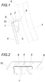
- a stripping element according to the invention has a steel beam 1 and a stripping strip 2 made of sintered hard metal which covers the steel beam 1 and is connected to the steel beam 1 by an adhesive layer 3.
- the steel girders 1 are fastened to support arms 4 with the aid of screws 5.
- the individual stripping elements lined up next to one another are each supported by the support arms 4 on a support shaft with which the stripping elements are pressed resiliently against a conveyor belt 6 in the region of a deflecting roller 7.
- the scraper strips 2 of the individual scraper elements complement each other to form a scraper strip that extends across the belt width, so that the conveyor belt 6 can be cleaned accordingly across its width with the help of the scraper edge 8 of the individual scraper strips 2.
- the stripping strip 2 of each stripping element on its side facing the steel beam 1 forms an undercut receiving groove 9 which is continuous in the longitudinal direction and in which the steel beam 1 engages, forming an adhesive gap which is filled with the adhesive layer 3, so that between the stripping strip 2 Sintered hard metal and the steel carrier 1 via the adhesive layer 3 results in a form-fitting and force-fitting connection which advantageously satisfies the loads occurring when cleaning a conveyor belt 6.
- the main loads on the wiper elements occurring essentially transversely to the wiper bar 2 are transferred from the wiper bar 2 to the steel carrier 1 via the form fit of the steel girder 1 engaging in the undercut receiving groove 9, without particularly stressing the adhesion of the adhesive layer 3 between the wiper bar 2 and steel girder 1 .
- the adhesive connection between the wiper strip 2 and the steel girder 1 comes into play above all when it comes to transferring loads acting in the longitudinal direction of the squeegee bar 2 to the steel girder. These loads can easily be absorbed by the adhesive layer 3 because these loads turn out to be comparatively low.
- the scraper strips 2 made of hard metal are designed in such a way that their longitudinal edge section 10 on the side of the receiving groove 9 opposite the scraping edge 8 is the end face of the screwed onto the steel girders 1
- Support arms 4 covers, like this of the Fig. 1 can be taken. This measure ensures that the support arms 4 are largely protected from wear by the material detached from the conveyor belt 6 with the aid of the scraper strips 2.
Landscapes
- Engineering & Computer Science (AREA)
- Mechanical Engineering (AREA)
- Belt Conveyors (AREA)
- Rollers For Roller Conveyors For Transfer (AREA)
Abstract
Description
- Die Erfindung bezieht sich auf ein Abstreifelement für ein Förderband mit einem Stahlträger, auf dem eine Abstreifleiste aus gesintertem Hartmetall mittels einer Klebeschicht befestigt ist.
- Um die Abstreifleiste aus gesintertem Hartmetall eines Abstreifelements für ein Förderband vorteilhaft mit dem sie aufnehmenden Stahlträger verbinden zu können, ist es bekannt, die Abstreifleiste mithilfe eines Silberlots auf den Stahlträger aufzulöten. Versuche, die teure Lötverbindung durch eine Klebeverbindung zu ersetzen, zeitigten jedoch nicht das angestrebte Ergebnis, weil mit herkömmlichen Klebeverbindungen nicht die für solche Abstreifelemente geforderte Standfestigkeit erreicht werden konnte, und zwar auch dann nicht, wenn die Abstreifleiste aus Hartmetall mit dem Stahlträger zusätzlich verschraubt wurde.
- Der Erfindung liegt somit die Aufgabe zugrunde, eine Klebeverbindung zwischen der Abstreifleiste aus gesintertem Hartmetall und dem Stahlträger eines Abstreifelements für ein Förderband so auszugestalten, dass eine vorteilhafte Standfestigkeit der Verbindung gewährleistet werden kann, ohne einen zusätzlichen Aufwand zur Herstellung der Verbindung in Kauf nehmen zu müssen.
- Ausgehend von einem Abstreifelement der eingangs geschilderten Art löst die Erfindung die gestellte Aufgabe dadurch, dass die Abstreifleiste auf ihrer dem Stahlträger zugekehrten Seite eine in Längsrichtung durchgehende, hinterschnittene Aufnahmenut bildet, in die der Stahlträger unter Ausbildung eines die Klebeschicht aufnehmenden Klebespalts formschlüssig eingreift.
- Durch die formschlüssige Aufnahme des Stahlträgers in der den Klebebereich vorgebenden Aufnahmenut der Abstreifleiste werden die quer zur Abstreifleiste wirkenden Kräfte auf den Stahlträger übertragen, ohne die Klebeverbindung übermäßig zu beanspruchen. Über die Klebeverbindung müssen im Wesentlichen nur die in Längsrichtung der Abstreifleiste wirksamen Belastungen der Abstreifleiste auf den Stahlträger abgetragen werden. Da beim Abstreifvorgang jedoch die Abstreifleiste insbesondere quer zu Längsrichtung belastet wird, wird durch die erfindungsgemäße Maßnahme eine Klebeverbindung sichergestellt, die allen bei solchen Abstreifelementen gegebenen Anforderungen gerecht werden kann. Das Vorsehen einer hinterschnittenen Aufnahmenut bedeutet für die Fertigung der Abstreifleiste aus gesintertem Hartmetall keinen entscheidenden Mehraufwand, weil beim Formpressen des für die Herstellung der Abstreifleiste eingesetzten Hartmetall-Sinterpulvers zu einem Sinterkörper diese Aufnahmenut mitgeformt wird. Eine nur schwierig durchführbare Nachbearbeitung der Aufnahmenut kann ja entfallen, weil die Fertigungstoleranzen durch den Klebespalt ausgeglichen werden.
- Besonders vorteilhafte Konstruktionsverhältnisse ergeben sich, wenn der Längsrandabschnitt der Abstreifleiste auf der einer Schabkante gegenüberliegenden Seite der Aufnahmenut die Stirnflächen von auf dieser Seite am Stahlträger festgeschraubten Stützarmen abdeckt, die den Stahlträger mit einer Trägerwelle verbinden. Die stirnseitige Abdeckung dieser Stützarme durch einen Längsrandabschnitt der Abstreifleiste aus Hartmetall schützt die Stützarme vor einem Verschleiß durch das von der Abstreifleiste vom Förderband gelöste Material.
- In der Zeichnung ist der Erfindungsgegenstand beispielsweise dargestellt. Es zeigen
-
Fig. 1 ein erfindungsgemäßes Abstreifelement eines Abstreifers in einer Ansicht in Längsrichtung der Abstreifleiste und -
Fig. 2 die mit dem Stahlträger durch eine Klebeschicht verbundene Abstreifleiste im Querschnitt in einem größeren Maßstab. - Ein erfindungsgemäßes Abstreifelement weist einen Stahlträger 1 und eine den Stahlträger 1 abdeckende Abstreifleiste 2 aus gesintertem Hartmetall auf, die mit dem Stahlträger 1 durch eine Klebeschicht 3 verbunden ist. Wie aus der
Fig. 1 ersichtlich ist, sind die Stahlträger 1 an Stützarmen 4 mithilfe von Schrauben 5 befestigt. Die einzelnen nebeneinandergereihten Abstreifelemente sind jeweils für sich durch die Stützarme 4 auf einer Tragwelle gelagert, mit der die Abstreifelemente federnd an ein Förderband 6 im Bereich einer Umlenkrolle 7 angedrückt werden. Die Abstreifleisten 2 der einzelnen Abstreifelemente ergänzen sich zu einer über die Bandbreite durchgehenden Schableiste, sodass mithilfe der Schabkante 8 der einzelnen Abstreifleisten 2 das Förderband 6 über seine Breite entsprechend gereinigt werden kann. - Wie insbesondere aus der
Fig. 2 hervorgeht, bildet die Abstreifleiste 2 jedes Abstreifelements auf ihrer dem Stahlträger 1 zugekehrten Seite eine in Längsrichtung durchgehende, hinterschnittene Aufnahmenut 9, in die der Stahlträger 1 unter Ausbildung eines Klebespalts eingreift, der mit der Klebeschicht 3 ausgefüllt ist, sodass sich zwischen der Abstreifleiste 2 aus gesintertem Hartmetall und dem Stahlträger 1 über die Klebeschicht 3 eine form- und kraftschlüssige Verbindung ergibt, die den beim Reinigen eines Förderbands 6 auftretenden Belastungen vorteilhaft genügt. Die im Wesentlichen quer zur Abstreifleiste 2 auftretenden Hauptbelastungen der Abstreifelemente werden ja über den Formschluss des in die hinterschnittene Aufnahmenut 9 eingreifenden Stahlträgers 1 von der Abstreifleiste 2 auf den Stahlträger 1 übertragen, ohne die Haftvermittlung der Klebeschicht 3 zwischen Abstreifleiste 2 und Stahlträger 1 besonders zu beanspruchen. Die Klebeverbindung zwischen der Abstreifleiste 2 und dem Stahlträger 1 kommt ja vor allem dann zur Wirkung, wenn es gilt, in Längsrichtung wirksame Belastungen der Abstreifleiste 2 auf den Stahlträger abzutragen. Diese Belastungen können durch die Klebeschicht 3 ohne Weiteres aufgenommen werden, weil diese Belastungen vergleichsweise gering ausfallen. - Die Abstreifleisten 2 aus Hartmetall sind derart ausgebildet, dass ihr Längsrandabschnitt 10 auf der der Schabkante 8 gegenüberliegenden Seite der Aufnahmenut 9 die Stirnseite der an den Stahlträgern 1 angeschraubten Stützarme 4 abdeckt, wie dies der
Fig. 1 entnommen werden kann. Durch diese Maßnahme wird sichergestellt, dass die Stützarme 4 vor einem Verschleiß durch das mithilfe der Abstreifleisten 2 vom Förderband 6 gelöste Material weitgehend geschützt werden.
Claims (2)
- Abstreifelement für ein Förderband (6) mit einem Stahlträger (1), auf dem eine Abstreifleiste (2) aus gesintertem Hartmetall mittels einer Klebeschicht (3) befestigt ist, dadurch gekennzeichnet, dass die Abstreifleiste (2) auf ihrer dem Stahlträger (1) zugekehrten Seite eine in Längsrichtung durchgehende, hinterschnittene Aufnahmenut (9) bildet, in die der Stahlträger (1) unter Ausbildung eines die Klebeschicht (3) aufnehmenden Klebespalts formschlüssig eingreift.
- Abstreifelement nach Anspruch 1, dadurch gekennzeichnet, dass der Längsrandabschnitt (10) der Abstreifleiste (2) auf der einer Schabkante (8) gegenüberliegenden Seite der Aufnahmenut (9) die Stirnflächen von auf dieser Seite am Stahlträger (1) festgeschraubten Stützarmen (4) abdeckt, die den Stahlträger (1) mit einer Trägerwelle verbinden.
Applications Claiming Priority (1)
| Application Number | Priority Date | Filing Date | Title |
|---|---|---|---|
| ATGM50106/2020U AT17164U1 (de) | 2020-05-20 | 2020-05-20 | Abstreifelement für ein Förderband |
Publications (3)
| Publication Number | Publication Date |
|---|---|
| EP3912934A1 true EP3912934A1 (de) | 2021-11-24 |
| EP3912934B1 EP3912934B1 (de) | 2023-08-02 |
| EP3912934C0 EP3912934C0 (de) | 2023-08-02 |
Family
ID=77389225
Family Applications (1)
| Application Number | Title | Priority Date | Filing Date |
|---|---|---|---|
| EP21162855.7A Active EP3912934B1 (de) | 2020-05-20 | 2021-03-16 | Abstreifelement für ein förderband |
Country Status (2)
| Country | Link |
|---|---|
| EP (1) | EP3912934B1 (de) |
| AT (1) | AT17164U1 (de) |
Citations (6)
| Publication number | Priority date | Publication date | Assignee | Title |
|---|---|---|---|---|
| EP0869090A2 (de) * | 1997-04-04 | 1998-10-07 | Dal Ferro, Bortolo Giulio | Abstreifvorrichtung zum Reinigen von Förderern |
| DE69719494T2 (de) * | 1997-07-18 | 2003-10-30 | Nippon Tsusho K.K., Tokio/Tokyo | Bandreiniger und dessen Kratzer |
| DE202004002967U1 (de) * | 2004-02-26 | 2004-05-13 | Schulmeistrat, Hans-Dieter | Gurtbandabstreifer mit Kunststoffsegmenten |
| DE60013937T2 (de) * | 1999-03-17 | 2005-01-27 | Martin Engineering Co., Neponset | Förderbandreiniger und -spannvorrichtung |
| EP2251282A1 (de) * | 2009-05-12 | 2010-11-17 | Peter Hoessl | Abstreifer für ein Förderband |
| DE202012010945U1 (de) * | 2012-11-05 | 2013-01-09 | F.E. Schulte Strathaus Gmbh & Co. Kg | Abstreifvorrichtung für Förderbänder |
Family Cites Families (2)
| Publication number | Priority date | Publication date | Assignee | Title |
|---|---|---|---|---|
| DE3930204A1 (de) * | 1989-09-09 | 1991-03-21 | Vsr Engineering Gmbh | Abstreifvorrichtung zum reinigen von foerderbaendern |
| CN206502352U (zh) * | 2017-02-27 | 2017-09-19 | 北京高强亿圆混凝土有限责任公司 | 一种骨料输送机 |
-
2020
- 2020-05-20 AT ATGM50106/2020U patent/AT17164U1/de unknown
-
2021
- 2021-03-16 EP EP21162855.7A patent/EP3912934B1/de active Active
Patent Citations (6)
| Publication number | Priority date | Publication date | Assignee | Title |
|---|---|---|---|---|
| EP0869090A2 (de) * | 1997-04-04 | 1998-10-07 | Dal Ferro, Bortolo Giulio | Abstreifvorrichtung zum Reinigen von Förderern |
| DE69719494T2 (de) * | 1997-07-18 | 2003-10-30 | Nippon Tsusho K.K., Tokio/Tokyo | Bandreiniger und dessen Kratzer |
| DE60013937T2 (de) * | 1999-03-17 | 2005-01-27 | Martin Engineering Co., Neponset | Förderbandreiniger und -spannvorrichtung |
| DE202004002967U1 (de) * | 2004-02-26 | 2004-05-13 | Schulmeistrat, Hans-Dieter | Gurtbandabstreifer mit Kunststoffsegmenten |
| EP2251282A1 (de) * | 2009-05-12 | 2010-11-17 | Peter Hoessl | Abstreifer für ein Förderband |
| DE202012010945U1 (de) * | 2012-11-05 | 2013-01-09 | F.E. Schulte Strathaus Gmbh & Co. Kg | Abstreifvorrichtung für Förderbänder |
Also Published As
| Publication number | Publication date |
|---|---|
| EP3912934B1 (de) | 2023-08-02 |
| EP3912934C0 (de) | 2023-08-02 |
| AT17164U1 (de) | 2021-07-15 |
Similar Documents
| Publication | Publication Date | Title |
|---|---|---|
| DE3608193C2 (de) | ||
| DE102008011449B4 (de) | Wischarm/Wischblattverbindung | |
| DE3304053A1 (de) | Bandpassfilter | |
| DE1530993C3 (de) | Wischblatt für Fahrzeugscheiben | |
| DE19743210A1 (de) | Klinge | |
| DE69515715T2 (de) | Farbstrahlaufzeichnungskopf | |
| EP3912934B1 (de) | Abstreifelement für ein förderband | |
| AT524317A4 (de) | Abstreifleiste und Bausatz zur Verwendung in einer Anlage zur Erzeugung einer Papierbahn | |
| DE418116T1 (de) | Metallische verstaerkung fuer leiste oder dichtung, insbesondere fuer die kraftfahrzeugindustrie. | |
| DE102010005274A1 (de) | Wischblatt, Adapter sowie Werkzeugvorrichtung zum Herstellen eines Adapters | |
| EP0135544B1 (de) | Entwässerungselement für den nassteil einer papiermaschine | |
| EP3747655B1 (de) | Druckkopf und verfahren zur herstellung eines druckkopfs | |
| DE2856709A1 (de) | Schaber fuer papiermaschinen | |
| AT505661B1 (de) | Abstreifer für ein förderband | |
| DE3210392C1 (de) | Verbindung zum Endlosmachen von Förderbändern | |
| AT16966U1 (de) | Reinigungsbürste für ein Förderband | |
| EP1881107A1 (de) | Siebleiste für Papiererzeugungsanlagen | |
| DE2325147C3 (de) | Scheibenwischerblatt für Kraftfahrzeuge | |
| DE3841133A1 (de) | Scheibenwischerblatt | |
| DE10210453B4 (de) | Verfahren zur Herstellung von Seiherstäben, Seiherstab mit Distanzelement sowie Vorrichtung zum Abpressen | |
| EP2251282A1 (de) | Abstreifer für ein Förderband | |
| AT503589B1 (de) | Träger mit verschleissteilen für schneckenpressen | |
| EP3741714A1 (de) | Abstreifvorrichtung für förderbänder | |
| DE4407657C2 (de) | Abstreifvorrichtung mit einer Leiste aus einem schlagzähen, keramischen Kunststoff | |
| EP2574575B1 (de) | Abstreifer für ein Förderband |
Legal Events
| Date | Code | Title | Description |
|---|---|---|---|
| PUAI | Public reference made under article 153(3) epc to a published international application that has entered the european phase |
Free format text: ORIGINAL CODE: 0009012 |
|
| STAA | Information on the status of an ep patent application or granted ep patent |
Free format text: STATUS: THE APPLICATION HAS BEEN PUBLISHED |
|
| AK | Designated contracting states |
Kind code of ref document: A1 Designated state(s): AL AT BE BG CH CY CZ DE DK EE ES FI FR GB GR HR HU IE IS IT LI LT LU LV MC MK MT NL NO PL PT RO RS SE SI SK SM TR |
|
| B565 | Issuance of search results under rule 164(2) epc |
Effective date: 20210810 |
|
| STAA | Information on the status of an ep patent application or granted ep patent |
Free format text: STATUS: REQUEST FOR EXAMINATION WAS MADE |
|
| 17P | Request for examination filed |
Effective date: 20220520 |
|
| RBV | Designated contracting states (corrected) |
Designated state(s): AL AT BE BG CH CY CZ DE DK EE ES FI FR GB GR HR HU IE IS IT LI LT LU LV MC MK MT NL NO PL PT RO RS SE SI SK SM TR |
|
| RIC1 | Information provided on ipc code assigned before grant |
Ipc: B65G 45/12 20060101AFI20230201BHEP |
|
| GRAP | Despatch of communication of intention to grant a patent |
Free format text: ORIGINAL CODE: EPIDOSNIGR1 |
|
| STAA | Information on the status of an ep patent application or granted ep patent |
Free format text: STATUS: GRANT OF PATENT IS INTENDED |
|
| INTG | Intention to grant announced |
Effective date: 20230317 |
|
| GRAS | Grant fee paid |
Free format text: ORIGINAL CODE: EPIDOSNIGR3 |
|
| GRAA | (expected) grant |
Free format text: ORIGINAL CODE: 0009210 |
|
| STAA | Information on the status of an ep patent application or granted ep patent |
Free format text: STATUS: THE PATENT HAS BEEN GRANTED |
|
| AK | Designated contracting states |
Kind code of ref document: B1 Designated state(s): AL AT BE BG CH CY CZ DE DK EE ES FI FR GB GR HR HU IE IS IT LI LT LU LV MC MK MT NL NO PL PT RO RS SE SI SK SM TR |
|
| REG | Reference to a national code |
Ref country code: GB Ref legal event code: FG4D Free format text: NOT ENGLISH |
|
| REG | Reference to a national code |
Ref country code: CH Ref legal event code: EP |
|
| REG | Reference to a national code |
Ref country code: DE Ref legal event code: R096 Ref document number: 502021001120 Country of ref document: DE |
|
| REG | Reference to a national code |
Ref country code: IE Ref legal event code: FG4D Free format text: LANGUAGE OF EP DOCUMENT: GERMAN |
|
| U01 | Request for unitary effect filed |
Effective date: 20230802 |
|
| U07 | Unitary effect registered |
Designated state(s): AT BE BG DE DK EE FI FR IT LT LU LV MT NL PT SE SI Effective date: 20230807 |
|
| PG25 | Lapsed in a contracting state [announced via postgrant information from national office to epo] |
Ref country code: GR Free format text: LAPSE BECAUSE OF FAILURE TO SUBMIT A TRANSLATION OF THE DESCRIPTION OR TO PAY THE FEE WITHIN THE PRESCRIBED TIME-LIMIT Effective date: 20231103 |
|
| PG25 | Lapsed in a contracting state [announced via postgrant information from national office to epo] |
Ref country code: IS Free format text: LAPSE BECAUSE OF FAILURE TO SUBMIT A TRANSLATION OF THE DESCRIPTION OR TO PAY THE FEE WITHIN THE PRESCRIBED TIME-LIMIT Effective date: 20231202 |
|
| PG25 | Lapsed in a contracting state [announced via postgrant information from national office to epo] |
Ref country code: RS Free format text: LAPSE BECAUSE OF FAILURE TO SUBMIT A TRANSLATION OF THE DESCRIPTION OR TO PAY THE FEE WITHIN THE PRESCRIBED TIME-LIMIT Effective date: 20230802 Ref country code: NO Free format text: LAPSE BECAUSE OF FAILURE TO SUBMIT A TRANSLATION OF THE DESCRIPTION OR TO PAY THE FEE WITHIN THE PRESCRIBED TIME-LIMIT Effective date: 20231102 Ref country code: IS Free format text: LAPSE BECAUSE OF FAILURE TO SUBMIT A TRANSLATION OF THE DESCRIPTION OR TO PAY THE FEE WITHIN THE PRESCRIBED TIME-LIMIT Effective date: 20231202 Ref country code: HR Free format text: LAPSE BECAUSE OF FAILURE TO SUBMIT A TRANSLATION OF THE DESCRIPTION OR TO PAY THE FEE WITHIN THE PRESCRIBED TIME-LIMIT Effective date: 20230802 Ref country code: GR Free format text: LAPSE BECAUSE OF FAILURE TO SUBMIT A TRANSLATION OF THE DESCRIPTION OR TO PAY THE FEE WITHIN THE PRESCRIBED TIME-LIMIT Effective date: 20231103 |
|
| PG25 | Lapsed in a contracting state [announced via postgrant information from national office to epo] |
Ref country code: PL Free format text: LAPSE BECAUSE OF FAILURE TO SUBMIT A TRANSLATION OF THE DESCRIPTION OR TO PAY THE FEE WITHIN THE PRESCRIBED TIME-LIMIT Effective date: 20230802 |
|
| PG25 | Lapsed in a contracting state [announced via postgrant information from national office to epo] |
Ref country code: ES Free format text: LAPSE BECAUSE OF FAILURE TO SUBMIT A TRANSLATION OF THE DESCRIPTION OR TO PAY THE FEE WITHIN THE PRESCRIBED TIME-LIMIT Effective date: 20230802 |
|
| PG25 | Lapsed in a contracting state [announced via postgrant information from national office to epo] |
Ref country code: SM Free format text: LAPSE BECAUSE OF FAILURE TO SUBMIT A TRANSLATION OF THE DESCRIPTION OR TO PAY THE FEE WITHIN THE PRESCRIBED TIME-LIMIT Effective date: 20230802 Ref country code: RO Free format text: LAPSE BECAUSE OF FAILURE TO SUBMIT A TRANSLATION OF THE DESCRIPTION OR TO PAY THE FEE WITHIN THE PRESCRIBED TIME-LIMIT Effective date: 20230802 Ref country code: ES Free format text: LAPSE BECAUSE OF FAILURE TO SUBMIT A TRANSLATION OF THE DESCRIPTION OR TO PAY THE FEE WITHIN THE PRESCRIBED TIME-LIMIT Effective date: 20230802 Ref country code: CZ Free format text: LAPSE BECAUSE OF FAILURE TO SUBMIT A TRANSLATION OF THE DESCRIPTION OR TO PAY THE FEE WITHIN THE PRESCRIBED TIME-LIMIT Effective date: 20230802 Ref country code: SK Free format text: LAPSE BECAUSE OF FAILURE TO SUBMIT A TRANSLATION OF THE DESCRIPTION OR TO PAY THE FEE WITHIN THE PRESCRIBED TIME-LIMIT Effective date: 20230802 |
|
| U20 | Renewal fee for the european patent with unitary effect paid |
Year of fee payment: 4 Effective date: 20240325 |
|
| REG | Reference to a national code |
Ref country code: DE Ref legal event code: R097 Ref document number: 502021001120 Country of ref document: DE |
|
| PLBE | No opposition filed within time limit |
Free format text: ORIGINAL CODE: 0009261 |
|
| STAA | Information on the status of an ep patent application or granted ep patent |
Free format text: STATUS: NO OPPOSITION FILED WITHIN TIME LIMIT |
|
| 26N | No opposition filed |
Effective date: 20240503 |
|
| REG | Reference to a national code |
Ref country code: CH Ref legal event code: PL |
|
| PG25 | Lapsed in a contracting state [announced via postgrant information from national office to epo] |
Ref country code: MC Free format text: LAPSE BECAUSE OF FAILURE TO SUBMIT A TRANSLATION OF THE DESCRIPTION OR TO PAY THE FEE WITHIN THE PRESCRIBED TIME-LIMIT Effective date: 20230802 |
|
| PG25 | Lapsed in a contracting state [announced via postgrant information from national office to epo] |
Ref country code: MC Free format text: LAPSE BECAUSE OF FAILURE TO SUBMIT A TRANSLATION OF THE DESCRIPTION OR TO PAY THE FEE WITHIN THE PRESCRIBED TIME-LIMIT Effective date: 20230802 |
|
| PG25 | Lapsed in a contracting state [announced via postgrant information from national office to epo] |
Ref country code: IE Free format text: LAPSE BECAUSE OF NON-PAYMENT OF DUE FEES Effective date: 20240316 |
|
| PG25 | Lapsed in a contracting state [announced via postgrant information from national office to epo] |
Ref country code: IE Free format text: LAPSE BECAUSE OF NON-PAYMENT OF DUE FEES Effective date: 20240316 Ref country code: CH Free format text: LAPSE BECAUSE OF NON-PAYMENT OF DUE FEES Effective date: 20240331 |
|
| U20 | Renewal fee for the european patent with unitary effect paid |
Year of fee payment: 5 Effective date: 20250324 |
|
| PGFP | Annual fee paid to national office [announced via postgrant information from national office to epo] |
Ref country code: CH Payment date: 20250401 Year of fee payment: 5 |
|
| PG25 | Lapsed in a contracting state [announced via postgrant information from national office to epo] |
Ref country code: CY Free format text: LAPSE BECAUSE OF FAILURE TO SUBMIT A TRANSLATION OF THE DESCRIPTION OR TO PAY THE FEE WITHIN THE PRESCRIBED TIME-LIMIT; INVALID AB INITIO Effective date: 20210316 |
|
| PG25 | Lapsed in a contracting state [announced via postgrant information from national office to epo] |
Ref country code: HU Free format text: LAPSE BECAUSE OF FAILURE TO SUBMIT A TRANSLATION OF THE DESCRIPTION OR TO PAY THE FEE WITHIN THE PRESCRIBED TIME-LIMIT; INVALID AB INITIO Effective date: 20210316 |
|
| GBPC | Gb: european patent ceased through non-payment of renewal fee |
Effective date: 20250316 |
|
| PG25 | Lapsed in a contracting state [announced via postgrant information from national office to epo] |
Ref country code: TR Free format text: LAPSE BECAUSE OF FAILURE TO SUBMIT A TRANSLATION OF THE DESCRIPTION OR TO PAY THE FEE WITHIN THE PRESCRIBED TIME-LIMIT Effective date: 20230802 |
|
| PG25 | Lapsed in a contracting state [announced via postgrant information from national office to epo] |
Ref country code: GB Free format text: LAPSE BECAUSE OF NON-PAYMENT OF DUE FEES Effective date: 20250316 |
|
| REG | Reference to a national code |
Ref country code: CH Ref legal event code: U11 Free format text: ST27 STATUS EVENT CODE: U-0-0-U10-U11 (AS PROVIDED BY THE NATIONAL OFFICE) Effective date: 20260401 |
|
| U20 | Renewal fee for the european patent with unitary effect paid |
Year of fee payment: 6 Effective date: 20260324 |