EP3914380B1 - Saturateur pour la production d'une boisson gazeuse - Google Patents
Saturateur pour la production d'une boisson gazeuse Download PDFInfo
- Publication number
- EP3914380B1 EP3914380B1 EP21709939.9A EP21709939A EP3914380B1 EP 3914380 B1 EP3914380 B1 EP 3914380B1 EP 21709939 A EP21709939 A EP 21709939A EP 3914380 B1 EP3914380 B1 EP 3914380B1
- Authority
- EP
- European Patent Office
- Prior art keywords
- valve
- carbonator
- venting
- actuator
- operating mechanism
- Prior art date
- Legal status (The legal status is an assumption and is not a legal conclusion. Google has not performed a legal analysis and makes no representation as to the accuracy of the status listed.)
- Active
Links
Images


Classifications
-
- B—PERFORMING OPERATIONS; TRANSPORTING
- B01—PHYSICAL OR CHEMICAL PROCESSES OR APPARATUS IN GENERAL
- B01F—MIXING, e.g. DISSOLVING, EMULSIFYING OR DISPERSING
- B01F23/00—Mixing according to the phases to be mixed, e.g. dispersing or emulsifying
- B01F23/20—Mixing gases with liquids
- B01F23/23—Mixing gases with liquids by introducing gases into liquid media, e.g. for producing aerated liquids
- B01F23/236—Mixing gases with liquids by introducing gases into liquid media, e.g. for producing aerated liquids specially adapted for aerating or carbonating beverages
- B01F23/2364—Mixing gases with liquids by introducing gases into liquid media, e.g. for producing aerated liquids specially adapted for aerating or carbonating beverages using security elements, e.g. valves, for relieving overpressure
-
- A—HUMAN NECESSITIES
- A23—FOODS OR FOODSTUFFS; TREATMENT THEREOF, NOT COVERED BY OTHER CLASSES
- A23L—FOODS, FOODSTUFFS OR NON-ALCOHOLIC BEVERAGES, NOT OTHERWISE PROVIDED FOR; PREPARATION OR TREATMENT THEREOF
- A23L2/00—Non-alcoholic beverages; Dry compositions or concentrates therefor; Preparation or treatment thereof
- A23L2/52—Adding ingredients
- A23L2/54—Mixing with gases
-
- B—PERFORMING OPERATIONS; TRANSPORTING
- B01—PHYSICAL OR CHEMICAL PROCESSES OR APPARATUS IN GENERAL
- B01F—MIXING, e.g. DISSOLVING, EMULSIFYING OR DISPERSING
- B01F23/00—Mixing according to the phases to be mixed, e.g. dispersing or emulsifying
- B01F23/20—Mixing gases with liquids
- B01F23/23—Mixing gases with liquids by introducing gases into liquid media, e.g. for producing aerated liquids
- B01F23/236—Mixing gases with liquids by introducing gases into liquid media, e.g. for producing aerated liquids specially adapted for aerating or carbonating beverages
- B01F23/2361—Mixing gases with liquids by introducing gases into liquid media, e.g. for producing aerated liquids specially adapted for aerating or carbonating beverages within small containers, e.g. within bottles
-
- B—PERFORMING OPERATIONS; TRANSPORTING
- B01—PHYSICAL OR CHEMICAL PROCESSES OR APPARATUS IN GENERAL
- B01F—MIXING, e.g. DISSOLVING, EMULSIFYING OR DISPERSING
- B01F23/00—Mixing according to the phases to be mixed, e.g. dispersing or emulsifying
- B01F23/20—Mixing gases with liquids
- B01F23/23—Mixing gases with liquids by introducing gases into liquid media, e.g. for producing aerated liquids
- B01F23/237—Mixing gases with liquids by introducing gases into liquid media, e.g. for producing aerated liquids characterised by the physical or chemical properties of gases or vapours introduced in the liquid media
- B01F23/2376—Mixing gases with liquids by introducing gases into liquid media, e.g. for producing aerated liquids characterised by the physical or chemical properties of gases or vapours introduced in the liquid media characterised by the gas being introduced
- B01F23/23762—Carbon dioxide
- B01F23/237621—Carbon dioxide in beverages
-
- B—PERFORMING OPERATIONS; TRANSPORTING
- B01—PHYSICAL OR CHEMICAL PROCESSES OR APPARATUS IN GENERAL
- B01F—MIXING, e.g. DISSOLVING, EMULSIFYING OR DISPERSING
- B01F35/00—Accessories for mixers; Auxiliary operations or auxiliary devices; Parts or details of general application
- B01F35/60—Safety arrangements
- B01F35/602—Safety arrangements with a safety or relief valve
-
- B—PERFORMING OPERATIONS; TRANSPORTING
- B01—PHYSICAL OR CHEMICAL PROCESSES OR APPARATUS IN GENERAL
- B01F—MIXING, e.g. DISSOLVING, EMULSIFYING OR DISPERSING
- B01F2101/00—Mixing characterised by the nature of the mixed materials or by the application field
- B01F2101/06—Mixing of food ingredients
- B01F2101/14—Mixing of ingredients for non-alcoholic beverages; Dissolving sugar in water
Definitions
- the present disclosure relates to a carbonator for producing carbonated beverage, such as carbonated water.
- Carbonators are used for producing carbonated beverage, such as carbonated water.
- Carbonators for domestic use are typically designed to be placed on a table or bench and are operated manually by a person or user.
- a carbonator a.k.a. a soda water machine
- Such a carbonator typically comprises a carbon dioxide bottle, which is connected to a nozzle which is inserted into a water bottle that contains liquid.
- the carbonator further comprises an operating arrangement, which allows the user to open a valve in the carbon dioxide bottle to introduce carbon dioxide into the water bottle.
- the carbon dioxide dissolves in the liquid in the water bottle (under pressure).
- the operating arrangement typically comprises a lever, or button, to be maneuvered by the user as well as tubes and various valves to regulate the pressure of carbon dioxide in the water bottle.
- the Chinese utility model CN 204218672 U shows a carbonator with a water bottle 1 and a carbon dioxide bottle 2 which is connected to the water bottle via an opening valve 7.
- the carbonator further has a first release valve 13 for releasing excess pressure from the water bottle 1 after completed carbonation.
- the release valve 13 and the opening valve 7 of the carbon dioxide bottle are connected by a bridge 8 to ensure that the release valve 13 is open when the opening valve 7 of the carbon dioxide bottle is closed. Thereby, it is ensured that the bottle is vented prior to removal.
- Operation of the carbonator is achieved by a lever, which is connected to the bridge 8 via a complicated and voluminous mechanism that includes toothed wheels 20, 21 and linkage arms 23.
- the Swedish patent application SE 0950129 A1 describes a carbonator which aims at reducing the carbon dioxide consumption during repeated carbonation cycles.
- the carbonator comprises a special valve 14 which is arranged in the water bottle 1 and that is actuated by an operating mechanism 12, which connected to an opening valve 7 of the carbon dioxide bottle 6 and to the valve 14.
- the valve 14 comprises a valve piston 16 and a spring 22 and a maneuver element 21, which may be actuated by the operating mechanism 12.
- the valve 14 works or otherwise operates as an overpressure valve as long as the operating mechanism 12 bears on the maneuver element 21.
- Yet a further object of the present disclosure is to present a carbonator, which is reliable in service.
- a further object of the present disclosure is to present a carbonator, which is suitable for domestic use.
- present disclosure presents a carbonator for producing carbonated beverage according to the appended independent claim 1. Furthermore, present disclosure presents advantageous embodiments as defined in the appended dependent claims.
- a carbonator for producing carbonated beverage comprising:
- the operating mechanism 80 may be configured such that the duration of the intermediate mode II is longer than the duration of the start mode I. This makes the intermediate mode II easy to find for the person operating the carbonator and avoids involuntary venting of the beverage bottle.
- the venting valve 40 comprises a sleeve 41 with a movable valve body 44 and an actuator 46 arranged to be moved axially in the sleeve 41 by the operating mechanism 80 towards the valve body 44 to set the venting valve 40 in the open state.
- the CO2-valve 12 comprises a sleeve 14 with an actuator 13, wherein the actuator 13 is arranged to be moved axially in the sleeve 14 by the operating mechanism 80 into the first connector 11 thereby setting the CO2-valve 12 in an open state.
- the use of such actuator/sleeve valves provides an advantage in that CO2-valve may fit CO2-bottles with different types of outlet valves and length or size of opening pins.
- the operating mechanism 80 may comprise a bridge 85 that is rotationally journalled in the carbonator 100 and connected to the manipulator 103 such that the bridge 85 may be rotated by the manipulator 103 around a rotational axis Y extending through the bridge 85 and through the manipulator 103.
- the bridge 85 may comprise a venting surface 86 which is in contact with the actuator 46 of the venting valve 40 and a CO2-surface 90 which is in contact with the actuator 13 of the CO2-valve 12.
- the bridge is of simple construction and has few movable parts that may stick or jam. This allows for a compact and failsafe construction of the carbonator.
- the operating mechanism 80 may further be arranged such that rotational movement of the operating mechanism 80 in a first direction displaces the venting surface 86 and the CO2-surface 90 relative the actuator 46 of the venting valve 40 and the actuator 13 of the CO2-valve such that the venting surface 86 forces the actuator 46 to set the venting valve 40 in an open state and the CO2-surface 90 forces the actuator 13 to set the CO2-valve 12 in an open state, and vice versa.
- the use of cooperating venting surfaces and CO2 surface allows for easy and failsafe simultaneous operation of the venting valve and the CO2-valve.
- venting surface 86 and the CO2-surface 90 may be oriented in a side-by-side manner along or parallel to, the rotational axis Y.
- the bridge thereby occupies a minimum of space.
- the venting surface 86 comprises a first end surface 87 and a second end surface 88 with different configuration, wherein;
- the CO2-surface 90 may be arranged to:
- the manipulator 103 may be a lever, wherein the operating mechanism 80 is configured to be:
- the manipulator 103 may be connected to the bridge 85 via a rotational damper 84.
- the rotational damper stabilizes the motion of the lever which in turn makes it easier to place and hold the operational mechanism 80 in the intermediate mode III.
- the rotational damper also avoids splashes of water through the venting valve during venting of the beverage container. This, because the damper 84 is connected to the bridge 85 and therefor retards the velocity by which the venting valve 40 and the CO2 12 valve may open and close.
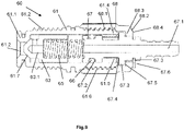
- the carbonator may comprise a first over-pressure valve 60 arranged to relieve over-pressure in a beverage container 107.
- the over-pressure valve 60 may comprise a sleeve 61 with a first end 61.1 connectable to the second connector 32 so that fluid may flow from the mouth 108 of a beverage container 107 in the second connector 32 into the first end 61.1 of said into first over-pressure valve 60.
- the sleeve 61 having a second end 61.4 with an opening 64.5.
- the over-pressure valve further comprises fluid conduit connector 67 for connection with a fluid drain 72 arranged within the sleeve 61 and partially extending out through said opening 64.5, and a movable valve body 63 with a fluid channel 63.1 arranged within the sleeve 61 and supported against the fluid conduit connector 67 by a compressible biasing element 65.
- An adjustment ring 68 may be turnable arranged on the second end 61.4 of the sleeve 61 and engages the fluid conduit connector 67 such that turning of the adjustment ring 68 moves the fluid conduit connector 67 towards or away from the valve body 63 and thereby causes the biasing element 65 to expand or compress.
- overpressure valve makes possible to adjust the spring force of the biasing element 65 and thereby the release pressure of the over pressure valve 60.
- a further advantage of the overpressure valve is that it may be fluid tight connected to a resilient draining pipe. This in turn avoids unwanted leakage of water through the over pressure valve.
- a second aspect of the present disclosure relates to an over-pressure valve 60 comprising a sleeve 61 with a first end 61.1 connectable to the second connector 32 so that fluid may flow from the mouth 108 of a beverage container 107 in the second connector 32 into the first end 61.1 of said over-pressure valve 60 and;
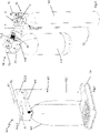
- FIG. 1 shows a carbonator 100 according to a first alternative of the present disclosure.
- the carbonator 100 comprises a base 101 for supporting the carbonator on a surface, such as a table or bench.
- a housing 102 extends upwards from the base 101.
- Housing 102 has a lower cylindrical portion 102.1 which may accommodate a CO2-container and an upper portion 102.2 which may accommodate a carbonation arrangement (which will be described later).
- the housing 102 further comprises a distal portion 102.3, which extends from the upper portion 102.2 of the housing.
- a manipulator 103 in the form of a lever, extends from the upper portion 102.2 of the housing 102 so that it is accessible to a person.
- a beverage container 107 for containing a liquid to be carbonated extends from the distal portion 102.3 of the housing 102.
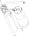
- Figure 2 shows a stripped view of the carbonator of figure 1 .
- the carbonator 100 comprises a first connector 11 for a gas-outlet of the CO2-container and second connector 32 for a mouth 108 of the beverage container 107 and a CO2-valve 12 for operating the CO2-container 104, and a first over-pressure valve 60 and second over-pressure valve 70 both for letting CO2-gas out of the beverage container 107 and a venting valve 40 operable to release pressure out of the beverage container.
- a first fluid conduit 71.1 such as a rubber hose, connects the CO2-valve 12 with the dissolver nozzle 31 (not shown).
- a second fluid conduit 71.2 connects the second connector 32 with the venting valve 40 and a third fluid conduit 71.3 connects the first over-pressure valve 60 to a drain 72.
- the carbonator has a CO2-head 10 and a dissolver head 30 that are spaced apart from each other.
- the dissolver head 30 has thereby the second connector 32 for a mouth 108 of a beverage container 107 and the dissolver nozzle 31.
- the CO2-head has the first connector 11, the CO2-valve 12, the venting valve 40 and an operating mechanism 80 (not shown, but which will be described further below).
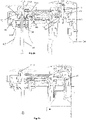
- Figure 2a shows a cross-sectional view along the line XI - X2 of the carbonator shown in figure 1 .
- Figure 2b shows a cross-sectional view along the line XI - X3 of the carbonator shown in figure.
- FIG 2a shows in cross-section the upper portion of the carbonator 100 of the present disclosure.
- the first connector 11 may comprise an opening 17 with an inner thread for screw-connection with the gas-outlet 105 a CO2-container 104.
- the second connector 32 may comprise an opening 34 with an inner thread for screw connection to an outer thread on the mouth 108 of the beverage container 107.
- other types of connectors are feasible for one or both of the opening 17 in the first connector and the opening 34 in second connector 32.
- bayonet connectors are feasible for one or both of the opening 17 in the first connector and the opening 34 in second connector 32.
- a dissolver nozzle 31 extends through the opening 34 of the second connector 32. The dissolver nozzle 31 may thereby extend through the mouth 108 of a beverage container 107 connected to the second connector 32.
- the dissolver nozzle 31 is connected to the CO2-valve 12 via the first fluid conduit 71.1 which is connected to a CO2-outlet 16 of the CO-valve 12.
- the CO2-valve 12 is arranged to be operated between a closed state, in which no CO2-gas enters the CO2-valve 12, and an open state in which CO2-gas may be introduced from the gas-outlet 105 of the CO2-container 104 into the CO2-valve 12 and further to the dissolver nozzle 31.
- the first over-pressure valve 60 which is connected to the opening 34 in the second connector 32 by a fourth fluid conduct 71.4 which may be formed in the second connector 32.
- the overpressure valve 60 which will be described later, is configured to open when the pressure in the beverage container 107 exceeds a first predetermined value, for example 5 - 6 bar. Also shown in figure 2a is the second over-pressure valve 70 which may be connected to the opening 34 in the second connector 32 by a fifth fluid conduit 71.5. The second over pressure valve 70 is configured to open when the pressure in the beverage container exceeds a second predetermined pressure, for example 12 bar. This type of valve is known in the art and need not to be described further here within.
- Figure 2b shows the venting valve 40 which is arranged to be operated between an open and closed state.
- excess CO2-gas may be led out from the beverage container 107 through fluid connector 71.2 and out through the venting valve 40.
- the closed state no excess CO2-gas may be led from the beverage container 107 through the venting valve 40.
- the venting valve 40 is shown in detail in figure 7b .
- the venting valve 40 comprises a sleeve 41, which may be a separate sleeve or formed by a portion of the second connector 32.
- An excess CO2-inlet 42 is formed in the wall of the sleeve 41.
- the excess CO2-inlet 42 is connected by fluid connector 71.2 to the opening 34 of the second connector 32 (see figure 2a ).
- the venting valve 40 comprises an outlet 43 which may be open to the atmosphere, in this case connected to a drain pipe 71.6 (see figure 2 ).
- a valve body 44 is movable arranged axially in the sleeve 41.
- the valve body 44 is biased towards a shoulder 47 in the first end of the sleeve 41 by biasing element 45 in the form of a pressure spring.
- the venting valve 40 further comprises an actuator 46, which may be rod-shaped, that is movable axially in the sleeve 40 towards and away from the valve body 44. Thus, the actuator 46 may be moved towards the valve body 44 such that the valve body 44 is moved away from the shoulder 47.
- the venting valve 40 is thereby set in an open mode in which excess CO2-gas may be led from the beverage container 107 through the excess CO2-opening 42 and out through the outlet 43 of the venting valve 40 (See figure 7c ).
- the valve body 44 moves, biased by the biasing element 45, against the shoulder 47.
- the venting valve 40 is thereby set in a closed state (see figure 7a ).
- the carbonator 100 comprises an operating mechanism 80 which is configured to operate the CO2-valve 12 and the venting valve 40 (not shown) between their respective open and closed positions.
- the CO2-surface 90 is realized as one side of a separate piece which in one end is connectable by a shackle 82 to a corresponding loop 89 on the bridge 85.
- the bridge 85 thereby comprises a through opening 93, through which the actuator 13 of the CO2-valve 12 may extend into contact with the CO2-surface 90.
- the operating mechanism 80 is further connectable to the aforementioned manipulator 103, in the shown embodiment a lever, such that a person may operate the operating mechanism 80 so that it pivots around an axis Y which extends through the two connections 81.1 81.2.
- the operating mechanism 80 may further comprise a rotational damper 84, which may be connected to the bridge 85 and to the manipulator 103 such that the rotational movement of the bridge 85 is retarded.
- Such rotational dampers are commercially available as rotation/rotary silicone dampers.
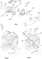
- FIG 5a shows the operating mechanism 90 in assembled state.
- the bridge 85 is pivoted by the manipulator 103. Rotational movement of the operating mechanism causes the bridge 85 to pivot.
- the venting surface 86 pivots and the CO2-surface 90 raises or lowers due to that it is connected in one end to the bridge 85 by the shackle 82.
- the venting surface 86 and the CO2-surface are arranged in a substantially side-by-side manner along the horizontal axis Y which may extend through the attachments 81.1, 81.2 of the bridge.
- the operating mechanism 80 is arranged such that rotational movement of the operating mechanism 80 in a first direction sets the venting valve 40 (not shown) in an open state and the CO2-valve 12 (not shown) in a closed state. Rotational movement of the operating mechanism 85 in the other direction sets the venting valve 40 (not shown) in a closed state and the CO2-valve 12 in an open state.
- the rotational movement of the operating mechanism, and thereby the bridge 85, is typically limited between a first end position A and a second end position D as indicated in figures 5a and 5b , respectively.
- Cross-sectional views of bridge and venting- and CO2-surfaces are shown in figures 7a, 8a .
- the operating mechanism 80 e.g. the venting surface 86 and the CO2-surface 90 thereof are configured such that the operating mechanism 80 (not shown) is:
- the handle shaped lever allows the person to easily find the different modes. It has shown that the person will using the carbonator learns to recognize the different modes in little time.
- the modes may be of different length. For example, the intermediate mode II may be longer than the start mode I.
- Figure 7a shows a cross-sectional view of the venting valve 40 and the portion of the bridge 85 that constitutes the venting surface 86.
- the venting surface 86 is a surface of the bridge 85 that is in contact with the actuator 46 of the venting valve 40.
- the venting surface 86 may comprise a first end surface 87 and a second end surface 88.
- the first end surface 87 may extend from the pivot point Y of the bridge 85 to the second end surface 88.
- the first and the second end surface 87, 88 are configured such they have different geometry.
- the first end surface 87 may be flat or have a radius that is greater than the radius of the second end surface 88.
- first and second end surfaces 87, 88 may also vary. In the embodiment shown in figures 7a - 7c , geometry and the lengths of the first and the second end surfaces 87, 88 are selected such that the distance between the venting surface 86 and the venting valve 40 (i.e. the top of the sleeve 41) varies in a predetermined manner during rotation of the bridge 85 and thereby causes the actuator 46 of the venting valve 40 to set the venting valve in closed or open position.
- the bridge 85 is in position A (see figure 6 ) in which the actuator 46 is in contact with the first end surface 87.
- the configuration of the first end surface 87 which may be substantially straight, results in a distance between the first end surface 87 and the venting valve 40 which is sufficiently small to force the actuator 46 against the valve body 44 so that the valve body is moved out of contact with the shoulder 47.
- the venting valve 40 is in open state when the bridge is in position A.
- the bridge 85 has pivoted to position D.
- the configuration of the second end surface 88 which may have a radius, results in a distance between the second end surface 88 and the venting valve 40 which is sufficiently great to allow the actuator 46 move out of contact with the valve body 44. This causes the valve body 44 to sealingly contact the shoulder 47 whereby the venting valve 40 is in closed mode.
- the venting valve 40 is in closed state when the bridge 85 is in position D and during pivoting of the bridge 85 from position B, over position C to position D.
- Figures 8a - 8c shows the corresponding movement of the CO2-surface 90 relative the actuator 13 of the CO2-valve 12.
- the bridge 85 (schematically indicated) is in position A (see figure 6 ) whereby the CO2-surface 90 is lowered such that the distance between CO2-surface 90 and the CO2-valve 12 (i.e. the sleeve 14) is sufficiently large to allow the actuator 13 to move out of contact with the valve body 106 of the CO2-container. Alternatively, to rest without exerting force on the valve body 106. The CO2-valve is thereby in closed state when the bridge is in position A.
- the bridge 85 has pivoted further to position C (see figure 6 ) thereby placing the CO2-surface 90 at a distance from the CO2-valve such that the actuator 13 is immediately prior to opening the valve 106 of the CO2-bottle.
- the CO2-valve is in closed state when the bridge 85 is in position C and during pivoting of the bridge 85 from position A, over position B to position C.
- configuration of the first and second end surfaces of the venting surface and the lifting motion of the CO2-surface have been by carefully selecting the in view of each other, in particular, in view of geometry and length. This in turn has made it possible to tailor the state of the respective venting- and CO2-valves and the duration of these states such that the three different operational modes I, II, III of the carbonator are achievable.
- the carbonator may comprise an over-pressure valve 60 that is coupled to the second connector 32 such that fluid may be led from the mouth of a beverage container 107 through the overpressure valve 60 and out into the atmosphere.
- the over-pressure valve 60 is shown in detail in figure 9 .
- the over-pressure valve 60 comprises a sleeve 61 with a first end 61.1 which is configured to be attached to the second connector 32.
- the first end 61.1 of the sleeve 61 may therefore be provided with an attachment portion 61.2 in the form of an outer thread.
- the second connector may be provided with a corresponding threaded bore (not shown).
- the first end 61.1 of the sleeve 61 has an opening 61.2 through which fluid may enter from the beverage bottle in the second connector 32 (not shown) into the sleeve 61.
- the sleeve 61 has further an opposite second end 61.4 with an opening 61.5.
- the opposite second end 61.4 may comprise an outer thread 61.6.
- a fluid conduit connector 67 for connection with a fluid drain is arranged within the sleeve 61 and may, as shown in figure 9 , have a male hose connector 67.1 which extends from the second opening 61.5 in the sleeve 61.
- the fluid conduit connector 67 is sealed against the inner surface of the sleeve 61 by a circumferential sealing element 66.
- the sealing element 66 is resilient and may be realized in the form of an O-ring, for example manufactured from rubber or silicone.
- the circumferential sealing element 66 may be received in a rear groove 67.2 in the fluid conduit connector 67.
- the fluid conduit connector 67 further comprises a forward flange 67.3 with a rear surface 67.4 which is directed towards the second opening 61.5 in the sleeve and a front surface 67.5.
- the fluid conduit connector further comprises a front flange 67.6 which may be realized as a piece of sheet metal (partly shown in figure 9 ) which is clipped into a front groove 67.7 of the fluid conduit connector 67.
- a valve body 63 is arranged within the sleeve 61, in the first end 61.1 thereof.
- the valve body 63 comprises a channel 63.1 which permits fluid to be led through the valve body 63.
- the valve body 63 is movable within the sleeve 61 and biased by one end of a compressible biasing member 65 in the form of a pressure spring against an abutment surface 61.7 on the first end 61.1 of the sleeve 61.
- the other end of the biasing member 65 is supported against the fluid conduit connector 67.
- valve body 63 is forced away from the abutment surface 61.7 to an open position in which pressurized fluid (water and/or CO2) may flow through the channel 63.1 in the valve body 63 and out through the fluid line connector 67.
- pressurized fluid water and/or CO2
- the biasing element 65 forces the valve body 63 back towards the abutment surface 61.7, whereby the over pressure valve is closed.
- the predetermined value is determined by the spring force of the pressure spring 65.
- the fluid conduit connector 67 is adjustably held in the sleeve 61 by a turnable adjustment ring 68 which is arranged on the second end 61.4 of the sleeve 61.
- the ring 68 has an inner thread 68.1 which engages the outer thread 64.2 on the second end 61.4 of the sleeve 61.
- the ring 68 further has a narrowed end 68.2 with an inner abutment surface 68.3.
- the front end of the ring 68 has an outer abutment surface 68.4.
- the ring 68 is screwed onto the second end 61.4 of the sleeve 61 such that the inner abutment surface 68.3 of the ring 68 bears against the front surface 67.5 of the forward flange 67.3 of the fluid conduit connector 67.
- the male hose connector 67.1 extends out through the narrowing end 68.2 of the ring 68 and the front flange 67.6 of the fluid conduit connector 67 bears against the outer abutment surface 68.4 of the ring 68.
- the fluid conduit connector 67 may be moved axially in the sleeve 61 by turning of the ring 68. Turning in anti-clockwise direction will move the fluid conduit connector 67 towards the second end 61.4 of the sleeve 61 and thus allowing the biasing element 65 to expand. Turning in clockwise direction will move the fluid conduit connector 67 towards the first end 61.1 of the sleeve 61and thus cause the biasing element 65 to compress. This makes possible to adjust the spring force of the biasing element 65 and thereby the release pressure of the over pressure valve 60.
- a further advantage is that the fluid conduit connector 67 is constantly sealed against the inner surface of the sleeve 61 by the circumferential sealing element 66 in rear groove 67.2 of the fluid conduit connector 67. This further improves the adjustment of the over-pressure valve 60.
Landscapes
- Chemical & Material Sciences (AREA)
- Chemical Kinetics & Catalysis (AREA)
- Health & Medical Sciences (AREA)
- Nutrition Science (AREA)
- Life Sciences & Earth Sciences (AREA)
- Engineering & Computer Science (AREA)
- Food Science & Technology (AREA)
- Polymers & Plastics (AREA)
- Devices For Dispensing Beverages (AREA)
Claims (17)
- Saturateur (100) pour la production d'une boisson gazeuse, le saturateur (100) comprenant :- un premier connecteur (11) pour une sortie de gaz (105) d'un récipient de CO2 (104) et avec une soupape de CO2 (12), pouvant fonctionner entre un état fermé et un état ouvert dans lequel du gaz CO2 peut être introduit depuis une sortie de gaz (105) d'un récipient de CO2 (104) dans la soupape de CO2 ; et- un deuxième connecteur (32) pour un goulot (108) d'un récipient de boisson (107) et avec une buse de dissolution (31) pour introduire du gaz CO2 dans le récipient de boisson (107), connecté à la soupape de CO2 (12) ; et- une soupape d'évacuation (40) connectée au deuxième connecteur (32) et pouvant fonctionner entre un état fermé et un état ouvert dans lequel l'excès de gaz CO2 peut être évacué du récipient de boisson (107) à travers la soupape d'évacuation (40) ; et- un mécanisme d'actionnement (80) configuré pour actionner la soupape de CO2 (12) et la soupape d'évacuation (40) entre des états ouvert et fermé ; et- un manipulateur (103), couplé au mécanisme d'actionnement (80), pour permettre à une personne d'actionner le mécanisme d'actionnement (80) entre :- un mode (I) de démarrage dans lequel la soupape d'évacuation (40) est ouverte et la soupape de CO2 (12) est fermée, et ;- un mode (III) de fin dans lequel la soupape de CO2 (12) est ouverte et la soupape d'évacuation (40) est fermée ;caractérisé en ce que- le mécanisme d'actionnement (80) est configuré pour être mis dans un mode (II) intermédiaire, entre le premier mode (I) et le deuxième mode (III), dans lequel la soupape d'évacuation (40) et la soupape de CO2 (12) sont toutes deux fermées.
- Saturateur (100) selon la revendication 1, dans lequel le mécanisme d'actionnement (80) est configuré pour être mis en mode (II) intermédiaire, et dans lequel la durée du mode (II) intermédiaire est plus longue que la durée du mode (I) de démarrage.
- Saturateur (100) selon la revendication 1 ou 2, dans lequel la soupape d'évacuation (40) comprend un manchon (41) avec un corps de soupape (44) mobile et un actionneur (46) agencé pour être déplacé axialement dans le manchon (41) par le mécanisme d'actionnement (80) vers le corps de soupape (44), pour mettre la soupape d'évacuation (40) dans l'état ouvert.
- Saturateur (100) selon l'une quelconque des revendications 1 à 3, dans lequel la soupape de CO2 (12) comprend un manchon (14) avec un actionneur (13), dans lequel l'actionneur (13) est agencé pour être déplacé axialement dans le manchon (14) par le mécanisme d'actionnement (80) dans le premier connecteur (11), mettant ainsi la soupape de CO2 (12) dans un état ouvert.
- Saturateur (100) selon l'une quelconque des revendications 1 à 4, dans lequel le mécanisme d'actionnement (80) comprend un pont (85) qui est tourillonné dans le saturateur (100) et qui est connecté au manipulateur (103) de sorte que le pont (85) puisse être mis en rotation par le manipulateur (103) autour d'un axe de rotation (Y) s'étendant à travers le pont (85) et à travers le manipulateur (103).
- Saturateur (100) selon la revendication 1, dans lequel la soupape d'évacuation (40) comprend un manchon (41) avec un corps de soupape (44) mobile et un actionneur (46) agencé pour être déplacé axialement dans le manchon (41) par le mécanisme d'actionnement (80) vers le corps de soupape (44), pour mettre la soupape d'évacuation (40) dans l'état ouvert, dans lequel le mécanisme d'actionnement (80) comprend un pont (85) qui est tourillonné dans le saturateur (100) et qui est connecté au manipulateur (103) de sorte que le pont (85) puisse être mis en rotation par le manipulateur (103) autour d'un axe de rotation (Y) s'étendant à travers le pont (85) et à travers le manipulateur (103), et dans lequel le pont (85) comprend une surface d'évacuation (86) qui est en contact avec l'actionneur (46) de la soupape d'évacuation (40) et une surface de CO2 (90) qui est en contact avec l'actionneur (13) de la soupape de CO2 (12).
- Saturateur (100) selon la revendication 6, dans lequel le mécanisme d'actionnement (80) est agencé de sorte qu'un déplacement rotatif du mécanisme d'actionnement (80) dans une première direction déplace la surface d'évacuation (86) et la surface de CO2 (90) par rapport à l'actionneur (46) de la soupape d'évacuation (40) et à l'actionneur (13) de la soupape de CO2, de sorte que la surface d'évacuation (86) force l'actionneur (46) à mettre la soupape d'évacuation (40) dans un état ouvert et que la surface de CO2 (90) force l'actionneur (13) à mettre la soupape de CO2 (12) dans un état ouvert, et vice versa.
- Saturateur (100) selon la revendication 6 ou 7, dans lequel le mécanisme d'actionnement (80) est configuré pour être mis en mode (II) intermédiaire, et dans lequel la durée du mode (II) intermédiaire est plus longue que la durée du mode (I) de démarrage.
- Saturateur (100) selon l'une quelconque des revendications 6, 7 ou 8, dans lequel la soupape de CO2 (12) comprend un manchon (14) avec un actionneur (13), dans lequel l'actionneur (13) est agencé pour être déplacé axialement dans le manchon (14) par le mécanisme d'actionnement (80) dans le premier connecteur (11), mettant ainsi la soupape de CO2 (12) dans un état ouvert.
- Saturateur (100) selon l'une quelconque des revendications 6 à 9, dans lequel la surface d'évacuation (86) et la surface de CO2 (90) sont orientées de manière à être côte à côte le long de l'axe de rotation (Y).
- Saturateur (100) selon l'une quelconque des revendications 6 à 9, dans lequel la surface d'évacuation (86) comprend une première surface d'extrémité (87) et une deuxième surface d'extrémité (88) de configuration différente, dans lequel :- la configuration de la première surface d'extrémité (87) est sélectionnée de sorte que, lorsque l'actionneur (46) est en contact avec la première surface d'extrémité (87), le corps de soupape (44) soit forcé par l'actionneur (46) à mettre la soupape d'évacuation (40) dans un état ouvert et ;- la configuration de la deuxième surface d'extrémité (88) est sélectionnée de sorte que, lorsque l'actionneur (46) est en contact avec la deuxième surface d'extrémité (88), le corps de soupape (44) mette la soupape d'évacuation (40) dans la position fermée.
- Saturateur (100) selon l'une quelconque des revendications 6 à 9, dans lequel la surface de CO2 (90) est agencée pour :- se rapprocher de l'actionneur (13) de la soupape de CO2 (12) de sorte que l'actionneur (13) soit forcé de s'étendre dans le connecteur (11) mettant ainsi la soupape de CO2 (12) dans un état ouvert ; et- s'éloigner de l'actionneur (13) de sorte que l'actionneur (13) soit retiré dans ou du connecteur (11) mettant ainsi la soupape de CO2 (12) dans un état fermé.
- Saturateur (100) selon l'une quelconque des revendications 6 à 12, dans lequel la configuration de la surface d'évacuation (86) et la configuration de la surface de CO2 sont sélectionnées l'une par rapport à l'autre de sorte que la soupape d'évacuation (40) et la soupape de CO2 (12) soient simultanément dans un état fermé pendant une partie du déplacement rotatif du pont (85).
- Saturateur (100) selon la revendication 5, dans lequel le manipulateur (103) est un levier, dans lequel le mécanisme d'actionnement (80) est configuré pour être :- en mode (I) de démarrage pendant un déplacement du manipulateur (103) dans une première direction, sur une première distance (α1) ;- en mode (II) intermédiaire pendant un déplacement du manipulateur (103) dans une première direction, sur une deuxième distance (α2) ; et- en mode (III) de fin pendant un déplacement du manipulateur (103) dans une première direction, sur une troisième distance (α3) ; dans lequella longueur du mode (II) intermédiaire est sélectionnée de sorte que le mode (II) intermédiaire soit reconnaissable par la personne qui actionne le manipulateur (103).
- Saturateur (100) selon la revendication 5 ou 14, dans lequel le manipulateur (103) est connecté au pont (85) via un amortisseur rotatif (84).
- Saturateur (100) selon l'une quelconque des revendications 1 à 15, comprenant une première soupape de surpression (60) agencée pour soulager une surpression dans un récipient de boisson (107), dans lequel ladite soupape de surpression (60) comprend :- un manchon (61) avec une première extrémité (61.1) pouvant être connecté au deuxième connecteur (32) de sorte qu'un fluide puisse s'écouler depuis le goulot (108) d'un récipient de boisson (107) dans le deuxième connecteur (32) dans la première extrémité (61.1) de ladite soupape de surpression (60) ; et- ledit manchon (61) ayant une deuxième extrémité (61.4) avec une ouverture (64.5) ; et- un connecteur de conduit de fluide (67) agencé à l'intérieur du manchon (61) et s'étendant partiellement dehors à travers ladite ouverture (64.5) ; et- un corps de soupape (63) mobile avec un canal de fluide (63.1) agencé à l'intérieur du manchon (61) et supporté contre le connecteur de conduit de fluide (67) par un élément de sollicitation (65) compressible ; et- une bague de réglage (68), agencée de manière rotative sur la deuxième extrémité (61.4) du manchon (61) ;dans lequel la bague de réglage (68) se met en prise avec le connecteur de conduit de fluide (67) de sorte que la rotation de la bague de réglage (68) rapproche ou éloigne le connecteur de conduit de fluide (67) du corps de soupape (63), et amène ainsi l'élément de sollicitation (65) à se dilater ou à se comprimer.
- Saturateur (100) selon l'une quelconque des revendications 1 à 16, comprenant :- une tête de CO2 (10) avec le premier connecteur (11) pour une sortie de gaz (105) d'un récipient de CO2 (104) et avec la soupape de CO2 (12) ; et- une tête de dissolution (30) avec le deuxième connecteur (32) pour un goulot (108) d'un récipient de boisson (107) et avec la buse de dissolution (31) pour introduire du gaz CO2 dans le récipient de boisson (107), connecté à la soupape de CO2 (12) ; et dans lequel- la soupape d'évacuation (40) est agencée dans la tête de CO2 (10) ; et dans lequel- le mécanisme d'actionnement (80) est agencé dans la tête de CO2 (10).
Applications Claiming Priority (2)
| Application Number | Priority Date | Filing Date | Title |
|---|---|---|---|
| SE2050254A SE544314C2 (en) | 2020-03-06 | 2020-03-06 | Carbonator for producing carbonated beverage |
| PCT/EP2021/055227 WO2021175876A1 (fr) | 2020-03-06 | 2021-03-03 | Saturateur pour la production d'une boisson gazeuse |
Publications (2)
| Publication Number | Publication Date |
|---|---|
| EP3914380A1 EP3914380A1 (fr) | 2021-12-01 |
| EP3914380B1 true EP3914380B1 (fr) | 2022-08-17 |
Family
ID=74858418
Family Applications (1)
| Application Number | Title | Priority Date | Filing Date |
|---|---|---|---|
| EP21709939.9A Active EP3914380B1 (fr) | 2020-03-06 | 2021-03-03 | Saturateur pour la production d'une boisson gazeuse |
Country Status (5)
| Country | Link |
|---|---|
| US (1) | US12290789B2 (fr) |
| EP (1) | EP3914380B1 (fr) |
| CN (1) | CN115279481B (fr) |
| SE (1) | SE544314C2 (fr) |
| WO (1) | WO2021175876A1 (fr) |
Cited By (1)
| Publication number | Priority date | Publication date | Assignee | Title |
|---|---|---|---|---|
| EP4786405A1 (fr) | 2025-01-31 | 2026-08-05 | ritterwerk GmbH | Carbonateur |
Families Citing this family (7)
| Publication number | Priority date | Publication date | Assignee | Title |
|---|---|---|---|---|
| US12214322B2 (en) * | 2021-06-07 | 2025-02-04 | Sodastream Industries Ltd. | Carbonation machine with rotatable carbonation head |
| US12551857B2 (en) | 2023-05-03 | 2026-02-17 | Sodastream Industries Ltd. | Carbonation machine and method for carbonating various liquids |
| SE547115C2 (en) | 2023-05-12 | 2025-04-22 | Aarke Ab | A household carbonator comprising a carbonator nozzle with a metal portion including a plurality of orifices at the most downstream end |
| US12636623B2 (en) | 2023-12-11 | 2026-05-26 | Sodastream Industries Ltd. | Carbonation machine with fixed carbonation pulse duration |
| IT202400008329A1 (it) * | 2024-04-12 | 2025-10-12 | Smeg Spa | Dispositivo gasatore da appoggio |
| USD1132072S1 (en) | 2024-05-31 | 2026-06-30 | Sharkninja Operating Llc | Beverage dispenser |
| CN119326275A (zh) * | 2024-12-04 | 2025-01-21 | 江门市伊科迈特电子科技有限公司 | 一种具有低压保持功能的气泡水机 |
Family Cites Families (14)
| Publication number | Priority date | Publication date | Assignee | Title |
|---|---|---|---|---|
| US3752452A (en) * | 1971-06-30 | 1973-08-14 | F Iannelli | Gas-operated carbonating apparatus |
| EP0211904A1 (fr) * | 1985-02-13 | 1987-03-04 | MICALLEF, Paul Alfred | Dispositif de carbonatation |
| US4950431A (en) * | 1989-06-28 | 1990-08-21 | The Coca-Cola Company | Motorless batch carbonator |
| CA2241868A1 (fr) * | 1996-01-04 | 1997-07-17 | International Home Beverage Supply Co., Inc. | Appareil et procede de fabrication de boissons gazeuses |
| US5870944A (en) * | 1997-01-03 | 1999-02-16 | International Home Beverage Supply Co., Inc. | Carbonated beverage making apparatus and method |
| DE29720669U1 (de) * | 1997-11-21 | 1998-01-15 | Yiu, Chih-Hao, Taichung | Flüssigkeitsbelüftungsvorrichtung |
| US6036054A (en) * | 1998-05-22 | 2000-03-14 | Sturman Bg, Llc | Attachment adapted for a carbonated liquid container |
| CN1213797C (zh) * | 2001-07-10 | 2005-08-10 | 博罗耀峰电子有限公司 | 一种家用的自动饮料充气机 |
| SE533560C2 (sv) * | 2009-03-06 | 2010-10-26 | Aga Ab | Övertrycks- och avluftningsventil för en kolsyresättningsanordning. |
| ITVR20120026A1 (it) * | 2012-02-21 | 2013-08-22 | Europ S R L K | Dispositivo erogatore di acqua potabile |
| CN106102887A (zh) * | 2014-03-27 | 2016-11-09 | 气泡饮料系统创新中心国际简化股份公司 | 碳酸化装置 |
| US10058826B2 (en) * | 2014-06-24 | 2018-08-28 | Sodastream Industries Ltd. | Automatic release of pressure in a home soda machine |
| KR102237595B1 (ko) * | 2014-08-13 | 2021-04-07 | 삼성전자주식회사 | 냉장고 및 그 제어 방법 |
| CN204218672U (zh) | 2014-10-15 | 2015-03-25 | 慈溪市奥尔升不锈钢制品有限公司 | 一种苏打水机 |
-
2020
- 2020-03-06 SE SE2050254A patent/SE544314C2/en unknown
-
2021
- 2021-03-03 EP EP21709939.9A patent/EP3914380B1/fr active Active
- 2021-03-03 US US17/905,322 patent/US12290789B2/en active Active
- 2021-03-03 WO PCT/EP2021/055227 patent/WO2021175876A1/fr not_active Ceased
- 2021-03-03 CN CN202180019080.3A patent/CN115279481B/zh active Active
Cited By (1)
| Publication number | Priority date | Publication date | Assignee | Title |
|---|---|---|---|---|
| EP4786405A1 (fr) | 2025-01-31 | 2026-08-05 | ritterwerk GmbH | Carbonateur |
Also Published As
| Publication number | Publication date |
|---|---|
| US12290789B2 (en) | 2025-05-06 |
| CN115279481B (zh) | 2023-11-28 |
| CN115279481A (zh) | 2022-11-01 |
| SE544314C2 (en) | 2022-04-05 |
| WO2021175876A1 (fr) | 2021-09-10 |
| SE2050254A1 (en) | 2021-09-07 |
| EP3914380A1 (fr) | 2021-12-01 |
| US20230146835A1 (en) | 2023-05-11 |
Similar Documents
| Publication | Publication Date | Title |
|---|---|---|
| US12290789B2 (en) | Carbonator for producing carbonated beverage | |
| US4052035A (en) | Remotely-controlled valve | |
| AU2002300706B2 (en) | Steam cleaning appliance | |
| US5829681A (en) | Spray gun with double trigger levers for dispensing two liquids independently or in admixture | |
| US5960485A (en) | Bidet | |
| JP4576091B2 (ja) | 圧力源を容器に接続する装置および方法。 | |
| US20120097879A1 (en) | Compressed gas cylinder with an integral valve | |
| NO163847B (no) | Slagredskap. | |
| US5094400A (en) | Spraying apparatus | |
| US6276405B1 (en) | Inflation nozzle provided with means to engage air valves of different types | |
| HK40083637A (en) | Carbonator for producing carbonated beverage | |
| CN117923406A (zh) | 一种具有联动塞盖结构的密封容器 | |
| CN214274623U (zh) | 设置半自动升降装置的隐藏式出水管厨房水龙头 | |
| CN214618053U (zh) | 一种水龙头 | |
| JPH0646877Y2 (ja) | 可動型ビール注出バルブ | |
| JPH0337724Y2 (fr) | ||
| JP2003024832A (ja) | シャワーヘッド | |
| JPH11244737A (ja) | 手動噴霧機 | |
| EP4631609A1 (fr) | Dispositif de carbonatation autonome | |
| GB1590757A (en) | Remotely-controlled valve | |
| CN221097544U (zh) | 一种适用于受限空间的启闭球阀 | |
| SU1701843A1 (ru) | Кран дл подачи жидкости | |
| US4453560A (en) | Hydraulically balanced valve mechanism | |
| US2654396A (en) | Valve | |
| JP2002195448A (ja) | 常閉弁の強制開弁装置 |
Legal Events
| Date | Code | Title | Description |
|---|---|---|---|
| STAA | Information on the status of an ep patent application or granted ep patent |
Free format text: STATUS: UNKNOWN |
|
| STAA | Information on the status of an ep patent application or granted ep patent |
Free format text: STATUS: THE INTERNATIONAL PUBLICATION HAS BEEN MADE |
|
| PUAI | Public reference made under article 153(3) epc to a published international application that has entered the european phase |
Free format text: ORIGINAL CODE: 0009012 |
|
| STAA | Information on the status of an ep patent application or granted ep patent |
Free format text: STATUS: REQUEST FOR EXAMINATION WAS MADE |
|
| 17P | Request for examination filed |
Effective date: 20210826 |
|
| AK | Designated contracting states |
Kind code of ref document: A1 Designated state(s): AL AT BE BG CH CY CZ DE DK EE ES FI FR GB GR HR HU IE IS IT LI LT LU LV MC MK MT NL NO PL PT RO RS SE SI SK SM TR |
|
| REG | Reference to a national code |
Ref country code: DE Ref legal event code: R079 Ref document number: 602021000325 Country of ref document: DE Free format text: PREVIOUS MAIN CLASS: B01F0003040000 Ipc: B01F0023236100 |
|
| GRAP | Despatch of communication of intention to grant a patent |
Free format text: ORIGINAL CODE: EPIDOSNIGR1 |
|
| STAA | Information on the status of an ep patent application or granted ep patent |
Free format text: STATUS: GRANT OF PATENT IS INTENDED |
|
| RIC1 | Information provided on ipc code assigned before grant |
Ipc: B01F 23/236 20220101ALI20220310BHEP Ipc: B01F 23/2361 20220101AFI20220310BHEP |
|
| INTG | Intention to grant announced |
Effective date: 20220328 |
|
| GRAS | Grant fee paid |
Free format text: ORIGINAL CODE: EPIDOSNIGR3 |
|
| GRAA | (expected) grant |
Free format text: ORIGINAL CODE: 0009210 |
|
| STAA | Information on the status of an ep patent application or granted ep patent |
Free format text: STATUS: THE PATENT HAS BEEN GRANTED |
|
| DAV | Request for validation of the european patent (deleted) | ||
| DAX | Request for extension of the european patent (deleted) | ||
| AK | Designated contracting states |
Kind code of ref document: B1 Designated state(s): AL AT BE BG CH CY CZ DE DK EE ES FI FR GB GR HR HU IE IS IT LI LT LU LV MC MK MT NL NO PL PT RO RS SE SI SK SM TR |
|
| REG | Reference to a national code |
Ref country code: CH Ref legal event code: EP |
|
| REG | Reference to a national code |
Ref country code: DE Ref legal event code: R096 Ref document number: 602021000325 Country of ref document: DE |
|
| REG | Reference to a national code |
Ref country code: IE Ref legal event code: FG4D |
|
| REG | Reference to a national code |
Ref country code: AT Ref legal event code: REF Ref document number: 1511797 Country of ref document: AT Kind code of ref document: T Effective date: 20220915 |
|
| REG | Reference to a national code |
Ref country code: SE Ref legal event code: TRGR |
|
| REG | Reference to a national code |
Ref country code: NL Ref legal event code: MP Effective date: 20220817 |
|
| REG | Reference to a national code |
Ref country code: LT Ref legal event code: MG9D |
|
| PG25 | Lapsed in a contracting state [announced via postgrant information from national office to epo] |
Ref country code: RS Free format text: LAPSE BECAUSE OF FAILURE TO SUBMIT A TRANSLATION OF THE DESCRIPTION OR TO PAY THE FEE WITHIN THE PRESCRIBED TIME-LIMIT Effective date: 20220817 Ref country code: PT Free format text: LAPSE BECAUSE OF FAILURE TO SUBMIT A TRANSLATION OF THE DESCRIPTION OR TO PAY THE FEE WITHIN THE PRESCRIBED TIME-LIMIT Effective date: 20221219 Ref country code: NO Free format text: LAPSE BECAUSE OF FAILURE TO SUBMIT A TRANSLATION OF THE DESCRIPTION OR TO PAY THE FEE WITHIN THE PRESCRIBED TIME-LIMIT Effective date: 20221117 Ref country code: NL Free format text: LAPSE BECAUSE OF FAILURE TO SUBMIT A TRANSLATION OF THE DESCRIPTION OR TO PAY THE FEE WITHIN THE PRESCRIBED TIME-LIMIT Effective date: 20220817 Ref country code: LV Free format text: LAPSE BECAUSE OF FAILURE TO SUBMIT A TRANSLATION OF THE DESCRIPTION OR TO PAY THE FEE WITHIN THE PRESCRIBED TIME-LIMIT Effective date: 20220817 Ref country code: LT Free format text: LAPSE BECAUSE OF FAILURE TO SUBMIT A TRANSLATION OF THE DESCRIPTION OR TO PAY THE FEE WITHIN THE PRESCRIBED TIME-LIMIT Effective date: 20220817 Ref country code: FI Free format text: LAPSE BECAUSE OF FAILURE TO SUBMIT A TRANSLATION OF THE DESCRIPTION OR TO PAY THE FEE WITHIN THE PRESCRIBED TIME-LIMIT Effective date: 20220817 |
|
| REG | Reference to a national code |
Ref country code: AT Ref legal event code: MK05 Ref document number: 1511797 Country of ref document: AT Kind code of ref document: T Effective date: 20220817 |
|
| PG25 | Lapsed in a contracting state [announced via postgrant information from national office to epo] |
Ref country code: PL Free format text: LAPSE BECAUSE OF FAILURE TO SUBMIT A TRANSLATION OF THE DESCRIPTION OR TO PAY THE FEE WITHIN THE PRESCRIBED TIME-LIMIT Effective date: 20220817 Ref country code: IS Free format text: LAPSE BECAUSE OF FAILURE TO SUBMIT A TRANSLATION OF THE DESCRIPTION OR TO PAY THE FEE WITHIN THE PRESCRIBED TIME-LIMIT Effective date: 20221217 Ref country code: HR Free format text: LAPSE BECAUSE OF FAILURE TO SUBMIT A TRANSLATION OF THE DESCRIPTION OR TO PAY THE FEE WITHIN THE PRESCRIBED TIME-LIMIT Effective date: 20220817 Ref country code: GR Free format text: LAPSE BECAUSE OF FAILURE TO SUBMIT A TRANSLATION OF THE DESCRIPTION OR TO PAY THE FEE WITHIN THE PRESCRIBED TIME-LIMIT Effective date: 20221118 |
|
| PG25 | Lapsed in a contracting state [announced via postgrant information from national office to epo] |
Ref country code: SM Free format text: LAPSE BECAUSE OF FAILURE TO SUBMIT A TRANSLATION OF THE DESCRIPTION OR TO PAY THE FEE WITHIN THE PRESCRIBED TIME-LIMIT Effective date: 20220817 Ref country code: RO Free format text: LAPSE BECAUSE OF FAILURE TO SUBMIT A TRANSLATION OF THE DESCRIPTION OR TO PAY THE FEE WITHIN THE PRESCRIBED TIME-LIMIT Effective date: 20220817 Ref country code: ES Free format text: LAPSE BECAUSE OF FAILURE TO SUBMIT A TRANSLATION OF THE DESCRIPTION OR TO PAY THE FEE WITHIN THE PRESCRIBED TIME-LIMIT Effective date: 20220817 Ref country code: DK Free format text: LAPSE BECAUSE OF FAILURE TO SUBMIT A TRANSLATION OF THE DESCRIPTION OR TO PAY THE FEE WITHIN THE PRESCRIBED TIME-LIMIT Effective date: 20220817 Ref country code: CZ Free format text: LAPSE BECAUSE OF FAILURE TO SUBMIT A TRANSLATION OF THE DESCRIPTION OR TO PAY THE FEE WITHIN THE PRESCRIBED TIME-LIMIT Effective date: 20220817 Ref country code: AT Free format text: LAPSE BECAUSE OF FAILURE TO SUBMIT A TRANSLATION OF THE DESCRIPTION OR TO PAY THE FEE WITHIN THE PRESCRIBED TIME-LIMIT Effective date: 20220817 |
|
| REG | Reference to a national code |
Ref country code: DE Ref legal event code: R097 Ref document number: 602021000325 Country of ref document: DE |
|
| PG25 | Lapsed in a contracting state [announced via postgrant information from national office to epo] |
Ref country code: SK Free format text: LAPSE BECAUSE OF FAILURE TO SUBMIT A TRANSLATION OF THE DESCRIPTION OR TO PAY THE FEE WITHIN THE PRESCRIBED TIME-LIMIT Effective date: 20220817 Ref country code: EE Free format text: LAPSE BECAUSE OF FAILURE TO SUBMIT A TRANSLATION OF THE DESCRIPTION OR TO PAY THE FEE WITHIN THE PRESCRIBED TIME-LIMIT Effective date: 20220817 |
|
| PLBE | No opposition filed within time limit |
Free format text: ORIGINAL CODE: 0009261 |
|
| STAA | Information on the status of an ep patent application or granted ep patent |
Free format text: STATUS: NO OPPOSITION FILED WITHIN TIME LIMIT |
|
| P01 | Opt-out of the competence of the unified patent court (upc) registered |
Effective date: 20230523 |
|
| PG25 | Lapsed in a contracting state [announced via postgrant information from national office to epo] |
Ref country code: AL Free format text: LAPSE BECAUSE OF FAILURE TO SUBMIT A TRANSLATION OF THE DESCRIPTION OR TO PAY THE FEE WITHIN THE PRESCRIBED TIME-LIMIT Effective date: 20220817 |
|
| 26N | No opposition filed |
Effective date: 20230519 |
|
| PG25 | Lapsed in a contracting state [announced via postgrant information from national office to epo] |
Ref country code: MC Free format text: LAPSE BECAUSE OF FAILURE TO SUBMIT A TRANSLATION OF THE DESCRIPTION OR TO PAY THE FEE WITHIN THE PRESCRIBED TIME-LIMIT Effective date: 20220817 |
|
| REG | Reference to a national code |
Ref country code: BE Ref legal event code: MM Effective date: 20230331 |
|
| PG25 | Lapsed in a contracting state [announced via postgrant information from national office to epo] |
Ref country code: LU Free format text: LAPSE BECAUSE OF NON-PAYMENT OF DUE FEES Effective date: 20230303 |
|
| REG | Reference to a national code |
Ref country code: IE Ref legal event code: MM4A |
|
| PG25 | Lapsed in a contracting state [announced via postgrant information from national office to epo] |
Ref country code: IE Free format text: LAPSE BECAUSE OF NON-PAYMENT OF DUE FEES Effective date: 20230303 |
|
| PG25 | Lapsed in a contracting state [announced via postgrant information from national office to epo] |
Ref country code: BE Free format text: LAPSE BECAUSE OF NON-PAYMENT OF DUE FEES Effective date: 20230331 |
|
| REG | Reference to a national code |
Ref country code: CH Ref legal event code: PL |
|
| PG25 | Lapsed in a contracting state [announced via postgrant information from national office to epo] |
Ref country code: BG Free format text: LAPSE BECAUSE OF FAILURE TO SUBMIT A TRANSLATION OF THE DESCRIPTION OR TO PAY THE FEE WITHIN THE PRESCRIBED TIME-LIMIT Effective date: 20220817 |
|
| PG25 | Lapsed in a contracting state [announced via postgrant information from national office to epo] |
Ref country code: BG Free format text: LAPSE BECAUSE OF FAILURE TO SUBMIT A TRANSLATION OF THE DESCRIPTION OR TO PAY THE FEE WITHIN THE PRESCRIBED TIME-LIMIT Effective date: 20220817 |
|
| PG25 | Lapsed in a contracting state [announced via postgrant information from national office to epo] |
Ref country code: CH Free format text: LAPSE BECAUSE OF NON-PAYMENT OF DUE FEES Effective date: 20240331 |
|
| PG25 | Lapsed in a contracting state [announced via postgrant information from national office to epo] |
Ref country code: CY Free format text: LAPSE BECAUSE OF FAILURE TO SUBMIT A TRANSLATION OF THE DESCRIPTION OR TO PAY THE FEE WITHIN THE PRESCRIBED TIME-LIMIT; INVALID AB INITIO Effective date: 20210303 |
|
| PG25 | Lapsed in a contracting state [announced via postgrant information from national office to epo] |
Ref country code: HU Free format text: LAPSE BECAUSE OF FAILURE TO SUBMIT A TRANSLATION OF THE DESCRIPTION OR TO PAY THE FEE WITHIN THE PRESCRIBED TIME-LIMIT; INVALID AB INITIO Effective date: 20210303 |
|
| PG25 | Lapsed in a contracting state [announced via postgrant information from national office to epo] |
Ref country code: TR Free format text: LAPSE BECAUSE OF FAILURE TO SUBMIT A TRANSLATION OF THE DESCRIPTION OR TO PAY THE FEE WITHIN THE PRESCRIBED TIME-LIMIT Effective date: 20220817 |
|
| PG25 | Lapsed in a contracting state [announced via postgrant information from national office to epo] |
Ref country code: SI Free format text: LAPSE BECAUSE OF FAILURE TO SUBMIT A TRANSLATION OF THE DESCRIPTION OR TO PAY THE FEE WITHIN THE PRESCRIBED TIME-LIMIT Effective date: 20220817 |
|
| PGFP | Annual fee paid to national office [announced via postgrant information from national office to epo] |
Ref country code: SE Payment date: 20260317 Year of fee payment: 6 |
|
| PGFP | Annual fee paid to national office [announced via postgrant information from national office to epo] |
Ref country code: GB Payment date: 20260310 Year of fee payment: 6 |
|
| PGFP | Annual fee paid to national office [announced via postgrant information from national office to epo] |
Ref country code: DE Payment date: 20260310 Year of fee payment: 6 |
|
| PGFP | Annual fee paid to national office [announced via postgrant information from national office to epo] |
Ref country code: IT Payment date: 20260306 Year of fee payment: 6 |
|
| PGFP | Annual fee paid to national office [announced via postgrant information from national office to epo] |
Ref country code: FR Payment date: 20260310 Year of fee payment: 6 |
|
| PG25 | Lapsed in a contracting state [announced via postgrant information from national office to epo] |
Ref country code: CH Free format text: THE PATENT HAS BEEN ANNULLED BY A DECISION OF A NATIONAL AUTHORITY Effective date: 20240331 |
|
| PG25 | Lapsed in a contracting state [announced via postgrant information from national office to epo] |
Ref country code: MT Free format text: LAPSE BECAUSE OF NON-PAYMENT OF DUE FEES Effective date: 20230303 |