EP3914500B1 - Colonne de direction pour système de direction à commande électrique pour un véhicule à moteur - Google Patents
Colonne de direction pour système de direction à commande électrique pour un véhicule à moteur Download PDFInfo
- Publication number
- EP3914500B1 EP3914500B1 EP20707353.7A EP20707353A EP3914500B1 EP 3914500 B1 EP3914500 B1 EP 3914500B1 EP 20707353 A EP20707353 A EP 20707353A EP 3914500 B1 EP3914500 B1 EP 3914500B1
- Authority
- EP
- European Patent Office
- Prior art keywords
- steering
- steering column
- unit
- column according
- jacket
- Prior art date
- Legal status (The legal status is an assumption and is not a legal conclusion. Google has not performed a legal analysis and makes no representation as to the accuracy of the status listed.)
- Active
Links
Images



Classifications
-
- B—PERFORMING OPERATIONS; TRANSPORTING
- B62—LAND VEHICLES FOR TRAVELLING OTHERWISE THAN ON RAILS
- B62D—MOTOR VEHICLES; TRAILERS
- B62D5/00—Power-assisted or power-driven steering
- B62D5/001—Mechanical components or aspects of steer-by-wire systems, not otherwise provided for in this maingroup
- B62D5/005—Mechanical components or aspects of steer-by-wire systems, not otherwise provided for in this maingroup means for generating torque on steering wheel or input member, e.g. feedback
- B62D5/006—Mechanical components or aspects of steer-by-wire systems, not otherwise provided for in this maingroup means for generating torque on steering wheel or input member, e.g. feedback power actuated
-
- B—PERFORMING OPERATIONS; TRANSPORTING
- B62—LAND VEHICLES FOR TRAVELLING OTHERWISE THAN ON RAILS
- B62D—MOTOR VEHICLES; TRAILERS
- B62D1/00—Steering controls, i.e. means for initiating a change of direction of the vehicle
- B62D1/02—Steering controls, i.e. means for initiating a change of direction of the vehicle vehicle-mounted
- B62D1/16—Steering columns
- B62D1/18—Steering columns yieldable or adjustable, e.g. tiltable
- B62D1/185—Steering columns yieldable or adjustable, e.g. tiltable adjustable by axial displacement, e.g. telescopically
-
- B—PERFORMING OPERATIONS; TRANSPORTING
- B62—LAND VEHICLES FOR TRAVELLING OTHERWISE THAN ON RAILS
- B62D—MOTOR VEHICLES; TRAILERS
- B62D1/00—Steering controls, i.e. means for initiating a change of direction of the vehicle
- B62D1/02—Steering controls, i.e. means for initiating a change of direction of the vehicle vehicle-mounted
- B62D1/16—Steering columns
- B62D1/18—Steering columns yieldable or adjustable, e.g. tiltable
- B62D1/19—Steering columns yieldable or adjustable, e.g. tiltable incorporating energy-absorbing arrangements, e.g. by being yieldable or collapsible
- B62D1/195—Yieldable supports for the steering column
-
- B—PERFORMING OPERATIONS; TRANSPORTING
- B62—LAND VEHICLES FOR TRAVELLING OTHERWISE THAN ON RAILS
- B62D—MOTOR VEHICLES; TRAILERS
- B62D1/00—Steering controls, i.e. means for initiating a change of direction of the vehicle
- B62D1/02—Steering controls, i.e. means for initiating a change of direction of the vehicle vehicle-mounted
- B62D1/16—Steering columns
- B62D1/18—Steering columns yieldable or adjustable, e.g. tiltable
- B62D1/181—Steering columns yieldable or adjustable, e.g. tiltable with power actuated adjustment, e.g. with position memory
-
- B—PERFORMING OPERATIONS; TRANSPORTING
- B62—LAND VEHICLES FOR TRAVELLING OTHERWISE THAN ON RAILS
- B62D—MOTOR VEHICLES; TRAILERS
- B62D1/00—Steering controls, i.e. means for initiating a change of direction of the vehicle
- B62D1/02—Steering controls, i.e. means for initiating a change of direction of the vehicle vehicle-mounted
- B62D1/16—Steering columns
- B62D1/18—Steering columns yieldable or adjustable, e.g. tiltable
- B62D1/183—Steering columns yieldable or adjustable, e.g. tiltable adjustable between in-use and out-of-use positions, e.g. to improve access
Definitions
- the invention relates to a steering column for a steer-by-wire steering system for a motor vehicle, comprising a casing unit in which a steering spindle is rotatably accommodated about a longitudinal axis, the casing unit having an inner casing tube that is accommodated coaxially in an outer casing tube in a telescopic manner in the direction of the longitudinal axis , and the steering spindle has an inner shaft which is accommodated coaxially in an outer shaft in a torque-locking manner and can be displaced telescopically in the direction of the longitudinal axis, the steering spindle being connectable to a steering wheel and being coupled to a drive unit of a feedback actuator, which has an electric motor for generating and initiating a feedback Torque in the steering spindle, the drive unit having a recess arranged coaxially to the longitudinal axis and open towards the outer shaft, which has a maximum inscribed inner diameter that is larger than the outer diameter of the outer shaft.
- Steer-by-wire steering systems for motor vehicles receive manual steering commands from the driver like conventional mechanical steering systems by turning a steering wheel, which is attached to the steering column on the driver's side at the rear end of the steering spindle with respect to the direction of travel.
- a steering command introduced into the steering spindle is detected by means of rotation angle or torque sensors, and an electrical control signal generated therefrom is sent to a steering actuator, which sets a corresponding steering angle of the wheels using an electric actuator.
- the driver does not receive any direct mechanical feedback from the steered wheels via the steering train, which in conventional mechanically coupled steering systems is a reaction or restoring moment depending on the road surface, the vehicle speed, the current steering angle and other operating conditions is reported back to the steering wheel.
- a lack of haptic feedback makes it difficult for the driver to safely grasp current driving situations and carry out appropriate steering maneuvers, which impairs vehicle steerability and thus driving safety.
- the feedback actuator is integrated into the steering column and has an actuator unit that includes an electric actuator with a drive unit that serves as a hand torque or steering wheel actuator.
- the drive unit includes an electric motor and, depending on the feedback signal, couples a restoring torque (feedback torque) corresponding to the real reaction torque into the steering wheel via the steering spindle.
- the steering column adjustable in the longitudinal direction, ie in the axial direction of the steering spindle or in the direction of the longitudinal axis, in order to adapt the steering wheel in the operating position to the driver's position for convenient manual steering intervention in manual driving mode.
- the steering column is preferably pushed together as far as possible longitudinally in order to bring the steering wheel into a stowage position outside of the operating position, so that the vehicle interior is released for other use.
- the prior art is from DE 2015 007 280 A1 known that the jacket unit has a length-adjustable telescopic arrangement with at least one inner jacket tube immersed in an outer jacket tube, and the steering spindle, which is also variable in length, has a hollow outer shaft and an axially displaceable inner shaft immersed therein, the steering torque being transmitted via a torque-locking connection, which, for example, has non-round form-fitting elements having.
- the previously known drive unit has a steering shaft section which can be coupled to the front end of the steering spindle via an axial coupling.
- This steering shaft section is added to the length of the steering spindle results in a Relatively large length of the steering column, even in the maximum folded stowage position.
- a steering column according to the preamble of claim 1 is from the DE 100 33 810 A1 known.
- the steering wheel is attached to the one end of the steering shaft that is at the rear with respect to the direction of travel.
- the drive unit of the feedback actuator is arranged at the other end of the steering shaft, which is at the front with respect to the direction of travel.
- the restoring or feedback torque generated by the electric motor is coupled into the shaft part that is telescopically adjustable relative to the steering wheel, preferably into the inner shaft arranged in the front area, which is adjustable in the front end of the outer shaft arranged in the rear area, which is designed as a hollow shaft and carries the steering wheel at its rear end.
- the maximum inscribed diameter can also be referred to as the diameter of the so-called pen circle, which corresponds to the maximum diameter of a free, circular passage through the recess.
- the recess has a circular cylindrical basic shape, in other words it forms a circular cylindrical opening, in which case the maximum inscribed diameter corresponds to the diameter of the circular cylindrical basic shape, i.e. the inner diameter of the circular opening of the recess.
- the circular opening is preferably coaxial with the longitudinal axis.
- the outer shaft has an outer cross section that deviates from a circular cylinder, for example a non-round shape to achieve a torque-locking connection with the inner shaft
- the outer diameter of the outer shaft is understood to mean the enveloping circle diameter of the non-round outer cross section.
- the teaching according to the invention therefore also includes external and/or internal shafts with a non-circular cylindrical external cross section, for example prismatic, toothed or with a so-called cloverleaf profile, which has arcuately shaped radial grooves and projections in cross section.
- the recess according to the invention with a maximum inscribed diameter that is larger than the outer diameter of the outer shaft makes it possible for the outer shaft to be at least partially immersed in the drive component with its front end region when the steering column is telescopically pushed together, i.e. to be axially insertable. This can be done when adjusting to shorten the steering column, especially when it is pushed together to the maximum in the stowed position.
- a particular advantage of the invention is that the steering spindle including the outer shaft is housed in the drive unit in the direction of the longitudinal axis, so that compact dimensions with a short storage length can be achieved, which is particularly advantageous for use in autonomous driving.
- the steering column In the event of a crash, due to a body with high kinetic energy hitting the steering wheel, the steering column can also give way and be pushed together to reduce the risk of injury.
- the steering spindle is also moved together. Thanks to the invention, the outer shaft can immerse in the drive unit, so that a large displacement path is available, on which in the event of a crash using suitable energy absorption devices integrated into the steering column and known from the prior art the body can be slowed down in a controlled manner.
- the length taken up by the feedback actuator is available as a displacement path for the steering shaft through the recess in the drive unit, which enables a long displacement path for energy absorption with a compact overall length.
- the recess is open on its side facing the outer shaft, so that the outer shaft can dip forward with its front end through the opening of the recess into the annular space formed between the inner shaft and the inner wall of the recess.
- the recess can be closed on its front side of the drive unit facing away from the casing unit, since with a steer-by-wire steering column the steering shaft generally does not have to be guided forward through the steering column.
- the recess can preferably be designed as a blind opening which is closed at its end facing away from the steering shaft. This allows a cup-shaped arrangement to be formed, in which the front end region of the steering spindle, which dips into the blind opening, is protected against external influences.
- the inside diameter is smaller than the outside diameter of the inner casing tube.
- the inner jacket tube has the smallest outside diameter of the jacket tubes of the jacket unit. Because the diameter of the recess is smaller than the inner casing tube, only the steering shaft is located in the recess, and the drive unit can be designed with smaller dimensions, which is advantageous with regard to a compact design.
- the length of the inner jacket tube or the outer jacket tube is smaller than the length of the outer shaft. Because the outer shaft can, according to the invention, dip into the recess with at least part of its length, it can preferably be largely accommodated in the inner casing tube or outer casing tube in the pushed-together storage position even if the inner or outer casing tube is shorter than the length of the recess the outer wave.
- the shorter inner casing tube enables greater rigidity and shorter dimensions of the steering column in the pushed-together stowed position.
- An advantageous embodiment of the invention provides that at least one intermediate jacket tube is arranged in a telescopically adjustable manner between the inner jacket tube and the outer jacket tube. If the casing unit only has an inner and outer casing tube, a double telescope is formed. If one or more telescopic intermediate casing pipes are inserted between the inner and outer casing pipes, a triple or multiple telescope is formed. This has the advantage that for a given, maximum extended operating length of the jacket unit, a shorter stowage length is made possible in the maximally collapsed stowage position.
- the inner diameter of the recess can preferably be smaller than the outer diameter of the inner casing tube, and in the case of a multiple telescope it is particularly preferably smaller than the outer diameter of the intermediate casing tube, and in the case of several intermediate casing tubes it is smaller than that of the intermediate casing tube with the smallest outer diameter. This allows the drive unit to have a smaller diameter and enables a compact design.
- the casing unit is designed as a triple or multiple telescope with at least one intermediate casing tube, with the steering shaft being designed as a double telescope consisting of an inner and outer shaft.
- the steering shaft has fewer telescopic elements than the casing unit, and as a result a higher rigidity of the steering column can be achieved.
- the stowage length can be made particularly compact in the pushed-together stowage position because the steering shaft is at least partially accommodated in the recess according to the invention.
- the respective length of the outer, intermediate and inner casing tubes in the triple telescope can be shorter than the respective length of the outer shaft of the double telescope the steering spindle.
- the invention offers the particular advantage here that the outer shaft can be retracted beyond the outer casing tube into the recess in the drive unit. Because the outer diameter of the inner casing tube is larger than the inner diameter of the recess, it cannot be retracted into the recess, but this is compensated for by the larger extension ratio of the triple telescope between the maximum extended and maximum retracted state. Thanks to the invention, a high extraction ratio can be achieved with high rigidity.
- the drive unit has a drive wheel that at least partially coaxially surrounds the recess, which can be coupled to the steering spindle and can be driven in rotation by the electric motor.
- the drive wheel can be designed as a gear wheel which is connected to the electric motor via a gear.
- the gear wheel can be, for example, a worm wheel, toothed wheel or belt wheel, which is designed as a ring gear.
- the recess according to the invention is located at least partially inside the opening through which the steering shaft can extend. The coaxial arrangement of the drive wheel is advantageous for a compact structure.
- the drive wheel can be connected to the inner shaft, preferably in a rotationally fixed manner.
- the steering spindle can be connected to the drive unit in its front end region, which is axially immersed in the recess.
- the inner shaft can extend coaxially through the recess and the gear wheel, and in its front end region, which is located in the front end region of the recess facing away from the steering shaft, can be firmly or releasably coupled to the drive wheel in a torque-locking manner via suitable connecting means.
- the outer shaft can be axially inserted into the free annular space between the inner shaft and the recess by axial displacement towards the drive unit.
- the gear wheel can have teeth running around the circumference, which can advantageously be made of a plastic, for example a thermoplastic polymer, such as polyoxymethylene (POM), polypropylene (PP) or the like.
- the toothing can be manufactured using a plastic injection molding process and can preferably be molded onto a preferably metallic core element, which is made of steel, for example, and has a hub for rotatable mounting on the steering column.
- the plastic gearing offers smooth running and low-wear operation, and the metallic core element ensures high rigidity and resilience.
- the drive wheel can also be formed integrally with the rotor of the electric motor. This allows a direct drive to be realized in which the drive unit has a stator surrounding the rotor and no further gear members are required.
- the drive unit is attached to an outer casing tube. This means that the feedback torque is supported on the shell unit. Attachment to the outer casing tube enables a space-saving design. A coaxial arrangement relative to the longitudinal axis is particularly advantageous.
- the drive wheel can preferably be mounted on the outer casing tube so that it can rotate about the longitudinal axis.
- the jacket unit can have a bell-shaped housing of the drive unit.
- a bell-shaped, preferably closed housing which has an enlarged diameter relative to the outer casing tube, can preferably be designed rotationally symmetrical to the longitudinal axis and attached coaxially to the outer casing tube.
- the drive wheel and the steering spindle can be stored in a protected manner in the housing be connected.
- the bell-shaped housing can be formed at least partially by an expanded section of the outer casing tube, preferably integrated in one piece with the outer casing tube.
- the expanded section can be formed by forming a jacket tube made of sheet metal, preferably sheet steel, or by the integral shaping of a jacket tube designed as a cast part, for example made of cast aluminum or magnesium. Particularly through an integrated structure, a compact design and economical production can be achieved from just a few individual parts.
- the housing can be flanged to the casing tube or connected to it in a materially bonded manner.
- a motorized adjustment drive acts between the inner casing tube and the outer casing tube, which is set up for relative displacement in the direction of the longitudinal axis.
- a linear motorized actuator is used between the inner and outer casing tube.
- the adjusting drive can comprise a spindle drive, with a spindle nut arranged on a screw spindle, and a motor drive, from which the screw spindle and the spindle nut can be driven to rotate relative to one another.
- the spindle nut is attached to one casing tube so that it cannot move in the direction of the longitudinal axis, and the screw spindle is attached to another casing tube that is telescopic to it.
- the spindle nut or the screw spindle is driven in rotation by an electric servomotor, preferably via a suitable gear, for example a worm or belt gear, whereby the screw spindle or spindle nut, which is fixed relative to the rotation, is moved translationally in the direction of the spindle longitudinal axis.
- the adjustment drive can be attached between the inner and outer casing tubes, or on an intermediate casing tube in the case of a multiple telescope.
- a clamping device cooperates with the casing unit, which can be brought into a fixing position in which it fixes the inner casing tube relative to the outer casing tube, and into a release position in which it enables a displacement of the inner casing tube relative to the outer casing tube.
- the clamping device can be operated manually or by motor.
- the steering column In the release position, the steering column can be adjusted longitudinally by telescoping the casing tubes in or out.
- the casing tubes are detachably connected to one another, for example by means of a non-positive fit Bracing or jamming so that the length of the telescopic arrangement and thus the steering wheel position is fixed for operation while driving.
- the jacket unit is preferably held in a support unit that can be connected to the body of a motor vehicle.
- the support unit is used to mount the steering column in the motor vehicle and includes, for example, console parts to which the casing unit is connected.
- the casing unit can be adjustable relative to the carrying unit.
- the casing unit can, for example, be pivotally mounted about a pivot axis lying transversely to the longitudinal axis, so that the steering wheel attached to the rear end of the steering spindle can be adjusted in height relative to the driver's position.
- the height adjustment can be done manually.
- an electric height adjustment drive is connected to the carrying unit and the actuating unit, from which the jacket unit can be moved up or down relative to the carrying unit.
- a height adjustment drive can be implemented, for example, by means of an electric motor-driven spindle drive, as described above for the longitudinal adjustment.
- the jacket unit can be releasably clamped to the support unit by means of a clamping device, as explained above for the longitudinal adjustment.
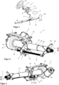
- Figure 1 shows a schematic steer-by-wire steering system 1 for a motor vehicle, with a steering column 2, which can be mounted on the body of the motor vehicle, not shown.
- a steering spindle 3 is mounted in the steering column 2 so that it can rotate about its longitudinal axis L.
- a steering wheel 31 is attached to the rear end of the steering spindle 3 facing the driver in relation to the direction of travel.
- a control unit 4 is connected via electrical control lines to a rotation angle sensor 41, which is inserted by the driver by turning the steering wheel 31 Steering command detects a rotation angle of the steering spindle 3. Depending on the measured angle of rotation and possibly other parameters such as the vehicle speed, the yaw rate and the like, the control unit 4 generates an electrical control signal and thus controls an electromotive steering actuator 5 via electrical control lines.
- the steering actuator 5 effects a steering angle of the steered wheels 53 via a steering gear 51 and tie rods 52 connected to it.
- the steering column 2 has an electrical feedback actuator 6 coupled to the steering shaft 3, from which, depending on the respective driving situation, a feedback torque can be coupled into the steering spindle 3, which simulates and records the effects of the road on the wheels 53 the steering wheel 31 transmits to give the driver feedback about the steering and driving behavior of the vehicle.
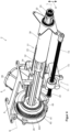
- the steering column 2 is in a first version in the Figures 2 to 9 shown.
- the steering spindle 3 is rotatably mounted about the longitudinal axis L in a casing unit 21, which has an outer casing tube 22, in which an intermediate casing tube 23 is accommodated coaxially and is arranged to be telescopically displaceable in the direction of the longitudinal axis L, in which in turn an inner casing tube 24 is also coaxial and in the direction the longitudinal axis L is arranged to be telescopically displaceable.
- the inner casing tube 24 has an outer diameter M; in the case of a non-round cross section, this is the diameter of the enveloping circle. This creates a triple telescopic arrangement of the casing unit 21.
- the steering spindle 3 has an outer shaft 32, on the rear end region of which, on the driver's side, protruding from the inner casing tube 24, a fastening section 33 is formed for the rotationally fixed attachment of the steering wheel 31.
- An inner shaft 34 telescopes coaxially into the outer shaft 32 designed as a hollow shaft in the direction of the longitudinal axis L adjustable, so that a double telescopic arrangement is formed.
- the inner shaft 34 and the outer shaft 32 are connected to one another in a torque-locking manner to transmit the steering torque, for example through corresponding non-round cross-sectional profiles, such as polygonal profiles known from length-adjustable shafts or groove-tooth profiles extending in the longitudinal direction or the like.
- the outer shaft 32 has an outer diameter A; in the case of a non-round cross section, this is the diameter of the enveloping circle.
- the inner shaft 34 extends into the front end region of the jacket unit 21.
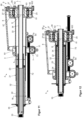
- the longitudinal section in Figure 6 shows the steering column 2 in the extended state, in which the intermediate casing tube 23 to the rear, in Figure 6 to the left, from the outer casing tube 22 in The longitudinal direction is pushed out, and the inner casing tube 24 is pushed out of the intermediate casing tube 23.
- the outer shaft 32 is rotatably mounted in steering spindle bearings 35, which are preferably designed as roller bearings, in the inner casing tube 24 about the longitudinal axis L, and is held immovably in the inner casing tube 24 in the longitudinal direction, ie in the direction of the longitudinal axis L, so that it is together during a longitudinal adjustment is moved with this.
- the inner shaft 34 is mounted in the outer casing tube 22 so that it cannot be displaced in the longitudinal direction.
- Figure 7 shows in the same longitudinal section view the collapsed state of the steering column 2, in which the intermediate casing tube 23 moves forward, in Figure 7 to the right, is inserted into the outer jacket tube 22, and the inner jacket tube 24 is inserted into the intermediate jacket tube 23.
- the feedback actuator 6 is attached to the outer jacket tube 22 on the jacket unit 21 in the front area and includes a drive unit 61.
- the drive unit 61 has a bell-shaped housing 25, which is attached to the outer jacket tube 22 in a cup-like manner at the front, and preferably in one piece the outer casing tube 22 is shaped, for example as a sheet metal or metal casting, or can also be made of plastic material.
- a bearing cover 26 is flanged to the front of the opening of the housing 25, which has a larger diameter than the outer casing tube 22.
- the drive unit 61 has a drive wheel 62, which is rotatably mounted coaxially to the longitudinal axis L in bearings 27 in the housing 25.
- the diameters of the drive wheel 62 and also the bearings 27 can be larger than the diameter of the outer casing tube 22, whereby a particularly rigid bearing arrangement can be realized.
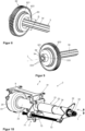
- the drive wheel 62 has a hub 621 with externally circumferential teeth 622.
- the toothing 622 is designed as a worm toothing and can be molded onto the hub 621, which is preferably made of steel, as a plastic encapsulation.
- the hub 621 and the inner shaft 34 are coupled to one another in a torque-locking manner, the inner shaft 34 being secured in the hub 621 in the direction of the longitudinal axis L by a caulking 333, which is designed as a local plastic deformation.
- the hub 621 is immovable relative to the inner shaft 34.
- the drive wheel 62 has a coaxial, in the example cylindrical, recess 63, which is opened axially towards the outer shaft 32 in relation to the steering spindle 3, as in the Figures 6, 7 and 8th is recognizable.
- the inner shaft 34 extends axially through the recess 63 and is connected in a torque-locking manner to the front end region of the inner shaft 34 in a connecting section 64. Through the connecting section 64, the annular space remaining free between the inner shaft 34 and the inner wall of the recess 63 is closed towards the front, so that a hollow cylindrical blind opening is formed.
- the recess has an inner diameter D that is larger than the outer diameter A of the outer shaft 32. This allows the outer shaft 32 to be in the collapsed state, as shown in Figure 7 shown, plunge forward axially into the drive wheel 62 of the drive unit 61. Because the outer diameter M of the inner casing tube 24 is larger than the inner diameter D, the inner casing tube 24 cannot dip into the recess 24, as shown in Figure 7 is recognizable.
- the feedback actuator 6 has a motor 65, namely an electric motor, to the motor shaft of which a worm 651 is coupled. From the cross-sectional view in Figure 5 It can be seen how the worm 651 meshes with the corresponding teeth 622 of the drive wheel 62.
- a second embodiment of a steering column 2 according to the invention is shown.
- this has a drive wheel 62 with a hub 621, which, however, has no teeth, but rather on which the rotor 66 of a motor 67 is arranged in a rotationally fixed manner, the stator 68 of which is mounted coaxially in a rotationally fixed manner in the housing 25.
- the bell-shaped housing 25 forms the motor housing.
- the drive wheel 62 directly has the rotor 66, so it essentially forms the motor shaft, so that a direct drive is realized without additional gear members.
- the drive unit 61 is thus integrated in a compact structural unit in the housing 25.
- the recess 63 and the advantages associated with it are as in the first embodiment variant.
- an adjusting drive 7 is provided, which is designed as a spindle drive, with a spindle nut 71 into which a threaded spindle 72 is screwed.
- the spindle nut 71 can be driven to rotate relative to the threaded spindle 72 by a servomotor 73. Because the spindle nut 71 is supported in the direction of the longitudinal axis L on the outer jacket tube 22, and the threaded spindle 72 on the inner jacket tube 24 - or vice versa - the jacket unit 21 can be moved together or apart by motor depending on the direction of rotation of the servomotor 73.
- the steering column 2 has a support unit 8, from which the jacket unit 21 is held.
- the casing unit 21 is mounted on the support unit 8 so that it can pivot about a pivot axis S lying horizontally transversely to the longitudinal axis L.
- the pivot axis S can preferably be arranged in the area of the housing 25 in the front area of the support unit 8.
- the jacket unit 21 is articulated to the support unit 8 via a movable pivot lever 81.
- the steering wheel 31 attached to the rear end can be moved up and down about the pivot axis S in the height direction H.
- an adjusting drive 9 which is designed as a spindle drive, with a spindle nut 91 into which a threaded spindle 92 is screwed and which can be driven in rotation relative to the spindle nut 91 by a servomotor 93.
- the threaded spindle 92 is supported in the direction of its axis on the support unit 21, and the spindle nut 91 is fixedly attached to the pivot lever 81 with respect to the rotation of the threaded spindle 92 and is supported in the direction of the axis of the threaded spindle 92.
Landscapes
- Engineering & Computer Science (AREA)
- Chemical & Material Sciences (AREA)
- Combustion & Propulsion (AREA)
- Transportation (AREA)
- Mechanical Engineering (AREA)
- Steering Controls (AREA)
- Power Steering Mechanism (AREA)
Claims (14)
- Colonne de direction (2) pour un système de direction Steer-by-Wire pour un véhicule automobile, comprenant une unité d'enveloppe (21) dans laquelle un arbre de direction (3) est logé de manière à pouvoir tourner autour d'un axe longitudinal (L), l'unité d'enveloppe (21) présentant un tube d'enveloppe intérieur (24) logé coaxialement dans un tube d'enveloppe extérieur (22) de manière à pouvoir coulisser de façon télescopique dans la direction de l'axe longitudinal (L), et l'arbre de direction (3) présentant un tube d'enveloppe extérieur (24) logé coaxialement dans un arbre extérieur (32) de manière à être solidaire en rotation, l'arbre de direction (3) pouvant être relié à un volant de direction (31) et étant couplé à une unité d'entraînement (61) d'un actionneur à rétroaction (6), qui présente un moteur électrique (65, 67) pour générer et introduire un couple de rétroaction dans l'arbre de direction (3),
l'unité d'entraînement (61) présentant un évidement (63) disposé coaxialement à l'axe longitudinal (63) et ouvert vers l'arbre extérieur (32), lequel évidement a un diamètre intérieur (D) inscrit maximal qui est supérieur au diamètre extérieur (A) de l'arbre extérieur (32), caractérisé en ce que le diamètre intérieur (D) est inférieur au diamètre extérieur (M) du tube d'enveloppe intérieur (24). - Colonne de direction selon la revendication 1, caractérisée en ce que la longueur du tube d'enveloppe intérieure (24) ou du tube d'enveloppe extérieure (22) est inférieure à la longueur de l'arbre extérieur (32).
- Colonne de direction selon l'une des revendications précédentes, caractérisée en ce qu'au moins un tube d'enveloppe intermédiaire (23) est disposé de manière réglable de façon télescopique entre le tube d'enveloppe intérieur (24) et le tube d'enveloppe extérieur (22).
- Colonne de direction selon l'une des revendications précédentes, caractérisée en ce que l'unité d'entraînement (61) présente une roue d'entraînement (62) entourant au moins partiellement de manière coaxiale l'évidement (63), qui peut être couplée à l'arbre de direction (3), et qui peut être entraînée en rotation par le moteur électrique (65, 67).
- Colonne de direction selon la revendication 4, caractérisée en ce que la roue motrice (62) est reliée à l'arbre intérieur (34).
- Colonne de direction selon l'une des revendications 4 à 5 précédentes, caractérisée en ce que la roue motrice (62) est une roue de transmission reliée au moteur électrique (65) par un engrenage.
- Colonne de direction selon l'une quelconque des revendications 4 à 5 précédentes, caractérisée en ce que la roue motrice (62) est formée d'un seul tenant avec un rotor (66) du moteur électrique (67).
- Colonne de direction selon l'une des revendications précédentes, caractérisée en ce que l'arbre de direction (3) est relié à l'unité d'entraînement (61) dans sa zone d'extrémité avant qui s'enfonce axialement dans l'évidement (63).
- Colonne de direction selon l'une des revendications précédentes, caractérisée en ce que l'unité d'entraînement (61) est montée sur un tube d'enveloppe extérieure (22).
- Colonne de direction selon l'une des revendications précédentes, caractérisée en ce que l'unité d'enveloppe (21) comprend un boîtier en forme de cloche (25) de l'unité d'entraînement (61).
- Colonne de direction selon l'une des revendications précédentes, caractérisée en ce qu'entre le tube d'enveloppe intérieure (24) et le tube d'enveloppe extérieure (22) s'engage un entraînement de réglage motorisé (7) qui est agencé pour se déplacer relativement dans la direction de l'axe longitudinal (L).
- Colonne de direction selon l'une des revendications précédentes, caractérisée en ce qu'un dispositif de serrage coopère avec l'unité d'enveloppe (21) et peut être amené dans une position de fixation, dans laquelle il immobilise le tube d'enveloppe intérieure (24) par rapport au tube d'enveloppe extérieure (22), et dans une position de libération, dans laquelle il libère un déplacement du tube d'enveloppe intérieure (24) par rapport au tube d'enveloppe extérieure (22).
- Colonne de direction selon l'une des revendications précédentes, caractérisée en ce que l'unité d'enveloppe (21) est maintenue dans une unité de support (8) pouvant être reliée à la carrosserie d'un véhicule automobile.
- Colonne de direction selon l'une des revendications précédentes, caractérisée en ce qu'un dispositif d'absorption d'énergie est monté entre les tubes d'enveloppe (22, 23, 24) et/ou entre l'un des tubes d'enveloppe (22, 23, 24) et une unité de support (8) maintenant les tubes d'enveloppe (22, 23, 24).
Applications Claiming Priority (2)
| Application Number | Priority Date | Filing Date | Title |
|---|---|---|---|
| DE102019200908.5A DE102019200908A1 (de) | 2019-01-24 | 2019-01-24 | Lenksäule für ein Steer-by-Wire-Lenksystem für ein Kraftfahrzeug |
| PCT/EP2020/051448 WO2020152188A1 (fr) | 2019-01-24 | 2020-01-22 | Colonne de direction pour système de direction à commande électrique pour un véhicule à moteur |
Publications (2)
| Publication Number | Publication Date |
|---|---|
| EP3914500A1 EP3914500A1 (fr) | 2021-12-01 |
| EP3914500B1 true EP3914500B1 (fr) | 2023-10-18 |
Family
ID=69713991
Family Applications (1)
| Application Number | Title | Priority Date | Filing Date |
|---|---|---|---|
| EP20707353.7A Active EP3914500B1 (fr) | 2019-01-24 | 2020-01-22 | Colonne de direction pour système de direction à commande électrique pour un véhicule à moteur |
Country Status (5)
| Country | Link |
|---|---|
| US (1) | US12275461B2 (fr) |
| EP (1) | EP3914500B1 (fr) |
| CN (1) | CN113329930B (fr) |
| DE (1) | DE102019200908A1 (fr) |
| WO (1) | WO2020152188A1 (fr) |
Families Citing this family (13)
| Publication number | Priority date | Publication date | Assignee | Title |
|---|---|---|---|---|
| DE102018101528B4 (de) * | 2018-01-24 | 2019-12-12 | Thyssenkrupp Ag | Lenksäule für ein Kraftfahrzeug |
| DE102018219264A1 (de) * | 2018-11-12 | 2020-05-14 | Thyssenkrupp Ag | Verstellantrieb für eine Lenksäule und Lenksäule für ein Kraftfahrzeug |
| JP7213743B2 (ja) * | 2019-04-23 | 2023-01-27 | 株式会社アイシン | ステアリング装置 |
| KR20210069995A (ko) * | 2019-12-04 | 2021-06-14 | 현대자동차주식회사 | 조향휠 수납장치 및 그 제어방법 |
| US11541862B2 (en) | 2020-08-27 | 2023-01-03 | Deere & Company | Operator selectable steering mode with variable torque feedback and system thereof |
| EP3960585B1 (fr) * | 2020-08-28 | 2023-09-27 | Lotus Tech Innovation Centre GmbH | Système de direction par câbles comprenant un dispositif de limitation de rotation de volant de direction |
| DE102020215759A1 (de) * | 2020-12-11 | 2022-06-15 | Thyssenkrupp Ag | Lenksäule mit kontrollierbarer Verstellbarkeit sowie Verfahren zum Betreiben einer solchen Lenksäule |
| US12263896B2 (en) | 2021-12-16 | 2025-04-01 | Deere & Company | Multi-selectable application mode steering system and method thereof |
| US12344251B2 (en) | 2021-12-16 | 2025-07-01 | Deere & Company | Multi-selectable application mode steering system and method thereof |
| US11713067B1 (en) * | 2022-01-26 | 2023-08-01 | Steering Solutions Ip Holding Corporation | Axially adjustable telescoping steering shaft assembly |
| BE1030038B1 (de) * | 2022-08-11 | 2023-07-11 | Thyssenkrupp Presta Ag | Steer-by-Wire-Lenksäule für ein Kraftfahrzeug |
| US11999407B1 (en) | 2023-02-21 | 2024-06-04 | Ford Global Technologies, Llc | Translating steering column with reduced packaging space |
| US20250276731A1 (en) * | 2024-03-01 | 2025-09-04 | Ferrari S.P.A. | Steering system for motor vehicle and motor vehicle comprising the same |
Family Cites Families (14)
| Publication number | Priority date | Publication date | Assignee | Title |
|---|---|---|---|---|
| DE19902557A1 (de) | 1999-01-22 | 2000-07-27 | Mercedes Benz Lenkungen Gmbh | Redundante Vorrichtung zur Erzeugung von Drehmomenten |
| DE10033810B4 (de) * | 2000-07-12 | 2005-10-27 | Daimlerchrysler Ag | Lenksäule eines Kraftfahrzeuges |
| KR20100031947A (ko) * | 2008-09-16 | 2010-03-25 | 현대모비스 주식회사 | 차량용 스티어링 컬럼 |
| DE112009002485A5 (de) * | 2008-12-19 | 2012-07-05 | C. Rob. Hammerstein Gmbh & Co. Kg | Längenverstellbare Lenkbetätigungseinheit für ein Kraftfahrzeug mit einem Träger und mit einer Lenksäule |
| DE102009017054A1 (de) * | 2009-04-01 | 2010-10-07 | Leopold Kostal Gmbh & Co. Kg | Lenksäule für Kraftfahrzeuge |
| DE102011050683A1 (de) * | 2011-05-27 | 2012-11-29 | Thyssenkrupp Presta Aktiengesellschaft | Lenksäule für ein Kraftfahrzeug |
| DE102015007280A1 (de) | 2015-06-10 | 2016-12-15 | Thyssenkrupp Ag | Fahrzeuglenkung mit Steer-by-Wire-System und mechanischer Rückfallebene |
| DE102015213303A1 (de) | 2015-07-15 | 2017-01-19 | Thyssenkrupp Ag | Feedback-Aktuator für eine Lenkeinrichtung |
| DE102015216326B4 (de) * | 2015-08-26 | 2016-09-08 | Thyssenkrupp Ag | Motorisch verstellbare Lenksäule für ein Kraftfahrzeug |
| DE102015224602B4 (de) * | 2015-12-08 | 2023-05-04 | Thyssenkrupp Ag | Lenksäule für eine steer-by-wire-Lenkeinrichtung |
| JP2017124715A (ja) * | 2016-01-13 | 2017-07-20 | 株式会社ショーワ | 操舵装置 |
| CN107521547B (zh) * | 2016-06-21 | 2020-03-10 | 操纵技术Ip控股公司 | 转向柱组件的自锁伸缩式致动器 |
| US10556614B2 (en) | 2017-07-11 | 2020-02-11 | Nio Usa, Inc. | Body mounted sliding steering column with offset feedback actuator |
| DE102018101528B4 (de) * | 2018-01-24 | 2019-12-12 | Thyssenkrupp Ag | Lenksäule für ein Kraftfahrzeug |
-
2019
- 2019-01-24 DE DE102019200908.5A patent/DE102019200908A1/de not_active Withdrawn
-
2020
- 2020-01-22 EP EP20707353.7A patent/EP3914500B1/fr active Active
- 2020-01-22 US US17/417,165 patent/US12275461B2/en active Active
- 2020-01-22 CN CN202080010458.9A patent/CN113329930B/zh active Active
- 2020-01-22 WO PCT/EP2020/051448 patent/WO2020152188A1/fr not_active Ceased
Also Published As
| Publication number | Publication date |
|---|---|
| US20220073127A1 (en) | 2022-03-10 |
| DE102019200908A1 (de) | 2020-07-30 |
| WO2020152188A1 (fr) | 2020-07-30 |
| CN113329930A (zh) | 2021-08-31 |
| CN113329930B (zh) | 2023-07-28 |
| US12275461B2 (en) | 2025-04-15 |
| EP3914500A1 (fr) | 2021-12-01 |
Similar Documents
| Publication | Publication Date | Title |
|---|---|---|
| EP3914500B1 (fr) | Colonne de direction pour système de direction à commande électrique pour un véhicule à moteur | |
| EP3743324B1 (fr) | Colonne de direction pour un véhicule automobile | |
| EP3322632B1 (fr) | Actionneur à rétroaction pour un dispositif de direction | |
| DE102015224602B4 (de) | Lenksäule für eine steer-by-wire-Lenkeinrichtung | |
| DE102018212696B3 (de) | Verstellantrieb für eine Lenksäule und Lenksäule für ein Kraftfahrzeug | |
| EP3500476B1 (fr) | Manche permettant de diriger un véhicule automobile | |
| EP4054918B1 (fr) | Actionneur à rétroaction pour un système de direction d'un véhicule à moteur | |
| EP4103451B1 (fr) | Colonne de direction pour un véhicule à moteur | |
| EP4175865B1 (fr) | Colonne de direction pour véhicule automobile | |
| DE10033810A1 (de) | Lenksäule eines Kraftfahrzeuges | |
| WO2019121331A1 (fr) | Colonne de direction à réglage motorisé pour véhicule à moteur | |
| EP3538420B1 (fr) | Direction à crémaillère pour véhicule à moteur dotée d'un engrenage à vis sans fin | |
| DE102018127099A1 (de) | Lenksäule mit Verriegelungsvorrichtung | |
| WO2018087112A1 (fr) | Procédé pour simplifier le montage d'un mécanisme de direction à crémaillère | |
| DE102018127098B3 (de) | Lenkwelle für eine Lenksäule eines Kraftfahrzeugs und Lenksäule für ein Kraftfahrzeug | |
| EP4245643B1 (fr) | Colonne de direction pour un véhicule automobile | |
| BE1030038B1 (de) | Steer-by-Wire-Lenksäule für ein Kraftfahrzeug | |
| EP4279357A1 (fr) | Système de direction pour un véhicule automobile | |
| DE10249718A1 (de) | Lenkvorrichtung für Kraftfahrzeuge | |
| EP4321412B1 (fr) | Entraînement de réglage pour une colonne de direction réglable par moteur et colonne de direction pour un véhicule automobile | |
| EP1843931A1 (fr) | Direction dotee d'un systeme sac gonflable et son mode de fonctionnement |
Legal Events
| Date | Code | Title | Description |
|---|---|---|---|
| STAA | Information on the status of an ep patent application or granted ep patent |
Free format text: STATUS: UNKNOWN |
|
| STAA | Information on the status of an ep patent application or granted ep patent |
Free format text: STATUS: THE INTERNATIONAL PUBLICATION HAS BEEN MADE |
|
| PUAI | Public reference made under article 153(3) epc to a published international application that has entered the european phase |
Free format text: ORIGINAL CODE: 0009012 |
|
| STAA | Information on the status of an ep patent application or granted ep patent |
Free format text: STATUS: REQUEST FOR EXAMINATION WAS MADE |
|
| 17P | Request for examination filed |
Effective date: 20210824 |
|
| AK | Designated contracting states |
Kind code of ref document: A1 Designated state(s): AL AT BE BG CH CY CZ DE DK EE ES FI FR GB GR HR HU IE IS IT LI LT LU LV MC MK MT NL NO PL PT RO RS SE SI SK SM TR |
|
| DAV | Request for validation of the european patent (deleted) | ||
| DAX | Request for extension of the european patent (deleted) | ||
| GRAP | Despatch of communication of intention to grant a patent |
Free format text: ORIGINAL CODE: EPIDOSNIGR1 |
|
| STAA | Information on the status of an ep patent application or granted ep patent |
Free format text: STATUS: GRANT OF PATENT IS INTENDED |
|
| INTG | Intention to grant announced |
Effective date: 20230525 |
|
| GRAS | Grant fee paid |
Free format text: ORIGINAL CODE: EPIDOSNIGR3 |
|
| GRAA | (expected) grant |
Free format text: ORIGINAL CODE: 0009210 |
|
| STAA | Information on the status of an ep patent application or granted ep patent |
Free format text: STATUS: THE PATENT HAS BEEN GRANTED |
|
| AK | Designated contracting states |
Kind code of ref document: B1 Designated state(s): AL AT BE BG CH CY CZ DE DK EE ES FI FR GB GR HR HU IE IS IT LI LT LU LV MC MK MT NL NO PL PT RO RS SE SI SK SM TR |
|
| REG | Reference to a national code |
Ref country code: GB Ref legal event code: FG4D Free format text: NOT ENGLISH |
|
| REG | Reference to a national code |
Ref country code: CH Ref legal event code: EP |
|
| REG | Reference to a national code |
Ref country code: DE Ref legal event code: R096 Ref document number: 502020005695 Country of ref document: DE |
|
| REG | Reference to a national code |
Ref country code: IE Ref legal event code: FG4D Free format text: LANGUAGE OF EP DOCUMENT: GERMAN |
|
| REG | Reference to a national code |
Ref country code: DE Ref legal event code: R084 Ref document number: 502020005695 Country of ref document: DE |
|
| REG | Reference to a national code |
Ref country code: LT Ref legal event code: MG9D |
|
| REG | Reference to a national code |
Ref country code: NL Ref legal event code: MP Effective date: 20231018 |
|
| PG25 | Lapsed in a contracting state [announced via postgrant information from national office to epo] |
Ref country code: NL Free format text: LAPSE BECAUSE OF FAILURE TO SUBMIT A TRANSLATION OF THE DESCRIPTION OR TO PAY THE FEE WITHIN THE PRESCRIBED TIME-LIMIT Effective date: 20231018 |
|
| PG25 | Lapsed in a contracting state [announced via postgrant information from national office to epo] |
Ref country code: GR Free format text: LAPSE BECAUSE OF FAILURE TO SUBMIT A TRANSLATION OF THE DESCRIPTION OR TO PAY THE FEE WITHIN THE PRESCRIBED TIME-LIMIT Effective date: 20240119 |
|
| PG25 | Lapsed in a contracting state [announced via postgrant information from national office to epo] |
Ref country code: IS Free format text: LAPSE BECAUSE OF FAILURE TO SUBMIT A TRANSLATION OF THE DESCRIPTION OR TO PAY THE FEE WITHIN THE PRESCRIBED TIME-LIMIT Effective date: 20240218 |
|
| PG25 | Lapsed in a contracting state [announced via postgrant information from national office to epo] |
Ref country code: LT Free format text: LAPSE BECAUSE OF FAILURE TO SUBMIT A TRANSLATION OF THE DESCRIPTION OR TO PAY THE FEE WITHIN THE PRESCRIBED TIME-LIMIT Effective date: 20231018 |
|
| PG25 | Lapsed in a contracting state [announced via postgrant information from national office to epo] |
Ref country code: ES Free format text: LAPSE BECAUSE OF FAILURE TO SUBMIT A TRANSLATION OF THE DESCRIPTION OR TO PAY THE FEE WITHIN THE PRESCRIBED TIME-LIMIT Effective date: 20231018 |
|
| PG25 | Lapsed in a contracting state [announced via postgrant information from national office to epo] |
Ref country code: LT Free format text: LAPSE BECAUSE OF FAILURE TO SUBMIT A TRANSLATION OF THE DESCRIPTION OR TO PAY THE FEE WITHIN THE PRESCRIBED TIME-LIMIT Effective date: 20231018 Ref country code: IS Free format text: LAPSE BECAUSE OF FAILURE TO SUBMIT A TRANSLATION OF THE DESCRIPTION OR TO PAY THE FEE WITHIN THE PRESCRIBED TIME-LIMIT Effective date: 20240218 Ref country code: GR Free format text: LAPSE BECAUSE OF FAILURE TO SUBMIT A TRANSLATION OF THE DESCRIPTION OR TO PAY THE FEE WITHIN THE PRESCRIBED TIME-LIMIT Effective date: 20240119 Ref country code: ES Free format text: LAPSE BECAUSE OF FAILURE TO SUBMIT A TRANSLATION OF THE DESCRIPTION OR TO PAY THE FEE WITHIN THE PRESCRIBED TIME-LIMIT Effective date: 20231018 Ref country code: BG Free format text: LAPSE BECAUSE OF FAILURE TO SUBMIT A TRANSLATION OF THE DESCRIPTION OR TO PAY THE FEE WITHIN THE PRESCRIBED TIME-LIMIT Effective date: 20240118 Ref country code: PT Free format text: LAPSE BECAUSE OF FAILURE TO SUBMIT A TRANSLATION OF THE DESCRIPTION OR TO PAY THE FEE WITHIN THE PRESCRIBED TIME-LIMIT Effective date: 20240219 |
|
| PG25 | Lapsed in a contracting state [announced via postgrant information from national office to epo] |
Ref country code: SE Free format text: LAPSE BECAUSE OF FAILURE TO SUBMIT A TRANSLATION OF THE DESCRIPTION OR TO PAY THE FEE WITHIN THE PRESCRIBED TIME-LIMIT Effective date: 20231018 Ref country code: RS Free format text: LAPSE BECAUSE OF FAILURE TO SUBMIT A TRANSLATION OF THE DESCRIPTION OR TO PAY THE FEE WITHIN THE PRESCRIBED TIME-LIMIT Effective date: 20231018 Ref country code: PL Free format text: LAPSE BECAUSE OF FAILURE TO SUBMIT A TRANSLATION OF THE DESCRIPTION OR TO PAY THE FEE WITHIN THE PRESCRIBED TIME-LIMIT Effective date: 20231018 Ref country code: NO Free format text: LAPSE BECAUSE OF FAILURE TO SUBMIT A TRANSLATION OF THE DESCRIPTION OR TO PAY THE FEE WITHIN THE PRESCRIBED TIME-LIMIT Effective date: 20240118 Ref country code: LV Free format text: LAPSE BECAUSE OF FAILURE TO SUBMIT A TRANSLATION OF THE DESCRIPTION OR TO PAY THE FEE WITHIN THE PRESCRIBED TIME-LIMIT Effective date: 20231018 Ref country code: HR Free format text: LAPSE BECAUSE OF FAILURE TO SUBMIT A TRANSLATION OF THE DESCRIPTION OR TO PAY THE FEE WITHIN THE PRESCRIBED TIME-LIMIT Effective date: 20231018 |
|
| PG25 | Lapsed in a contracting state [announced via postgrant information from national office to epo] |
Ref country code: DK Free format text: LAPSE BECAUSE OF FAILURE TO SUBMIT A TRANSLATION OF THE DESCRIPTION OR TO PAY THE FEE WITHIN THE PRESCRIBED TIME-LIMIT Effective date: 20231018 |
|
| REG | Reference to a national code |
Ref country code: DE Ref legal event code: R097 Ref document number: 502020005695 Country of ref document: DE |
|
| PG25 | Lapsed in a contracting state [announced via postgrant information from national office to epo] |
Ref country code: CZ Free format text: LAPSE BECAUSE OF FAILURE TO SUBMIT A TRANSLATION OF THE DESCRIPTION OR TO PAY THE FEE WITHIN THE PRESCRIBED TIME-LIMIT Effective date: 20231018 |
|
| PG25 | Lapsed in a contracting state [announced via postgrant information from national office to epo] |
Ref country code: SK Free format text: LAPSE BECAUSE OF FAILURE TO SUBMIT A TRANSLATION OF THE DESCRIPTION OR TO PAY THE FEE WITHIN THE PRESCRIBED TIME-LIMIT Effective date: 20231018 |
|
| PG25 | Lapsed in a contracting state [announced via postgrant information from national office to epo] |
Ref country code: SM Free format text: LAPSE BECAUSE OF FAILURE TO SUBMIT A TRANSLATION OF THE DESCRIPTION OR TO PAY THE FEE WITHIN THE PRESCRIBED TIME-LIMIT Effective date: 20231018 Ref country code: SK Free format text: LAPSE BECAUSE OF FAILURE TO SUBMIT A TRANSLATION OF THE DESCRIPTION OR TO PAY THE FEE WITHIN THE PRESCRIBED TIME-LIMIT Effective date: 20231018 Ref country code: RO Free format text: LAPSE BECAUSE OF FAILURE TO SUBMIT A TRANSLATION OF THE DESCRIPTION OR TO PAY THE FEE WITHIN THE PRESCRIBED TIME-LIMIT Effective date: 20231018 Ref country code: IT Free format text: LAPSE BECAUSE OF FAILURE TO SUBMIT A TRANSLATION OF THE DESCRIPTION OR TO PAY THE FEE WITHIN THE PRESCRIBED TIME-LIMIT Effective date: 20231018 Ref country code: EE Free format text: LAPSE BECAUSE OF FAILURE TO SUBMIT A TRANSLATION OF THE DESCRIPTION OR TO PAY THE FEE WITHIN THE PRESCRIBED TIME-LIMIT Effective date: 20231018 Ref country code: DK Free format text: LAPSE BECAUSE OF FAILURE TO SUBMIT A TRANSLATION OF THE DESCRIPTION OR TO PAY THE FEE WITHIN THE PRESCRIBED TIME-LIMIT Effective date: 20231018 Ref country code: CZ Free format text: LAPSE BECAUSE OF FAILURE TO SUBMIT A TRANSLATION OF THE DESCRIPTION OR TO PAY THE FEE WITHIN THE PRESCRIBED TIME-LIMIT Effective date: 20231018 |
|
| PLBE | No opposition filed within time limit |
Free format text: ORIGINAL CODE: 0009261 |
|
| STAA | Information on the status of an ep patent application or granted ep patent |
Free format text: STATUS: NO OPPOSITION FILED WITHIN TIME LIMIT |
|
| PG25 | Lapsed in a contracting state [announced via postgrant information from national office to epo] |
Ref country code: MC Free format text: LAPSE BECAUSE OF FAILURE TO SUBMIT A TRANSLATION OF THE DESCRIPTION OR TO PAY THE FEE WITHIN THE PRESCRIBED TIME-LIMIT Effective date: 20231018 |
|
| PG25 | Lapsed in a contracting state [announced via postgrant information from national office to epo] |
Ref country code: MC Free format text: LAPSE BECAUSE OF FAILURE TO SUBMIT A TRANSLATION OF THE DESCRIPTION OR TO PAY THE FEE WITHIN THE PRESCRIBED TIME-LIMIT Effective date: 20231018 |
|
| REG | Reference to a national code |
Ref country code: CH Ref legal event code: PL |
|
| PG25 | Lapsed in a contracting state [announced via postgrant information from national office to epo] |
Ref country code: LU Free format text: LAPSE BECAUSE OF NON-PAYMENT OF DUE FEES Effective date: 20240122 |
|
| 26N | No opposition filed |
Effective date: 20240719 |
|
| GBPC | Gb: european patent ceased through non-payment of renewal fee |
Effective date: 20240122 |
|
| PG25 | Lapsed in a contracting state [announced via postgrant information from national office to epo] |
Ref country code: LU Free format text: LAPSE BECAUSE OF NON-PAYMENT OF DUE FEES Effective date: 20240122 |
|
| PG25 | Lapsed in a contracting state [announced via postgrant information from national office to epo] |
Ref country code: GB Free format text: LAPSE BECAUSE OF NON-PAYMENT OF DUE FEES Effective date: 20240122 |
|
| PG25 | Lapsed in a contracting state [announced via postgrant information from national office to epo] |
Ref country code: BE Free format text: LAPSE BECAUSE OF NON-PAYMENT OF DUE FEES Effective date: 20240131 |
|
| PG25 | Lapsed in a contracting state [announced via postgrant information from national office to epo] |
Ref country code: FR Free format text: LAPSE BECAUSE OF NON-PAYMENT OF DUE FEES Effective date: 20240131 |
|
| PG25 | Lapsed in a contracting state [announced via postgrant information from national office to epo] |
Ref country code: CH Free format text: LAPSE BECAUSE OF NON-PAYMENT OF DUE FEES Effective date: 20240131 |
|
| PG25 | Lapsed in a contracting state [announced via postgrant information from national office to epo] |
Ref country code: SI Free format text: LAPSE BECAUSE OF FAILURE TO SUBMIT A TRANSLATION OF THE DESCRIPTION OR TO PAY THE FEE WITHIN THE PRESCRIBED TIME-LIMIT Effective date: 20231018 |
|
| PG25 | Lapsed in a contracting state [announced via postgrant information from national office to epo] |
Ref country code: SI Free format text: LAPSE BECAUSE OF FAILURE TO SUBMIT A TRANSLATION OF THE DESCRIPTION OR TO PAY THE FEE WITHIN THE PRESCRIBED TIME-LIMIT Effective date: 20231018 Ref country code: GB Free format text: LAPSE BECAUSE OF NON-PAYMENT OF DUE FEES Effective date: 20240122 Ref country code: FR Free format text: LAPSE BECAUSE OF NON-PAYMENT OF DUE FEES Effective date: 20240131 Ref country code: CH Free format text: LAPSE BECAUSE OF NON-PAYMENT OF DUE FEES Effective date: 20240131 Ref country code: BE Free format text: LAPSE BECAUSE OF NON-PAYMENT OF DUE FEES Effective date: 20240131 |
|
| REG | Reference to a national code |
Ref country code: BE Ref legal event code: MM Effective date: 20240131 |
|
| PG25 | Lapsed in a contracting state [announced via postgrant information from national office to epo] |
Ref country code: IE Free format text: LAPSE BECAUSE OF NON-PAYMENT OF DUE FEES Effective date: 20240122 |
|
| PG25 | Lapsed in a contracting state [announced via postgrant information from national office to epo] |
Ref country code: IE Free format text: LAPSE BECAUSE OF NON-PAYMENT OF DUE FEES Effective date: 20240122 |
|
| PGFP | Annual fee paid to national office [announced via postgrant information from national office to epo] |
Ref country code: AT Payment date: 20250417 Year of fee payment: 5 |
|
| PG25 | Lapsed in a contracting state [announced via postgrant information from national office to epo] |
Ref country code: CY Free format text: LAPSE BECAUSE OF FAILURE TO SUBMIT A TRANSLATION OF THE DESCRIPTION OR TO PAY THE FEE WITHIN THE PRESCRIBED TIME-LIMIT; INVALID AB INITIO Effective date: 20200122 |
|
| PG25 | Lapsed in a contracting state [announced via postgrant information from national office to epo] |
Ref country code: HU Free format text: LAPSE BECAUSE OF FAILURE TO SUBMIT A TRANSLATION OF THE DESCRIPTION OR TO PAY THE FEE WITHIN THE PRESCRIBED TIME-LIMIT; INVALID AB INITIO Effective date: 20200122 |
|
| PG25 | Lapsed in a contracting state [announced via postgrant information from national office to epo] |
Ref country code: FI Free format text: LAPSE BECAUSE OF FAILURE TO SUBMIT A TRANSLATION OF THE DESCRIPTION OR TO PAY THE FEE WITHIN THE PRESCRIBED TIME-LIMIT Effective date: 20231019 |
|
| PG25 | Lapsed in a contracting state [announced via postgrant information from national office to epo] |
Ref country code: TR Free format text: LAPSE BECAUSE OF FAILURE TO SUBMIT A TRANSLATION OF THE DESCRIPTION OR TO PAY THE FEE WITHIN THE PRESCRIBED TIME-LIMIT Effective date: 20231018 |
|
| REG | Reference to a national code |
Ref country code: AT Ref legal event code: MM01 Ref document number: 1622199 Country of ref document: AT Kind code of ref document: T Effective date: 20250122 |
|
| PGFP | Annual fee paid to national office [announced via postgrant information from national office to epo] |
Ref country code: DE Payment date: 20260121 Year of fee payment: 7 |
|
| PG25 | Lapsed in a contracting state [announced via postgrant information from national office to epo] |
Ref country code: AT Free format text: LAPSE BECAUSE OF NON-PAYMENT OF DUE FEES Effective date: 20250122 |