EP4054918B1 - Actionneur à rétroaction pour un système de direction d'un véhicule à moteur - Google Patents
Actionneur à rétroaction pour un système de direction d'un véhicule à moteur Download PDFInfo
- Publication number
- EP4054918B1 EP4054918B1 EP20829314.2A EP20829314A EP4054918B1 EP 4054918 B1 EP4054918 B1 EP 4054918B1 EP 20829314 A EP20829314 A EP 20829314A EP 4054918 B1 EP4054918 B1 EP 4054918B1
- Authority
- EP
- European Patent Office
- Prior art keywords
- casing
- outer casing
- feedback actuator
- unit
- gear
- Prior art date
- Legal status (The legal status is an assumption and is not a legal conclusion. Google has not performed a legal analysis and makes no representation as to the accuracy of the status listed.)
- Active
Links
Images


Classifications
-
- B—PERFORMING OPERATIONS; TRANSPORTING
- B62—LAND VEHICLES FOR TRAVELLING OTHERWISE THAN ON RAILS
- B62D—MOTOR VEHICLES; TRAILERS
- B62D5/00—Power-assisted or power-driven steering
- B62D5/001—Mechanical components or aspects of steer-by-wire systems, not otherwise provided for in this maingroup
- B62D5/005—Mechanical components or aspects of steer-by-wire systems, not otherwise provided for in this maingroup means for generating torque on steering wheel or input member, e.g. feedback
- B62D5/006—Mechanical components or aspects of steer-by-wire systems, not otherwise provided for in this maingroup means for generating torque on steering wheel or input member, e.g. feedback power actuated
-
- B—PERFORMING OPERATIONS; TRANSPORTING
- B62—LAND VEHICLES FOR TRAVELLING OTHERWISE THAN ON RAILS
- B62D—MOTOR VEHICLES; TRAILERS
- B62D1/00—Steering controls, i.e. means for initiating a change of direction of the vehicle
- B62D1/02—Steering controls, i.e. means for initiating a change of direction of the vehicle vehicle-mounted
- B62D1/16—Steering columns
- B62D1/18—Steering columns yieldable or adjustable, e.g. tiltable
- B62D1/181—Steering columns yieldable or adjustable, e.g. tiltable with power actuated adjustment, e.g. with position memory
-
- B—PERFORMING OPERATIONS; TRANSPORTING
- B62—LAND VEHICLES FOR TRAVELLING OTHERWISE THAN ON RAILS
- B62D—MOTOR VEHICLES; TRAILERS
- B62D1/00—Steering controls, i.e. means for initiating a change of direction of the vehicle
- B62D1/02—Steering controls, i.e. means for initiating a change of direction of the vehicle vehicle-mounted
- B62D1/16—Steering columns
- B62D1/18—Steering columns yieldable or adjustable, e.g. tiltable
- B62D1/185—Steering columns yieldable or adjustable, e.g. tiltable adjustable by axial displacement, e.g. telescopically
Definitions
- the invention relates to a feedback actuator for a steering device of a motor vehicle, comprising a casing unit which has an outer casing which can be attached to a motor vehicle and in which an inner casing is accommodated so as to be telescopically adjustable in the longitudinal direction, in which a steering spindle is mounted so as to be rotatable about a longitudinal axis, wherein an electric motor of a drive unit is arranged in an interior of the casing unit, which has a stator fixed to the casing unit and a rotatably drivable rotor with a rotor shaft which is coupled to the steering spindle via a gear, wherein the stator is fixed to the outer casing.
- Steer-by-wire steering systems for motor vehicles accept manual steering commands from the driver like conventional mechanical steering systems by turning a steering wheel of an input unit that is attached to the rear end of a steering spindle on the driver's side.
- the steering spindle is not mechanically connected to the wheels to be steered via the steering gear, but rather works together with angle of rotation or torque sensors that record the steering command and send an electrical control signal determined from it to a steering actuator, which sets the appropriate steering angle of the wheels using an electric actuator.
- the driver does not receive any direct physical feedback from the steered wheels via the steering line, which in conventional mechanically coupled steering systems is reported back to the steering wheel as a reaction or restoring torque depending on the road surface condition, the vehicle speed, the current steering angle and other operating conditions.
- the lack of haptic feedback makes it difficult for the driver to reliably grasp current driving situations and carry out appropriate steering maneuvers, which impairs the vehicle's steerability and thus driving safety.
- the feedback actuator is integrated into the input unit and has an actuator unit that includes a manual torque or steering wheel actuator with a drive unit that, depending on the feedback signal, couples a restoring torque (feedback torque) corresponding to the real reaction torque into the steering wheel via the steering spindle.
- Such "force feedback" systems give the driver the impression of a real driving situation as with conventional steering, which facilitates an intuitive reaction.
- a generic feedback actuator of the type mentioned at the beginning is known.
- This comprises a casing unit with an inner casing, also referred to as an inner casing tube or inner casing pipe, in which the steering spindle is mounted so as to be rotatable about the longitudinal axis, at the rear end of which, in relation to the direction of travel and facing the driver, the steering wheel is attached.
- the inner casing is accommodated in an outer casing, also referred to as an outer casing tube or guide box, so that it can be moved axially in a telescopic manner in the longitudinal direction, i.e. in the direction of the longitudinal axis.
- the inner casing can be retracted as far forward as possible into the outer casing in the direction of travel.
- the actuator's drive unit comprises an electric motor which is housed together with a gear unit in an advantageously compact, space-saving arrangement in the casing unit coaxially to the longitudinal axis.
- the stator is axially and rotationally fixed in the inner casing. Due to the known arrangement within the inner casing, the entire drive unit is moved axially together with the inner casing relative to the outer casing when adjusting and stowing. As a result, the entire inertial mass of the drive unit must be accelerated during longitudinal adjustment, so that a relatively high drive power is required for rapid retraction and extension.
- the electrical supply lines must be designed to be movable in order to be able to follow the relative movement of the inner casing during adjustment.
- the installation space available for the gear unit in the interior of the inner casing is very limited, so that the design of the gear unit is restricted or technically complex.
- a feedback actuator of the type mentioned above is known from DE 100 33 810 A1 known.
- a feedback actuator for a steering device of a motor vehicle comprising a casing unit which has an outer casing which can be attached to a motor vehicle and in which an inner casing is accommodated such that it can be adjusted telescopically in the longitudinal direction and in which a steering spindle is mounted so as to be rotatable about a longitudinal axis
- an electric motor of a drive unit is arranged in an interior of the casing unit, which has a stator fixed to the casing unit and a rotatably drivable rotor with a rotor shaft which is coupled to the steering spindle via a gear
- the stator is fixed to the outer casing
- the motor has an outer cross section which is smaller than an inner cross section of the inner casing.
- the rotor shaft is preferably aligned coaxially or axially parallel to the longitudinal axis.
- the motor is preferably arranged coaxially or axially parallel to the longitudinal axis in the outer casing and is fixed in the longitudinal direction, i.e. axially and rotationally fixed with respect to rotation around the longitudinal axis.
- the motor of the drive unit is mounted inside the outer casing.
- the gear unit connected to the motor shaft can be located inside the outer casing, but does not have to be. In particular, it is not necessary to accommodate the gear unit inside the narrow interior space inside the inner casing. It can be particularly advantageous if the gear unit is located at least partially outside the interior space of the outer casing. This makes it possible to provide a larger installation space that is not limited by the dimensions of the interior space of the outer or inner casing. Because no highly resilient, miniaturized structure is required, the design and manufacturing effort can be reduced.
- the motor has an external cross-section that is smaller than an internal cross-section of the inner casing.
- the external cross-section of the motor generally corresponds to the external cross-section of the stator. Because this is smaller than an axially open internal cross-section of the inner casing, which can preferably be designed as an inner casing tube, it is possible for the motor to be at least partially immersed in an interior of the inner casing in the retracted state in which the inner casing is completely or at least partially pushed into the outer casing. This allows the casing unit to be designed to be particularly compact.
- the stator can be fixed to an inner side that delimits the interior of the outer casing, for example a casing surface or axial end face.
- a detachable or non-detachable connection can be formed, which can be optimized with regard to low manufacturing and assembly costs.
- positive and/or material-locking connecting means can be used, for example screw, rivet, adhesive or welded connections, or also flanging, caulking or the like.
- the outer casing and/or the inner casing are tubular in shape at least in sections.
- a tubular shape is understood to mean all hollow profiles and is not limited to a circular cylindrical cross-section.
- an outer or inner casing pipe or a pipe section with a round or non-round cross-section for example a triangular, square, hexagonal, octagonal or polygonal cross-section, can be used as the outer or inner casing pipe.
- a further casing tube is arranged as an intermediate casing tube, which is adjustable relative to the outer casing and the inner casing.
- This arrangement is also referred to as a multiple telescope arrangement. Additional casing tubes can also be provided.
- a coaxial gap is formed between the motor and the outer casing, in which the inner casing can be accommodated.
- the gap is located between the stator of the motor and the inside of the outer casing, and extends at least in sections in the longitudinal direction over the motor.
- the gap offers an axial movement space into which the inner casing can be pushed in when adjusting in the longitudinal direction.
- the gap is designed like a ring.
- the motor can have an external cross-section that is smaller than an internal cross-section at the front end of the inner casing tube that is open at the front and that penetrates into the outer casing. Because the motor can penetrate axially from the front into the inner casing tube when the inner casing is pushed into the outer casing in the longitudinal direction, a short length can be achieved in the maximally pushed-together stowed position of the casing unit.
- the drive unit is coupled to the steering spindle via a shaft arrangement that is variable in length in the longitudinal direction.
- the torque generated by the drive unit is transmitted to the steering spindle via the shaft arrangement.
- the variable-length shaft arrangement can compensate for the axial distance between the outer and inner casing, which varies in different adjustment states of the casing unit and can be changed during adjustment, so that torque transmission is guaranteed in every longitudinal setting of the casing unit.
- Known variable-length shaft arrangements can be used, for example telescopic toothed shafts or non-circular shafts, in each of which an inner shaft with a non-circular cross-section engages in a torque-locking manner in a corresponding inner cross-section of a hollow or outer shaft in an axially displaceable manner.
- the steering spindle has a hollow shaft into which an inner shaft that can be driven in rotation by the drive unit engages, or vice versa.
- the part of the shaft arrangement that is axially movable relative to the outer casing is mounted in the inner casing as part of the steering spindle, which means that the entire mass of the inner casing that is moved during adjustment can advantageously be made relatively small. In any case, this moving mass is generally significantly smaller than if the drive unit is connected to the inner casing, as in the prior art.
- the motor is arranged in an end region of the outer casing facing away from the inner casing in the longitudinal direction.
- the stator is accordingly fixed in a front region of the outer casing in the direction of travel.
- This allows the drive unit to be mounted on the outer casing from the front end, preferably on an outer casing tube.
- the uncomplicated structure and easy assembly are advantageous.
- the gear is arranged at least partially outside the interior of the outer casing.
- the external dimensions of the gear for example the external cross section
- the gear can protrude outwards beyond the outer casing and can, for example, be housed in a gear housing attached to the outer casing.
- the gear can be attached to the front of the outer casing tube, preferably axially on the front end at the front end, for example in a gear housing, whereby the motor shaft can be coupled to a coaxial input shaft of the gear.
- gear can be easily adapted to the required transmission properties and the installation space available in the vehicle.
- one-, two- or multi-stage gears can be implemented, also in different gear, belt, planetary or other gear designs.
- continuously variable transmission Continuous Variable Transmission
- the rotor shaft is designed as a hollow shaft through which an output shaft of the transmission or the steering spindle is passed coaxially and coupled to the steering spindle.
- the rotor shaft which is coaxial to the longitudinal axis, can be connected to the input shaft of the transmission, for example, through an opening in the outer casing, for example a front axial opening on the front side of an outer casing tube.
- the transmission can, for example, be attached to the front end of the outer casing tube as in the previously described embodiment, with an input shaft being coupled to the rotor shaft.
- the input shaft acts on the output shaft via transmission-specific transmission elements such as intermediate gears, intermediate shafts or the like. together.
- the output shaft is also arranged coaxially to the longitudinal axis and is led axially inwards through the rotor shaft, which is designed as a hollow shaft, into the outer casing and connected to the steering spindle, or a shaft part of the steering spindle is led outwards through the rotor shaft from the outer casing and coupled to the output shaft.
- the coaxial arrangement of the rotor shaft and output shaft enables a particularly compact design to be achieved.
- An electrical control unit can be attached to the outer casing or to the gear housing. This can have electrical control and connection means for operating the motor. This advantageously allows a compact design to be created.
- the gear unit which can be designed with one or more stages, can have a transmission ratio (total transmission ratio) between 1:3 and 1:25, particularly preferably between 1:5 and 1:15. It can be designed, for example, as a single- or multi-stage spur gear, belt or other transmission. It can be advantageous for the gear unit to have a transmission housing which is detachably or permanently connected to the outer casing. This means that a gear unit can be easily provided and assembled as a transmission assembly. It is also conceivable and possible to provide different transmission assemblies with transmission properties adapted to different purposes, which can be mounted on a casing unit as required to implement different feedback characteristics.
- a motorized adjustment drive is arranged between the inner and outer casings.
- the adjustment drive preferably comprises a linear drive that is effective between the inner and outer casings. This allows a motorized longitudinal adjustment of the casing unit.
- the adjustment drive can have a rotary or plunger spindle drive that can be driven by an electric servomotor and that acts on the inner and outer casings.
- the casing unit can be held by a support unit that can be connected to a vehicle body.
- the support unit serves to hold the casing unit, specifically to fix the outer casing in the longitudinal direction relative to the vehicle body.
- the casing unit can be mounted in a height-adjustable manner relative to the support unit transversely to the longitudinal axis in order to be able to adjust the height of the steering wheel relative to the driver's position.
- the height adjustment can be achieved by pivoting the casing unit about a horizontal pivot axis in the support unit, either manually or by means of a motorized actuator similar to that described above for the longitudinal adjustment.
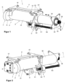
- Figures 1 and 2 show schematic perspective external views of a steering input device 1 for a motor vehicle (not shown) in the form of a length-adjustable steering column, which has a feedback actuator 2 according to the invention.
- Figure 1 shows a view obliquely from the rear left - related to the direction of travel - and Figure 2 diagonally from the front left, i.e. on the same side against the direction of travel.
- the feedback actuator 2 has a casing unit 3, with a substantially tubular outer casing 31, also referred to as outer casing tube or guide box, which is open to the rear, and in which a tubular inner casing 32, also referred to as inner casing tube or inner casing, is accommodated coaxially to a longitudinal axis L, which in can be moved longitudinally or axially in a telescopic manner in the direction of a central longitudinal axis L, as indicated by a double arrow.
- a casing unit 3 with a substantially tubular outer casing 31, also referred to as outer casing tube or guide box, which is open to the rear, and in which a tubular inner casing 32, also referred to as inner casing tube or inner casing, is accommodated coaxially to a longitudinal axis L, which in can be moved longitudinally or axially in a telescopic manner in the direction of a central longitudinal axis L, as indicated by a double arrow.
- a steering spindle 33 is mounted in the inner casing 32 in a bearing 34 so as to be rotatable about the longitudinal axis L. At the rear end facing the driver's position, the steering spindle 33 has a receiving section 35 for attaching a steering wheel (not shown).
- the steering spindle 33 is designed as a variable-length shaft with an inner shaft 36, which has the receiving section 35 and is mounted in the bearing 34, which penetrates into a hollow shaft 37 in a torque-locking and axially displaceable manner.
- the inner shaft 36 and the hollow shaft 37 can have corresponding non-circular cross sections or longitudinal gears in a manner known per se for torque transmission.
- a support unit 4 has fastening openings 41 for fastening to a vehicle body (not shown).
- the outer casing 31 is connected to the support unit 4 so as to be pivotable about a horizontal pivot axis S lying transversely to the longitudinal axis L.
- a pivot lever 42 is articulated on the outer casing 31 and the support unit 2, so that pivoting of the casing unit 3 relative to the support unit 4 is possible, whereby a height adjustment of the steering wheel attached to the receiving section 35 in the height direction H is possible, as indicated by the double arrow.
- a longitudinal adjustment drive 5 which in the example shown is designed as a linear plunger spindle drive, comprises a spindle nut 52 that can be driven in rotation by a servomotor 51, which is supported in the longitudinal direction on the outer casing 31, into which a threaded spindle 53 engages, which is arranged parallel to the longitudinal axis L and is supported in the longitudinal direction on the inner casing 32.
- a servomotor 51 which is supported in the longitudinal direction on the outer casing 31, into which a threaded spindle 53 engages, which is arranged parallel to the longitudinal axis L and is supported in the longitudinal direction on the inner casing 32.
- FIG. 5 shows a longitudinal section through the casing unit 3.
- An electric motor 6 of the feedback actuator 2 has a stator 61 which coaxially surrounds a rotor 62 which can be driven in rotation therein.
- the rotor 62 has a rotor shaft 63 designed as a hollow shaft which is arranged coaxially to the longitudinal axis L.
- the motor 6 is connected to the casing unit 3 in that the stator 61 is fixed coaxially in the front area of the interior of the outer casing 31 in the longitudinal direction and is rotationally fixed with respect to rotation about the longitudinal axis L.
- a gear 7 is attached to the front side of the outer casing 31 outside the interior.
- the gear 7 has a gear housing 71 which, as shown, is attached to the front axial opening of the outer casing.
- the stator 61 can be connected axially to the front wall of the housing 71 facing the outer casing 31, as in the example shown, whereby the motor 6 is positioned and fixed in the interior.
- the steering spindle 33 is arranged to be rotatable within the rotor shaft 63, with the hollow shaft 37 being guided axially through the rotor shaft 63 without the rotor shaft 63 and the hollow shaft 37 coming into contact.
- the rotor shaft 63 projects axially backwards from the interior of the outer casing 31 and is coupled to an input gear 72 of the gear 7 which is mounted coaxially to the longitudinal axis L and is designed as a spur gear.
- the gear housing 71 is omitted for better clarity, it can be seen that the input gear 72 meshes with a first intermediate gear 73 which is mounted eccentrically from the longitudinal axis L and which is connected in a rotationally fixed manner to a second intermediate gear 74 with a smaller number of teeth, which engages with an output gear 75.
- the output wheel 75 is mounted coaxially to the longitudinal axis L and is rotationally coupled to the steering spindle 33 via the hollow shaft 37.
- a rotation of the rotor 62 by controlling the motor 6 is converted via the gear 7 into a translated, slower rotation of the output wheel 75 and thus of the steering spindle 33.
- the gear ratio determined by the number of teeth of the gears 72, 73, 74 and 75 can be in the range of 1:3 and 1:25, preferably in the range of 1:5 and 1:15.
- the gear 7 has an external cross-section that is larger than the internal cross-section of the outer casing 31.
- the stator 61 and thus the motor 6 has an outer diameter d that is smaller than the inner diameter D of the inner casing 32, so that the motor 6 has an outer cross section that is smaller than an inner cross section of the inner casing 31.
- the inner casing 32 can be moved together when the casing unit 3 is moved together, i.e. in Figure 5 from left to right, in the space between the motor 6 and the inner wall of the outer casing 31 formed coaxial gap 38 in the longitudinal direction. This allows a short stowage length to be achieved.
- the gear housing 71 can be detachably or permanently connected to the outer casing 31.
- the connection can be made by means of a material-locking and/or form-locking and/or force-locking connection.
- An electrical control unit 8 for controlling the motor 6 can be attached to the transmission housing 71. It can additionally be provided that the control unit 8 also controls the longitudinal adjustment drive 5.
- a height adjustment drive 9 can be provided, which in principle can be designed as a spindle drive similar to the longitudinal adjustment drive 5, and can engage, for example, between the outer casing 31 and the pivot lever 42, or otherwise between the casing unit 3 and the support unit 4.
Landscapes
- Engineering & Computer Science (AREA)
- Chemical & Material Sciences (AREA)
- Combustion & Propulsion (AREA)
- Transportation (AREA)
- Mechanical Engineering (AREA)
- Power Steering Mechanism (AREA)
Claims (10)
- Actionneur à rétroaction (2) pour un dispositif de direction (1) d'un véhicule automobile, comprenant une unité d'enveloppe (3) qui présente une enveloppe extérieure (31) pouvant être montée sur un véhicule automobile, dans laquelle est logée une enveloppe intérieure (32) réglable de manière télescopique dans la direction longitudinale, dans laquelle un arbre de direction (33) est logé de manière rotative autour d'un axe longitudinal (L), un moteur électrique (6) d'une unité d'entraînement étant disposé dans un espace intérieur de l'unité d'enveloppe (3), qui présente un stator (61) fixé sur l'unité d'enveloppe (3) et un rotor (62) pouvant être entraîné en rotation avec un arbre de rotor (63), qui est couplé à l'arbre de direction (33) par l'intermédiaire d'un engrenage (7),le stator (61) étant fixé à l'enveloppe extérieure (31),caractérisé en ce queen ce que le moteur (6) présente une section transversale extérieure qui est plus petite qu'une section transversale intérieure de l'enveloppe intérieure (32).
- Actionneur à rétroaction selon la revendication 1, caractérisé en ce que l'enveloppe extérieure (31) et/ou l'enveloppe intérieure (32) sont de forme tubulaire au moins par sections.
- Actionneur à rétroaction selon l'une des revendications précédentes, caractérisé en ce qu'un espace intermédiaire coaxial (38) est formé entre le moteur (6) et l'enveloppe extérieure (31), dans lequel l'enveloppe intérieure (32) peut être logée.
- Actionneur à rétroaction selon l'une des revendications précédentes, caractérisé en ce que l'unité d'entraînement (6, 7) est couplée à l'arbre de direction (33) par l'intermédiaire d'un agencement d'arbres (36, 37) dont la longueur peut être modifiée dans le sens longitudinal.
- Actionneur à rétroaction selon l'une des revendications précédentes, caractérisé en ce que le moteur (6) est disposé dans une zone d'extrémité de l'enveloppe extérieure (31) qui est opposée à l'enveloppe intérieure (32) dans le sens longitudinal.
- Actionneur à rétroaction selon l'une des revendications précédentes, caractérisé en ce que le réducteur (7) est disposé au moins partiellement à l'extérieur de l'espace intérieur de l'enveloppe extérieure (31).
- Actionneur à rétroaction selon l'une des revendications précédentes, caractérisé en ce que le réducteur (7) est monté frontalement sur l'enveloppe extérieure (31).
- Actionneur à rétroaction selon l'une des revendications précédentes, caractérisé en ce que l'arbre de rotor (63) est réalisé sous forme d'arbre creux à travers lequel un arbre de sortie du réducteur (7) ou l'arbre de direction (33) passe coaxialement et est couplé à l'arbre de direction (33).
- Actionneur à rétroaction selon l'une des revendications précédentes, caractérisé en ce que le réducteur (7) présente un rapport de transmission compris entre 1:3 et 1:25.
- Actionneur à rétroaction selon l'une des revendications précédentes, caractérisé en ce qu'un entraînement de réglage motorisé (5) est disposé entre l'enveloppe intérieure (32) et l'enveloppe extérieure (31).
Applications Claiming Priority (2)
| Application Number | Priority Date | Filing Date | Title |
|---|---|---|---|
| DE102019217279.2A DE102019217279A1 (de) | 2019-11-08 | 2019-11-08 | Feedback-Aktuator für eine Lenkeinrichtung eines Kraftfahrzeugs |
| PCT/EP2020/000187 WO2021089180A1 (fr) | 2019-11-08 | 2020-11-05 | Actionneur à rétroaction pour un système de direction d'un véhicule à moteur |
Publications (2)
| Publication Number | Publication Date |
|---|---|
| EP4054918A1 EP4054918A1 (fr) | 2022-09-14 |
| EP4054918B1 true EP4054918B1 (fr) | 2024-10-23 |
Family
ID=73544136
Family Applications (1)
| Application Number | Title | Priority Date | Filing Date |
|---|---|---|---|
| EP20829314.2A Active EP4054918B1 (fr) | 2019-11-08 | 2020-11-05 | Actionneur à rétroaction pour un système de direction d'un véhicule à moteur |
Country Status (5)
| Country | Link |
|---|---|
| US (1) | US12122446B2 (fr) |
| EP (1) | EP4054918B1 (fr) |
| CN (1) | CN114641421B (fr) |
| DE (1) | DE102019217279A1 (fr) |
| WO (1) | WO2021089180A1 (fr) |
Families Citing this family (7)
| Publication number | Priority date | Publication date | Assignee | Title |
|---|---|---|---|---|
| EP4213132B1 (fr) | 2022-01-13 | 2026-03-11 | thyssenkrupp Presta Aktiengesellschaft | Véhicule automobile et procédé de fonctionnement d'un véhicule automobile |
| DE102022200667A1 (de) | 2022-01-21 | 2023-07-27 | Thyssenkrupp Ag | Lenksäule für ein Kraftfahrzeug |
| DE102022202556A1 (de) | 2022-03-15 | 2023-09-21 | Thyssenkrupp Ag | Lenksäule für ein Kraftfahrzeug |
| DE102023116951A1 (de) * | 2023-06-27 | 2025-01-02 | Thyssenkrupp Ag | Feedback-Aktuator für eine Lenksäule eines Kraftfahrzeugs und Lenksäule für ein Kraftfahrzeug |
| BE1031804B1 (de) | 2023-07-14 | 2025-02-12 | Thyssenkrupp Presta Ag | Motor für ein Lenksystem eines Kraftfahrzeugs und Lenksystem für ein Kraftfahrzeug |
| BE1031995B1 (de) * | 2023-09-21 | 2025-04-23 | Thyssenkrupp Presta Ag | Antriebseinrichtung und Kraftfahrzeug |
| IT202300027870A1 (it) * | 2023-12-22 | 2025-06-22 | Ferrari Spa | Colonna di sterzo per veicoli stradali |
Citations (1)
| Publication number | Priority date | Publication date | Assignee | Title |
|---|---|---|---|---|
| DE10033810A1 (de) * | 2000-07-12 | 2002-01-31 | Daimler Chrysler Ag | Lenksäule eines Kraftfahrzeuges |
Family Cites Families (12)
| Publication number | Priority date | Publication date | Assignee | Title |
|---|---|---|---|---|
| JP2535183B2 (ja) * | 1987-10-20 | 1996-09-18 | 光洋精工株式会社 | テレスコピックステアリング装置 |
| JP2007320537A (ja) * | 2006-06-05 | 2007-12-13 | Jtekt Corp | 電動パワーステアリング装置 |
| JP5919978B2 (ja) * | 2012-04-06 | 2016-05-18 | 日産自動車株式会社 | ステアリング装置 |
| DE102013010362B4 (de) | 2013-06-21 | 2021-03-11 | Thyssenkrupp Presta Ag | Doppelritzel-Lenkgetriebe mit Hohlwellenmotor |
| DE102013225956B4 (de) * | 2013-12-13 | 2017-07-06 | Ovalo Gmbh | Fahrzeuglenkung mit einem Überlagerungssteller |
| DE102015007280A1 (de) * | 2015-06-10 | 2016-12-15 | Thyssenkrupp Ag | Fahrzeuglenkung mit Steer-by-Wire-System und mechanischer Rückfallebene |
| DE102015213303A1 (de) | 2015-07-15 | 2017-01-19 | Thyssenkrupp Ag | Feedback-Aktuator für eine Lenkeinrichtung |
| DE102015224602B4 (de) * | 2015-12-08 | 2023-05-04 | Thyssenkrupp Ag | Lenksäule für eine steer-by-wire-Lenkeinrichtung |
| JP2017124715A (ja) * | 2016-01-13 | 2017-07-20 | 株式会社ショーワ | 操舵装置 |
| DE102016006088A1 (de) * | 2016-05-20 | 2017-11-23 | Thyssenkrupp Ag | Steer-by-Wire-Lenksystem mit kuppelbaren Einzelradlenkungen |
| US20200189649A1 (en) * | 2017-08-29 | 2020-06-18 | Thyssenkrupp Presta Ag | Steer-by-wire steering system of a motor vehicle with a feedback actuator having an integrated mrf bearing |
| DE102018101528B4 (de) * | 2018-01-24 | 2019-12-12 | Thyssenkrupp Ag | Lenksäule für ein Kraftfahrzeug |
-
2019
- 2019-11-08 DE DE102019217279.2A patent/DE102019217279A1/de active Pending
-
2020
- 2020-11-05 EP EP20829314.2A patent/EP4054918B1/fr active Active
- 2020-11-05 US US17/775,176 patent/US12122446B2/en active Active
- 2020-11-05 WO PCT/EP2020/000187 patent/WO2021089180A1/fr not_active Ceased
- 2020-11-05 CN CN202080077269.3A patent/CN114641421B/zh active Active
Patent Citations (1)
| Publication number | Priority date | Publication date | Assignee | Title |
|---|---|---|---|---|
| DE10033810A1 (de) * | 2000-07-12 | 2002-01-31 | Daimler Chrysler Ag | Lenksäule eines Kraftfahrzeuges |
Also Published As
| Publication number | Publication date |
|---|---|
| WO2021089180A1 (fr) | 2021-05-14 |
| US12122446B2 (en) | 2024-10-22 |
| CN114641421B (zh) | 2024-11-05 |
| DE102019217279A1 (de) | 2021-05-12 |
| CN114641421A (zh) | 2022-06-17 |
| US20220388564A1 (en) | 2022-12-08 |
| EP4054918A1 (fr) | 2022-09-14 |
Similar Documents
| Publication | Publication Date | Title |
|---|---|---|
| EP3322632B1 (fr) | Actionneur à rétroaction pour un dispositif de direction | |
| DE102018212696B3 (de) | Verstellantrieb für eine Lenksäule und Lenksäule für ein Kraftfahrzeug | |
| DE102018101528B4 (de) | Lenksäule für ein Kraftfahrzeug | |
| EP3914500B1 (fr) | Colonne de direction pour système de direction à commande électrique pour un véhicule à moteur | |
| WO2021089180A1 (fr) | Actionneur à rétroaction pour un système de direction d'un véhicule à moteur | |
| DE102015224602B4 (de) | Lenksäule für eine steer-by-wire-Lenkeinrichtung | |
| EP3341262B1 (fr) | Colonne de direction réglable conçue pour un véhicule automobile | |
| DE102014103028B3 (de) | Lenksäule für ein Kraftfahrzeug | |
| EP3853107B1 (fr) | Colonne de direction et système de direction à commande par câble | |
| EP4103451B1 (fr) | Colonne de direction pour un véhicule à moteur | |
| EP2208661A1 (fr) | Entraînement de rangement pour remorques de véhicules | |
| EP4114710B1 (fr) | Colonne de direction pour un véhicule automobile | |
| DE102020206740A1 (de) | Lenksystem mit in axialer Richtung verstellbarer Lenksäule mit Lenkrad und Lenkmoment-Funktion | |
| WO2018036703A1 (fr) | Volant de direction pour actionner un mouvement de braquage d'un véhicule | |
| DE102021204136B3 (de) | Lenksäule für ein Steer-by-Wire-Lenksystem eines Kraftfahrzeugs | |
| EP4245643B1 (fr) | Colonne de direction pour un véhicule automobile | |
| EP4185510B1 (fr) | Actionneur de rétroaction pour un dispositif de direction d'un véhicule automobile et colonne de direction pour un véhicule automobile | |
| EP4321412B1 (fr) | Entraînement de réglage pour une colonne de direction réglable par moteur et colonne de direction pour un véhicule automobile | |
| BE1030038B1 (de) | Steer-by-Wire-Lenksäule für ein Kraftfahrzeug | |
| EP4201787A1 (fr) | Système de direction pour un véhicule automobile |
Legal Events
| Date | Code | Title | Description |
|---|---|---|---|
| STAA | Information on the status of an ep patent application or granted ep patent |
Free format text: STATUS: UNKNOWN |
|
| STAA | Information on the status of an ep patent application or granted ep patent |
Free format text: STATUS: THE INTERNATIONAL PUBLICATION HAS BEEN MADE |
|
| PUAI | Public reference made under article 153(3) epc to a published international application that has entered the european phase |
Free format text: ORIGINAL CODE: 0009012 |
|
| STAA | Information on the status of an ep patent application or granted ep patent |
Free format text: STATUS: REQUEST FOR EXAMINATION WAS MADE |
|
| 17P | Request for examination filed |
Effective date: 20220608 |
|
| AK | Designated contracting states |
Kind code of ref document: A1 Designated state(s): AL AT BE BG CH CY CZ DE DK EE ES FI FR GB GR HR HU IE IS IT LI LT LU LV MC MK MT NL NO PL PT RO RS SE SI SK SM TR |
|
| DAV | Request for validation of the european patent (deleted) | ||
| DAX | Request for extension of the european patent (deleted) | ||
| STAA | Information on the status of an ep patent application or granted ep patent |
Free format text: STATUS: EXAMINATION IS IN PROGRESS |
|
| 17Q | First examination report despatched |
Effective date: 20231031 |
|
| GRAP | Despatch of communication of intention to grant a patent |
Free format text: ORIGINAL CODE: EPIDOSNIGR1 |
|
| GRAP | Despatch of communication of intention to grant a patent |
Free format text: ORIGINAL CODE: EPIDOSNIGR1 |
|
| STAA | Information on the status of an ep patent application or granted ep patent |
Free format text: STATUS: GRANT OF PATENT IS INTENDED |
|
| INTG | Intention to grant announced |
Effective date: 20240614 |
|
| GRAS | Grant fee paid |
Free format text: ORIGINAL CODE: EPIDOSNIGR3 |
|
| GRAA | (expected) grant |
Free format text: ORIGINAL CODE: 0009210 |
|
| STAA | Information on the status of an ep patent application or granted ep patent |
Free format text: STATUS: THE PATENT HAS BEEN GRANTED |
|
| AK | Designated contracting states |
Kind code of ref document: B1 Designated state(s): AL AT BE BG CH CY CZ DE DK EE ES FI FR GB GR HR HU IE IS IT LI LT LU LV MC MK MT NL NO PL PT RO RS SE SI SK SM TR |
|
| REG | Reference to a national code |
Ref country code: GB Ref legal event code: FG4D Free format text: NOT ENGLISH |
|
| RIN1 | Information on inventor provided before grant (corrected) |
Inventor name: GALEHR, ROBERT Inventor name: BLAETTLER, SIMON |
|
| REG | Reference to a national code |
Ref country code: CH Ref legal event code: EP |
|
| REG | Reference to a national code |
Ref country code: DE Ref legal event code: R096 Ref document number: 502020009581 Country of ref document: DE |
|
| REG | Reference to a national code |
Ref country code: IE Ref legal event code: FG4D Free format text: LANGUAGE OF EP DOCUMENT: GERMAN |
|
| REG | Reference to a national code |
Ref country code: DE Ref legal event code: R084 Ref document number: 502020009581 Country of ref document: DE |
|
| REG | Reference to a national code |
Ref country code: LT Ref legal event code: MG9D |
|
| REG | Reference to a national code |
Ref country code: NL Ref legal event code: MP Effective date: 20241023 |
|
| PG25 | Lapsed in a contracting state [announced via postgrant information from national office to epo] |
Ref country code: NL Free format text: LAPSE BECAUSE OF FAILURE TO SUBMIT A TRANSLATION OF THE DESCRIPTION OR TO PAY THE FEE WITHIN THE PRESCRIBED TIME-LIMIT Effective date: 20241023 |
|
| PG25 | Lapsed in a contracting state [announced via postgrant information from national office to epo] |
Ref country code: NL Free format text: LAPSE BECAUSE OF FAILURE TO SUBMIT A TRANSLATION OF THE DESCRIPTION OR TO PAY THE FEE WITHIN THE PRESCRIBED TIME-LIMIT Effective date: 20241023 |
|
| PG25 | Lapsed in a contracting state [announced via postgrant information from national office to epo] |
Ref country code: IS Free format text: LAPSE BECAUSE OF FAILURE TO SUBMIT A TRANSLATION OF THE DESCRIPTION OR TO PAY THE FEE WITHIN THE PRESCRIBED TIME-LIMIT Effective date: 20250223 Ref country code: HR Free format text: LAPSE BECAUSE OF FAILURE TO SUBMIT A TRANSLATION OF THE DESCRIPTION OR TO PAY THE FEE WITHIN THE PRESCRIBED TIME-LIMIT Effective date: 20241023 Ref country code: PT Free format text: LAPSE BECAUSE OF FAILURE TO SUBMIT A TRANSLATION OF THE DESCRIPTION OR TO PAY THE FEE WITHIN THE PRESCRIBED TIME-LIMIT Effective date: 20250224 |
|
| PG25 | Lapsed in a contracting state [announced via postgrant information from national office to epo] |
Ref country code: FI Free format text: LAPSE BECAUSE OF FAILURE TO SUBMIT A TRANSLATION OF THE DESCRIPTION OR TO PAY THE FEE WITHIN THE PRESCRIBED TIME-LIMIT Effective date: 20241023 |
|
| PG25 | Lapsed in a contracting state [announced via postgrant information from national office to epo] |
Ref country code: BG Free format text: LAPSE BECAUSE OF FAILURE TO SUBMIT A TRANSLATION OF THE DESCRIPTION OR TO PAY THE FEE WITHIN THE PRESCRIBED TIME-LIMIT Effective date: 20241023 |
|
| PG25 | Lapsed in a contracting state [announced via postgrant information from national office to epo] |
Ref country code: ES Free format text: LAPSE BECAUSE OF FAILURE TO SUBMIT A TRANSLATION OF THE DESCRIPTION OR TO PAY THE FEE WITHIN THE PRESCRIBED TIME-LIMIT Effective date: 20241023 |
|
| PG25 | Lapsed in a contracting state [announced via postgrant information from national office to epo] |
Ref country code: NO Free format text: LAPSE BECAUSE OF FAILURE TO SUBMIT A TRANSLATION OF THE DESCRIPTION OR TO PAY THE FEE WITHIN THE PRESCRIBED TIME-LIMIT Effective date: 20250123 |
|
| PG25 | Lapsed in a contracting state [announced via postgrant information from national office to epo] |
Ref country code: LV Free format text: LAPSE BECAUSE OF FAILURE TO SUBMIT A TRANSLATION OF THE DESCRIPTION OR TO PAY THE FEE WITHIN THE PRESCRIBED TIME-LIMIT Effective date: 20241023 Ref country code: GR Free format text: LAPSE BECAUSE OF FAILURE TO SUBMIT A TRANSLATION OF THE DESCRIPTION OR TO PAY THE FEE WITHIN THE PRESCRIBED TIME-LIMIT Effective date: 20250124 |
|
| PG25 | Lapsed in a contracting state [announced via postgrant information from national office to epo] |
Ref country code: PL Free format text: LAPSE BECAUSE OF FAILURE TO SUBMIT A TRANSLATION OF THE DESCRIPTION OR TO PAY THE FEE WITHIN THE PRESCRIBED TIME-LIMIT Effective date: 20241023 |
|
| PG25 | Lapsed in a contracting state [announced via postgrant information from national office to epo] |
Ref country code: RS Free format text: LAPSE BECAUSE OF FAILURE TO SUBMIT A TRANSLATION OF THE DESCRIPTION OR TO PAY THE FEE WITHIN THE PRESCRIBED TIME-LIMIT Effective date: 20250123 |
|
| REG | Reference to a national code |
Ref country code: CH Ref legal event code: PL |
|
| PG25 | Lapsed in a contracting state [announced via postgrant information from national office to epo] |
Ref country code: SM Free format text: LAPSE BECAUSE OF FAILURE TO SUBMIT A TRANSLATION OF THE DESCRIPTION OR TO PAY THE FEE WITHIN THE PRESCRIBED TIME-LIMIT Effective date: 20241023 |
|
| PG25 | Lapsed in a contracting state [announced via postgrant information from national office to epo] |
Ref country code: MC Free format text: LAPSE BECAUSE OF FAILURE TO SUBMIT A TRANSLATION OF THE DESCRIPTION OR TO PAY THE FEE WITHIN THE PRESCRIBED TIME-LIMIT Effective date: 20241023 |
|
| PG25 | Lapsed in a contracting state [announced via postgrant information from national office to epo] |
Ref country code: DK Free format text: LAPSE BECAUSE OF FAILURE TO SUBMIT A TRANSLATION OF THE DESCRIPTION OR TO PAY THE FEE WITHIN THE PRESCRIBED TIME-LIMIT Effective date: 20241023 |
|
| PG25 | Lapsed in a contracting state [announced via postgrant information from national office to epo] |
Ref country code: LU Free format text: LAPSE BECAUSE OF NON-PAYMENT OF DUE FEES Effective date: 20241105 |
|
| REG | Reference to a national code |
Ref country code: CH Ref legal event code: PL |
|
| PG25 | Lapsed in a contracting state [announced via postgrant information from national office to epo] |
Ref country code: EE Free format text: LAPSE BECAUSE OF FAILURE TO SUBMIT A TRANSLATION OF THE DESCRIPTION OR TO PAY THE FEE WITHIN THE PRESCRIBED TIME-LIMIT Effective date: 20241023 |
|
| PG25 | Lapsed in a contracting state [announced via postgrant information from national office to epo] |
Ref country code: CH Free format text: LAPSE BECAUSE OF NON-PAYMENT OF DUE FEES Effective date: 20241130 |
|
| PG25 | Lapsed in a contracting state [announced via postgrant information from national office to epo] |
Ref country code: RO Free format text: LAPSE BECAUSE OF FAILURE TO SUBMIT A TRANSLATION OF THE DESCRIPTION OR TO PAY THE FEE WITHIN THE PRESCRIBED TIME-LIMIT Effective date: 20241023 |
|
| REG | Reference to a national code |
Ref country code: DE Ref legal event code: R097 Ref document number: 502020009581 Country of ref document: DE |
|
| PG25 | Lapsed in a contracting state [announced via postgrant information from national office to epo] |
Ref country code: SK Free format text: LAPSE BECAUSE OF FAILURE TO SUBMIT A TRANSLATION OF THE DESCRIPTION OR TO PAY THE FEE WITHIN THE PRESCRIBED TIME-LIMIT Effective date: 20241023 |
|
| PG25 | Lapsed in a contracting state [announced via postgrant information from national office to epo] |
Ref country code: CZ Free format text: LAPSE BECAUSE OF FAILURE TO SUBMIT A TRANSLATION OF THE DESCRIPTION OR TO PAY THE FEE WITHIN THE PRESCRIBED TIME-LIMIT Effective date: 20241023 |
|
| PG25 | Lapsed in a contracting state [announced via postgrant information from national office to epo] |
Ref country code: IT Free format text: LAPSE BECAUSE OF FAILURE TO SUBMIT A TRANSLATION OF THE DESCRIPTION OR TO PAY THE FEE WITHIN THE PRESCRIBED TIME-LIMIT Effective date: 20241023 |
|
| REG | Reference to a national code |
Ref country code: BE Ref legal event code: MM Effective date: 20241130 |
|
| PLBE | No opposition filed within time limit |
Free format text: ORIGINAL CODE: 0009261 |
|
| STAA | Information on the status of an ep patent application or granted ep patent |
Free format text: STATUS: NO OPPOSITION FILED WITHIN TIME LIMIT |
|
| PG25 | Lapsed in a contracting state [announced via postgrant information from national office to epo] |
Ref country code: SE Free format text: LAPSE BECAUSE OF FAILURE TO SUBMIT A TRANSLATION OF THE DESCRIPTION OR TO PAY THE FEE WITHIN THE PRESCRIBED TIME-LIMIT Effective date: 20241023 |
|
| GBPC | Gb: european patent ceased through non-payment of renewal fee |
Effective date: 20250123 |
|
| 26N | No opposition filed |
Effective date: 20250724 |
|
| PG25 | Lapsed in a contracting state [announced via postgrant information from national office to epo] |
Ref country code: BE Free format text: LAPSE BECAUSE OF NON-PAYMENT OF DUE FEES Effective date: 20241130 Ref country code: GB Free format text: LAPSE BECAUSE OF NON-PAYMENT OF DUE FEES Effective date: 20250123 |
|
| PG25 | Lapsed in a contracting state [announced via postgrant information from national office to epo] |
Ref country code: FR Free format text: LAPSE BECAUSE OF NON-PAYMENT OF DUE FEES Effective date: 20241223 |
|
| PG25 | Lapsed in a contracting state [announced via postgrant information from national office to epo] |
Ref country code: IE Free format text: LAPSE BECAUSE OF NON-PAYMENT OF DUE FEES Effective date: 20241105 |
|
| PGFP | Annual fee paid to national office [announced via postgrant information from national office to epo] |
Ref country code: DE Payment date: 20251119 Year of fee payment: 6 |
|
| PGFP | Annual fee paid to national office [announced via postgrant information from national office to epo] |
Ref country code: AT Payment date: 20260113 Year of fee payment: 5 |
|
| PG25 | Lapsed in a contracting state [announced via postgrant information from national office to epo] |
Ref country code: HU Free format text: LAPSE BECAUSE OF FAILURE TO SUBMIT A TRANSLATION OF THE DESCRIPTION OR TO PAY THE FEE WITHIN THE PRESCRIBED TIME-LIMIT; INVALID AB INITIO Effective date: 20201105 |
|
| PG25 | Lapsed in a contracting state [announced via postgrant information from national office to epo] |
Ref country code: CY Free format text: LAPSE BECAUSE OF FAILURE TO SUBMIT A TRANSLATION OF THE DESCRIPTION OR TO PAY THE FEE WITHIN THE PRESCRIBED TIME-LIMIT; INVALID AB INITIO Effective date: 20201105 |