EP3914918B1 - Test de limiteurs de tension de gaine - Google Patents
Test de limiteurs de tension de gaine Download PDFInfo
- Publication number
- EP3914918B1 EP3914918B1 EP20700706.3A EP20700706A EP3914918B1 EP 3914918 B1 EP3914918 B1 EP 3914918B1 EP 20700706 A EP20700706 A EP 20700706A EP 3914918 B1 EP3914918 B1 EP 3914918B1
- Authority
- EP
- European Patent Office
- Prior art keywords
- voltage
- cable
- sheath
- electrical measurement
- voltage cable
- Prior art date
- Legal status (The legal status is an assumption and is not a legal conclusion. Google has not performed a legal analysis and makes no representation as to the accuracy of the status listed.)
- Active
Links
Images


Classifications
-
- G—PHYSICS
- G01—MEASURING; TESTING
- G01R—MEASURING ELECTRIC VARIABLES; MEASURING MAGNETIC VARIABLES
- G01R31/00—Arrangements for testing electric properties; Arrangements for locating electric faults; Arrangements for electrical testing characterised by what is being tested not provided for elsewhere
- G01R31/12—Testing dielectric strength or breakdown voltage ; Testing or monitoring effectiveness or level of insulation, e.g. of a cable or of an apparatus, for example using partial discharge measurements; Electrostatic testing
- G01R31/1227—Testing dielectric strength or breakdown voltage ; Testing or monitoring effectiveness or level of insulation, e.g. of a cable or of an apparatus, for example using partial discharge measurements; Electrostatic testing of components, parts or materials
- G01R31/1263—Testing dielectric strength or breakdown voltage ; Testing or monitoring effectiveness or level of insulation, e.g. of a cable or of an apparatus, for example using partial discharge measurements; Electrostatic testing of components, parts or materials of solid or fluid materials, e.g. insulation films, bulk material; of semiconductors or LV electronic components or parts; of cable, line or wire insulation
- G01R31/1272—Testing dielectric strength or breakdown voltage ; Testing or monitoring effectiveness or level of insulation, e.g. of a cable or of an apparatus, for example using partial discharge measurements; Electrostatic testing of components, parts or materials of solid or fluid materials, e.g. insulation films, bulk material; of semiconductors or LV electronic components or parts; of cable, line or wire insulation of cable, line or wire insulation, e.g. using partial discharge measurements
-
- G—PHYSICS
- G01—MEASURING; TESTING
- G01R—MEASURING ELECTRIC VARIABLES; MEASURING MAGNETIC VARIABLES
- G01R31/00—Arrangements for testing electric properties; Arrangements for locating electric faults; Arrangements for electrical testing characterised by what is being tested not provided for elsewhere
- G01R31/50—Testing of electric apparatus, lines, cables or components for short-circuits, continuity, leakage current or incorrect line connections
- G01R31/58—Testing of lines, cables or conductors
-
- G—PHYSICS
- G01—MEASURING; TESTING
- G01R—MEASURING ELECTRIC VARIABLES; MEASURING MAGNETIC VARIABLES
- G01R23/00—Arrangements for measuring frequencies; Arrangements for analysing frequency spectra
- G01R23/16—Spectrum analysis; Fourier analysis
Definitions
- the present invention relates to a method for checking multiple sheath voltage limiters for multiple high-voltage cables of a multi-phase high-voltage cable system.
- the invention further relates to a device which is designed to carry out the method for checking several sheath voltage limiters.
- a high-voltage cable is an electrical cable that is designed to operate at high voltage, for example a voltage of the order of up to 500 kV.
- a high-voltage cable can, for example, be used to transmit large powers, for example several 100 MW and beyond, in power grids for electrical energy supply.
- a high-voltage cable can be used on the ground, underground or as a submarine cable underwater.
- High-voltage cables like other cables, include an insulating jacket around the live electrical conductor. Due to the high voltages, the insulating material is made thicker in order to withstand the high electric field strengths, and the high-voltage cable includes an outer shielding, which determines the electric field strength profile in the insulating material.
- a high-voltage cable is axially symmetrical in cross-section with an electrical conductor in the center, an insulating material around the electrical conductor and the outer electrical shield as well as an outer insulation that protects the high-voltage cable from environmental influences, moisture and mechanical damage.
- an insulated high-voltage cable has a length of 800-1000 m after production. Since larger distances are generally to be bridged, the manufactured cable segments are connected to one another. These connections are also called “joints”. Since water penetrating these joints can cause problems, such as current leakage, partial discharges or short circuits, these joints can be stored in a box filled with a water-repellent gel. Other protective mechanisms, such as boxes well protected against water ingress, can also be used.
- the high-voltage cables include, in addition to the inner electrical conductor, an outer shield in which potentials relative to earth (ground) can arise due to induction or other effects.
- ground potentials relative to earth
- the shields at the joints between the three phases are crossed out and, for example, grounded at every third joint. Large electrical currents can occur when grounding, which must be limited.
- Sheath Voltage Limiters SSL can be used for this, which are also located in the box of the joint.
- sheath voltage limiters can be damaged by voltage peaks and must therefore be checked for functionality regularly, for example annually, but preferably more often.
- the sheath voltage limiters acts like a short circuit, so that the current limiting function is canceled, or the sheath voltage limiter has a very high (infinite) resistance and can therefore no longer derive the potentials to ground.
- sheath voltage limiter To check the function of the sheath voltage limiter, the use of the high-voltage cable is usually temporarily stopped.
- the sheath tension limiters are exposed, for example by opening the box containing the joint and, if necessary, pumping out the gel inside.
- Each individual sheath voltage limiter is removed and measured. This procedure is very complex, particularly for long cable routes, and is therefore only carried out rarely, for example annually. This can result in incorrect Sheath voltage limiters remain undetected for a long time, which can result in consequential damage to the electrical energy transmission system.
- the sheath voltage limiters are being checked, the high voltage cable cannot be used, which may require replacement circuits and incur additional costs.
- EP2392934A1 and DE19629481 A1 each disclose a test of a cable system.
- the object of the present invention is therefore to simplify the checking of sheath voltage limiters and to enable a more reliable determination of faulty sheath voltage limiters.
- a method for checking at least one sheath voltage limiter for at least one high-voltage cable of a high-voltage cable system is provided.
- several sheath voltage limiters can be checked for several high-voltage cables of a multi-phase high-voltage cable system.
- the one or more sheath voltage limiters can, for example, be arranged in a box of a joint between two cable segments.
- a respective sheath voltage limiter of the plurality of sheath voltage limiters is connected between a cable shield of a respective high-voltage cable of the plurality of high-voltage cables and a common ground connection.
- a cable shield of a respective high-voltage cable is connected to the common ground connection via a sheath voltage limiter.
- the high-voltage cable system can, for example, comprise three high-voltage cables for transmitting a three-phase high-voltage alternating current.
- the procedure will an electrical test signal is fed into the common ground connection.
- one or more electrical measurement signals are detected, with a respective electrical measurement signal of the plurality of electrical measurement signals being detected on the cable shield of a respective high-voltage cable of the plurality of high-voltage cables.
- the functionality of the one or more sheath voltage limiters is determined depending on the detected electrical measurement signals.
- the electrical test signal is fed into the common ground connection and is thus fed into the cable shields of the high-voltage cables via the sheath voltage limiter(s).
- a respective electrical measurement signal is recorded on each cable shield of the high-voltage cable and the functionality of the sheath voltage limiter is determined from the recorded electrical measurement signals.
- the method can be used both in connection with a single-phase high-voltage cable system with only one sheath voltage limiter in a joint and in connection with a multi-phase high-voltage cable system with one sheath voltage limiter per phase in a joint.
- the electrical test signal is simultaneously fed into the multiple sheath voltage limiters via the common ground connection and corresponding response signals on the cable shields of the multiple high-voltage signals are detected as the multiple electrical measurement signals to determine the functionality of the several sheath voltage limiters on the basis of these several electrical measurement signals.
- the electrical test signal can be fed inductively, for example.
- the electrical test signal can be fed in, for example, by means of a high-frequency current transformer, which is placed around a cable that connects the plurality of sheath voltage limiters to the common ground connection.
- a high-frequency current transformer which is placed around a cable that connects the plurality of sheath voltage limiters to the common ground connection.
- Such high-frequency current transformers are known in the field of energy technology and are used, for example, to detect partial discharges in high-voltage cables.
- the multiple electrical measurement signals can also be detected inductively, for example using high-frequency current transformers.
- high-frequency current transformers For example, around the A corresponding high-frequency current transformer can be arranged in the jacket of each high-voltage cable in order to detect the electrical measurement signals on the cable shield of the respective high-voltage cable.
- high-frequency current transformers are known in energy technology, for example for detecting partial discharges in high-voltage cables.
- the inductive detection of the electrical measurement signals and the inductive feeding of the electrical test signal enables the feeding of the electrical test signal and the detection of the multiple electrical measurement signals to be carried out during operation of the multi-phase high-voltage cable system.
- the electrical test signal can be fed in and the plurality of electrical measurement signals can be detected while a high voltage is applied to the plurality of high-voltage cables of the multi-phase high-voltage cable system and energy is being transmitted.
- the test signal is a broadband test signal with a frequency range of at least 500 kHz to 8 MHz.
- the cable shields can be crossed out along the entire length of the high-voltage cable system, for example at the joints.
- further sheath voltage limiters can be arranged along the entire length of the high-voltage cable system, for example at the joints. Because the cable shields can be crossed out at the joints and sheath voltage limiters can be located at multiple joints along the entire length of the high voltage cable system, such an electrical network can have a strong frequency dependence.
- the broadband test signal with the frequency range between 500 kHz and 8 MHz Errors can be detected in a wide frequency range.
- the measurement signal can be evaluated accordingly in a measuring range from 500 kHz to 8 MHz. In the measuring range from 500 kHz to 8 MHz, the test signal can, for example, have a uniform distribution in the frequency spectrum.
- test signal and the evaluated measurement range can also cover a larger frequency range, for example 16 kHz to 30 MHz.
- a frequency analysis of at least one electrical measurement signal of the multiple electrical measurement signals can be carried out.
- a respective frequency analysis is carried out for each detected electrical measurement signal of the plurality of electrical measurement signals.
- the frequency analysis can be carried out, for example, using a fast Fourier transformation.
- the frequency analysis for each of the multiple electrical measurement signals can be compared, for example, with a respective previous reference measurement. For example, the previous reference measurements were determined and saved at a time when it was ensured that all the sheath voltage limiters involved were in proper condition.
- the multiple measurement signals are recorded simultaneously.
- the simultaneous detection of the multiple measurement signals can be triggered, for example, by feeding the electrical test signal to the common ground connection, so that the multiple measurement signals reflect the reaction of the high-voltage cable system, including the involved sheath voltage limiters, to the fed-in measurement signal.
- the multiple measurement signals can be detected synchronously with the feeding of the electrical test signal.
- the feeding of the electrical test signal and the simultaneous acquisition of the measurement signals on the high-voltage cable system can, for example, be carried out synchronously with an accuracy of 8ns.
- a device for checking at least one sheath voltage limiter for at least one high-voltage cable of a high-voltage cable system is further provided.
- the device can be designed for checking several sheath voltage limiters for several high-voltage cables of a multi-phase high-voltage cable system.
- the sheath voltage limiter is connected between a cable shield of the high-voltage cable and a ground connection.
- one sheath voltage limiter of the plurality of sheath voltage limiters is connected between a cable shield of a respective high-voltage cable of the plurality of high-voltage cables and a common ground connection.
- the device comprises a first coupling device for feeding an electrical test signal to the common ground connection and one or more second coupling devices for detecting a plurality of electrical measurement signals.
- a respective electrical measurement signal of the plurality of electrical measurement signals is detected on the cable shield of a respective high-voltage cable of the plurality of high-voltage cables with a respective second coupling device of the plurality of second coupling devices.
- the device further comprises a processing device which is connected to the first coupling device and the plurality of second coupling devices.
- the processing device is designed to generate the test signal and supply it to the first coupling device.
- the processing device is further designed to detect the multiple electrical measurement signals by means of the second coupling device and to determine the functionality of the multiple sheath voltage limiters as a function of the multiple detected electrical measurement signals.
- the first coupling device comprises a high-frequency current transformer.
- each of the plurality of second coupling devices can each comprise a corresponding high-frequency current transformer. This enables a cost-effective inductive feed of the test signal as well as a cost-effective inductive detection of the multiple measurement signals.
- the device can also be designed to carry out the method described above and its embodiments.
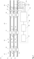
- Fig. 1 shows schematically a high-voltage cable system 20.
- the high-voltage cable system 20 includes three high-voltage cables 21-23, for example for transmitting a three-phase alternating current.
- Each of the three high-voltage cables 21-23 includes an inner conductor and a cable shield.
- the high-voltage cable 21 includes the inner conductor 24 and the cable shield 27, the high-voltage cable 22 includes the inner conductor 25 and the cable shield 28, and the high-voltage cable 23 includes the inner conductor 26 and the cable shield 29.
- Each of the three high-voltage cables 21-23 is divided into several segments. In the in Fig. 1 In the example shown, the three high-voltage cables 21-23 are each divided into four segments 61-64. The number of segments depends on the desired length of the high-voltage cable system 20. Typical segment lengths are in the range of 800-1000 m. With corresponding lengths of the high-voltage cable system 20, several tens to several hundred segments can accordingly be provided.
- Fig. 1 three connections 30, 31 and 32 are shown. In each of these connections 30-32, the conductors of a segment of the corresponding high-voltage cable 21-23 are connected to the following segment of the corresponding high-voltage cable 21-23. In the connection 30, the inner conductor of the segment 61 of the high-voltage cable 21 is therefore connected to the inner conductor of the segment 62 of the high-voltage cable 21.
- connection 30 the inner conductor of the segment 61 of the high-voltage cable 22 is connected to the inner conductor of the segment 62 of the high-voltage cable 22 and the inner conductor of the segment 61 of the high-voltage cable 23 is connected to the inner conductor of the segment 62 of the high-voltage cable 23.
- connections 31 and 32 with respect to segments 62, 63 and 64.
- the cable shield 27 of the segment 62 of the high-voltage cable 21 is connected to the cable shield of the segment 63 of the high-voltage cable 22 via a connection 36.
- the cable shield 28 of the segment 62 of the high-voltage cable 22 is connected via a connection 38 connected to the cable shield of segment 63 of the high-voltage cable 23.
- the cable shield 29 of the segment 62 of the high-voltage cable 23 is connected to the cable shield of the segment 63 of the high-voltage cable 21.
- Corresponding outcrosses are also carried out at connections 30 and 32.
- connections 30-32 have the cable shields grounded.
- a corresponding grounding can be provided at every third connection, for example at connection 32. Large electrical currents can occur at these grounding points, which must be limited in order to reduce thermal loads, for example.
- the cable shields are connected to earth or ground via sheath voltage limiters 39-41 (Sheath Voltage Limiter, SVL).
- a corresponding sheath voltage limiter 39-41 is provided for each cable shield of each high-voltage cable 21-23.
- the sheath voltage limiter 39 couples the cable shield of the high-voltage cable 21 to ground
- the sheath voltage limiter 40 couples the cable shield of the high-voltage cable 22 to ground
- the sheath voltage limiter 41 couples the cable shield of the high-voltage cable 23 to ground.
- the sheath voltage limiters 39-41 can be damaged by voltage peaks.
- a device 50 is provided.
- the device 50 includes a plurality of coupling devices 51-54, for example high frequency current transformers (HFCT).
- HFCT high-frequency current transformers
- HFCT high-frequency current transformers
- HFCT are used in power systems, for example, to monitor partial discharges in insulated high-voltage cables. These are placed around the high-voltage cables, whereby electrical pulses that propagate in the cable shield are detected.
- the underlying physical effect whereby electrical pulses are detected by the HFCT can also be reversed and small electrical pulses can be injected.
- a coupling device 54 for example an HFCT, is provided on a line which connects the sheath voltage limiters 39-41 to a common ground point. Furthermore, a corresponding coupling device 51-53, for example an HFCT, is provided on each high-voltage line 21-23.
- the coupling device 54 serves to feed a test signal into the common ground connection of the sheath voltage limiters 39-41 and the coupling devices 51-53 serve to detect electrical pulses which propagate in the corresponding assigned cable shield of the high-voltage cables 21-23.
- the coupling devices 51-54 are connected to a detection device 55, which, for example, records the signals from the coupling devices 51-53 and converts them into corresponding digital measurement signals. Furthermore, the detection device 55 can be designed to convert digital signals into analog signals, which are fed to the coupling device 54.
- the detection device 55 is coupled to a controller 56, which generates a control signal which is supplied to the detection device 55 in order to generate a test signal based on this control signal, which is supplied to the coupling device 54 for feeding into the common ground connection.
- the measurement signals provided by the detection device 55 can be recorded, stored and processed in the controller 56.
- the information processed by the controller 56 can be displayed using a computer 57 coupled to the controller 56.
- the previously described rough division of functions between the detection device 55, the controller 56 and the computer 57 is merely an example and any other division is conceivable.
- the detection device 55, the controller 56 and the computer 57 can be implemented in a common processing device 58, which includes hardware, software and / or firmware in order to carry out the method described below.
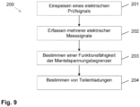
- the method 200 includes method steps 201-204, where method step 204 is optional.
- the processing device 58 controls the coupling device 54 in such a way that a test signal is fed into the common ground line of the sheath voltage limiters 39-41. Due to the inductive feed, the test signal can occur during ongoing operation of the high-voltage cable system 20.
- the test signal preferably has a frequency range of at least 500 kHz to 8 MHz.
- Fig. 2 shows the frequency spectrum of an exemplary test signal. Particularly in the range from 500 kHz to 8 MHz, the test signal can have an almost uniform distribution Have frequency spectrum.
- Fig. 3 shows a corresponding time signal of the test signal Fig. 2 .
- step 202 during ongoing operation of the high-voltage cable system 20, several electrical measurement signals are detected on the cable shields of the high-voltage cables 21-23 by means of the coupling devices 51-53.
- the measurement signals can each be recorded over a period of up to several ⁇ s, for example up to 10 ⁇ s.
- the acquisition of the multiple measurement signals preferably takes place simultaneously.
- An electrical measurement signal is thus recorded for each high-voltage cable 21-23.
- Each of the high-voltage cables 21-23 is used to transmit one phase of a three-phase alternating current.
- a phase A of the three-phase alternating current can be transmitted via the high-voltage cable 21
- a phase B of the three-phase alternating current can be transmitted via the high-voltage cable 22
- a phase C of the three-phase alternating current can be transmitted via the high-voltage cable 23.
- the electrical measurement signals detected on the high-voltage cables 21-23 can therefore be assigned to phases A, B and C.
- corresponding frequency spectra can be determined using a frequency analysis, for example a fast Fourier transformation. These frequency spectra determined from the recorded electrical measurement signals can be compared with reference frequency spectra.
- the reference frequency spectra can, for example, be measured and determined beforehand at a time at which it is ensured that the sheath voltage limiters 39-41 and other sheath voltage limiters in the high-voltage cable system 20 are in a proper condition.
- the reference spectra can, for example, be stored in the processing device 58.
- corresponding reference spectra 101, 103 and 105 are shown for phases A, B and C.
- the reference spectra 101, 103 and 105 can, for example, be previously created using the test signal Figures 2 and 3 when commissioning the high-voltage cable system 20 may have been recorded and stored in the processing device 58, for example in the computer 57 or in the detection device 55.
- corresponding reference spectra can be determined at a later point in time, for example by averaging several measurements, or calculated using appropriate simulations.
- a reference measurement to determine the reference spectra 101, 103 and 105 may be required because the electrical network is different for each measurement due to, among other things, the lengths of the cables and the physical properties of associated system components.
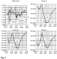
- the frequency spectrums of the electrical measurement signals recorded during operation are in the Fig. 4 marked with reference numerals 102, 104 and 106 for phases A, B and C.
- the sheath voltage limiters 39-41 are in a proper condition, that is, no sheath voltage limiters 39-41 have a short circuit or an interruption. Therefore, the spectra 102, 104 and 106 essentially correspond to the reference spectra 101, 103 and 105, so that in Fig. 4 the spectra 102, 104 and 106 have essentially no deviations from the corresponding reference spectra 101, 103, 105 and are therefore hardly visible.
- the Fig. 4 the differences between the current frequency spectrum and the reference frequency spectrum for phases A, B and C are shown, from which it can be seen that the deviations in this error-free case are actually extremely small, essentially less than 0.2 db.
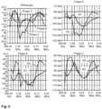
- Fig. 5 shows frequency spectra 112, 114 and 116 for phases A, B and C when one of the sheath voltage limiters 39-41 in the high-voltage cable system 20 has an interruption and is therefore no longer functional. Since the cable shields are coupled to one another via the crossovers 36-38 in the connections 30-32, this interruption from one of the sheath voltage limiters 39-41 not only has an influence on the measurement signal of the corresponding phase, but on all measurement signals of phases A, B and C. How from Fig.
- Fig. 6 shows corresponding frequency spectra 122, 124 and 126 for phases A, B and C for this case.
- the crossovers 36-38 in the connections 30-32 have an influence on all measurement signals of phases A, B and C, even if only one sheath voltage limiter has a short circuit on one of the phases. How out Fig. 6 As can be seen, there are therefore deviations on all phases A, B and C between the frequency spectra 122, 124 and 126 of the electrical measurement signals recorded on the phases and the reference frequency spectra 101, 103 and 105.
- the functionality of the sheath voltage limiters 39-41 can be determined based on the recorded electrical measurement signals.
- the functionality of the sheath voltage limiters 39-41 can be determined based on comparisons between the frequency spectra of the detected electrical measurement signals and the reference frequency spectra. For example, cross-correlations between the frequency spectrum of the detected electrical measurement signals and the reference frequency spectrum can be determined for each phase A, B and C. If the frequency spectra of the detected electrical measurement signals correlate with the reference frequency spectra, the sheath voltage limiters 39-41 are functional. If the sheath voltage limiters 39-41 are faulty, the value of the cross-correlation drops.
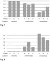
- Fig. 7 shows exemplary cross-correlations for the three phases A, B and C for those in the Figures 4-6 presented cases, the error-free case of Fig. 4 , the case of an interrupted sheath voltage limiter Fig. 5 and the case of a sheath voltage limiter with a short circuit Fig. 6 .
- the correlation value for each of phases A, B and C is approximately one.
- the correlation value is significantly lower than one, for example in the range of 0.8 for the case of the interrupted sheath voltage limiter and in the range of 0.3-0.6 for the case of the sheath voltage limiter with short circuit.
- the processing device 58 can, for example, determine the correlation values for phases A, B and C and compare them with a threshold value, for example with a threshold value of 0.9, and indicate a healthy state of the sheath voltage limiters 39-41 if the correlation values are each above the threshold value , and otherwise display an error.
- a threshold value for example with a threshold value of 0.9
- the functionality of the sheath voltage limiters 39-41 can be determined in step 203 based on deviations. For example, a deviation between the frequency spectrum of the detected electrical measurement signals and the reference spectrum can be determined for each phase A, B and C. If there are small deviations, the sheath voltage limiters 39-41 are functional.
- Fig. 8 shows example deviations for the three phases A, B and C for those in the Figures 4-6 presented cases, the error-free case of Fig. 4 , the case of an interrupted sheath voltage limiter Fig. 5 and the case of a sheath voltage limiter with a short circuit Fig. 6 . In the error-free case, the deviation for each of the phases A, B and C is approximately zero.
- the deviation is well above zero, for example in the range of 10-35 for the case of the sheath voltage limiter with an open circuit and in the range of 30-60 for the case of the sheath voltage limiter with a short circuit.
- the processing device 58 can, for example, determine the deviations for phases A, B and C and compare them with a threshold value, for example with a threshold of five. A fault-free state of the sheath voltage limiters 39-41 is indicated if the deviations are below the threshold value. Otherwise, a fault condition is issued for the sheath voltage limiters 39-41.
- steps 201-203 described above can be carried out continuously or repeatedly, so that the high-voltage cable system can be continuously examined for defective sheath voltage limiters.
- the recorded measurement signals can be additionally evaluated in order to detect partial discharges in the insulation between the inner conductor and the cable shield of the high-voltage cables 21-23. This detection can also be carried out continuously or repeatedly during ongoing operation of the high-voltage cable system 20.
Landscapes
- Physics & Mathematics (AREA)
- General Physics & Mathematics (AREA)
- Testing Relating To Insulation (AREA)
Claims (15)
- Procédé permettant de vérifier au moins un limiteur de tension de gaine pour au moins un câble haute tension d'un système de câbles haute tension, dans lequel un limiteur de tension de gaine respectif de l'au moins un limiteur de tension de gaine (39-41) est monté entre un blindage de câble (27-29) d'un câble haute tension respectif de l'au moins un câble haute tension (21-23) et une borne de mise à la terre, dans lequel le procédé comprend :- l'injection (201) d'un signal de test électrique au niveau de la borne de mise à la terre,- la détection (202) d'au moins un signal de mesure électrique,
dans lequel un signal de mesure électrique respectif de l'au moins un signal de mesure électrique est détecté au niveau du blindage de câble (27-29) d'un câble haute tension respectif de l'au moins un câble haute tension (21-23), et- la détermination (203) d'une capacité de fonctionnement de l'au moins un limiteur de tension de gaine (39-41) en fonction de l'au moins un signal de mesure électrique détecté. - Procédé selon la revendication 1,
dans lequel l'injection du signal de test électrique et la détection de l'au moins un signal de mesure électrique sont effectuées pendant le fonctionnement du système de câbles haute tension (20). - Procédé selon la revendication 2, comprenant en outre :- la détermination (204) de décharges partielles entre un conducteur interne (24-26) et un blindage de câble (27-28) de l'au moins un câble haute tension (21-23) en fonction de l'au moins un signal de mesure détecté.
- Procédé selon l'une des revendications précédentes,
dans lequel le signal de test comprend un signal de test à large bande comportant une gamme de fréquences allant d'au moins 500 kHz à 8 MHz. - Procédé selon l'une des revendications précédentes,
dans lequel la détermination (203) de la capacité de fonctionnement de l'au moins un limiteur de tension de gaine (39-41) comprend une analyse de fréquence de l'au moins un signal de mesure électrique. - Procédé selon la revendication 5,
dans lequel l'analyse de fréquence comprend une transformation de Fourier rapide. - Procédé selon l'une des revendications précédentes,
dans lequel la détermination (203) de la capacité de fonctionnement de l'au moins un limiteur de tension de gaine (39-41) comprend une comparaison de l'au moins un signal de mesure électrique détecté avec au moins un signal de mesure électrique d'une mesure de référence précédente. - Procédé selon l'une des revendications précédentes,
dans lequel le signal de test électrique est injecté par induction. - Procédé selon l'une des revendications précédentes,
dans lequel l'au moins un signal de mesure électrique est détecté par induction. - Procédé selon l'une des revendications précédentes,dans lequel l'au moins un limiteur de tension de gaine comprend plusieurs limiteurs de tension de gaine,dans lequel le système de câbles haute tension comprend un système de câbles haute tension polyphasé,dans lequel l'au moins un câble haute tension comprend plusieurs câbles haute tension du système de câbles haute tension polyphasé,dans lequel le limiteur de tension de gaine respectif parmi les limiteurs de tension de gaine (39-41) est monté entre le blindage de câble (27-29) du câble haute tension respectif parmi les câbles haute tension (21-23) et la borne de mise à la terre commune,dans lequel l'injection (201) du signal de test électrique comprend l'injection (201) du signal de test électrique au niveau de la borne de mise à la terre commune,dans lequel la détection (202) d'au moins un signal de mesure électrique comprend la détection (202) de plusieurs signaux de mesure électriques, dans lequel un signal de mesure électrique respectif parmi les signaux de mesure électriques est détecté au niveau du blindage de câble (27-29) d'un câble haute tension respectif parmi les câbles haute tension (21-23), etdans lequel la détermination (203) de la capacité de fonctionnement de l'au moins un limiteur de tension de gaine (39-41) comprend la détermination (203) de la capacité de fonctionnement des limiteurs de tension de gaine (39-41) en fonction des signaux de mesure électriques détectés.
- Procédé selon la revendication 10,
dans lequel les signaux de mesure sont détectés simultanément. - Procédé selon l'une des revendications précédentes,
dans lequel l'au moins un signal de mesure est détecté en synchronisme avec l'injection du signal de test électrique. - Dispositif permettant de vérifier au moins un limiteur de tension de gaine pour au moins un câble haute tension d'un système de câbles haute tension,
dans lequel un limiteur de tension de gaine respectif de l'au moins un limiteur de tension de gaine (39-41) est monté entre un blindage de câble (27-29) d'un câble haute tension respectif de l'au moins un câble haute tension (21-23) et une borne de mise à la terre, dans lequel le dispositif (50) comprend :- un premier dispositif de couplage (54) permettant d'injecter un signal de test électrique au niveau de la borne de mise à la terre,- au moins un second dispositif de couplage (51-53) permettant de détecter au moins un signal de mesure électrique, dans lequel un second dispositif de couplage respectif de l'au moins un second dispositif de couplage (51-53) est configuré de telle sorte qu'il détecte un signal de mesure électrique respectif de l'au moins un signal de mesure électrique au niveau du blindage de câble (27-29) d'un câble haute tension respectif de l'au moins un câble haute tension (21-23), et- un dispositif de traitement (58) connecté au premier dispositif de couplage (54) et à l'au moins un second dispositif de couplage (51-53) et configuré pour :générer le signal de test et l'acheminer au premier dispositif de couplage (54), détecter l'au moins un signal de mesure électrique à l'aide de l'au moins un second dispositif de couplage (51-53), etdéterminer une capacité de fonctionnement de l'au moins un limiteur de tension de gaine (39-41) en fonction de l'au moins un signal de mesure électrique détecté. - Dispositif selon la revendication 13,
dans lequel le premier dispositif de couplage (54) et l'au moins un second dispositif de couplage (51-53) comprennent respectivement un transformateur de courant haute fréquence. - Dispositif selon la revendication 13 ou la revendication 14,
dans lequel le dispositif (50) est configuré pour la mise en oeuvre automatique du procédé (200) selon l'une des revendications 1 à 12.
Applications Claiming Priority (2)
| Application Number | Priority Date | Filing Date | Title |
|---|---|---|---|
| ATA50049/2019A AT522128B1 (de) | 2019-01-23 | 2019-01-23 | Überprüfen von Mantelspannungsbegrenzern |
| PCT/EP2020/050718 WO2020151986A1 (fr) | 2019-01-23 | 2020-01-13 | Test de limiteurs de tension de gaine |
Publications (3)
| Publication Number | Publication Date |
|---|---|
| EP3914918A1 EP3914918A1 (fr) | 2021-12-01 |
| EP3914918B1 true EP3914918B1 (fr) | 2024-03-06 |
| EP3914918C0 EP3914918C0 (fr) | 2024-03-06 |
Family
ID=69165395
Family Applications (1)
| Application Number | Title | Priority Date | Filing Date |
|---|---|---|---|
| EP20700706.3A Active EP3914918B1 (fr) | 2019-01-23 | 2020-01-13 | Test de limiteurs de tension de gaine |
Country Status (3)
| Country | Link |
|---|---|
| EP (1) | EP3914918B1 (fr) |
| AT (1) | AT522128B1 (fr) |
| WO (1) | WO2020151986A1 (fr) |
Families Citing this family (1)
| Publication number | Priority date | Publication date | Assignee | Title |
|---|---|---|---|---|
| US11150291B1 (en) | 2021-05-14 | 2021-10-19 | Underground Systems, Inc. | Functional reliability assessment for insulated power cable systems |
Family Cites Families (3)
| Publication number | Priority date | Publication date | Assignee | Title |
|---|---|---|---|---|
| DE19629481B4 (de) * | 1996-07-12 | 2006-07-06 | Pirelli Cavi E Sistemi S.P.A. | Schaltungsanordnung für eine Hochspannungskabelanlage |
| KR100988267B1 (ko) * | 2008-10-29 | 2010-10-18 | 한빛이디에스(주) | 지중송전계통 절연통보호장치 상시 진단 장치 |
| EP2392934B1 (fr) * | 2010-06-02 | 2019-02-06 | Omicron Energy Solutions GmbH | Procédé et dispositif de surveillance d'un parafoudre d'un système de câble |
-
2019
- 2019-01-23 AT ATA50049/2019A patent/AT522128B1/de active
-
2020
- 2020-01-13 EP EP20700706.3A patent/EP3914918B1/fr active Active
- 2020-01-13 WO PCT/EP2020/050718 patent/WO2020151986A1/fr not_active Ceased
Also Published As
| Publication number | Publication date |
|---|---|
| AT522128A1 (de) | 2020-08-15 |
| AT522128B1 (de) | 2024-07-15 |
| WO2020151986A1 (fr) | 2020-07-30 |
| EP3914918A1 (fr) | 2021-12-01 |
| EP3914918C0 (fr) | 2024-03-06 |
Similar Documents
| Publication | Publication Date | Title |
|---|---|---|
| EP4127744B1 (fr) | Circuit électrique | |
| EP2392934B1 (fr) | Procédé et dispositif de surveillance d'un parafoudre d'un système de câble | |
| EP3658925B1 (fr) | Procédé et dispositif d'essai pour la mesure d'impulsions de décharge partielle d'un câble blindé | |
| EP2863553B1 (fr) | Dispositif de couplage pour coupler un dispositif de courant porteur en ligne et un dispositif de mesure à un réseau d'alimentation, et un noeud de mesure | |
| EP3338099B1 (fr) | Procédé et système de mesure destiné à la mesure de décharges partielles des connecteurs et utilisation pour des connecteurs d'un véhicule ferroviaire | |
| DE2349982A1 (de) | Schaltung zur unterdrueckung von rauschsignalen und verfahren zur eichung der schaltung | |
| EP3499253A1 (fr) | Trajet de câble sous-marin et procédé de détermination d'une décharge partielle électrique dans un trajet de câble sous-marin | |
| DE102017104110B4 (de) | Verfahren und Vorrichtung zur Verlustfaktorüberwachung von Kondensatordurchführungen | |
| EP2930522A1 (fr) | Procédé et dispositif de diagnostic à résolution spatiale | |
| EP2863236B1 (fr) | Système de contrôle pour composants haute tension | |
| EP3069359B1 (fr) | Procédé et dispositif de surveillance de condensateurs de traversée pour réseau de courant alternatif triphasé | |
| EP0662220B1 (fr) | Decouplage d'un signal d'erreur haute frequence d'un champ electromagnetique haute frequence dans une machine electrique de grande dimension | |
| EP0974846A2 (fr) | Procédé pour détecter des défauts de montage ou de calibration de plusieurs unités d'isolation de signaux dans un ou plusieurs systèmes de décharge partielle | |
| EP3451477A1 (fr) | Détection d'une erreur dans un système de transmission de courant continu | |
| AT522128B1 (de) | Überprüfen von Mantelspannungsbegrenzern | |
| EP3014291B1 (fr) | Contrôle de la terminaison de conducteurs partiels de barres de stator de machines électriques | |
| EP2375543A1 (fr) | Procédé de surveillance d'une ligne de transport d'énergie, suppression de bruit par transmission répété de données | |
| WO2019179645A1 (fr) | Procédé et ensemble de mesure destiné à la détection d'une perturbation électromagnétique sur l'âme dun conducteur électrique | |
| EP4484967B1 (fr) | Dispositif de test de tension capacitif | |
| EP0745862A2 (fr) | Procédé et appareil pour déterminer les propriétés d'isolation d'objets à examiner | |
| EP3269015A1 (fr) | Procédé de détermination d'état et de localisation de défauts sur des dérivations isolées installées dans un système de protection extérieure contre la foudre | |
| DE102017212476B4 (de) | Kabel mit Mantelanordnung zur Biegungserkennung, Anordnung zur Messung einer Biegung eines Kabels und Verfahren zur Messung einer Biegung eines Kabels | |
| EP2942632A1 (fr) | Détection de décharges partielles | |
| EP2553477B1 (fr) | Dispositif et procédé de diagnostic d'objets de mesure en utilisant une tension de mesure | |
| EP3300201A1 (fr) | Procédé et dispositif destinés à la surveillance d'un dispositif de transmission d'énergie |
Legal Events
| Date | Code | Title | Description |
|---|---|---|---|
| STAA | Information on the status of an ep patent application or granted ep patent |
Free format text: STATUS: UNKNOWN |
|
| STAA | Information on the status of an ep patent application or granted ep patent |
Free format text: STATUS: THE INTERNATIONAL PUBLICATION HAS BEEN MADE |
|
| PUAI | Public reference made under article 153(3) epc to a published international application that has entered the european phase |
Free format text: ORIGINAL CODE: 0009012 |
|
| STAA | Information on the status of an ep patent application or granted ep patent |
Free format text: STATUS: REQUEST FOR EXAMINATION WAS MADE |
|
| 17P | Request for examination filed |
Effective date: 20210716 |
|
| AK | Designated contracting states |
Kind code of ref document: A1 Designated state(s): AL AT BE BG CH CY CZ DE DK EE ES FI FR GB GR HR HU IE IS IT LI LT LU LV MC MK MT NL NO PL PT RO RS SE SI SK SM TR |
|
| DAV | Request for validation of the european patent (deleted) | ||
| DAX | Request for extension of the european patent (deleted) | ||
| P01 | Opt-out of the competence of the unified patent court (upc) registered |
Effective date: 20230324 |
|
| GRAP | Despatch of communication of intention to grant a patent |
Free format text: ORIGINAL CODE: EPIDOSNIGR1 |
|
| STAA | Information on the status of an ep patent application or granted ep patent |
Free format text: STATUS: GRANT OF PATENT IS INTENDED |
|
| INTG | Intention to grant announced |
Effective date: 20230920 |
|
| GRAS | Grant fee paid |
Free format text: ORIGINAL CODE: EPIDOSNIGR3 |
|
| GRAA | (expected) grant |
Free format text: ORIGINAL CODE: 0009210 |
|
| STAA | Information on the status of an ep patent application or granted ep patent |
Free format text: STATUS: THE PATENT HAS BEEN GRANTED |
|
| AK | Designated contracting states |
Kind code of ref document: B1 Designated state(s): AL AT BE BG CH CY CZ DE DK EE ES FI FR GB GR HR HU IE IS IT LI LT LU LV MC MK MT NL NO PL PT RO RS SE SI SK SM TR |
|
| REG | Reference to a national code |
Ref country code: CH Ref legal event code: EP |
|
| REG | Reference to a national code |
Ref country code: IE Ref legal event code: FG4D Free format text: LANGUAGE OF EP DOCUMENT: GERMAN |
|
| REG | Reference to a national code |
Ref country code: DE Ref legal event code: R096 Ref document number: 502020007239 Country of ref document: DE |
|
| U01 | Request for unitary effect filed |
Effective date: 20240325 |
|
| U07 | Unitary effect registered |
Designated state(s): AT BE BG DE DK EE FI FR IT LT LU LV MT NL PT SE SI Effective date: 20240404 |
|
| P04 | Withdrawal of opt-out of the competence of the unified patent court (upc) registered |
Effective date: 20240412 |
|
| PG25 | Lapsed in a contracting state [announced via postgrant information from national office to epo] |
Ref country code: GR Free format text: LAPSE BECAUSE OF FAILURE TO SUBMIT A TRANSLATION OF THE DESCRIPTION OR TO PAY THE FEE WITHIN THE PRESCRIBED TIME-LIMIT Effective date: 20240607 |
|
| PG25 | Lapsed in a contracting state [announced via postgrant information from national office to epo] |
Ref country code: RS Free format text: LAPSE BECAUSE OF FAILURE TO SUBMIT A TRANSLATION OF THE DESCRIPTION OR TO PAY THE FEE WITHIN THE PRESCRIBED TIME-LIMIT Effective date: 20240606 Ref country code: HR Free format text: LAPSE BECAUSE OF FAILURE TO SUBMIT A TRANSLATION OF THE DESCRIPTION OR TO PAY THE FEE WITHIN THE PRESCRIBED TIME-LIMIT Effective date: 20240306 |
|
| PG25 | Lapsed in a contracting state [announced via postgrant information from national office to epo] |
Ref country code: ES Free format text: LAPSE BECAUSE OF FAILURE TO SUBMIT A TRANSLATION OF THE DESCRIPTION OR TO PAY THE FEE WITHIN THE PRESCRIBED TIME-LIMIT Effective date: 20240306 |
|
| PG25 | Lapsed in a contracting state [announced via postgrant information from national office to epo] |
Ref country code: RS Free format text: LAPSE BECAUSE OF FAILURE TO SUBMIT A TRANSLATION OF THE DESCRIPTION OR TO PAY THE FEE WITHIN THE PRESCRIBED TIME-LIMIT Effective date: 20240606 Ref country code: NO Free format text: LAPSE BECAUSE OF FAILURE TO SUBMIT A TRANSLATION OF THE DESCRIPTION OR TO PAY THE FEE WITHIN THE PRESCRIBED TIME-LIMIT Effective date: 20240606 Ref country code: HR Free format text: LAPSE BECAUSE OF FAILURE TO SUBMIT A TRANSLATION OF THE DESCRIPTION OR TO PAY THE FEE WITHIN THE PRESCRIBED TIME-LIMIT Effective date: 20240306 Ref country code: GR Free format text: LAPSE BECAUSE OF FAILURE TO SUBMIT A TRANSLATION OF THE DESCRIPTION OR TO PAY THE FEE WITHIN THE PRESCRIBED TIME-LIMIT Effective date: 20240607 Ref country code: ES Free format text: LAPSE BECAUSE OF FAILURE TO SUBMIT A TRANSLATION OF THE DESCRIPTION OR TO PAY THE FEE WITHIN THE PRESCRIBED TIME-LIMIT Effective date: 20240306 |
|
| PG25 | Lapsed in a contracting state [announced via postgrant information from national office to epo] |
Ref country code: IS Free format text: LAPSE BECAUSE OF FAILURE TO SUBMIT A TRANSLATION OF THE DESCRIPTION OR TO PAY THE FEE WITHIN THE PRESCRIBED TIME-LIMIT Effective date: 20240706 |
|
| PG25 | Lapsed in a contracting state [announced via postgrant information from national office to epo] |
Ref country code: SM Free format text: LAPSE BECAUSE OF FAILURE TO SUBMIT A TRANSLATION OF THE DESCRIPTION OR TO PAY THE FEE WITHIN THE PRESCRIBED TIME-LIMIT Effective date: 20240306 |
|
| PG25 | Lapsed in a contracting state [announced via postgrant information from national office to epo] |
Ref country code: CZ Free format text: LAPSE BECAUSE OF FAILURE TO SUBMIT A TRANSLATION OF THE DESCRIPTION OR TO PAY THE FEE WITHIN THE PRESCRIBED TIME-LIMIT Effective date: 20240306 |
|
| PG25 | Lapsed in a contracting state [announced via postgrant information from national office to epo] |
Ref country code: PL Free format text: LAPSE BECAUSE OF FAILURE TO SUBMIT A TRANSLATION OF THE DESCRIPTION OR TO PAY THE FEE WITHIN THE PRESCRIBED TIME-LIMIT Effective date: 20240306 |
|
| PG25 | Lapsed in a contracting state [announced via postgrant information from national office to epo] |
Ref country code: SK Free format text: LAPSE BECAUSE OF FAILURE TO SUBMIT A TRANSLATION OF THE DESCRIPTION OR TO PAY THE FEE WITHIN THE PRESCRIBED TIME-LIMIT Effective date: 20240306 |
|
| PG25 | Lapsed in a contracting state [announced via postgrant information from national office to epo] |
Ref country code: SM Free format text: LAPSE BECAUSE OF FAILURE TO SUBMIT A TRANSLATION OF THE DESCRIPTION OR TO PAY THE FEE WITHIN THE PRESCRIBED TIME-LIMIT Effective date: 20240306 Ref country code: SK Free format text: LAPSE BECAUSE OF FAILURE TO SUBMIT A TRANSLATION OF THE DESCRIPTION OR TO PAY THE FEE WITHIN THE PRESCRIBED TIME-LIMIT Effective date: 20240306 Ref country code: RO Free format text: LAPSE BECAUSE OF FAILURE TO SUBMIT A TRANSLATION OF THE DESCRIPTION OR TO PAY THE FEE WITHIN THE PRESCRIBED TIME-LIMIT Effective date: 20240306 Ref country code: PL Free format text: LAPSE BECAUSE OF FAILURE TO SUBMIT A TRANSLATION OF THE DESCRIPTION OR TO PAY THE FEE WITHIN THE PRESCRIBED TIME-LIMIT Effective date: 20240306 Ref country code: IS Free format text: LAPSE BECAUSE OF FAILURE TO SUBMIT A TRANSLATION OF THE DESCRIPTION OR TO PAY THE FEE WITHIN THE PRESCRIBED TIME-LIMIT Effective date: 20240706 Ref country code: CZ Free format text: LAPSE BECAUSE OF FAILURE TO SUBMIT A TRANSLATION OF THE DESCRIPTION OR TO PAY THE FEE WITHIN THE PRESCRIBED TIME-LIMIT Effective date: 20240306 |
|
| REG | Reference to a national code |
Ref country code: DE Ref legal event code: R097 Ref document number: 502020007239 Country of ref document: DE |
|
| PLBE | No opposition filed within time limit |
Free format text: ORIGINAL CODE: 0009261 |
|
| STAA | Information on the status of an ep patent application or granted ep patent |
Free format text: STATUS: NO OPPOSITION FILED WITHIN TIME LIMIT |
|
| 26N | No opposition filed |
Effective date: 20241209 |
|
| U20 | Renewal fee for the european patent with unitary effect paid |
Year of fee payment: 6 Effective date: 20250127 |
|
| REG | Reference to a national code |
Ref country code: CH Ref legal event code: PL |
|
| PG25 | Lapsed in a contracting state [announced via postgrant information from national office to epo] |
Ref country code: MC Free format text: LAPSE BECAUSE OF FAILURE TO SUBMIT A TRANSLATION OF THE DESCRIPTION OR TO PAY THE FEE WITHIN THE PRESCRIBED TIME-LIMIT Effective date: 20240306 |
|
| GBPC | Gb: european patent ceased through non-payment of renewal fee |
Effective date: 20250113 |
|
| PG25 | Lapsed in a contracting state [announced via postgrant information from national office to epo] |
Ref country code: GB Free format text: LAPSE BECAUSE OF NON-PAYMENT OF DUE FEES Effective date: 20250113 |
|
| PG25 | Lapsed in a contracting state [announced via postgrant information from national office to epo] |
Ref country code: CH Free format text: LAPSE BECAUSE OF NON-PAYMENT OF DUE FEES Effective date: 20250131 |
|
| PG25 | Lapsed in a contracting state [announced via postgrant information from national office to epo] |
Ref country code: IE Free format text: LAPSE BECAUSE OF NON-PAYMENT OF DUE FEES Effective date: 20250113 |
|
| U20 | Renewal fee for the european patent with unitary effect paid |
Year of fee payment: 7 Effective date: 20260119 |
|
| PG25 | Lapsed in a contracting state [announced via postgrant information from national office to epo] |
Ref country code: CY Free format text: LAPSE BECAUSE OF FAILURE TO SUBMIT A TRANSLATION OF THE DESCRIPTION OR TO PAY THE FEE WITHIN THE PRESCRIBED TIME-LIMIT Effective date: 20240306 |
|
| PG25 | Lapsed in a contracting state [announced via postgrant information from national office to epo] |
Ref country code: TR Free format text: LAPSE BECAUSE OF FAILURE TO SUBMIT A TRANSLATION OF THE DESCRIPTION OR TO PAY THE FEE WITHIN THE PRESCRIBED TIME-LIMIT Effective date: 20240306 |