EP0745862A2 - Procédé et appareil pour déterminer les propriétés d'isolation d'objets à examiner - Google Patents
Procédé et appareil pour déterminer les propriétés d'isolation d'objets à examiner Download PDFInfo
- Publication number
- EP0745862A2 EP0745862A2 EP96108516A EP96108516A EP0745862A2 EP 0745862 A2 EP0745862 A2 EP 0745862A2 EP 96108516 A EP96108516 A EP 96108516A EP 96108516 A EP96108516 A EP 96108516A EP 0745862 A2 EP0745862 A2 EP 0745862A2
- Authority
- EP
- European Patent Office
- Prior art keywords
- energy
- frequency
- voltage
- resonant circuit
- test object
- Prior art date
- Legal status (The legal status is an assumption and is not a legal conclusion. Google has not performed a legal analysis and makes no representation as to the accuracy of the status listed.)
- Ceased
Links
Images



Classifications
-
- G—PHYSICS
- G01—MEASURING; TESTING
- G01R—MEASURING ELECTRIC VARIABLES; MEASURING MAGNETIC VARIABLES
- G01R31/00—Arrangements for testing electric properties; Arrangements for locating electric faults; Arrangements for electrical testing characterised by what is being tested not provided for elsewhere
- G01R31/12—Testing dielectric strength or breakdown voltage ; Testing or monitoring effectiveness or level of insulation, e.g. of a cable or of an apparatus, for example using partial discharge measurements; Electrostatic testing
- G01R31/1227—Testing dielectric strength or breakdown voltage ; Testing or monitoring effectiveness or level of insulation, e.g. of a cable or of an apparatus, for example using partial discharge measurements; Electrostatic testing of components, parts or materials
- G01R31/1263—Testing dielectric strength or breakdown voltage ; Testing or monitoring effectiveness or level of insulation, e.g. of a cable or of an apparatus, for example using partial discharge measurements; Electrostatic testing of components, parts or materials of solid or fluid materials, e.g. insulation films, bulk material; of semiconductors or LV electronic components or parts; of cable, line or wire insulation
- G01R31/1272—Testing dielectric strength or breakdown voltage ; Testing or monitoring effectiveness or level of insulation, e.g. of a cable or of an apparatus, for example using partial discharge measurements; Electrostatic testing of components, parts or materials of solid or fluid materials, e.g. insulation films, bulk material; of semiconductors or LV electronic components or parts; of cable, line or wire insulation of cable, line or wire insulation, e.g. using partial discharge measurements
Definitions
- the invention relates to a method and a device for determining the insulation properties of test objects, in particular the insulation properties of cables or cable systems in the medium-voltage or high-voltage range to be examined.
- insulated cables and cable systems composed of such cables and possibly other parts, such as sets, play an important role.
- a fault in such a cable or cable system can be caused by the power failure, e.g. in the industrial sector, in traffic, in heating and cooling systems, in households, public lighting, etc., far more expensive than the repair of the actual damage. Accordingly, high demands are placed on the operational safety of such cables or cable systems.
- Such a system for testing the dielectric strength of installed plastic cables using an alternating test voltage with a low alternating frequency (0.1 to 10 Hz) is known from DE 37 00 647 A1.
- This system works with a DC voltage source.
- the DC voltage it supplies represents one of the polarities (eg the positive) of the alternating test voltage.
- the cable is connected directly to the DC voltage source.
- the capacitance formed by the cable to be tested is connected to an oscillating circuit with an inductance.
- the resonant circuit is initially separated by a switch.
- the capacitance discharges via the inductance and, as a result of an overshoot, charges up to a voltage with opposite (negative) polarity. This represents the test voltage of the other polarity.
- An oscillation after reaching the maximum negative polarity is prevented, so that the cable is subjected to the test voltage of negative polarity for a long time. Only after this long time has elapsed can this discharge process be repeated in the opposite direction and the cable be positively charged again, in order to then be connected again to the DC voltage source and to remain on the positive test voltage for a long time. This cycle is repeated several times.
- Tests with oscillating voltage pulses are also known, which repeatedly place the system or the cable system under a rapidly decaying voltage wave oscillating at approximately 1-10 kHz.
- the error detection rate is also limited here, both because of the high frequency and the short exposure times.
- the good dielectric properties and in particular the low losses of modern plastic-insulated cables now make it possible to assemble resonant circuits with a resonance frequency close to the operational level, in which the cable or cable system to be tested has the capacity and a transportable capacity Choke forms the inductance.
- the power required to continuously supply the resonant circuit is smaller than in the above case of non-resonant exposure at a frequency close to the operational level.
- the supply can take place with a predetermined frequency (in particular mains frequency and thus also the operating frequency); then, however, the inductance - which is relatively complex - must be designed to be adjustable in order to be able to match the resonance frequency precisely to the feed frequency.
- a frequency-adjustable feed means e.g. a mains-powered converter
- a disadvantage is that they can also damage faultless test objects. This is of little importance for new test objects, as these generally cause a short electrical overload. Survive without permanent changes and shortening the lifespan.
- the invention is based on the technical problem of providing a method for determining insulation properties of test objects, in particular cables or cable systems, in particular in the high-voltage range, by means of which these disadvantages can be overcome. This also includes the provision of a corresponding device.
- step c) an electrical variable (or several electrical variables) is generally measured, such as the current flowing through the test object (which is generally equal to the current flowing in the resonant circuit) or the voltage drop across the test object.
- the freedom from interference achieved in this way allows even the smallest deviations from the purely sinusoidal vibration that actually occur to be ascribed to the influence of the insulation of the test object, more precisely to the non-linear electrical behavior of the insulation. (With an appropriate design, the inductance can be operated in the non-saturation range of any iron cores that may be present, so that it behaves practically linear). This means that measurements of the smallest signals and non-sinusoidal (more precisely: changing the sinusoidal) contributions that carry information about the insulation material (such as partial discharge signals) and are conventionally completely spilled by external interference can also be carried out on site.
- the application of overvoltages to the test object can generally be avoided in the method according to the invention; the operating voltage of the test object or even a lower voltage is usually sufficient.
- the uncoupling or switching off in step b) can therefore take place before, at or shortly after the operating voltage is reached. If desired, the method can also be carried out in the overvoltage range.
- test objects e.g. Cables or cable systems including their system components such as connecting sleeves, cable terminations and other sets, but also pure dielectrics, which are only brought into the field of a capacitor for measurement.
- a medium-voltage or high-voltage cable serving as a test object is a capacitor, namely an elongated coaxial capacitor:
- the conductive core of the cable forms one capacitor electrode, an outer semiconducting layer of the cable forms the other.
- the cable insulation in between forms a dielectric between the capacitor electrodes.
- the resonant circuit required for the method will not be available from the outset, but must first be set up by connecting the cable or cable system to be tested with the inductor.
- the method can also start from an existing resonant circuit, for example if the aging of a specific test object is to be continuously researched in the laboratory.
- the energy feed device is decoupled and / or switched off.
- a decoupling is the disconnection of a frequency converter serving the energy feed from the resonant circuit, for example with the help of one or more reed relays arranged in the energy feed line.
- An example of a switch-off is the opening of the electronic switches of the frequency converter responsible for frequency conversion (the resonant circuit itself is not interrupted here). In the case of a thyristor-controlled converter, the shutdown is achieved simply by the fact that the thyristors are no longer fired. In effect, this corresponds to a "detachment".
- the resonant circuit formed by cables and inductance is temporarily decoupled from the external voltage source.
- this only serves to be able to generate test voltages with two different polarities with the help of an external voltage source with only one polarity.
- the resonant circuit is only needed to reverse the polarity of the cable for only half an oscillation period.
- the polarity reversal process itself is irrelevant for the measurement, since this system is only concerned with determining any breakdowns that can occur during the application of the (quasi-stationary) positive or negative test voltage. This goes in a different direction than the invention.
- the method according to the invention is preferably carried out on site due to its excellent freedom from faults and at the same time low system expenditure (claim 2).
- the suitability for on-site testing is a particularly advantageous aspect, since this is the only way to test cables and cable systems that have already been installed with reasonable effort.
- the resonant circuit is preferably supplied with an alternating variable, in particular an essentially sinusoidal alternating variable.
- the feed energy in the frequency deviate from the resonance frequency of the resonant circuit or also be broadband.
- an energy feed-in frequency is advantageously chosen to be essentially equal to the resonance frequency of the resonant circuit. Basically, this can be done by adapting the resonance frequency to the given energy feed-in frequency, for example by changing the inductance.
- the energy is particularly preferably taken from a network and converted to an alternating variable with a resonant frequency (claim 3).
- the resonance frequency must either be known from the outset or first determined, for example by measuring electrical quantities in the resonant circuit (e.g. current or voltage) and simultaneously changing the energy feed frequency until the electrical quantity reaches an extreme value, e.g. has reached a maximum value.
- electrical quantities in the resonant circuit e.g. current or voltage
- the feed energy can be sent directly to a power generator, e.g. be removed from a mobile power-driven generator set.
- a power generator e.g. be removed from a mobile power-driven generator set.
- the particularly preferred withdrawal of energy from a network usually a 50 or 60 Hz network, has the advantage that no corresponding power generator or the like has to be carried along for the on-site inspection.
- the resonance frequency is advantageously selected in the range of the frequency with which the test object is exposed to an alternating field in normal operation (claim 4).
- the test frequency is in a range tolerable deviation of +/- 30 Hz from the operating frequency (generally 50 or 60 Hz).
- the resonance frequency of the resonant circuit is preferably continuously monitored and the energy feed frequency is regulated to the resonance frequency (claim 5). This can ensure that changes in the resonance frequency can be compensated for during the process and thus the energy supply always optimal, i.e. at resonance frequency.
- the sequence of process steps a), b) and c) is particularly advantageously carried out repeatedly (claim 6), e.g. more than 10 to 1000 times.
- this enables randomly distributed processes, such as Partial discharges, reduce the statistical measurement error, and on the other hand with non-randomly distributed, e.g. periodic processes by adding the individual measurements in phase improve the signal-to-noise ratio.
- the energy feed-in is preferably carried out in a controlled manner, namely by performing step a) until a voltage dropping at the test object is an initial level for the test, e.g. the operating voltage, reached and performing step b) for an adjustable time or number of periods (claim 7).
- a voltage dropping at the test object is an initial level for the test, e.g. the operating voltage, reached and performing step b) for an adjustable time or number of periods (claim 7).
- a voltage dropping at the test object e.g. the operating voltage
- step b for an adjustable time or number of periods
- At least one further inductance can preferably be added to the resonant circuit and / or at least one further energy feed device (claim 8). On the one hand, this enables the resonance frequency of the resonant circuit to be adjusted over a larger range. For bigger ones Power can be connected in parallel to several energy feed devices.
- the method according to the invention can be used to carry out the most varied types of measurements in step c). Two types of measurement mentioned below are particularly advantageous.
- partial discharges can advantageously be measured with the method in step c) (claim 9).
- partial discharges can occur at transitions between different system components, such as cables and fittings (connecting sleeves, cable terminations, etc.), for example if dirt or air spaces are enclosed at their separating surfaces.
- Various aging processes and material changes in the material can also lead to partial discharges. Partial discharges erode the insulation in the long run, creating growing channels that lead to (full) breakdown in an intensifying process.
- high alternating voltage eg operating voltage close to the operating frequency
- the partial discharges appear on the outside in the form of very small voltage pulses, which are superimposed on the alternating voltage dropping at the test object.
- the ratio of these pulses to the applied voltage is typically 1/10 7 .
- external interference has made it virtually impossible to detect these small signals on site. With the method according to the invention, however, this is because of this extensive freedom from interference possible.
- the partial discharge signals rise very steeply, so they can be separated from the low-frequency high-voltage wave, for example with the help of a high pass.
- Another advantageous measurement consists in Fourier transforming in method step c) an electrical quantity which carries information about insulation properties of the test object (claim 10).
- a Fourier spectrum of this size is obtained, which is used to identify material-specific properties and material changes.
- insulation diagnostics and in particular early detection of a “water tree” formation (“water tree” means a tree-shaped structural change in the insulation material due to water that has diffused in) and other aging processes inside the material.
- the leakage currents are generally complicated nonlinear functions of the applied voltage; Ohm's law applies to so they don't. As a result, the leakage current with a sinusoidal applied voltage has a non-sinusoidal course. Its exact shape varies from material to material. A. Gemant described this phenomenon in the article "Oscillography of currents in insulating materials” in the Archiv für Elektrotechnik, XXIII. Band, 1930, and Fritz Liebscher in the essay "On the dielectric losses and the curve shape of the currents in layered insulating materials at high alternating field strengths of 50 Hz", 1942. However, this has not gained any practical importance.
- the electrical variable is the leakage current (I pw + I R ) flowing through the test object, the total current (I c ), the capacitive current (I Co + I pc ) or one of these currents used without the fundamental wave component (claim 11).
- the leakage current carries information about the non-linearities of the material of the test object. It is therefore primarily used as the basis for the measurement. However, since it also forms part of the total current, this can in principle also be used for the measurement. It is also not excluded that the capacitive component of the polarization current I pc also contains non-linearities and so the entire capacitive current (I Co + I pc ) can be used for the measurement.
- the transfer function of the measuring device is preferably determined. If a Fourier transformation is carried out, the influence of the transfer function of the measuring device on the result of the Fourier transformation is eliminated, so that a so-called resulting Fourier spectrum results (claim 12).
- the measuring device for example a measuring bridge, which has to be adjusted to a different fundamental frequency for each measurement
- the transfer function of the measuring device is determined for each setting, for example by means of a signal generator.
- the original signal which is independent of the measuring device, can be calculated back, for example with the aid of a computer. Different measurements can thus be compared, regardless of which measuring device and which one Setting they were determined.
- the Fourier spectrum resulting from the Fourier transformation or the resulting Fourier spectrum is analyzed and / or the spectrum is compared with a spectrum obtained earlier (with the same test object) or with a reference spectrum (related to the material of the test object) (claim 13).
- a spectrum obtained earlier with the same test object
- a reference spectrum related to the material of the test object
- a device for determining the insulation properties of test objects in particular a cable or cable system, subject to alternating quantities, in particular in the medium or high voltage range, is provided with at least one inductance with which an oscillating circuit comprising the test object as a capacitance or as part of a capacitance is formed can, at least one energy feed device for feeding energy into the resonant circuit, at least one means for decoupling and / or switching off the energy feed device so that the resonant circuit can oscillate freely with an essentially sinusoidal oscillation at the resonance frequency, and a measuring device for measuring contributions to the oscillation, which deviations from the sinusoidal shape and carry information about insulation properties while the energy supply device is disconnected or switched off (claim 14).
- This device is provided in particular for carrying out the method according to the invention or one of the above-mentioned developments thereof.
- the device is preferably designed to be portable, in particular mobile (claim 15), for example it is built on a truck.
- At least one energy feed-in device is preferably designed to be frequency-adjustable in order to adapt the energy feed-in frequency to the resonance frequency and preferably to be able to take the feed-in energy from a network (claim 16).
- the frequency-adjustable energy feed device can be used to find the resonance frequency. For example, by traversing the frequency from low to high frequencies, it is possible to determine where the resonance frequency is in the resonant circuit by measuring electrical quantities (e.g. current, voltage).
- the device preferably has a control or regulating device, which - in particular optoelectronically - is coupled to the measuring device and / or at least one energy feed device, in order in particular to be able to monitor the resonance frequency of the resonant circuit and to regulate the energy feed frequency to the resonance frequency (claim 18).
- the control or regulating device can also control or regulate the energy supply as a whole and also the measurement of measured variables.
- the optoelectronic coupling of the measuring device to the control or regulating device and / or the optoelectronic coupling of the control or regulating device to the energy feed device achieves a galvanic separation between these inputs and devices. This helps reduce the interference on the sensitive To keep measuring device and next to the control or regulating device minimal.
- the device is preferably provided with means for controlled or regulated repeated energy decoupling and / or switching off and possibly also with means for controlled or regulated repeated energy supply (claim 19).
- One or more transformers can be used to couple in energy, for example, which are connected in the resonant circuit with one winding and with the other with the energy feed device, e.g. a frequency converter or similar are coupled.
- the means for decoupling energy can e.g. electronic or mechanical switches (e.g. reed relays) connected between the frequency converter and the other transformer winding.
- the means for switching off the energy supply device - and also for repeated energy supply can e.g. Be part of a control electronics of the frequency converter, which allow the output of the frequency converter to be switched on and off as required.
- the device preferably has means for Fourier transforming electrical quantities (claim 22). These are preferably used to Fourier transform the resonance vibration with the contributions (or the contributions alone). This can e.g. a hard-wired Fourier analyzer, a suitably equipped and programmed computer or mixed forms of these, possibly with an upstream signal analyzer.
- the means are set up in particular for a fast Fourier analysis (so-called FFT).
- the device is preferably equipped with means for determining the transfer function of the measuring device and - if means for Fourier transformation are provided - with means for eliminating the influence of the transfer function of the measuring device on the result of the Fourier transformation in order to obtain a resulting Fourier spectrum to get (claim 23).
- These can be means, such as a computer, which, on the one hand, carry out the Fourier analysis and, on the other hand, control, for example, a signal generator which in turn operates the measuring device with a signal of a certain amplitude and possibly a phase and a certain frequency (to be passed through).
- the device particularly preferably has means for analyzing the Fourier spectrum of the electrical quantity or the respective resulting Fourier spectrum and / or comparing the respective Fourier spectrum with a previously obtained or a corresponding reference spectrum (claim 24).
- means for analyzing the Fourier spectrum of the electrical quantity or the respective resulting Fourier spectrum and / or comparing the respective Fourier spectrum with a previously obtained or a corresponding reference spectrum (claim 24).
- this includes in particular computers that can analyze or compare the spectra and can therefore use data from earlier measurements or reference data.
- the measures of claim 10 or 22 can generally be advantageous in the case of any type of alternating variable loading - also other than that specified according to claim 1 or 14.
- the reservation is therefore declared to claim the subject matter of claims 10 and 22 and the subclaims referring to them without reference to any of claims 1 to 9 or 14 to 21.
- FIG. 1 shows a capacitance C x to be examined, which represents the test object or can be part of a test object.
- this can be one or more cables or a cable system, but also a dielectric that is introduced into a capacitance and whose insulation properties are to be investigated. It is further assumed that C x is the capacity of a cable or cable system.
- An inductance L and the secondary winding of a transformer 1 are connected in series with the capacitance C x . These elements form a resonant circuit.
- the transformer 1 serves to feed energy into the resonant circuit.
- a measuring device 2 is provided to measure electrical quantities at the capacitance C x .
- An energy feed device 3 can be coupled on the input side to a network with frequency f1, for example 50 or 60 Hz, and is connected on the output side to the primary winding of transformer 1.
- the energy feed device 3 comprises a frequency converter or converter (here a thyristor-controlled frequency converter) which can convert the frequency f1 on the input side into an adjustable frequency f2 on the output side.
- the energy feed device comprises a generator (e.g. driven by an internal combustion engine) which can directly supply the frequency f2.
- a control or regulating device 4 controls the energy supply device 3 and means for switching off the energy supply device 3.
- these means are that the energy supply device 3 can be switched off and are therefore integrated in the latter.
- These means for decoupling can be, for example, electronic or mechanical switches (for example reed relays) which are each connected between the energy feed device and the primary winding of the transformer in order to be able to completely disconnect the former from the resonant circuit.
- the measuring device 2 is coupled to the control or regulating device in order to supply signals to control purposes on the one hand and to be able to be controlled on the other hand.
- step S1 electrical energy is now fed into the resonant circuit at a frequency which essentially corresponds to this resonance frequency, namely by means of the energy feed device 3 via the transformer 1 (FIG. 2, step S1).
- the energy supply device 3 is switched off (for example by no longer firing the thyristors of the frequency converter) and, if necessary, alternatively or additionally disconnected from the transformer 1 so that the resonant circuit continues to oscillate freely with its resonant frequency (step S2). It is therefore no longer connected to the network and possibly not to the (switched-off) energy feed device, so that no more interference can get into the resonant circuit from there.
- the switching off of the energy feed device and / or, if appropriate, its disconnection from the control or regulating device 4 is preferably carried out for one or more oscillation periods, particularly preferably for an adjustable predetermined time or number of oscillation periods, for example 1-300 oscillation periods.
- the control or regulating device 4 switches the energy feed 3 back on or couples it again, so that the voltage is regulated back to the initial level.
- the control device 4 switches on the measurement during the energy feed break.
- the control or regulating device 4 is optoelectronically coupled to the measuring device 2 and / or to the energy feed device 3.
- step S4 the results obtained in the individual measurements are summarized and - as described in detail below - Fourier transformed.
- the result of the Fourier transformation is then analyzed and / or e.g. compared with reference results (step S5).
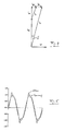
- a capacitive current I Co corresponding to the displacement current in the (imaginary) ideal test object capacitor without dielectric leads 90 ° of the voltage.
- the dielectric which is assumed to be ideally insulating, leads the polarization current I p by less than 90 °.
- a line current I R ultimately results from the current passing through the real dielectric due to its conductivity not completely disappearing, it is in phase with the voltage U and thus contributes to an active power.
- the polarization current I p can be broken down into a component I pw , which is also in phase with the voltage U and thus also contributes to an active power; together with the line current I R it forms the so-called leakage current.
- the other component I pc of the polarization current I p is capacitive, so it leads the voltage U by 90 °.
- the pointer diagram thus results in a leakage current I pw + I R on the one hand and a total capacitive current I Co + I pc on the other hand.
- the tangent of the loss angle ⁇ indicated in FIG. 4 means the ratio of the leakage current I pw + I R to the total capacitive current I Co + I pc .
- This loss factor tan ⁇ is typically in the range 1/1000 to 1/10000 in high-quality high-voltage cables.
- the spectral distribution of the leakage current (ie the distribution the contributions to the resonance vibration, which make it non-sinusoidal, as a function of frequency, with or without a fundamental wave component if necessary) contains highly specific information about the material properties of the insulating material.
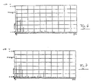
- the Fourier spectrum of the leakage current is, so to speak, a "fingerprint" of the insulating material. You can use it to differentiate between various insulating materials. Since aging processes, water tree formation and other change processes also change the spectral distribution of an insulating material, Fourier analysis of the leakage current can provide information about the progress of such processes and thus about the condition of the cable. For example, FIG. 6 shows the leakage current spectrum of a new cable and FIG.
- FIG. 7 shows the leakage current spectrum of a cable with water tree formation. It can be seen that certain harmonic components in FIG. 7 are considerably more pronounced than in FIG. 6. These characteristic differences allow a highly specific assessment of the cable condition, with certain insulation damage being found long before a breakdown occurs.
- the separation of the total leakage current I pw + I R from the total current I C can be done in particular with bridge circuits.
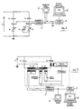
- FIG. 8 shows a measuring device for leakage current analysis with such a bridge circuit, the so-called Schering bridge.
- the leakage current I pw + I R can be separated from the total current I C by means of suitable adjustment.
- C x the capacitance to be examined or the test object in the form of a cable or cable system
- C N designates an ideal capacitance
- R 1 and R 2 each designate an adjustable resistance
- C 2 designates a switchable and adjustable ideal capacitance.
- a differential amplifier 5 is connected between the bridge points A and B, on the one hand to amplify the small signals and on the other hand to switch off the influence of the two bridge points of common voltage levels which could be present with regard to downstream (possibly grounded) devices.
- the time course of the voltage tapped between points A and B can then be viewed using a suitable device, for example an oscilloscope 6.
- the signal at the output of the differential amplifier 5 is fed to a signal analyzer 7.
- the signal processed by the signal analyzer 7 then arrives at a computer 8, which carries out the Fourier transformation and displays the Fourier spectrum.
- the bridge circuit can be operated in two ways:
- the bridge circuit can also be used to measure the capacitance C x and the loss factor tan ⁇ .
- FIG. 9 shows another type of measuring bridge for leakage current analysis, namely a current comparator measuring bridge.
- C x denotes the lossy capacity of the test object
- C N denotes an ideal capacity.
- the bridge is adjusted using variable transformer ratios.
- N 1 , N 2 , N 3 , N 4 denote the number of turns of transformer windings, from which the transformation ratios of the transformers result.
- This circuit is also provided with a differential amplifier 5, an oscilloscope 6, a signal analyzer 7 and a computer 8. Analogously to the measuring device with a Schering bridge, the leakage current I pw + I R can be separated and analyzed.
- FIG. 10 shows a measuring device corresponding to FIG. 8, but which additionally has a circuit for measuring the transfer function of the measuring bridge.
- This measurement of the transfer function is carried out by looking at the measuring bridge circuit alone, ie without connected inductance L and without connected energy feed, that is to say without energy feed device 3 and transformer 1. It proceeds as follows: first the test object is switched into the measuring bridge, then the measuring bridge acted upon with a defined input signal of a certain frequency, and the output signal, that is to say the signal between points A and B or at the output of the differential amplifier, is measured, processed further in signal analyzer 7 and in computer 8 and finally compared with the input signal. By passing through all (practically occurring) frequencies, the transfer function can be derived from this the measuring bridge. Correspondingly, not only can the transfer function of a measuring bridge, but also any other measuring device be determined from this.
- a bridge circuit can generally can only be adjusted for one frequency. From the adjustment setting to the adjustment setting, other frequencies (harmonics) appear damped in different ways. In order to be able to compare the measurement results from different adjustment settings, the influence of these different attenuations should be eliminated.
- the previously determined transfer function of the measuring device is required for each adjustment setting. This can be done, in particular, by measuring the transfer function of the bridge in the respective adjustment setting by means of a signal generator 9 after each measurement. The original, circuit-independent signal is then calculated back using this transfer function with the aid of a computer 8.
- step S1 Another important measurement for the diagnosis of test objects, especially high-voltage cables and systems, is the measurement of partial discharges. They are preferably carried out in the time domain, so generally no devices for Fourier transformation are required.
- the measurement in turn proceeds in such a way that energy is first fed into the resonant circuit (step S1), then the energy feed is disconnected or switched off at a specific voltage (step S2) and then, for example, the voltage drop across the test object is measured (step S3) or is analyzed by means of an oscilloscope 6.
- Partial discharges also lead to deviations from the sinusoid of the oscillating circuit oscillation: They show up in a superimposition of the natural oscillation of the oscillating circuit with individual randomly distributed signals ("peaks") which have a high slope (corresponding to frequencies in the range from 20-200 kHz and higher). These partial discharge signals can therefore easily be separated from the overall signal, for example with the aid of a high pass or band pass.
- the resulting signal can then be examined further.
- the number of partial discharge peaks and their amplitude can give precise information about the state of the insulating material with regard to partial discharges.
- the phase position of the partial discharge peaks relative to the fundamental wave can also carry information about the location of the partial discharge inside the test object.
- corona discharges of non-solid-insulated electrodes e.g. Supplements primarily at the maximum values of the applied voltage, while partial discharge processes inside the insulation material occur predominantly in the region of the zero crossings of the applied voltage.
- FIG. 11 shows an equivalent circuit diagram of a cable or a cable system. This can be imagined as a parallel-series connection of many capacities. Cavities can be symbolized by spark gaps connected in parallel with the capacitances, which are short-circuited by the partial discharges, which can be seen on the outside of the cable clamps in each case in a partial discharge peak described above.
- partial discharges can mainly occur in gas-filled cavities in the insulation, which either occur in a continuous insulating body or at interfaces between two insulating bodies, such as on composite insulation and fittings (such as end closures and connecting sleeves).
- the major part of the faults that occur can be switched off simply and effectively.
- Only atmospheric disturbances cannot be completely suppressed e.g. broadcast signals).
- Such interference is generally relatively small and can also be determined approximately by comparison measurements, for example with the aid of an antenna, and then eliminated from the signal.
Landscapes
- Physics & Mathematics (AREA)
- General Physics & Mathematics (AREA)
- Testing Relating To Insulation (AREA)
Applications Claiming Priority (2)
| Application Number | Priority Date | Filing Date | Title |
|---|---|---|---|
| DE19519746 | 1995-05-30 | ||
| DE1995119746 DE19519746C2 (de) | 1995-05-30 | 1995-05-30 | Verfahren und Vorrichtung zum Bestimmen von Isolationseigenschaften eines Prüfobjekts |
Publications (2)
| Publication Number | Publication Date |
|---|---|
| EP0745862A2 true EP0745862A2 (fr) | 1996-12-04 |
| EP0745862A3 EP0745862A3 (fr) | 1997-10-01 |
Family
ID=7763191
Family Applications (1)
| Application Number | Title | Priority Date | Filing Date |
|---|---|---|---|
| EP96108516A Ceased EP0745862A3 (fr) | 1995-05-30 | 1996-05-29 | Procédé et appareil pour déterminer les propriétés d'isolation d'objets à examiner |
Country Status (2)
| Country | Link |
|---|---|
| EP (1) | EP0745862A3 (fr) |
| DE (1) | DE19519746C2 (fr) |
Cited By (5)
| Publication number | Priority date | Publication date | Assignee | Title |
|---|---|---|---|---|
| EP0990916A4 (fr) * | 1998-04-14 | 2002-01-30 | Furukawa Electric Co Ltd | Procede pour diagnostiquer la deterioration d'un cable electrique |
| US7952362B2 (en) | 2005-10-19 | 2011-05-31 | B2 Electronics Gmbh | Device for measuring the loss factor |
| CN103323752A (zh) * | 2013-06-05 | 2013-09-25 | 广东电网公司电力科学研究院 | 一种干式空心电抗器匝间绝缘缺陷的检测系统 |
| CN108107291A (zh) * | 2017-12-15 | 2018-06-01 | 哈尔滨理工大学 | 一种变压器油纸绝缘多因素联合老化试验装置及其寿命预测方法 |
| CN115980524A (zh) * | 2022-12-29 | 2023-04-18 | 广东电网有限责任公司 | 变压器测试系统 |
Families Citing this family (2)
| Publication number | Priority date | Publication date | Assignee | Title |
|---|---|---|---|---|
| DE10048962B4 (de) * | 2000-10-04 | 2006-12-07 | Omicron Electronics Gmbh | Tragbare Prüfeinrichtung zum Prüfen von mit hohen Spannungen und/oder hohen Strömen zu betreibenden Prüflingen und Prüfsystem |
| DE102012101548B4 (de) * | 2012-02-27 | 2015-11-19 | Maschinenfabrik Reinhausen Gmbh | Prüfsystem und Verfahren für eine induzierte Spannungsprüfung sowie Verlustleistungsmessung von Prüfobjekten der Hochspannungstechnik |
Family Cites Families (4)
| Publication number | Priority date | Publication date | Assignee | Title |
|---|---|---|---|---|
| GB1060643A (en) * | 1963-09-12 | 1967-03-08 | English Electric Co Ltd | Electrical fault detection arrangement |
| DE3700647A1 (de) * | 1986-10-27 | 1988-04-28 | Baur Pruef & Messtech | Schaltungsanordnung zur isolationspruefung verlegter kunststoffkabel |
| SE459059B (sv) * | 1987-09-16 | 1989-05-29 | Asea Ab | Skydd foer hoegresistiva jordfel |
| US5047724A (en) * | 1989-12-19 | 1991-09-10 | Bell Communications Research, Inc. | Power cable arcing fault detection system |
-
1995
- 1995-05-30 DE DE1995119746 patent/DE19519746C2/de not_active Expired - Fee Related
-
1996
- 1996-05-29 EP EP96108516A patent/EP0745862A3/fr not_active Ceased
Cited By (7)
| Publication number | Priority date | Publication date | Assignee | Title |
|---|---|---|---|---|
| EP0990916A4 (fr) * | 1998-04-14 | 2002-01-30 | Furukawa Electric Co Ltd | Procede pour diagnostiquer la deterioration d'un cable electrique |
| US7952362B2 (en) | 2005-10-19 | 2011-05-31 | B2 Electronics Gmbh | Device for measuring the loss factor |
| CN103323752A (zh) * | 2013-06-05 | 2013-09-25 | 广东电网公司电力科学研究院 | 一种干式空心电抗器匝间绝缘缺陷的检测系统 |
| CN103323752B (zh) * | 2013-06-05 | 2016-03-02 | 广东电网公司电力科学研究院 | 一种干式空心电抗器匝间绝缘缺陷的检测系统 |
| CN108107291A (zh) * | 2017-12-15 | 2018-06-01 | 哈尔滨理工大学 | 一种变压器油纸绝缘多因素联合老化试验装置及其寿命预测方法 |
| CN108107291B (zh) * | 2017-12-15 | 2024-03-26 | 哈尔滨理工大学 | 一种变压器油纸绝缘多因素联合老化试验装置及其寿命预测方法 |
| CN115980524A (zh) * | 2022-12-29 | 2023-04-18 | 广东电网有限责任公司 | 变压器测试系统 |
Also Published As
| Publication number | Publication date |
|---|---|
| EP0745862A3 (fr) | 1997-10-01 |
| DE19519746C2 (de) | 1998-06-04 |
| DE19519746A1 (de) | 1996-12-05 |
Similar Documents
| Publication | Publication Date | Title |
|---|---|---|
| DE3856334T2 (de) | Gerät zur Bewertung des Isolationszustandes | |
| DE69919723T2 (de) | Induktiver magnetischer Sensor mit mehreren enggekoppelten Wicklungen | |
| DE69032763T2 (de) | Nutzung eines Magnetkerns für das Messen von Teilentladungen | |
| EP2372857B1 (fr) | Détermination de la partie de courant de fuite d'un courant différentiel | |
| EP2230522B1 (fr) | Procédé et dispositif de surveillance d'isolation d'un réseau isolé terre | |
| DE3606697C2 (de) | Verfahren zum Prüfen der Beschädigung der Isolation eines Hochspannungskabels | |
| EP2863553B1 (fr) | Dispositif de couplage pour coupler un dispositif de courant porteur en ligne et un dispositif de mesure à un réseau d'alimentation, et un noeud de mesure | |
| EP3589964B1 (fr) | Procédé et dispositif pour surveiller les facteurs de pertes de traversées de condensateurs | |
| WO2018050499A1 (fr) | Procédé et dispositif pour déterminer et/ou surveiller l'état d'une huile de transformateur | |
| EP2806279A1 (fr) | Procédé de mesure comprenant un dispositif de mesure pour le diagnostic de câbles et/ou pour le contrôle de câbles | |
| EP3069359B1 (fr) | Procédé et dispositif de surveillance de condensateurs de traversée pour réseau de courant alternatif triphasé | |
| DE19819219C1 (de) | Verfahren und Vorrichtung zur Überwachung einer Elektrodenleitung einer bipolaren Hochstpannungs-Gleichstrom-Übertragungs-Anlage | |
| DE102005025449A1 (de) | Verfahren und Vorrichtung zur Messung einer dielektrischen Antwort eines elektrischen Isoliersystems | |
| DE3751490T2 (de) | Isolationsprüfschaltung für gasisolierte Geräte. | |
| WO2022012989A1 (fr) | Procédé et dispositif pour déterminer un état d'un transformateur condensateur de tension | |
| EP3870983B1 (fr) | Analyse d'état d'un matériel électrique | |
| EP4435442A1 (fr) | Appareil de contrôle et procédé de contrôle d'un câble haute ou moyenne tension | |
| DE19519746C2 (de) | Verfahren und Vorrichtung zum Bestimmen von Isolationseigenschaften eines Prüfobjekts | |
| EP2863236A1 (fr) | Système de contrôle pour composants haute tension | |
| DE19519744A1 (de) | Verfahren und Vorrichtung zum Bestimmen von Isolationseigenschaften von Prüfobjekten | |
| EP2093577B1 (fr) | Procédé et dispositif de test d'un dispositif de technique d'énergie | |
| DD240461B3 (de) | Verfahren zur pruefung von primaerwicklungen von induktiven spannungswandlern | |
| EP0606283B1 (fr) | Procede et dispositif de mesure correspondant pour l'evaluation de l'arc electrique sur les contacts glissants de machines electriques | |
| DE102021112016B3 (de) | Verfahren und Vorrichtung zum Ermitteln einer Erdschlussrichtung | |
| EP3914918B1 (fr) | Test de limiteurs de tension de gaine |
Legal Events
| Date | Code | Title | Description |
|---|---|---|---|
| PUAI | Public reference made under article 153(3) epc to a published international application that has entered the european phase |
Free format text: ORIGINAL CODE: 0009012 |
|
| AK | Designated contracting states |
Kind code of ref document: A2 Designated state(s): AT BE CH DE FI FR IT LI LU NL SE |
|
| PUAL | Search report despatched |
Free format text: ORIGINAL CODE: 0009013 |
|
| AK | Designated contracting states |
Kind code of ref document: A3 Designated state(s): AT BE CH DE FI FR IT LI LU NL SE |
|
| 17P | Request for examination filed |
Effective date: 19980401 |
|
| 17Q | First examination report despatched |
Effective date: 19990414 |
|
| GRAG | Despatch of communication of intention to grant |
Free format text: ORIGINAL CODE: EPIDOS AGRA |
|
| RAP1 | Party data changed (applicant data changed or rights of an application transferred) |
Owner name: SEFAG IXOSIL AG |
|
| STAA | Information on the status of an ep patent application or granted ep patent |
Free format text: STATUS: THE APPLICATION HAS BEEN REFUSED |
|
| 18R | Application refused |
Effective date: 20010608 |