EP3917735B1 - Machine à estamper/perforer - Google Patents
Machine à estamper/perforer Download PDFInfo
- Publication number
- EP3917735B1 EP3917735B1 EP20709467.3A EP20709467A EP3917735B1 EP 3917735 B1 EP3917735 B1 EP 3917735B1 EP 20709467 A EP20709467 A EP 20709467A EP 3917735 B1 EP3917735 B1 EP 3917735B1
- Authority
- EP
- European Patent Office
- Prior art keywords
- punching
- perforating
- piston
- punch
- machine
- Prior art date
- Legal status (The legal status is an assumption and is not a legal conclusion. Google has not performed a legal analysis and makes no representation as to the accuracy of the status listed.)
- Active
Links
Images


Classifications
-
- B—PERFORMING OPERATIONS; TRANSPORTING
- B21—MECHANICAL METAL-WORKING WITHOUT ESSENTIALLY REMOVING MATERIAL; PUNCHING METAL
- B21D—WORKING OR PROCESSING OF SHEET METAL OR METAL TUBES, RODS OR PROFILES WITHOUT ESSENTIALLY REMOVING MATERIAL; PUNCHING METAL
- B21D28/00—Shaping by press-cutting; Perforating
- B21D28/24—Perforating, i.e. punching holes
- B21D28/34—Perforating tools; Die holders
-
- B—PERFORMING OPERATIONS; TRANSPORTING
- B26—HAND CUTTING TOOLS; CUTTING; SEVERING
- B26D—CUTTING; DETAILS COMMON TO MACHINES FOR PERFORATING, PUNCHING, CUTTING-OUT, STAMPING-OUT OR SEVERING
- B26D5/00—Arrangements for operating and controlling machines or devices for cutting, cutting-out, stamping-out, punching, perforating, or severing by means other than cutting
- B26D5/08—Means for actuating the cutting member to effect the cut
- B26D5/12—Fluid-pressure means
-
- B—PERFORMING OPERATIONS; TRANSPORTING
- B26—HAND CUTTING TOOLS; CUTTING; SEVERING
- B26F—PERFORATING; PUNCHING; CUTTING-OUT; STAMPING-OUT; SEVERING BY MEANS OTHER THAN CUTTING
- B26F1/00—Perforating; Punching; Cutting-out; Stamping-out; Apparatus therefor
- B26F1/02—Perforating by punching, e.g. with relatively-reciprocating punch and bed
- B26F1/04—Perforating by punching, e.g. with relatively-reciprocating punch and bed with selectively-operable punches
-
- B—PERFORMING OPERATIONS; TRANSPORTING
- B26—HAND CUTTING TOOLS; CUTTING; SEVERING
- B26F—PERFORATING; PUNCHING; CUTTING-OUT; STAMPING-OUT; SEVERING BY MEANS OTHER THAN CUTTING
- B26F1/00—Perforating; Punching; Cutting-out; Stamping-out; Apparatus therefor
- B26F1/24—Perforating by needles or pins
-
- B—PERFORMING OPERATIONS; TRANSPORTING
- B21—MECHANICAL METAL-WORKING WITHOUT ESSENTIALLY REMOVING MATERIAL; PUNCHING METAL
- B21D—WORKING OR PROCESSING OF SHEET METAL OR METAL TUBES, RODS OR PROFILES WITHOUT ESSENTIALLY REMOVING MATERIAL; PUNCHING METAL
- B21D28/00—Shaping by press-cutting; Perforating
- B21D28/24—Perforating, i.e. punching holes
- B21D28/246—Selection of punches
-
- B—PERFORMING OPERATIONS; TRANSPORTING
- B26—HAND CUTTING TOOLS; CUTTING; SEVERING
- B26D—CUTTING; DETAILS COMMON TO MACHINES FOR PERFORATING, PUNCHING, CUTTING-OUT, STAMPING-OUT OR SEVERING
- B26D5/00—Arrangements for operating and controlling machines or devices for cutting, cutting-out, stamping-out, punching, perforating, or severing by means other than cutting
- B26D2005/002—Performing a pattern matching operation
Definitions
- the present invention relates to a punching/perforating machine for producing a punching/perforating pattern in a fed material unit/web with a punching tool, with a plurality of punching punches/perforating needles arranged in a longitudinal direction in a predetermined grid, which can be moved via a pressure bar which is operatively connected via a control device to a drive unit for producing a punching/perforation stroke transverse to the longitudinal direction, a control block for controlling/activating/deactivating the punching punches/perforating needles by the control device during the punching/perforating process, wherein the punching tool and/or the control block is/are each designed as a separate assembly, which is each arranged separately as a unit and can be detachably fastened within the punching/perforating machine.
- a punching machine is known with several punches, each of which interacts with a die, a drive device for the punch movements and a feed device for the cyclical further movement of the material to be punched through the punching machine. At least one of the punches, preferably all of the punches, is provided with its own drive that can be switched on and off and/or a coupling with the drive device that can be switched on and off.
- the punching machine also has a machine table with several receiving positions for one tool unit each.
- the tool unit has at least one die and at least one punch that can be acted upon by the drive device.
- the tool unit with the die and a punch interacting with the die has its own switchable drive or a switchable coupling device for transmitting the punch drive force.
- a punching processing device for producing a punching pattern comprising an upper die with a punch holder with several punches and with an underlying stripping plate with holes for receiving the ends of the punches projecting from the punch holder in such a way that they can be extended or retracted, and a lower die with holes into which the ends of the punches enter during the punching process.
- Feed devices move a material unit inserted between the lower die and the stripping plate intermittently synchronously with the punching process.
- the punches are held in the punch holder so that they can be moved up and down, with the tops of the heads of the punches being smooth or flush with the upper surface of the punch holder.
- Press heads are used with a head surface for pressing down the punch heads.
- a depression-preventing stepped portion is movable by die head driving means such that either the head surface or the blunted portion is aligned with the respective punch head.
- the die head driving means are controlled by a control circuit which generates binary-coded machining data corresponding to the punching pattern.
- a device for punching workpieces with an upper tool and a lower tool wherein the upper tool is movable relative to the lower tool, wherein several punching dies and adjusting elements associated therewith are arranged in the upper tool, which can be moved between an actuating position in which the punching dies are moved when the Upper tool relative to the lower tool, and a non-actuated position in which the punches do not machine the workpiece when the upper tool moves relative to the lower tool, and wherein the upper tool has a first, upper punch guide plate with holes for the punches to pass through and a second punch guide plate facing the lower tool with holes for the punches to pass through. Furthermore, a second punch guide plate of the upper tool facing the lower tool is part of a hold-down element, wherein the friction of the punches within the holes of the hold-down element is higher than within the holes of the upper punch guide plates of the upper tool.
- German utility model specification DE 20 2017103 498 U1 discloses a perforating machine with a machine table and a striking element that is movable relative thereto, with a perforating tool that is either mounted on the machine table or on the striking element and to which a die is assigned on the other part, for perforating a material web that is guided between the perforating tool and die in a drivable manner in its longitudinal direction.
- means are provided for the simultaneous movement of the perforating tool and the die in the transverse direction to the material web.
- German utility model specification DE 20 2014 104 997 U1 a punch with several punching dies, the punch heads of which are mounted in a punch receiving plate, is described.
- the mounting of the punch heads in the punch receiving plate is designed in such a way that an undercut is created during the return stroke of the punching die, with a drive element indirectly moving the punch receiving plate.
- the punch has at least one locking element which is assigned to at least one punching die and is located between the drive element and the punch receiving plate.
- the locking element can be moved in two operating positions, with the locking element in a first operating position closing the gap between the drive element and the punch head of the at least one punch and in a second operating position the locking element forms a free space above the punch head of the at least one punch and wherein additionally the at least one punch is held by a braking element at least in the second operating position of the locking element.
- each tool part is preferably assigned a locking element, the locking element having a locking and release position.
- a contact surface is provided on the locking element, which is divided into surface areas, with recesses formed between the surface areas. This forms a toothing.
- the required stroke of the locking element when it is transferred from the locking to the release position and vice versa can thus be limited to the tooth width.
- the locking members and the adjustable tool parts are arranged in separable partial tools, for example cassettes. This makes it possible to stamp on different punches, i.e. different punch diameters, punch shapes, punch toothing, for example, without changing the unit with the bars and the drives. A high degree of variability and differentiation of the hole pattern produced by the hole punches is not possible.
- the EP 0 508 557 A2 discloses a punching machine in which the individual punching dies can be activated or deactivated via movable locking elements. This makes it possible to produce a different punching pattern in an individual punching row. In order to produce a different punching pattern, complex conversion measures are required.
- the JP H08323695 A discloses a punching device in which the individual punches are activated or deactivated via movable locking slides. can be deactivated. This device enables a punching pattern consisting of rows of punched holes and is not capable of creating delicate punched hole patterns. Furthermore, the assembly work required to change to a different hole punching pattern, for example with punched holes of different diameters, is very complex.
- the punching tool and control block are screwed together using a large number of screw connections and are also attached to the machine frame.
- the distance between the punching dies/perforating needles is relatively large due to the selected geometry, so that punching/perforation patterns with a small grid size cannot be produced.
- the number of needles in the known punching/perforating machines is therefore very limited per unit area.
- the present invention is based on the task or technical problem of specifying a punching/perforating machine that significantly reduces the times for maintenance or repair and thus enables economical use of such a punching/perforating machine.
- the present invention is further based on the task or technical problem of specifying a punching/perforating machine which enables the creation of a variably predeterminable punching pattern, which ensures a significantly higher cycle rate of the perforation stroke compared to the known machines, enables an increased number of punching stamps/perforation needles per unit area compared to the known machines and ensures permanently reliable functionality.
- extension profiles ensure that the associated punching/perforating needles are reliably activated when the punching/perforating stroke is carried out and the locking slide is activated.
- the length of the extension profiles is individually designed to match the position of the associated punching/perforating needle.
- a particularly preferred embodiment is characterized in that the punching tool and/or the control block are arranged so as to be retractable/extractable in the longitudinal direction in guide grooves provided within the punching machine.
- a particularly advantageous development of the punching/perforating machine according to the invention is characterized in that the guide grooves are designed in such a way that additional adapter units can be introduced in order to enable the positive mounting of different geometries of punching tools or control blocks.
- the inventive design with individual components relating to the punching tool and the control block that can be assembled independently of one another provides a system that is very flexible and, in the event of maintenance - for example, to grind the perforating needles or dies - or in the event of repairs, means that only individual components or parts thereof are replaced or removed in order to carry out the maintenance/repair measures.
- the punching tool and the control block can be separated independently of one another, in contrast to the known systems in which the punching tool and the control block are completely screwed together in multiple connections and are also screwed to the machine frame.
- the punching tool and control block can be changed quickly. This can reduce the changeover times for the two parts by up to 80% compared to the known systems. This means that the downtimes during regular maintenance and/or repair work can be significantly reduced compared to the known punching/perforating machines, which significantly increases the economic use of such punching/perforating machines.
- a particularly preferred embodiment which enables the implementation of high cycle rates, is characterized in that the piston-cylinder unit is designed as a double-acting piston-cylinder unit with a first pressure chamber and a second pressure chamber, wherein the first pressure chamber is permanently subjected to a first pressure via the control device, which causes the locking slide to be in or held in the deactivation position, and when a punching or perforation is carried out, the control device subjects the second pressure chamber to a second pressure in the activation case, which is greater than the first pressure, so that the locking slide extends into the activation position and thereby, during the lifting movement, this movement is transferred to the associated punching punch/perforating needle, so that a punching or perforation of the material unit/web is carried out.
- a particularly advantageous further development which ensures long-term functional use at high cycle rates, is characterized by the fact that the locking slide is connected in a form-fitting manner with axial and radial play to the corresponding piston rod of the piston-cylinder unit.
- a particularly preferred embodiment which ensures a compact design of the control block in conjunction with a small grid dimension of the punching dies/perforating needles to be controlled, is characterized in that the control block has housings that can be individually controlled by the control device and that have a plurality of individually controllable piston-cylinder units arranged offset in the longitudinal direction and in the stroke direction.
- a particularly advantageous embodiment of the punching/perforating machine according to the invention is characterized in that the piston-cylinder units arranged within the housing correspond in the longitudinal direction to an offset dimension of 0.5, 1 and 2 times or multiples of the grid dimension of the arrangement of the punching dies/perforating needles within the punching tool.
- a particularly preferred design variant which enables efficient and economical use, is characterized in that a valve device is present which is controlled by the control device and is in communication with the piston-cylinder units of the control block.
- a particularly preferred and advantageous embodiment of the punching/perforating machine according to the invention which significantly improves the handling of the machine for the operator and at the same time ensures a high level of functionality, is characterized in that a projection laser unit is provided which, depending on the data of the contour of the material to be processed or perforated stored in the storage device, images these contours on a feed table of the machine, thereby enabling exact alignment of the material and the position data recorded by the projection laser are then fed to the control device.
- a particularly advantageous design which further increases functionality, is characterized in that the longitudinally displaceable extension profile has a step-shaped outer peripheral contour and the associated guide recess has a corresponding counter contour.
- valve device which is remotely controlled by the control device, is designed as a unit that can be connected separately to the punching/perforating machine.
- a particularly preferred structural design which has proven particularly effective in practice with regard to the required punching/perforation pattern to be produced, is characterized in that the housing has four cylinder-piston units and the control block/punching tool has four grid recesses arranged in the longitudinal direction in a grid-like manner and offset in the transverse direction for the extension profile or the punching die/perforating needles.
- a particularly simple structural solution which is advantageous in terms of maintenance/repair and when changing the punching tool, is characterized by the fact that the spacer plate is attached to the top of the needle holder.
- valve device can be designed as a pneumatic or hydraulic system.
- the present invention therefore comprises an accessory unit, namely a punching unit for installation in a special design punching/perforating machine, whereby the machine can be equipped with various tool adapters to accommodate different tool profiles available on the market. This is possible by providing appropriate guide profiles for the control block and the punching tool.
- any symmetrical and/or asymmetrical contours (shapes) can also be produced within specified dimensional and technical limits.
- a piston-cylinder housing unit which is formed from four independently operating piston-cylinder units with piston rods. This results in a narrow structure.
- control block and punching tool makes it possible to achieve the minimum distance between the punching dies/perforating needles in the tool, which corresponds to a standard perforation in automotive engineering, for example. This currently results in a maximum number of needles of 1024 needles on a perforation width of 1945.6 mm.
- a mechanical extension (extension profile) is used.
- This consists, for example, of a hardened round material with a stepped diameter, which rests loosely on the head of the needle.
- the stepped outer diameter prevents the vertically installed extension profile in the control block from falling down when the tool is installed or removed.
- this extension profile is held in a fixed position above the needle head by the aforementioned step.
- the mechanical extension profiles are inserted in different lengths in the control block and assigned to the locking slides accordingly.
- valve device which is integrated in four housing units within the machine and protected from damage or access. These housings contain the complete electronic and pneumatic control (valve islands, pressure control, pressure monitoring, etc.). These units are connected to the valves on the control block using a coupling system (multipole). Alternatively, the valve devices can also be flexibly mounted on appropriate transport frames in order to use them on various punching/perforating machines. This means that you are not dependent on just one work area.
- the operation of the punching/perforating machine according to the invention is as follows: The geometric data of the perforation pattern are determined and recorded electronically. This data is transmitted to the storage device of the punching/perforating machine and evaluated by the control device.
- the data of a given contour (external or internal shape) of the material to be perforated can be projected onto a lay-out table using a projection laser.
- the material can be aligned using this image and this position data can be transmitted to the control device.
- the control signals determined by the control device control the piston rods of the piston-cylinder units in the control block via the valve devices.
- the constant counterpressure from the pressure accumulator unit (so-called air spring) acting on the piston-cylinder unit causes the piston rod to automatically return to its starting position, i.e. the deactivation position. This also retracts the locking slide and releases the limit at the upper end of the extension profile.
- the punching punches or perforating needles and the extension profile above them are pushed back to the upper edge of the locking slide when they hit the material to be perforated. This means that no punching takes place. Since the guide of the punching punch/perforating needle and the associated extension profile are very smooth due to the system, the surface of the material to be perforated is not damaged.
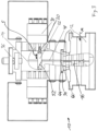
- the punching/perforating machine 10 shown schematically has a punching tool 12 and a control block 14.
- the control block 14 is connected to a pressure bar 36, i.e. it is inserted and centered in a control block guide groove 42 provided on the pressure bar 36.
- the pressure bar 36 is moved up and down in the stroke direction H by a drive unit 18.
- the corresponding punching tool 12 is located under the control block 14, the grid for the perforating needles 16 of which is identical to that of the control block 14.
- the punching tool 18 has a needle holder 34 which is inserted in a needle holder guide groove 44 in the control block 14.
- the lower part of the punching tool 12 with the dies is centered by means of a centering pin (not shown in detail). This lower part of the punching tool 12 is also placed in tool guide grooves 46.
- the needle holder 34 forms together with the needle guide, which is firmly connected to the punching tool 12, a unit, namely the punching tool 12.
- spacer plate 60 On the needle holder 34 there is a spacer plate 60, which on the one hand makes it easier to dismantle the punching tool 12 and on the other hand enables the use of other standard tools with the same tool profile but a different pitch.
- the open spacer plate 60 which is provided with grid holes (see Figures 1 to 4 ), by a closed variant without grid holes (see Fig. 5 ) replaced.
- the perforating needles 16 are arranged in a predetermined grid in the longitudinal direction L, which is perpendicular to the plane of representation of Fig. 1
- the perforating needles 16 can be individually activated or deactivated for each perforation stroke H.
- This individual control is implemented by providing a control device 30 which is in communication with a storage device 40 in which the geometric data of the perforation pattern to be created on a material web M fed to the punching tool 12 are stored.
- the control device 30 is in communication with a valve device 26, wherein the valve device 26 has valve units, each of which is individually in communication with piston-cylinder units arranged on the control block 14.
- the piston-cylinder units are designed as double-acting piston-cylinder units, with a cylinder 24, a piston 21 and a piston rod 20.
- a first pressure chamber 28 and a second pressure chamber 32 In each piston-cylinder unit there is a first pressure chamber 28 and a second pressure chamber 32.
- Each piston rod 20 is connected in its free end area to a locking slide 22, which can be moved from an activation position (extended state) and a deactivation position (retracted state) can be displaced in the sliding direction S transversely to the stroke direction H when the piston-cylinder unit is pressurized accordingly.
- a first pressure accumulator 28.1 and a second pressure accumulator 32.1 are present, which communicate with the valve device 26.
- the first pressure chamber 28 provides a pressure P1
- the second pressure chamber 32 provides a pressure P2 that is greater than the pressure P1.
- Each perforating needle 16 is assigned a locking slide 22 with an associated controllable piston-cylinder unit.
- the locking slide 22 is spaced apart from the upper head end of the perforating needle 16.
- an extension profile 48 is provided in the control block 14 in a corresponding guide, the underside of the extension profile 48 resting on the head of the associated perforating needle 16 and the upper front side of the extension profile 48 being arranged at the same height as the underside of the locking slide 22.
- the locking slide 22 has in its free end area a contour 52 which runs inclined against the stroke direction H, which ensures that if the extension profile 48 or the perforating needle 16 has an upward projection, the extension profile 48 is pushed downwards and is not sheared off or damaged. This ensures permanently reliable functionality.
- the first pressure chamber 28 and the second pressure chamber 32 are individually controlled via the valve device 26 and the control device 30, taking into account the stored perforation pattern data, as follows.
- the first pressure chamber 28 is permanently pressurized with the pressure P1 via the first pressure accumulator 28.1, i.e. under the effect of the pressure P1, the locking slide 22 is in the retracted position, so that when the perforation stroke H is carried out, the associated perforating needle 16 does not carry out any perforation.
- the control device 30 causes, via the valve device 26, that the second pressure chamber 32 is subjected to the pressure P2 via the second pressure accumulator 32.1, which is greater than the permanently present pressure P1 in the first pressure chamber 28, so that the locking slide 22 extends and, when the perforation stroke H is carried out, the associated perforating needle 16 in conjunction with the extension profile 48 carries out a perforation stroke H and creates a perforation on the material web M.
- the control block 14 thus has piston-cylinder units that are individually controlled and subject to a permanent first pressure P1, which virtually forms an air spring in the return stroke, wherein for each perforating needle 16 to be controlled in the punching tool 12, a piston rod 20 is assigned to the corresponding piston-cylinder unit, which is activated, i.e. extended, by being subjected to the pressure P2.
- a Fig. 1 An embodiment not shown in detail is used, in which a housing 38 is used which has four independently operating piston-cylinder units with piston rods 20. These piston-cylinder units are arranged offset from one another in the stroke direction H and in the longitudinal direction L within the housing 38, with the housings 38 being present on both sides of the control block 14. This results in a narrow structure.
- the connection to the locking slide 22 is made at the head of each piston rod 20 using a positive but loose connection. This connection allows play in both the axial and vertical directions. This counteracts possible damage to the extension profile 48 when the locking slide 22 is extended and retracted and improves functionality overall.
- the extension profile 48 is arranged between the head of the individual perforating needles 16 and the locking slide 22.
- the extension profile 48 consists, for example, of a hardened round material with a stepped diameter, which rests loosely on the head of the perforating needle 16.
- the stepped outer diameter prevents movement of the vertical built-in extension profile 48 in the control block 14 when installing or removing the tool.
- the extension profile 48 is held in a fixed, defined position above the needle head by this shoulder.
- these mechanical extension profiles 48 are inserted in different lengths in the control block 14 and assigned to the locking slides 22 accordingly.
- the individual piston-cylinder units are available as special cylinders on both sides of the control block 14 and are individually controlled by control valves 26.
- These special cylinders are arranged within the machine, for example in housings 38 with four piston-cylinder units each, in order to protect them from damage or access.
- These housings 38 contain the complete electronic and pneumatic control (valve islands, pressure regulators, pressure monitoring, etc.).
- These housings 38 are connected to the valve device 26 with their individually assigned control valves by means of a specially designed coupling system.
- the control valves of the valve device 26 can also be flexibly mounted on corresponding transport frames in order to use them on different punching machines. This means that you are not dependent on just one work area.
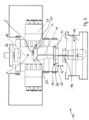
- the Fig. 2 shows a situation in which the locking slide 22 is extended before the perforation stroke is carried out.
- the Fig. 3 shows the situation with the locking slide 22 extended after the perforation stroke has been carried out.
- the Fig. 4 shows a locking slide 22 in retracted position after the perforation stroke has been carried out and the Fig. 5 shows the situation with the locking slide 22 extended, whereby a spacer plate 60 without holes is inserted before the perforation stroke is carried out, which means that during a perforation stroke all perforating needles 16 carry out a perforation.
- the guidance of the perforating needles 16 is in this case (see Fig. 5 ) laterally offset to the guide when using a spacer plate (60) with a hole pattern.
- the Fig. 6 finally shows the detail according to Fig. 2 with additionally shown first pressure accumulator 28.1 and the valve device 26 controlled by the control device 30.
Landscapes
- Engineering & Computer Science (AREA)
- Mechanical Engineering (AREA)
- Life Sciences & Earth Sciences (AREA)
- Forests & Forestry (AREA)
- Perforating, Stamping-Out Or Severing By Means Other Than Cutting (AREA)
- Punching Or Piercing (AREA)
Claims (17)
- Machine de poinçonnage/perforation (10) destinée à générer un motif de poinçonnage/perforation dans une unité/bande de matériau (M) acheminée, comportantun outil de poinçonnage (12), comportant plusieurs poinçons/aiguilles de perforation (16) disposés dans une grille prédéfinie dans une direction longitudinale (L), lesquels peuvent être déplacés par le biais d'une barre de pression (36) qui est en liaison fonctionnelle, par le biais d'un dispositif de commande (30), avec un groupe d'entraînement (18) pour produire une course de poinçonnage/perforation (H) transversalement à la direction longitudinale (L),un bloc de commande (14) destiné à commander/activer/désactiver les poinçons/aiguilles de perforation (16) au moyen du dispositif de commande (30) lors de l'opération de poinçonnage/perforation,l'outil de poinçonnage (12) et/ou le bloc de commande (14) étant réalisé(s) respectivement sous forme de module séparé qui est disposé à l'intérieur de la machine de poinçonnage/perforation (10) respectivement de manière à pouvoir être fixé de façon amovible séparément en tant qu'unité,caractérisée par les caractéristiques suivantes :un dispositif de mémorisation (40) dans lequel sont stockées les données pour la géométrie du motif de poinçonnage/perforation,un dispositif de commande (30) qui est en liaison de communication avec le dispositif de mémorisation (40),un bloc de commande (14) qui présente des unités piston-cylindre dont les mouvements pendant la course de poinçonnage/perforation peuvent être commandés individuellement par le biais du dispositif de commande (30) et qui sont associées individuellement à chaque poinçon/à chaque aiguille de perforation (16),un coulisseau de blocage (22) qui est raccordé respectivement à une tige de piston (20) correspondante de l'unité piston-cylindre, le coulisseau de blocage (22) pouvant coulisser dans une position d'activation ou de désactivation par le mouvement de la tige de piston (20),- le coulisseau de blocage, dans la position d'activation, agit directement ou indirectement sur le poinçon/l'aiguille de perforation (16) lors de l'exécution de la course (H),- le coulisseau de blocage, dans la position de désactivation, n'exerce aucune action sur le poinçon/l'aiguille de perforation (16),- de sorte que, dans la position d'activation du coulisseau de blocage (22), celui-ci agisse sur le poinçon/l'aiguille de perforation (16) lors du mouvement de course (H) et qu'une perforation soit effectuée et que, dans la position de désactivation du coulisseau de blocage, aucun poinçonnage/aucune perforation de l'unité/de la bande de matériau (M) ne soit provoquée, etcaractérisée en ce quele bloc de commande (14) présente des évidements de guidage disposés dans une grille pouvant être prédéfinie dans la direction longitudinale (L), laquelle grille correspond à la grille du poinçon/de l'aiguille de perforation (16), évidements de guidage dans lesquels sont présents des profilés de prolongement (48) montés de manière mobile longitudinalement dans la direction de course (H), profilés dont la longueur correspond à la distance entre le côté inférieur du coulisseau de blocage respectif et la tête du poinçon ou de l'aiguille de perforation (16) associé(e).
- Machine de poinçonnage/perforation selon la revendication 1,
caractérisée en ce que
l'outil de poinçonnage (12) et/ou le bloc de commande (14) sont disposés de manière rétractable/extensible dans la direction longitudinale (L) dans des rainures de guidage (42, 44, 46) présentes à l'intérieur de la machine de poinçonnage. - Machine de poinçonnage/perforation selon la revendication 2,
caractérisée en ce que
les rainures de guidage (42, 44, 46) sont réalisées de telle sorte que des unités d'adaptation supplémentaires peuvent être introduites afin de permettre le montage avec complémentarité de formes de différentes géométries d'outils de poinçonnage (12) ou de blocs de commande (14). - Machine de poinçonnage/perforation selon la revendication 1,
caractérisée en ce que
l'unité piston-cylindre est réalisée sous forme d'unité piston-cylindre à double action comportant une première chambre de pression (28) et une deuxième chambre de pression (32), la première chambre de pression (28) étant soumise en permanence, par le biais du dispositif de commande (30), à une première pression (P1) dont l'effet est que le coulisseau de blocage (22) se trouve ou est maintenu dans la position de désactivation et, lors de la réalisation d'un poinçonnage ou d'une perforation, l'unité de commande (30) soumet, en cas d'activation, la deuxième chambre de pression (32) à une deuxième pression (P2) qui est supérieure à la première pression (P1), de sorte que le coulisseau de blocage (22) sorte dans la position d'activation et ainsi, lors du mouvement de course (H), ce mouvement est transmis au poinçon associé/à l'aiguille de perforation associée, de sorte qu'un poinçonnage ou une perforation de l'unité/de la bande de matériau (M) soit réalisé(e). - Machine de poinçonnage/perforation selon la revendication 4,
caractérisée en ce que
le coulisseau de blocage (22) est raccordé respectivement à la tige de piston (20) correspondante de l'unité piston-cylindre avec complémentarité de formes avec jeu axial et radial. - Machine de poinçonnage/perforation selon l'une ou plusieurs des revendications précédentes,
caractérisée en ce que
le bloc de commande présente des boîtiers (38) pouvant être commandés individuellement par le dispositif de commande (30), lesquels présentent plusieurs unités piston-cylindre pouvant être commandées individuellement disposées de manière décalée dans la direction longitudinale (L) et dans la direction de course (H). - Machine de poinçonnage/perforation selon la revendication 6,
caractérisée en ce que
les unités piston-cylindre disposées à l'intérieur du boîtier (38) correspondent, dans la direction longitudinale (L), à une dimension de décalage de 0,5 fois, 1 fois et 2 fois la dimension de grille (R) de l'agencement de poinçons/d'aiguilles de perforation à l'intérieur de l'outil de poinçonnage (12). - Machine de poinçonnage/perforation selon l'une ou plusieurs des revendications 1 à 7,
caractérisée en ce
qu'une tôle d'espacement (60) est disposée par le dessus sur un porte-aiguilles (34) de l'outil de poinçonnage (12), laquelle tôle d'espacement soit présente des évidements congruents correspondant à la dimension de grille du poinçon/de l'aiguille de perforation (16) de la même dimension de grille soit est réalisée sous forme de tôle fermée. - Machine de poinçonnage/perforation selon l'une ou plusieurs des revendications 1 à 8,
caractérisée en ce
qu'un dispositif à soupapes (26) est présent, lequel est commandé par le dispositif de commande (30) et est en liaison de communication avec les unités piston-cylindre du bloc de commande (14). - Machine de poinçonnage/perforation selon l'une ou plusieurs des revendications 1 à 9,
caractérisée en ce que
le coulisseau de blocage (22) présente, dans sa région d'extrémité libre, un contour (52) incliné par rapport à la direction de course (H), de telle sorte que lors de la sortie du coulisseau de blocage (22), un profil de prolongement (48) éventuellement en saillie ou un poinçon/une aiguille de perforation (16) en saillie soit poussé(e) vers le bas dans la direction de course (H). - Machine de poinçonnage/perforation selon l'une ou plusieurs des revendications 1 à 10,
caractérisée en ce
qu'une unité laser de projection est présente, laquelle, en fonction des données stockées dans le dispositif de mémorisation relatives au contour du matériau à traiter ou à perforer, reproduit ces contours sur un tablier d'alimentation de la machine, de sorte qu'un alignement exact du matériau soit rendu possible et que les données de position alors acquises par le laser de projection soient acheminées au dispositif de commande (30). - Machine de poinçonnage/perforation selon l'une ou plusieurs des revendications 1 à 11,
caractérisée en ce que
le profil de prolongement (48) mobile longitudinalement présente un contour périphérique extérieur étagé et l'évidement de guidage associé présente un contour conjugué correspondant. - Machine de poinçonnage/perforation selon l'une ou plusieurs des revendications 1 à 12,
caractérisée en ce que
le boîtier (38) comportant plusieurs unités piston-cylindre est réalisé pour être autonome en termes de commande, régulation de pression et surveillance de pression ou similaire. - Machine de poinçonnage/perforation selon l'une ou plusieurs des revendications 1 à 13,
caractérisée en ce que
le dispositif à soupapes est réalisé de manière à pouvoir être raccordé séparément par rapport à la machine de poinçonnage/perforation. - Machine de poinçonnage/perforation selon l'une ou plusieurs des revendications 1 à 14,
caractérisée en ce que
le boîtier (38) présente quatre unités piston-cylindre et le bloc de commande (14)/l'outil de poinçonnage (12) présente quatre évidements de grille disposés de manière décalée en forme de grille dans la direction longitudinale (L) et dans la direction transversale pour le profilé de prolongement (48) ou le poinçon/les aiguilles de perforation (16). - Machine de poinçonnage/perforation selon l'une ou plusieurs des revendications 1 à 15,
caractérisée en ce que
la tôle d'espacement (60) est fixée sur le porte-aiguilles (34) du côté supérieur. - Machine de poinçonnage/perforation selon l'une ou plusieurs des revendications 1 à 16,
caractérisée en ce que
le dispositif à soupapes (26) est réalisé sous forme de système pneumatique ou hydraulique.
Priority Applications (3)
| Application Number | Priority Date | Filing Date | Title |
|---|---|---|---|
| MA54869A MA54869B1 (fr) | 2019-02-01 | 2020-01-31 | Machine à estamper/perforer |
| RS20250019A RS66366B1 (sr) | 2019-02-01 | 2020-01-31 | Mašina za probijanje/perforiranјe |
| HRP20241690TT HRP20241690T1 (hr) | 2019-02-01 | 2020-01-31 | Stroj za probijanje/perforiranje |
Applications Claiming Priority (2)
| Application Number | Priority Date | Filing Date | Title |
|---|---|---|---|
| DE202019000468.8U DE202019000468U1 (de) | 2019-02-01 | 2019-02-01 | Stanz-/Perforiermaschine |
| PCT/DE2020/000011 WO2020156606A2 (fr) | 2019-02-01 | 2020-01-31 | Machine à estamper/perforer |
Publications (3)
| Publication Number | Publication Date |
|---|---|
| EP3917735A2 EP3917735A2 (fr) | 2021-12-08 |
| EP3917735B1 true EP3917735B1 (fr) | 2024-10-30 |
| EP3917735C0 EP3917735C0 (fr) | 2024-10-30 |
Family
ID=65727993
Family Applications (1)
| Application Number | Title | Priority Date | Filing Date |
|---|---|---|---|
| EP20709467.3A Active EP3917735B1 (fr) | 2019-02-01 | 2020-01-31 | Machine à estamper/perforer |
Country Status (11)
| Country | Link |
|---|---|
| US (1) | US12121952B2 (fr) |
| EP (1) | EP3917735B1 (fr) |
| DE (2) | DE202019000468U1 (fr) |
| HR (1) | HRP20241690T1 (fr) |
| HU (1) | HUE070005T2 (fr) |
| MA (1) | MA54869B1 (fr) |
| MD (1) | MD3917735T2 (fr) |
| MX (1) | MX2021009286A (fr) |
| PL (1) | PL3917735T3 (fr) |
| RS (1) | RS66366B1 (fr) |
| WO (1) | WO2020156606A2 (fr) |
Families Citing this family (7)
| Publication number | Priority date | Publication date | Assignee | Title |
|---|---|---|---|---|
| DE202019001572U1 (de) | 2019-04-05 | 2019-06-03 | WISTA Werkzeugfertigungs-GmbH | Stanz-/Perforiermaschine und Bearbeitungsanlage mit einer derartigen Stanz-/Perforiermaschine |
| DE202019001573U1 (de) | 2019-04-05 | 2019-06-03 | WISTA Werkzeugfertigungs-GmbH | Stanz-/Perforiermaschine |
| DE102019124366A1 (de) * | 2019-09-11 | 2021-03-11 | Trumpf Werkzeugmaschinen Gmbh + Co. Kg | Rüstvorrichtung sowie Verfahren zum Rüsten eines Werkzeuges zum Stanzen oder Umformen von plattenförmigen Materialien |
| CN114474215B (zh) * | 2022-01-24 | 2024-08-09 | 湖南兴达科技有限公司 | 分段打孔式吸音材料一体式成型机床 |
| CN114633300A (zh) * | 2022-04-23 | 2022-06-17 | 深圳市永霖科技有限公司 | 一种打孔机 |
| DE102023124672A1 (de) | 2023-09-13 | 2025-03-13 | WISTA Werkzeugfertigungs-GmbH | Perforationsmaschine und Verfahren zur Erzeugung eines perforierten Materialabschnitts |
| CN118023397B (zh) * | 2024-04-11 | 2024-06-07 | 溧阳市力士汽车配件制造有限公司 | 一种汽车车门内板冲孔模具 |
Family Cites Families (22)
| Publication number | Priority date | Publication date | Assignee | Title |
|---|---|---|---|---|
| US4481533A (en) * | 1981-11-27 | 1984-11-06 | Lenkeit Industries, Inc. | Method and apparatus for successively positioning sheets of material with precision for punching aligning holes in the sheets enabling the sheets to be used in the manufacture of composite circuit boards |
| JPS59102298U (ja) * | 1982-12-27 | 1984-07-10 | 株式会社小松製作所 | プレス機械のスライド停止位置制御装置 |
| DE3339503C2 (de) | 1983-10-31 | 1985-09-05 | Dietz NC-Werkzeugsysteme, 8374 Viechtach | Stanzmaschine und Werkzeugsatz für Stanzmaschinen |
| US4947719A (en) * | 1987-09-01 | 1990-08-14 | S. B. Whistler & Sons, Inc. | Punch and die system |
| JPH02124295A (ja) * | 1988-10-28 | 1990-05-11 | Ushio Kk | 多軸穿孔装置 |
| NL8902274A (nl) * | 1989-09-12 | 1991-04-02 | Brouwer & Co Machine | Ponsmachine. |
| JPH07108425B2 (ja) * | 1990-03-23 | 1995-11-22 | 株式会社小松製作所 | パンチプレス |
| JPH0813387B2 (ja) | 1990-11-08 | 1996-02-14 | 株式会社三協マニテック | パンチング板打抜き加工装置 |
| EP0605802B1 (fr) * | 1992-12-07 | 1997-04-16 | Fuji Photo Film Co., Ltd. | Perforateur |
| JPH08323695A (ja) * | 1995-05-30 | 1996-12-10 | Metal Tec Kk | パンチング打抜き装置 |
| FI100648B (fi) * | 1995-12-14 | 1998-01-30 | Balaxman Oy | Levytyökeskus |
| US6006636A (en) * | 1997-07-24 | 1999-12-28 | International Business Machines Corporation | Programmable punch mechanism |
| DE19825842A1 (de) * | 1998-06-10 | 1999-12-16 | Schuler Pressen Gmbh & Co | Presse zur Herstellung variabler Bearbeitungsmuster |
| DE19855578C1 (de) * | 1998-12-02 | 2000-09-21 | Groz Beckert Kg | Stanzeinrichtung mit wechselbaren Stempeln |
| DE19929163C1 (de) * | 1999-06-25 | 2001-01-18 | Feintool Internat Holding Ag L | Vorrichtung zum Feinschneiden von Werkstücken aus einem Blech |
| TW559576B (en) * | 2002-03-20 | 2003-11-01 | Hon Hai Prec Ind Co Ltd | Electric-control progressing tool |
| DE10225512C1 (de) * | 2002-06-10 | 2003-07-17 | Duerkopp Adler Ag | Knopfloch-Nähmaschine |
| US8087333B2 (en) * | 2002-12-17 | 2012-01-03 | Ones Co., Ltd. | Method for press punching a hole in sheet metal and press die |
| DE202005010990U1 (de) | 2005-07-11 | 2005-09-22 | Großmann, Hans, Dipl.-Ing.(FH) | Vorrichtung zum Stanzen und/oder Umformen von Werkstücken |
| DE102014105266B4 (de) | 2014-04-14 | 2018-11-15 | Ring Besitz GmbH & Co. KG | Stanze |
| DE202017103498U1 (de) | 2017-06-12 | 2017-07-06 | Ring Maschinenbau GmbH | Perforiermaschine |
| DE202019001573U1 (de) * | 2019-04-05 | 2019-06-03 | WISTA Werkzeugfertigungs-GmbH | Stanz-/Perforiermaschine |
-
2019
- 2019-02-01 DE DE202019000468.8U patent/DE202019000468U1/de active Active
-
2020
- 2020-01-31 MX MX2021009286A patent/MX2021009286A/es unknown
- 2020-01-31 PL PL20709467.3T patent/PL3917735T3/pl unknown
- 2020-01-31 DE DE112020000652.2T patent/DE112020000652A5/de not_active Withdrawn
- 2020-01-31 MA MA54869A patent/MA54869B1/fr unknown
- 2020-01-31 MD MDE20211170T patent/MD3917735T2/ro unknown
- 2020-01-31 WO PCT/DE2020/000011 patent/WO2020156606A2/fr not_active Ceased
- 2020-01-31 EP EP20709467.3A patent/EP3917735B1/fr active Active
- 2020-01-31 RS RS20250019A patent/RS66366B1/sr unknown
- 2020-01-31 US US17/425,996 patent/US12121952B2/en active Active
- 2020-01-31 HU HUE20709467A patent/HUE070005T2/hu unknown
- 2020-01-31 HR HRP20241690TT patent/HRP20241690T1/hr unknown
Also Published As
| Publication number | Publication date |
|---|---|
| PL3917735T3 (pl) | 2025-03-17 |
| WO2020156606A2 (fr) | 2020-08-06 |
| US20240009726A1 (en) | 2024-01-11 |
| MD3917735T2 (ro) | 2025-02-28 |
| EP3917735A2 (fr) | 2021-12-08 |
| MX2021009286A (es) | 2021-11-12 |
| HRP20241690T1 (hr) | 2025-02-28 |
| US12121952B2 (en) | 2024-10-22 |
| DE112020000652A5 (de) | 2021-12-09 |
| EP3917735C0 (fr) | 2024-10-30 |
| MA54869B1 (fr) | 2024-12-31 |
| HUE070005T2 (hu) | 2025-04-28 |
| DE202019000468U1 (de) | 2019-02-22 |
| MA54869A (fr) | 2022-05-11 |
| WO2020156606A3 (fr) | 2020-10-01 |
| RS66366B1 (sr) | 2025-01-31 |
Similar Documents
| Publication | Publication Date | Title |
|---|---|---|
| EP3917735B1 (fr) | Machine à estamper/perforer | |
| DE3739029C2 (de) | Stanz- bzw. Nibbelverfahren und Vorrichtung hierfür | |
| EP2081707B1 (fr) | Outil et machine-outil pour l'usinage de pièces en forme de plaque et en particulier de tôles | |
| EP2036629A1 (fr) | Procédé et dispositif de coupe fine et de formage d'une pièce à usiner | |
| EP0418779A1 (fr) | Méthode pour manufacture de pièces d'oeuvre par découpage, en particulier dans un outil à contre découpage à précision | |
| DE2738344A1 (de) | Werkzeugmaschine, insbesondere stanzmaschine | |
| DE69228770T2 (de) | Index-Vorschubsystem | |
| EP3650213B1 (fr) | Presse à comprimés et procédé de fabrication d'un comprimé | |
| DE3339503C2 (de) | Stanzmaschine und Werkzeugsatz für Stanzmaschinen | |
| EP3946853B1 (fr) | Machine pour la perforation et l'emboutissage avec un cadre four la fixation du materiel a travailler | |
| DE2535817C3 (de) | Klemmeinrichtung an einer Revolverstanze | |
| DE68904062T2 (de) | Ziehpresse. | |
| DE3423543A1 (de) | Presse und verfahren zur herstellung derselben | |
| DE10359943A1 (de) | Programmierbare Vorrichtung sowie Verfahren zur Karosserieteil-Befestigung | |
| DE2637085C3 (de) | Vorrichtung zum Ausstoßen des Stanzabfalles oder Stanzteils mittels Druckluft | |
| EP3946854B1 (fr) | Dispositif pour le poinçonnage et la perforation | |
| DE3135266C2 (de) | Schneidpresse zum Herausschneiden oder -trennen von Teilen aus einer Werkstücktafel | |
| EP0585576B1 (fr) | Machine à poinçonner | |
| DE69210210T2 (de) | Revolverstanzmaschine | |
| DE1232917B (de) | Stanzvorrichtung zum Fertigen von genauen Blechteilen durch repassierendes Nachschneiden | |
| DE102006001389A1 (de) | Umformwerkzeug für eine Stanzmaschine | |
| DE2556466C2 (de) | Vorrichtung für das Feinstanzen mit festem Stempel | |
| DE8905741U1 (de) | Bearbeitungsvorrichtung zum Einsetzen in eine Presse | |
| DE202009008413U1 (de) | Werkzeugsystem für eine Umformpresse | |
| DE68912771T2 (de) | Verfahren zum hochpräzisionsschneiden mit stempel und gesenk. |
Legal Events
| Date | Code | Title | Description |
|---|---|---|---|
| REG | Reference to a national code |
Ref country code: HR Ref legal event code: TUEP Ref document number: P20241690T Country of ref document: HR |
|
| STAA | Information on the status of an ep patent application or granted ep patent |
Free format text: STATUS: UNKNOWN |
|
| STAA | Information on the status of an ep patent application or granted ep patent |
Free format text: STATUS: THE INTERNATIONAL PUBLICATION HAS BEEN MADE |
|
| PUAI | Public reference made under article 153(3) epc to a published international application that has entered the european phase |
Free format text: ORIGINAL CODE: 0009012 |
|
| STAA | Information on the status of an ep patent application or granted ep patent |
Free format text: STATUS: REQUEST FOR EXAMINATION WAS MADE |
|
| 17P | Request for examination filed |
Effective date: 20210827 |
|
| AK | Designated contracting states |
Kind code of ref document: A2 Designated state(s): AL AT BE BG CH CY CZ DE DK EE ES FI FR GB GR HR HU IE IS IT LI LT LU LV MC MK MT NL NO PL PT RO RS SE SI SK SM TR |
|
| RAV | Requested validation state of the european patent: fee paid |
Extension state: TN Effective date: 20210827 Extension state: MD Effective date: 20210827 Extension state: MA Effective date: 20210827 |
|
| RAX | Requested extension states of the european patent have changed |
Extension state: BA Payment date: 20210827 |
|
| RAP3 | Party data changed (applicant data changed or rights of an application transferred) |
Owner name: WISTA WERKZEUGFERTIGUNGS- GMBH |
|
| GRAP | Despatch of communication of intention to grant a patent |
Free format text: ORIGINAL CODE: EPIDOSNIGR1 |
|
| STAA | Information on the status of an ep patent application or granted ep patent |
Free format text: STATUS: GRANT OF PATENT IS INTENDED |
|
| INTG | Intention to grant announced |
Effective date: 20240307 |
|
| GRAS | Grant fee paid |
Free format text: ORIGINAL CODE: EPIDOSNIGR3 |
|
| GRAJ | Information related to disapproval of communication of intention to grant by the applicant or resumption of examination proceedings by the epo deleted |
Free format text: ORIGINAL CODE: EPIDOSDIGR1 |
|
| GRAL | Information related to payment of fee for publishing/printing deleted |
Free format text: ORIGINAL CODE: EPIDOSDIGR3 |
|
| STAA | Information on the status of an ep patent application or granted ep patent |
Free format text: STATUS: REQUEST FOR EXAMINATION WAS MADE |
|
| INTC | Intention to grant announced (deleted) | ||
| GRAP | Despatch of communication of intention to grant a patent |
Free format text: ORIGINAL CODE: EPIDOSNIGR1 |
|
| STAA | Information on the status of an ep patent application or granted ep patent |
Free format text: STATUS: GRANT OF PATENT IS INTENDED |
|
| GRAA | (expected) grant |
Free format text: ORIGINAL CODE: 0009210 |
|
| STAA | Information on the status of an ep patent application or granted ep patent |
Free format text: STATUS: THE PATENT HAS BEEN GRANTED |
|
| INTG | Intention to grant announced |
Effective date: 20240829 |
|
| AK | Designated contracting states |
Kind code of ref document: B1 Designated state(s): AL AT BE BG CH CY CZ DE DK EE ES FI FR GB GR HR HU IE IS IT LI LT LU LV MC MK MT NL NO PL PT RO RS SE SI SK SM TR |
|
| REG | Reference to a national code |
Ref country code: GB Ref legal event code: FG4D Free format text: NOT ENGLISH Ref country code: TN Ref legal event code: VAGR Ref document number: TN/P/2024/000425 Country of ref document: TN |
|
| REG | Reference to a national code |
Ref country code: CH Ref legal event code: EP |
|
| REG | Reference to a national code |
Ref country code: IE Ref legal event code: FG4D Free format text: LANGUAGE OF EP DOCUMENT: GERMAN |
|
| REG | Reference to a national code |
Ref country code: DE Ref legal event code: R096 Ref document number: 502020009617 Country of ref document: DE |
|
| U01 | Request for unitary effect filed |
Effective date: 20241120 |
|
| REG | Reference to a national code |
Ref country code: MA Ref legal event code: VAGR Ref document number: 54869 Country of ref document: MA Kind code of ref document: B1 |
|
| U07 | Unitary effect registered |
Designated state(s): AT BE BG DE DK EE FI FR IT LT LU LV MT NL PT RO SE SI Effective date: 20241127 |
|
| U20 | Renewal fee for the european patent with unitary effect paid |
Year of fee payment: 6 Effective date: 20250109 |
|
| REG | Reference to a national code |
Ref country code: HR Ref legal event code: ODRP Ref document number: P20241690T Country of ref document: HR Payment date: 20250122 Year of fee payment: 6 |
|
| REG | Reference to a national code |
Ref country code: SK Ref legal event code: T3 Ref document number: E 45725 Country of ref document: SK |
|
| REG | Reference to a national code |
Ref country code: HR Ref legal event code: T1PR Ref document number: P20241690 Country of ref document: HR Ref country code: MD Ref legal event code: VAGR Ref document number: 3917735 Country of ref document: MD Date of ref document: 20250228 Kind code of ref document: T2 |
|
| PG25 | Lapsed in a contracting state [announced via postgrant information from national office to epo] |
Ref country code: IS Free format text: LAPSE BECAUSE OF FAILURE TO SUBMIT A TRANSLATION OF THE DESCRIPTION OR TO PAY THE FEE WITHIN THE PRESCRIBED TIME-LIMIT Effective date: 20250228 |
|
| PG25 | Lapsed in a contracting state [announced via postgrant information from national office to epo] |
Ref country code: ES Free format text: LAPSE BECAUSE OF FAILURE TO SUBMIT A TRANSLATION OF THE DESCRIPTION OR TO PAY THE FEE WITHIN THE PRESCRIBED TIME-LIMIT Effective date: 20241030 |
|
| PG25 | Lapsed in a contracting state [announced via postgrant information from national office to epo] |
Ref country code: NO Free format text: LAPSE BECAUSE OF FAILURE TO SUBMIT A TRANSLATION OF THE DESCRIPTION OR TO PAY THE FEE WITHIN THE PRESCRIBED TIME-LIMIT Effective date: 20250130 |
|
| PG25 | Lapsed in a contracting state [announced via postgrant information from national office to epo] |
Ref country code: GR Free format text: LAPSE BECAUSE OF FAILURE TO SUBMIT A TRANSLATION OF THE DESCRIPTION OR TO PAY THE FEE WITHIN THE PRESCRIBED TIME-LIMIT Effective date: 20250131 |
|
| PGFP | Annual fee paid to national office [announced via postgrant information from national office to epo] |
Ref country code: CH Payment date: 20250201 Year of fee payment: 6 |
|
| PGFP | Annual fee paid to national office [announced via postgrant information from national office to epo] |
Ref country code: PL Payment date: 20250123 Year of fee payment: 6 Ref country code: CZ Payment date: 20250117 Year of fee payment: 6 |
|
| PGFP | Annual fee paid to national office [announced via postgrant information from national office to epo] |
Ref country code: SK Payment date: 20250121 Year of fee payment: 6 |
|
| REG | Reference to a national code |
Ref country code: HU Ref legal event code: AG4A Ref document number: E070005 Country of ref document: HU |
|
| PGFP | Annual fee paid to national office [announced via postgrant information from national office to epo] |
Ref country code: AL Payment date: 20250128 Year of fee payment: 6 |
|
| VSFP | Annual fee paid to validation state [announced via postgrant information from national office to epo] |
Ref country code: MD Payment date: 20250110 Year of fee payment: 6 |
|
| PG25 | Lapsed in a contracting state [announced via postgrant information from national office to epo] |
Ref country code: SM Free format text: LAPSE BECAUSE OF FAILURE TO SUBMIT A TRANSLATION OF THE DESCRIPTION OR TO PAY THE FEE WITHIN THE PRESCRIBED TIME-LIMIT Effective date: 20241030 |
|
| PLBI | Opposition filed |
Free format text: ORIGINAL CODE: 0009260 |
|
| PLAX | Notice of opposition and request to file observation + time limit sent |
Free format text: ORIGINAL CODE: EPIDOSNOBS2 |
|
| 26 | Opposition filed |
Opponent name: RING MASCHINENBAU GMBH Effective date: 20250724 |
|
| PG25 | Lapsed in a contracting state [announced via postgrant information from national office to epo] |
Ref country code: MC Free format text: LAPSE BECAUSE OF FAILURE TO SUBMIT A TRANSLATION OF THE DESCRIPTION OR TO PAY THE FEE WITHIN THE PRESCRIBED TIME-LIMIT Effective date: 20241030 |
|
| GBPC | Gb: european patent ceased through non-payment of renewal fee |
Effective date: 20250131 |
|
| PG25 | Lapsed in a contracting state [announced via postgrant information from national office to epo] |
Ref country code: GB Free format text: LAPSE BECAUSE OF NON-PAYMENT OF DUE FEES Effective date: 20250131 |
|
| PGFP | Annual fee paid to national office [announced via postgrant information from national office to epo] |
Ref country code: MK Payment date: 20250117 Year of fee payment: 6 |
|
| VSFP | Annual fee paid to validation state [announced via postgrant information from national office to epo] |
Ref country code: MA Payment date: 20250127 Year of fee payment: 6 |
|
| PLBB | Reply of patent proprietor to notice(s) of opposition received |
Free format text: ORIGINAL CODE: EPIDOSNOBS3 |
|
| PG25 | Lapsed in a contracting state [announced via postgrant information from national office to epo] |
Ref country code: IE Free format text: LAPSE BECAUSE OF NON-PAYMENT OF DUE FEES Effective date: 20250131 |
|
| REG | Reference to a national code |
Ref country code: CH Ref legal event code: U11 Free format text: ST27 STATUS EVENT CODE: U-0-0-U10-U11 (AS PROVIDED BY THE NATIONAL OFFICE) Effective date: 20260201 |
|
| PGFP | Annual fee paid to national office [announced via postgrant information from national office to epo] |
Ref country code: HU Payment date: 20260129 Year of fee payment: 7 |
|
| REG | Reference to a national code |
Ref country code: HR Ref legal event code: ODRP Ref document number: P20241690 Country of ref document: HR Payment date: 20260122 Year of fee payment: 7 |
|
| U20 | Renewal fee for the european patent with unitary effect paid |
Year of fee payment: 7 Effective date: 20260126 |
|
| PGFP | Annual fee paid to national office [announced via postgrant information from national office to epo] |
Ref country code: HR Payment date: 20260122 Year of fee payment: 7 |
|
| VSFP | Annual fee paid to validation state [announced via postgrant information from national office to epo] |
Ref country code: MD Payment date: 20260109 Year of fee payment: 7 |
|
| VSFP | Annual fee paid to validation state [announced via postgrant information from national office to epo] |
Ref country code: MA Payment date: 20260123 Year of fee payment: 7 |
|
| PGFP | Annual fee paid to national office [announced via postgrant information from national office to epo] |
Ref country code: RS Payment date: 20260121 Year of fee payment: 7 |