EP3919101B1 - Spritzenkappe, spritzenanordnung und vorgefüllte spritze - Google Patents
Spritzenkappe, spritzenanordnung und vorgefüllte spritze Download PDFInfo
- Publication number
- EP3919101B1 EP3919101B1 EP19921067.5A EP19921067A EP3919101B1 EP 3919101 B1 EP3919101 B1 EP 3919101B1 EP 19921067 A EP19921067 A EP 19921067A EP 3919101 B1 EP3919101 B1 EP 3919101B1
- Authority
- EP
- European Patent Office
- Prior art keywords
- section
- syringe
- distal end
- cap
- tubular
- Prior art date
- Legal status (The legal status is an assumption and is not a legal conclusion. Google has not performed a legal analysis and makes no representation as to the accuracy of the status listed.)
- Active
Links
Images


Classifications
-
- A—HUMAN NECESSITIES
- A61—MEDICAL OR VETERINARY SCIENCE; HYGIENE
- A61M—DEVICES FOR INTRODUCING MEDIA INTO, OR ONTO, THE BODY; DEVICES FOR TRANSDUCING BODY MEDIA OR FOR TAKING MEDIA FROM THE BODY; DEVICES FOR PRODUCING OR ENDING SLEEP OR STUPOR
- A61M5/00—Devices for bringing media into the body in a subcutaneous, intra-vascular or intramuscular way; Accessories therefor, e.g. filling or cleaning devices, arm-rests
- A61M5/178—Syringes
- A61M5/31—Details
- A61M5/32—Needles; Details of needles pertaining to their connection with syringe or hub; Accessories for bringing the needle into, or holding the needle on, the body; Devices for protection of needles
- A61M5/3202—Devices for protection of the needle before use, e.g. caps
-
- A—HUMAN NECESSITIES
- A61—MEDICAL OR VETERINARY SCIENCE; HYGIENE
- A61M—DEVICES FOR INTRODUCING MEDIA INTO, OR ONTO, THE BODY; DEVICES FOR TRANSDUCING BODY MEDIA OR FOR TAKING MEDIA FROM THE BODY; DEVICES FOR PRODUCING OR ENDING SLEEP OR STUPOR
- A61M5/00—Devices for bringing media into the body in a subcutaneous, intra-vascular or intramuscular way; Accessories therefor, e.g. filling or cleaning devices, arm-rests
- A61M5/178—Syringes
- A61M5/28—Syringe ampoules or carpules, i.e. ampoules or carpules provided with a needle
-
- A—HUMAN NECESSITIES
- A61—MEDICAL OR VETERINARY SCIENCE; HYGIENE
- A61M—DEVICES FOR INTRODUCING MEDIA INTO, OR ONTO, THE BODY; DEVICES FOR TRANSDUCING BODY MEDIA OR FOR TAKING MEDIA FROM THE BODY; DEVICES FOR PRODUCING OR ENDING SLEEP OR STUPOR
- A61M5/00—Devices for bringing media into the body in a subcutaneous, intra-vascular or intramuscular way; Accessories therefor, e.g. filling or cleaning devices, arm-rests
- A61M5/178—Syringes
- A61M5/31—Details
- A61M5/3129—Syringe barrels
- A61M5/3134—Syringe barrels characterised by constructional features of the distal end, i.e. end closest to the tip of the needle cannula
-
- A—HUMAN NECESSITIES
- A61—MEDICAL OR VETERINARY SCIENCE; HYGIENE
- A61M—DEVICES FOR INTRODUCING MEDIA INTO, OR ONTO, THE BODY; DEVICES FOR TRANSDUCING BODY MEDIA OR FOR TAKING MEDIA FROM THE BODY; DEVICES FOR PRODUCING OR ENDING SLEEP OR STUPOR
- A61M5/00—Devices for bringing media into the body in a subcutaneous, intra-vascular or intramuscular way; Accessories therefor, e.g. filling or cleaning devices, arm-rests
- A61M5/178—Syringes
- A61M5/31—Details
- A61M2005/3103—Leak prevention means for distal end of syringes, i.e. syringe end for mounting a needle
- A61M2005/3104—Caps for syringes without needle
-
- A—HUMAN NECESSITIES
- A61—MEDICAL OR VETERINARY SCIENCE; HYGIENE
- A61M—DEVICES FOR INTRODUCING MEDIA INTO, OR ONTO, THE BODY; DEVICES FOR TRANSDUCING BODY MEDIA OR FOR TAKING MEDIA FROM THE BODY; DEVICES FOR PRODUCING OR ENDING SLEEP OR STUPOR
- A61M5/00—Devices for bringing media into the body in a subcutaneous, intra-vascular or intramuscular way; Accessories therefor, e.g. filling or cleaning devices, arm-rests
- A61M5/178—Syringes
- A61M5/31—Details
- A61M2005/3103—Leak prevention means for distal end of syringes, i.e. syringe end for mounting a needle
- A61M2005/3106—Plugs for syringes without needle
-
- A—HUMAN NECESSITIES
- A61—MEDICAL OR VETERINARY SCIENCE; HYGIENE
- A61M—DEVICES FOR INTRODUCING MEDIA INTO, OR ONTO, THE BODY; DEVICES FOR TRANSDUCING BODY MEDIA OR FOR TAKING MEDIA FROM THE BODY; DEVICES FOR PRODUCING OR ENDING SLEEP OR STUPOR
- A61M39/00—Tubes, tube connectors, tube couplings, valves, access sites or the like, specially adapted for medical use
- A61M39/20—Closure caps or plugs for connectors or open ends of tubes
-
- A—HUMAN NECESSITIES
- A61—MEDICAL OR VETERINARY SCIENCE; HYGIENE
- A61M—DEVICES FOR INTRODUCING MEDIA INTO, OR ONTO, THE BODY; DEVICES FOR TRANSDUCING BODY MEDIA OR FOR TAKING MEDIA FROM THE BODY; DEVICES FOR PRODUCING OR ENDING SLEEP OR STUPOR
- A61M5/00—Devices for bringing media into the body in a subcutaneous, intra-vascular or intramuscular way; Accessories therefor, e.g. filling or cleaning devices, arm-rests
- A61M5/50—Devices for bringing media into the body in a subcutaneous, intra-vascular or intramuscular way; Accessories therefor, e.g. filling or cleaning devices, arm-rests having means for preventing re-use, or for indicating if defective, used, tampered with or unsterile
- A61M5/5086—Devices for bringing media into the body in a subcutaneous, intra-vascular or intramuscular way; Accessories therefor, e.g. filling or cleaning devices, arm-rests having means for preventing re-use, or for indicating if defective, used, tampered with or unsterile for indicating if defective, used, tampered with or unsterile
Definitions
- the present invention relates to a syringe cap, a syringe assembly, and a pre-filled syringe, in which the syringe cap is detachably attachable to a syringe body including: a body section capable of internally accommodating a drug; and a nozzle section protruding in a distal end direction from a distal end section of the body section and having a drug discharge port at a distal end.
- WO 2018/061948 A discloses a syringe cap including a cap body and a tubular cover member covering the cap body.
- the cap body has a mounting section that is mountable to a nozzle section of a syringe body, and a viewing section located on a distal end side from the mounting section.
- the cover member includes a substantially opaque first tubular section and a substantially transparent second tubular section extending in the distal end direction from an opening at a distal end of the first tubular section.
- the cap body is at a first position where the viewing section is located in the first tube section in an unopened state of the syringe cap. At this time, the viewing section is substantially invisible.
- the cap body is displaced from the first position to a second position where the viewing section protrudes in the distal end direction from the distal end of the first tubular section, by being pushed in the distal end direction by the nozzle section. That is, the viewing section becomes substantially visible. This makes it possible to discriminate between an unopened state and an opened state of the syringe cap.
- Figs. 38 to 40B of WO 2018/061948 A describes a configuration in which a tapered section inclined outward in a proximal end direction is provided at a portion on the distal end side from the first tubular section on an outer peripheral surface of the second tubular section.
- An outer peripheral surface of the tapered section is continuously inclined at a constant angle with respect to a center line of the cover member from a distal end to a proximal end of the tapered section.
- the present invention has been made in view of such problems, and an object is to provide a syringe cap, a syringe assembly, and a pre-filled syringe in which the syringe cap can be easily inserted into an insertion tube for conveyance, and an unopened state and an opened state of the syringe cap can be easily and reliably discriminated.
- a syringe cap detachably attachable to a syringe body including: a body section capable of internally accommodating a drug; and a nozzle section protruding in a distal end direction from a distal end section of the body section and having a drug discharge port at a distal end.
- the syringe cap includes a cap body and a cover member having a tubular shape and covering the cap body.
- the cap body has: a mounting section including a sealing section that liquid-tightly seals the drug discharge port, and being mountable to the nozzle section; and a viewing section located on a distal end side from the mounting section.
- the cover member includes: an engagement section provided on an inner peripheral surface of the cover member, and configured to engage with the cap body to prevent detachment of the cap body in a proximal end direction from the cover member; a first tubular section being substantially opaque, and having an opening at a distal end and a first space capable of internally housing the viewing section; and a second tubular section extending in a distal end direction from the opening of the first tubular section.
- the second tubular section includes: an annular peripheral wall section extending in a distal end direction from the opening of the first tubular section and having an outer diameter smaller than an outer diameter of the first tubular section; a distal end wall provided at a distal end of the annular peripheral wall section; a second space defined by the annular peripheral wall section, the distal end wall, and the opening of the first tubular section; and a tapered section protruding from an outer peripheral surface of the annular peripheral wall section toward a vicinity of an outer edge of the opening of the first tubular section so as to be inclined outward in a proximal end direction. At least the tapered section and the annular peripheral wall section of the second tubular section are substantially transparent.
- the cap body can displace, along a center axis of the cover member in the cover member, from a first position where the viewing section is located in the first space of the first tubular section to a second position where the viewing section protrudes in a distal end direction from the distal end of the first tubular section to be arranged in the second space.
- An outer peripheral section of the viewing section is substantially invisible when the cap body is at the first position, and the outer peripheral section of the viewing section becomes visible when the cap body is at the second position.
- the sealing section is capable of liquid-tightly sealing the nozzle section in a state where the cap body is located at the first position.
- the tapered section has, on an outer peripheral surface of the tapered section, a plurality of stepped sections continuously arranged along the center axis of the cover member, so as to gradually increase a protruding amount of the tapered section from an outer peripheral surface of the annular peripheral wall section toward a vicinity of the outer edge of the opening of the first tubular section.
- Another aspect of the present invention is a syringe assembly including: the syringe cap described above; and a syringe outer tube constituting the syringe body and being capable of accommodating a drug.
- Still another aspect of the present invention is a pre-filled syringe including: the syringe assembly described above; a drug filled in the syringe outer tube; and a gasket liquid-tightly slidable in the syringe outer tube in an axial direction.
- the cap body in an unopened state of the syringe cap, the cap body is at the first position where the viewing section is located in the first space of the substantially opaque first tubular section.
- the tapered section of the second tubular section has a plurality of stepped sections on the outer peripheral surface thereof.
- the cap body is displaced from the first position to the second position where the viewing section is located in the second space of the substantially transparent second tubular section. In this state, the user can visually recognize the viewing section. Therefore, even in a case where the syringe cap once removed from the syringe body is remounted to the syringe body, the user can discriminate between the unopened state and the opened state of the syringe cap.
- the plurality of stepped sections are continuously arranged along a center axis of the cover member such that a protruding amount of the tapered section gradually increases from the outer peripheral surface of the annular peripheral wall section toward a vicinity of the outer edge of the opening of the first tubular section. This can prevent the tapered section from being caught by the opening edge section of the insertion tube, when the syringe assembly (pre-filled syringe) with the syringe cap mounted to the syringe body is inserted into the insertion tube for conveyance. Therefore, the syringe assembly (pre-filled syringe) can be easily inserted into the insertion tube for conveyance.
- a preferred embodiment of a syringe cap, a syringe assembly, and a pre-filled syringe according to the present invention will be described with reference to the accompanying drawings.
- the left side in Fig. 1 is referred to as a "distal end”
- the right side is referred to as a "proximal end”.
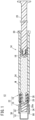
- a pre-filled syringe 12 includes a syringe body 14 and a syringe cap 10 (hereinafter, may be simply referred to as a "cap 10") detachably attachable to the syringe body 14.
- the syringe body 14 includes a syringe outer tube 16, a gasket 18 slidably inserted into the syringe outer tube 16, and a plunger 20 connected to the gasket 18.
- the syringe outer tube 16 and the cap 10 constitute a syringe assembly 22, and the pre-filled syringe 12 is assembled by inserting the gasket 18 connected with the plunger 20 in a state where the syringe outer tube 16 of the syringe assembly 22 is filled with a drug M.
- the syringe outer tube 16 has: a cylindrical body section 24 extending in an axial direction; a hollow nozzle section 26 projecting in the distal end direction from a distal end section of the body section 24; a syringe-side connecting section 28 provided on an outer peripheral side of the nozzle section 26; and a flange section 30 provided at a proximal end section of the body section 24.
- the body section 24, the nozzle section 26, the syringe-side connecting section 28, and the flange section 30 are integrally formed.
- the nozzle section 26 is a cylindrical member provided with a drug discharge port 26a at a distal end, and is configured as a luer connector.
- the syringe-side connecting section 28 is a lock adapter that projects from a distal end section of the body section 24 to a distal end side concentrically with the nozzle section 26, and has a female screw section 32 formed on an inner peripheral surface.
- an injection needle (not illustrated), and the like are detachably attachable.
- a constituent material of the syringe outer tube 16 is not particularly limited, but is preferably form by, for example: polyolefin such as polypropylene, polyurethane, polyethylene, cyclic polyolefin, or polymethylpentene 1; a resin material such as polyester, nylon, polycarbonate, polymethyl methacrylate (PMMA), polyetherimide (PEI), polyethersulfone, polyether ether ketone (PEEK), fluororesin, polyphenylene sulfide (PPS), or a polyacetal resin (POM); a metal material such as stainless steel; glass; or the like.
- polyolefin such as polypropylene, polyurethane, polyethylene, cyclic polyolefin, or polymethylpentene 1
- a resin material such as polyester, nylon, polycarbonate, polymethyl methacrylate (PMMA), polyetherimide (PEI), polyethersulfone, polyether ether ketone (PEEK), fluorores
- the gasket 18 is liquid-tightly slidable in the syringe outer tube 16 in an axial direction, and feeds the drug M filled in the syringe outer tube 16.
- a distal end of the plunger 20 is connected to the gasket 18.
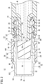
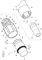
- the cap 10 includes a cap body 34 that closes the drug discharge port 26a of the nozzle section 26 in an unopened state, and a tubular cover member 36 that covers the cap body 34.
- Examples of a constituent material of the cap body 34 include rubber, a synthetic resin elastomer, and the like.
- the rubber include isoprene rubber, butyl rubber, latex rubber, and silicone rubber.
- the synthetic resin elastomer for example, a styrene elastomer, an olefin elastomer, or the like can be used.
- the cap body 34 includes a mounting tube section 38 (mounting section) and a viewing section 40 (distal end extending section) extending the distal end direction from a distal end of the mounting tube section 38.
- the mounting tube section 38 includes a sealing section 42 that is located at a distal end section of the mounting tube section 38 and is capable of liquid-tightly sealing the drug discharge port 26a, and a raised section 44 raised from the sealing section 42.
- the sealing section 42 seals the drug discharge port 26a by abutting on a distal end section of the nozzle section 26, specifically, a distal end surface of the nozzle section 26 or a side peripheral surface of the distal end section of the nozzle section 26.
- the liquid-tightly sealing the drug discharge port 26a means that the drug M does not leak to the outside of the cap body 34. Therefore, even when the sealing section 42 abuts only on the side peripheral surface of the distal end section of the nozzle section 26, the sealing section 42 liquid-tightly seals the drug discharge port 26a.
- annular abutting protruding section 46 (abutting section) capable of abutting on a distal end section of the nozzle section 26 is provided.
- a mounted state unopened state in which the cap body 34 is mounted to the nozzle section 26
- the abutting protruding section 46 is in contact with an outer peripheral surface of the nozzle section 26 in a compressed and deformed state.
- an annular bulging section 48 is provided on an outer peripheral surface of the mounting tube section 38.
- the bulging section 48 is a section having a maximum outer diameter of the cap body 34.
- the bulging section 48 is compressed and deformed by being sandwiched between the nozzle section 26 and a tubular connecting section 54 described later, in the mounted state of the cap body 34.
- the viewing section 40 is formed in a cylindrical shape.
- the viewing section 40 may be colored in a color that is relatively easily recognized by the user, such as red, for example.
- the coloring of the viewing section 40 may be performed by applying paint to an outer surface of the viewing section 40, or the cap body 34 may be made of rubber or synthetic resin colored in advance.
- the cover member 36 includes a cap cover 50 and a distal end cover member 52.
- the cap cover 50 is formed in a cylindrical shape and is made of a resin material having no transparency (substantially opaque resin material).
- the cap cover 50 has: the tubular connecting section 54 that is located at a proximal end section thereof and is detachably attachable to a syringe side by screwing; a tube body section 56 extending in the distal end direction from a distal end of the tubular connecting section 54; and an opening 58 provided at a distal end of the tube body section 56 to expose the cap body 34 from the cap cover 50.
- a plurality of engagement claw sections 60 (engagement sections, engagement protrusions) extending radially inward are provided.
- the plurality of engagement claw sections 60 are intermittently provided along a circumferential direction of the tubular connecting section 54. Specifically, the plurality of engagement claw sections 60 are provided at equal intervals along the circumferential direction of the tubular connecting section 54.
- An inner diameter of a hole formed by projecting ends (inner end sections) of the plurality of engagement claw sections 60 is smaller than an outer diameter of a proximal end section of the mounting tube section 38 of the cap body 34.
- a surface directed in the distal end direction is a flat surface extending in a direction orthogonal to a center axis Ax of the cover member 36, and can be in contact with a proximal end surface of the cap body 34.
- the engagement claw section 60 has an inclined surface inclined inward in the distal end direction on the proximal end side of the engagement claw section 60.
- a proximal end of the tube body section 56 is provided with an insertion regulating section 62 that can abut on a distal end of the syringe-side connecting section 28.
- the insertion regulating section 62 regulates an insertion length of the tubular connecting section 54 between the syringe-side connecting section 28 and the nozzle section 26, by abutting on the distal end of the syringe-side connecting section 28.
- the tubular connecting section 54 is a cylindrical member provided concentrically with the cap cover 50, and has an outer peripheral surface provided with a male screw section 64 that can be screwed with the female screw section 32.
- the tube body section 56 is formed in a size that allows a user to easily pick with fingers.
- an annular recess 66 is formed at a proximal end section of an outer peripheral surface of the tube body section 56.
- an annular recess 66 is formed at a proximal end section of an outer peripheral surface of the tube body section 56.
- two through holes 68 are formed on a bottom surface of the annular recess 66.
- the two through holes 68 are opposed to each other.
- an anti-slip section 70 functioning as a slip stopper for the user's fingers is formed.
- the anti-slip section 70 is formed by providing a plurality of ribs 72 extending in an axial direction at equal intervals in a circumferential direction.
- six ribs 72 are provided in the circumferential direction of the tube body section 56. As described above, by setting the number of ribs 72 to six, moldability (injection molding accuracy) of the cap cover 50 is improved.
- a locking protruding section 74 to lock the distal end cover member 52 protrudes radially inward.
- Two locking protruding sections 74 are provided so as to be opposed to each other.
- the distal end cover member 52 is formed to have a substantially U-shaped longitudinal cross section, and is to cover the cap body 34 such that the user operating the cap 10 together with the cap cover 50 cannot touch the cap body 34. That is, the distal end cover member 52 has a contact prevention function.
- the distal end cover member 52 also functions as a detachment prevention section that prevents detachment of the cap body 34 from the opening 58 of the cap cover 50.
- the distal end cover member 52 has: an annular section 76 having a proximal end section fitted to the tube body section 56 of the cap cover 50 so as to project toward a distal end side from the opening 58 of the cap cover 50; and a distal end wall 78 provided at a distal end section of the annular section 76.
- the annular section 76 includes an annular peripheral wall section 80 on the distal end side and a tubular extending inner tube section 82 extending in the proximal end direction from the annular peripheral wall section 80.
- An inner diameter of the annular section 76 is constant from the distal end to the proximal end, and is larger than an outer diameter of the viewing section 40.
- an inner diameter of the distal end cover member 52 is substantially uniform from a distal end of the annular peripheral wall section 80 to a proximal end of the extending inner tube section 82.
- the proximal end of the extending inner tube section 82 is in contact with the distal end of the tubular connecting section 54.
- an annular locking claw 84 to be in contact with the locking protruding section 74 of the cap cover 50 is provided.
- An outer diameter of the locking claw 84 is larger than a separation interval of the locking protruding section 74.
- a tapered section 86 protruding so as to be inclined outward in the proximal end direction toward the distal end of the tube body section 56 (in a vicinity of an outer edge of the opening 58 of the tube body section 56).
- the tapered section 86 annularly extends along a circumferential direction of the annular peripheral wall section 80.
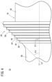
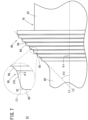
- a plurality of (for example, seven) stepped sections 88 are arranged continuously along the center axis Ax of the cover member 36 such that a protruding amount of the tapered section 86 gradually increases from the outer peripheral surface of the annular peripheral wall section 80 toward the distal end of the tube body section 56.
- Each stepped section 88 annularly extends along the circumferential direction of the annular peripheral wall section 80.
- Each of the stepped sections 88 has: a first surface 90; a bent section 92 located at an outer edge of the first surface 90; a second surface 94 extending in the proximal end direction from the bent section 92; and an inclined surface 96 extending while being inclined outward (radially outward) from a proximal end of the second surface 94 and continuing to an inner edge of the first surface 90 of the stepped section 88 adjacent on the proximal end side.
- An angle ⁇ 1 formed by the first surface 90 and a parallel straight line L1 parallel to the center axis Ax of the cover member 36 is larger than a taper angle ⁇ 2 formed by the parallel straight line L1 and a virtual straight line L2 passing through a distal end and a proximal end of the tapered section 86.
- the second surface 94 extends parallel to the center axis Ax of the cover member 36.
- the angle ⁇ 1 is preferably set to 60° or more and 90° or less. In the present embodiment, the angle ⁇ 1 is set to 90 °.
- the taper angle ⁇ 2 is preferably set to 35° or more and 55° or less.
- the inclined surface 96 extends along the virtual straight line L2. In other words, the inclined surface 96 extends so as to overlap with the virtual straight line L2. Note that the inclined surface 96 may extend parallel to the virtual straight line L2.
- the bent section 92 has a curved surface protruding outward.
- a size, a number, a position, and a shape of the stepped section 88 can be appropriately set.
- the stepped section 88 does not need to have the inclined surface 96. That is, the stepped section 88 may be formed such that a proximal end of the second surface 94 is continuous to an inner edge of the first surface 90 of the stepped section 88 adjacent on the proximal end side of the adjacent stepped section 88.
- a distal end curved surface 98 protruding outward is formed between an outer edge of the distal end wall 78 and the annular peripheral wall section 80 (boundary section).
- a curvature radius of the distal end curved surface 98 is preferably set to 0.3 mm or more and 1.0 mm or less.
- the distal end cover member 52 is integrally molded using a resin material having transparency.
- the transparency of the distal end cover member 52 is set higher than the transparency of the cap cover 50. This allows the user to visually recognize the inside of the distal end cover member 52 from the outside of the cap 10 more clearly than the inside of the cap cover 50.
- the distal end cover member 52 is colorless, but may be colored.
- such a cover member 36 includes the engagement claw section 60, a first tubular section 100, and a second tubular section 102.
- the engagement claw section 60 is provided on an inner peripheral surface of the cover member 36, and prevents detachment of the cap body 34 in the proximal end direction from the cover member 36, by engaging with the cap body 34.
- the first tubular section 100 has the opening 58 at a distal end and a first space S1 that can internally accommodate the viewing section 40.
- the first tubular section 100 is substantially opaque.
- the first tubular section 100 includes the extending inner tube section 82 forming an inner peripheral section of the first tubular section 100, and the tube body section 56 forming an outer peripheral section of the first tubular section 100.
- the second tubular section 102 is substantially transparent as a whole, and extends in the distal end direction from the opening 58 of the first tubular section 100.
- the second tubular section 102 includes the annular peripheral wall section 80, the distal end wall 78, a second space S2, and the tapered section 86.
- the annular peripheral wall section 80 extends in the distal end direction from the opening 58 of the first tubular section 100, and has an outer diameter smaller than an outer diameter of the first tubular section 100.
- the distal end wall 78 is provided at the distal end of the annular peripheral wall section 80.
- the second space S2 is defined by the annular peripheral wall section 80, the distal end wall 78, and the opening 58 of the first tubular section 100.
- the tapered section 86 protrudes so as to be inclined outward in the proximal end direction from the outer peripheral surface of the annular peripheral wall section 80 toward a vicinity of the outer edge of the opening 58 of the first tubular section 100.
- the cap body 34 in an unopened state of the cap 10, the cap body 34 is at a first position where the viewing section 40 is located in the first space S1 of the first tubular section 100. Specifically, the distal end of the cap body 34 is located in the proximal end direction from the opening 58 of the tube body section 56, and inside the extending inner tube section 82 of the distal end cover member 52. As a result, the outer peripheral section of the viewing section 40 is hidden by the substantially opaque first tubular section (tube body section 56) and cannot be visually recognized from the outside. Further, the mounting tube section 38 is in a state of being mounted to the nozzle section 26, and the sealing section 42 of the mounting tube section 38 liquid-tightly seals the drug discharge port 26a of the nozzle section 26.
- the cover member 36 is pulled out from the syringe outer tube 16 in a state where screwing between the male screw section 64 and the female screw section 32 is released. This causes the engagement claw section 60 of the tubular connecting section 54 to come into contact with the proximal end surface of the cap body 34. Then, the cap body 34 is pushed in the distal end direction by the tubular connecting section 54, and the mounting tube section 38 is detached from the nozzle section 26. This leads to opening of the cap 10 (see Fig. 5A ).
- the distal end section of the nozzle section 26 of the syringe outer tube 16 is inserted into the tubular connecting section 54 from the opening 58 on the proximal end side of the tubular connecting section 54. This causes the distal end section of the nozzle section 26 to come into contact with the abutting protruding section 46 of the cap body 34.
- the cap body 34 at the first position is displaced in the distal end direction with respect to the cap cover 50 by being pushed by the nozzle section 26, and the viewing section 40 protrudes toward the distal end side from the opening 58 on the distal end side of the cap cover 50.
- the opened cap 10 is recapped (remounted) to the syringe outer tube 16.
- the cap body 34 is at the second position where the viewing section 40 is located in the second space S2 of the second tubular section 102 (on the distal end side from the opening 58 of the tube body section 56) (see Fig. 5B ). Therefore, the outer peripheral section of the viewing section 40 can be visually recognized from the outside via the transparent second tubular section 102 (distal end cover member 52).
- the cap 10, the syringe assembly 22, and the pre-filled syringe 12 according to the present embodiment have the following effects.
- the cap body 34 in an unopened state of the cap 10, the cap body 34 is at the first position where the viewing section 40 is located in the first space S1 of the substantially opaque first tubular section 100.
- the tapered section 86 of the second tubular section 102 has a plurality of stepped sections 88 on the outer peripheral surface thereof.
- the cap body 34 is displaced from the first position to the second position where the viewing section 40 is located in the second space S2 of the substantially transparent second tubular section 102. In this state, the user can visually recognize the viewing section 40. Therefore, even in a case where the cap 10 once removed from the syringe body 14 is remounted to the syringe body 14, the user can discriminate between the unopened state and the opened state of the cap 10.
- the plurality of stepped sections 88 are arranged continuously along the center axis Ax of the cover member 36 such that a protruding amount of the tapered section 86 gradually increases from the outer peripheral surface of the annular peripheral wall section 80 toward a vicinity of the outer edge of the opening 58 of the first tubular section 100.
- a protruding amount of the tapered section 86 gradually increases from the outer peripheral surface of the annular peripheral wall section 80 toward a vicinity of the outer edge of the opening 58 of the first tubular section 100.
- each of the plurality of stepped sections 88 has the first surface 90, the bent section 92 located at the outer edge of the first surface 90, and the second surface 94 extending in the proximal end direction from the bent section 92.
- the angle ⁇ 1 formed by the first surface 90 and the parallel straight line L1 parallel to the center axis Ax of the cover member 36 is larger than the taper angle ⁇ 2 formed by the parallel straight line L1 and the virtual straight line L2 passing through the distal end and the proximal end of the tapered section 86.
- the second surface 94 extends parallel to the center axis Ax.
- the viewing section 40 of the cap body 34 at the first position can be made further less visible when the user views the tapered section 86 from just beside in an unopened state of the cap 10.
- the taper angle ⁇ 2 is 35° or more and 55° or less.
- the syringe assembly 22 (pre-filled syringe 12) can be more easily inserted into the insertion tube 200 for conveyance.
- Each of the plurality of stepped sections 88 has: the inclined surface 96 extending while being inclined outward from the proximal end of the second surface 94 and continuing to the inner edge of the first surface 90 of the stepped section 88 adjacent on the proximal end side.
- the bent section 92 has a curved surface protruding outward.
- the second tubular section 102 is substantially transparent as a whole, and has the distal end curved surface 98 projecting outward between the outer edge of the distal end wall 78 and the annular peripheral wall section 80.
- a curvature radius of the distal end curved surface 98 is 0.3 mm or more and 1.0 mm or less.
- the entire second tubular section 102 is transparent, the user can easily visually recognize the viewing section 40 in a state where the cap 10 is remounted to the syringe body 14. In addition, it is possible to suppress a decrease in visibility of the viewing section 40 due to reflection of light on the distal end curved surface 98.
- the cover member 36 includes: the tube body section 56 constituting at least an outer peripheral section of the first tubular section 100 and being substantially opaque; and the cover member 36 having the second tubular section 102 and being substantially transparent.
- the configuration of the substantially opaque first tubular section 100 and the substantially transparent second tubular section 102 can be simplified.
- the distal end cover member 52 includes the extending inner tube section 82 that extends from the proximal end of the annular peripheral wall section 80 into the tube body section 56 and forms the inner peripheral section of the first tubular section 100.
- An inner diameter of the distal end cover member 52 is substantially uniform from the distal end of the annular peripheral wall section 80 to a proximal end of the extending inner tube section 82.
- the cap body 34 can be smoothly displaced from the first position to the second position.
- the cap 10, the syringe assembly 22, and the pre-filled syringe 12 according to the present invention are not limited to the above-described embodiment, and it is a matter of course that various configurations can be adopted without departing from the gist of the present invention.
- a second surface 110 of the tapered section 86 may be inclined outward (radially outward) from the bent section 92 in the proximal end direction.
- an angle ⁇ 1 first angle ⁇ 1
- an angle ⁇ 3 second angle ⁇ 3 formed by the second surface 110 and a parallel straight line L3 parallel to the center axis Ax of the cover member 36 is smaller than the taper angle ⁇ 2.
- first angle ⁇ 1, the taper angle ⁇ 2, and the second angle ⁇ 3 are set such that a relationship of ⁇ 3 ⁇ ⁇ 2 ⁇ ⁇ 1 is established.
- the first angle ⁇ 1 is preferably set to 60° or more and 90° or less.
- the taper angle ⁇ 2 is preferably set to 35° or more and 55° or less.
- the second angle ⁇ 3 is preferably set to 30° or less.
- each of the plurality of stepped sections 88 has the first surface 90, the bent section 92 located at the outer edge of the first surface 90, and the second surface 110 extending in the proximal end direction from the bent section 92.
- the first angle ⁇ 1 is larger than the taper angle ⁇ 2, and the second angle ⁇ 3 is smaller than the taper angle ⁇ 2.
- the viewing section 40 of the cap body 34 at the first position can be made further less visible when the user views the tapered section 86 from just beside in an unopened state of the cap 10.
- the present invention may be, for example, the pre-filled syringe 12 having no plunger 20.
- a pressing member that presses the gasket 18 in the distal end direction is separately mounted.
- the cap 10, the syringe assembly 22, or the pre-filled syringe 12 in which the abutting protruding section 46 is omitted from the cap body 34 may be adopted.
- the proximal end of the mounting tube section 38 functions as an abutting section that can abut on the distal end section of the nozzle section 26.
- the cap body 34 may be configured such that the viewing section 40 does not include the distal end of the cap body 34, and the distal end of the cap body 34 protrudes to the distal end side from the opening 58 of the cap cover 50, at the first position.
- the viewing section 40 of the cap body 34 is provided so as to be located in the tube body section 56 of the cap cover 50 when the cap body 34 is at the first position, and to protrude from the opening 58 of the cap cover 50 when the cap body 34 is at the second position.
- Examples of such a viewing section 40 include: a viewing section 40 formed by coloring an outer peripheral surface that is slightly on the proximal end side from the distal end of the cap body 34 in red or the like; a viewing section 40 formed by a colored member fitted so as to cover an outer peripheral section that is slightly on the proximal end side from the distal end of the distal end protruding section of the cap body 34; and the like. Even with such a configuration, the user can easily and reliably discriminate between the unopened state and the recapped state of the cap 10.
- a hole having such a size that a user's finger cannot be inserted may be formed in the distal end wall 78 of the distal end cover member 52.
- a hole having such a size that a user's finger cannot be inserted may be formed on the distal end wall 78.
- the cap 10 may be provided with a temporary fixing mechanism that performs temporary fixing to prevent movement of the cap body 34 from the first position to the second position in a state where the cap 10 is removed from the syringe body 14.
- a temporary fixing mechanism include a temporary fixing protrusion provided on an inner peripheral surface of the cap cover 50 and engaged with a part of the cap body 34 arranged at the first position. In this case, an engagement force between the temporary fixing protrusion and the cap body 34 is set to be releasable by pressing the mounting section (mounting tube section 38) of the cap body 34 with the nozzle section 26 of the syringe body 14.
- the cap body 34 is movable from the first position to the second position without the mounting section (mounting tube section 38) being pushed by the nozzle section 26. Therefore, in a case where the cap 10 removed from the syringe body 14 is remounted to the syringe body 14 in a state where the cap body 34 is arranged at the second position, displacement of the cap body 34 from the first position to the second position does not occur.
Landscapes
- Health & Medical Sciences (AREA)
- Vascular Medicine (AREA)
- Engineering & Computer Science (AREA)
- Anesthesiology (AREA)
- Biomedical Technology (AREA)
- Heart & Thoracic Surgery (AREA)
- Hematology (AREA)
- Life Sciences & Earth Sciences (AREA)
- Animal Behavior & Ethology (AREA)
- General Health & Medical Sciences (AREA)
- Public Health (AREA)
- Veterinary Medicine (AREA)
- Infusion, Injection, And Reservoir Apparatuses (AREA)
Claims (13)
- Spritzenkappe (10), die in der Lage ist, abnehmbar an einem Spritzenkörper (14) angebracht zu werden, umfassend: einen Körperabschnitt (24), der in der Lage ist, im Inneren ein Arzneimittel (M) aufzunehmen; und einen Düsenabschnitt (26), der in einer Richtung zu dem distalen Ende von einem distalen Endabschnitt des Körperabschnitts (24) hin hervorsteht und eine Arzneimittelabgabeöffnung (26a) an einem distalen Ende aufweist, wobei die Spritzenkappe (10) umfasst:einen Kappenkörper (34); undein Abdeckungselement (36), das eine röhrenförmige Gestalt aufweist und den Kappenkörper (34) abdeckt, wobeider Kappenkörper (34) umfasst:einen Befestigungsabschnitt (38), der einen Dichtungsabschnitt (42) umfasst, der die Arzneimittelabgabeöffnung (26a) flüssigkeitsdicht abdichtet, und der an dem Düsenabschnitt (26) befestigbar ist; undeinen Sichtabschnitt (40), der an einer distalen Endseite von dem Befestigungsabschnitt (38) angeordnet ist,das Abdeckungselement (36) umfasst:einen Eingriffsabschnitt (60), der an einer inneren Umfangsfläche des Abdeckungselements (36) vorgesehen ist und so konfiguriert ist, dass er mit dem Kappenkörper (34) in Eingriff kommt, um ein Lösen des Kappenkörpers (34) in einer Richtung zu dem proximalen Ende von dem Abdeckungselement (36) hin zu verhindern;einen ersten röhrenförmigen Abschnitt (100), der im Wesentlichen undurchsichtig ist und eine Öffnung (58) an einem distalen Ende und einen ersten Raum (S1) aufweist, der in der Lage ist, den Sichtabschnitt (40) in dem Inneren aufzunehmen; undeinen zweiten röhrenförmigen Abschnitt (102), der sich in einer Richtung zu dem distalen Ende von der Öffnung (58) des ersten röhrenförmigen Abschnitts (100) hin erstreckt,der zweite röhrenförmige Abschnitt (102) umfasst:einen ringförmigen Umfangswandabschnitt (80), der sich in einer Richtung zu dem distalen Ende von der Öffnung (58) des ersten röhrenförmigen Abschnitts (100) hin erstreckt und einen Außendurchmesser aufweist, der kleiner ist als ein Außendurchmesser des ersten röhrenförmigen Abschnitts (100);eine distale Endwand (78), die an einem distalen Ende des ringförmigen Umfangswandabschnitts (80) vorgesehen ist,einen zweiten Raum (S2), der durch den ringförmigen Umfangswandabschnitt (80), die distale Endwand (78) und die Öffnung (58) des ersten röhrenförmigen Abschnitts (100) definiert ist; undeinen sich verjüngenden Abschnitt (86), der von einer äußeren Umfangsfläche des ringförmigen Umfangswandabschnitts (80) in Richtung einer Umgebung einer Außenkante der Öffnung (58) des ersten röhrenförmigen Abschnitts (100) hin vorsteht, sodass er in einer Richtung zu einem proximalen Ende hin nach außen geneigt ist,mindestens der sich verjüngende Abschnitt (86) und der ringförmige Umfangswandabschnitt (80) des zweiten röhrenförmigen Abschnitts (102) im Wesentlichen transparent sind,der Kappenkörper (34) in der Lage ist, sich entlang einer Mittelachse (Ax) des Abdeckungselements (36) in dem Abdeckungselement (36) von einer ersten Position, in welcher der Sichtabschnitt (40) in dem ersten Raum (S1) des ersten röhrenförmigen Abschnitts (100) angeordnet ist, in eine zweite Position zu verschieben, in welcher der Sichtabschnitt (40) in einer Richtung zu dem distalen Ende von dem distalen Ende des ersten röhrenförmigen Abschnitts (100) hin vorsteht, um in dem zweiten Raum (S2) angeordnet zu werden,ein äußerer Umfangsabschnitt des Sichtabschnitts (40) im Wesentlichen unsichtbar ist, wenn sich der Kappenkörper (34) in der ersten Position befindet, und der äußere Umfangsabschnitt des Sichtabschnitts (40) sichtbar wird, wenn sich der Kappenkörper (34) in der zweiten Position befindet,der Dichtungsabschnitt (42) in der Lage ist, den Düsenabschnitt (26) in einem Zustand flüssigkeitsdicht abzudichten, in dem sich der Kappenkörper (34) in der ersten Position befindet, undin einem Zustand, in dem der Kappenkörper (34) in der ersten Position angeordnet ist, wenn der Befestigungsabschnitt (38) der von dem Spritzenkörper (14) entfernten Spritzenkappe (10) in die Nähe von dem Düsenabschnitt (26) des Spritzenkörpers (14) gebracht wird, wird der Befestigungsabschnitt (38) durch den Düsenabschnitt (26) des Spritzenkörpers (14) in eine Richtung zu dem distalen Ende geschoben, um den Kappenkörper (34) von der ersten Position in die zweite Position zu verschieben,dadurch gekennzeichnet, dassder sich verjüngende Abschnitt (86) an einer äußeren Umfangsfläche des sich verjüngenden Abschnitts (86) eine Mehrzahl von abgestuften Abschnitten (88) aufweist, die kontinuierlich entlang der Mittelachse (Ax) des Abdeckungselements (36) angeordnet sind, sodass ein hervorstehender Betrag des sich verjüngenden Abschnitts (86) von einer äußeren Umfangsfläche des ringförmigen Umfangswandabschnitts (80) in Richtung einer Nähe der Außenkante der Öffnung (58) des ersten röhrenförmigen Abschnitts (100) allmählich zunimmt.
- Spritzenkappe (10) nach Anspruch 1, wobeijeder von der Mehrzahl der gestuften Abschnitte (88) eine erste Oberfläche (90), einen gebogenen Abschnitt (92), der an einer Außenkante der ersten Oberfläche (90) angeordnet ist, und eine zweite Oberfläche (94) aufweist, die sich in einer Richtung zu dem proximalen Ende von dem gebogenen Abschnitt (92) erstreckt,ein erster Winkel (θ1), der durch die erste Oberfläche (90) und eine parallele gerade Linie (L1) parallel zur Mittelachse (Ax) des Abdeckungselements (36) gebildet wird, größer ist als ein Verjüngungswinkel (θ2), der durch die parallele gerade Linie (L1) und eine virtuelle gerade Linie (L2) gebildet wird, die durch ein distales Ende und ein proximales Ende des sich verjüngenden Abschnitts (86) verläuft, undein zweiter Winkel (θ3), der durch die zweite Oberfläche (94) und eine parallele gerade Linie (L3) parallel zu der Mittelachse (Ax) des Abdeckungselements (36) gebildet wird, kleiner ist als der Verjüngungswinkel (θ2).
- Spritzenkappe (10) nach Anspruch 1, wobeijeder von der Mehrzahl der gestuften Abschnitte (88) eine erste Oberfläche (90), einen gebogenen Abschnitt (92), der an einer Außenkante der ersten Oberfläche (90) angeordnet ist, und eine zweite Oberfläche (94) aufweist, die sich in einer Richtung zu dem proximalen Ende von dem gebogenen Abschnitt (92) erstreckt,ein Winkel (θ1), der durch die erste Oberfläche (90) und eine parallele gerade Linie (L1) parallel zu der Mittelachse (Ax) des Abdeckungselements (36) gebildet wird, größer ist als ein Verjüngungswinkel (θ2), der durch die parallele gerade Linie (L1) und eine virtuelle gerade Linie (L2) gebildet wird, die durch ein distales Ende und ein proximales Ende des sich verjüngenden Abschnitts (86) verläuft, und die zweite Oberfläche (94) sich parallel zu der Mittelachse (Ax) erstreckt.
- Spritzenkappe (10) nach Anspruch 2, wobei
der Verjüngungswinkel (θ2) 35° oder mehr und 55° oder weniger beträgt. - Spritzenkappe (10) nach Anspruch 4, wobeider erste Winkel (θ1) 60° oder mehr und 90° oder weniger beträgt, undder zweite Winkel (θ3) 30° oder weniger beträgt.
- Spritzenkappe (10) nach einem der Ansprüche 2 bis 5, wobei
jeder von der Mehrzahl der abgestuften Abschnitte (88) aufweist: eine geneigte Oberfläche (96), die sich, während sie geneigt ist, von einem proximalen Ende der zweiten Oberfläche (94) nach außen erstreckt und sich bis zu dem inneren Rand der ersten Oberfläche (90) eines abgestuften Abschnitts (88) fortsetzt, der an einer Seite des proximalen Endes angrenzt. - Spritzenkappe (10) nach einem der Ansprüche 2 bis 6, wobei
der gebogene Abschnitt (92) eine gekrümmte Oberfläche aufweist, die nach außen hervorsteht. - Spritzenkappe (10) nach einem der Ansprüche 2 bis 7, wobeider zweite röhrenförmige Abschnitt (102) als Ganzes im Wesentlichen transparent ist und eine gekrümmte Oberfläche (98) am distalen Ende aufweist, die zwischen einer Außenkante der distalen Endwand (78) und einem ringförmigen Umfangswandabschnitt (80) nach außen hervorsteht, undein Krümmungsradius der gekrümmten Oberfläche (98) des distalen Endes 0,3 mm oder mehr und 1,0 mm oder weniger beträgt.
- Spritzenkappe (10) nach einem der Ansprüche 1 bis 8, wobei
das Abdeckungselement (36) umfasst:einen Röhrenkörperabschnitt (56), der mindestens einen äußeren Umfangsabschnitt des ersten röhrenförmigen Abschnitts (100) bildet und im Wesentlichen undurchsichtig ist; undein Abdeckungselement (52) des distalen Endes, das den zweiten röhrenförmigen Abschnitt (102) aufweist und im Wesentlichen transparent ist. - Spritzenkappe (10) nach Anspruch 9, wobeidas Abdeckungselement (52) des distalen Endes einen sich erstreckenden inneren Röhrenabschnitt (82) aufweist, der sich von einem proximalen Ende des ringförmigen Umfangswandabschnitts (80) in den Röhrenkörperabschnitt (56) erstreckt und einen inneren Umfangsabschnitt des ersten röhrenförmigen Abschnitts (100) bildet, undein Innendurchmesser des Abdeckungselements (52) des distalen Endes von einem distalen Ende des ringförmigen Umfangswandabschnitts (80) zu einem proximalen Ende des sich erstreckenden inneren Röhrenabschnitts (82) im Wesentlichen gleichmäßig ist.
- Spritzenkappe (10) nach einem der Ansprüche 1 bis 10, wobeider Spritzenkörper (14) einen zylindrischen Verriegelungsadapter (28) umfasst, der eine röhrenförmige Gestalt aufweist, der einen Schraubabschnitt (32) mit Innengewinde an einer inneren Umfangsfläche des Verriegelungsadapters aufweist, und einen äußeren Umfangsabschnitt des Düsenabschnitts (26) abdeckt,der Befestigungsabschnitt (38) ein Befestigungsrohrabschnitt (38) ist, der eine röhrenförmige Gestalt aufweist und in der Lage ist, den Düsenabschnitt (26) aufzunehmen,der Befestigungsrohrabschnitt (38) aufweist:den Dichtungsabschnitt (42), der an einem distalen Endabschnitt des Befestigungsrohrabschnitts (38) angeordnet ist; undeinen Anschlagabschnitt (46), der an einem proximalen Endabschnitt des Befestigungsrohrabschnitts (38) angeordnet und in der Lage ist, an einem distalen Endabschnitt des Düsenabschnitts (26) anzuschlagen,das Abdeckungselement (36) einen röhrenförmigen Verbindungsabschnitt (54) aufweist, der sich in Richtung zu einem proximalen Ende von einem proximalen Ende des ersten röhrenförmigen Abschnitts (100) erstreckt und in der Lage ist, zwischen den Verriegelungsadapter (28) und den Düsenabschnitt (26) eingesetzt zu werden,der röhrenförmige Verbindungsabschnitt (54) einen Schraubabschnitt (64) mit Außengewinde aufweist, der in der Lage ist, mit dem Schraubabschnitt (32) mit Innengewinde des Verriegelungsadapters (28) an einem äußeren Umfangsabschnitt des röhrenförmigen Verbindungsabschnitts (54) verschraubt zu werden,in einem Zustand, in dem die Spritzenkappe (10) durch Verschrauben zwischen dem Schraubabschnitt (64) mit Außengewinde des röhrenförmigen Verbindungsabschnitts (54) und dem Schraubabschnitt (32) mit Innengewinde des Verriegelungsadapters (28) auf dem Spritzenkörper (14) befestigt ist und der Kappenkörper (34) in der ersten Position angeordnet ist, der Befestigungsrohrabschnitt (38) zwischen dem röhrenförmigen Verbindungsabschnitt (54) und dem Düsenabschnitt (26) eingesetzt ist und der Dichtungsabschnitt (42) die Arzneimittelabgabeöffnung (26a) flüssigkeitsdicht abdichtet, undwenn der Schraubabschnitt (64) mit Außengewinde des röhrenförmigen Verbindungsabschnitts (54) mit dem Schraubabschnitt (32) mit Innengewinde des Verriegelungsadapters (28) in einem Zustand verschraubt wird, in dem die Spritzenkappe (10) von dem Spritzenkörper (14) entfernt ist, wird der Kappenkörper (34) von der ersten Position in die zweite Position verschoben, indem der Anschlagabschnitt (46) des Kappenkörpers (34) durch den distalen Endabschnitt des Düsenabschnitts (26) gedrückt wird.
- Spritzenanordnung (22), umfassend:die Spritzenkappe (10) nach einem der Ansprüche 1 bis 11; undein äußeres Spritzenrohr (16), das den Spritzenkörper (14) bildet und in der Lage ist, ein Arzneimittel (M) aufzunehmen.
- Vorgefüllte Spritze (12), umfassend:
die Spritzenanordnung (22) nach Anspruch 12:ein Arzneimittel (M), das in das äußere Spritzenrohr (16) gefüllt ist; undeine Dichtung (18), die flüssigkeitsdicht in dem äußeren Spritzenrohr (16) in einer axialen Richtung verschiebbar ist.
Applications Claiming Priority (1)
| Application Number | Priority Date | Filing Date | Title |
|---|---|---|---|
| PCT/JP2019/012195 WO2020194397A1 (ja) | 2019-03-22 | 2019-03-22 | シリンジ用キャップ、シリンジ組立体及びプレフィルドシリンジ |
Publications (3)
| Publication Number | Publication Date |
|---|---|
| EP3919101A1 EP3919101A1 (de) | 2021-12-08 |
| EP3919101A4 EP3919101A4 (de) | 2022-03-09 |
| EP3919101B1 true EP3919101B1 (de) | 2025-02-12 |
Family
ID=72610388
Family Applications (1)
| Application Number | Title | Priority Date | Filing Date |
|---|---|---|---|
| EP19921067.5A Active EP3919101B1 (de) | 2019-03-22 | 2019-03-22 | Spritzenkappe, spritzenanordnung und vorgefüllte spritze |
Country Status (6)
| Country | Link |
|---|---|
| US (1) | US12397121B2 (de) |
| EP (1) | EP3919101B1 (de) |
| JP (1) | JP7241164B2 (de) |
| CN (1) | CN113573758B (de) |
| AU (1) | AU2019437468B2 (de) |
| WO (1) | WO2020194397A1 (de) |
Family Cites Families (9)
| Publication number | Priority date | Publication date | Assignee | Title |
|---|---|---|---|---|
| EP2826508A1 (de) * | 2013-07-18 | 2015-01-21 | Becton Dickinson France | Spitzenkappe und Injektionsvorrichtung mit distaler, durch eine Spitzenkappe abgedichteter Spitze |
| US9821123B2 (en) * | 2014-01-27 | 2017-11-21 | Ucb Biopharma Sprl | Auto-injector |
| WO2015186792A1 (ja) * | 2014-06-04 | 2015-12-10 | 大成化工株式会社 | シリンジキャップ、針付シリンジ、及びプレフィルドシリンジ製剤 |
| CN106659844B (zh) * | 2014-08-06 | 2020-04-24 | 泰尔茂株式会社 | 包装体及包装组装体 |
| US10369083B2 (en) * | 2014-12-02 | 2019-08-06 | Kpr U.S., Llc | Adapter assembly for enteral feeding and method of making |
| US20170232160A1 (en) * | 2016-02-16 | 2017-08-17 | Gabriel Cardwell | Incision syringe with disposable cartridge |
| JP6776341B2 (ja) | 2016-04-15 | 2020-10-28 | テルモ株式会社 | シリンジ用バレル及びその製造方法並びにプレフィルドシリンジ |
| CN108883232A (zh) * | 2016-04-25 | 2018-11-23 | 泰尔茂株式会社 | 用于预灌封注射器的注射器主体、注射器装置及预灌封注射器 |
| JP6889725B2 (ja) | 2016-09-30 | 2021-06-18 | テルモ株式会社 | キャップ、シリンジ組立体及びプレフィルドシリンジ |
-
2019
- 2019-03-22 EP EP19921067.5A patent/EP3919101B1/de active Active
- 2019-03-22 WO PCT/JP2019/012195 patent/WO2020194397A1/ja not_active Ceased
- 2019-03-22 JP JP2021508379A patent/JP7241164B2/ja active Active
- 2019-03-22 CN CN201980094169.9A patent/CN113573758B/zh active Active
- 2019-03-22 AU AU2019437468A patent/AU2019437468B2/en active Active
-
2021
- 2021-09-22 US US17/481,928 patent/US12397121B2/en active Active
Also Published As
| Publication number | Publication date |
|---|---|
| EP3919101A4 (de) | 2022-03-09 |
| US20220008660A1 (en) | 2022-01-13 |
| AU2019437468A1 (en) | 2021-10-07 |
| JPWO2020194397A1 (de) | 2020-10-01 |
| CN113573758B (zh) | 2023-03-24 |
| EP3919101A1 (de) | 2021-12-08 |
| WO2020194397A1 (ja) | 2020-10-01 |
| AU2019437468B2 (en) | 2022-12-15 |
| CN113573758A (zh) | 2021-10-29 |
| JP7241164B2 (ja) | 2023-03-16 |
| US12397121B2 (en) | 2025-08-26 |
Similar Documents
| Publication | Publication Date | Title |
|---|---|---|
| US11273264B2 (en) | Cap, syringe assembly, and prefilled syringe | |
| JP7241166B2 (ja) | シリンジ用キャップ、シリンジ組立体及びプレフィルドシリンジ | |
| US20190388626A1 (en) | Syringe assembly and prefilled syringe | |
| AU2023229546B2 (en) | Syringe cap, syringe assembly, and pre-filled syringe | |
| CN101980737A (zh) | 穿刺针组合体以及药液注入器具 | |
| US11660402B2 (en) | Syringe and prefilled syringe | |
| EP3919101B1 (de) | Spritzenkappe, spritzenanordnung und vorgefüllte spritze | |
| CN115397496B (zh) | 医用容器、用于安装到所述医用容器上的适配器以及包括所述医用容器的药物输送器械 | |
| EP3868429B1 (de) | Adapter für einen medizinischen behälter, medizinischer behälter mit besagtem adapter und verfahren zur herstellung des besagten adapters | |
| JP7322061B2 (ja) | シリンジ用キャップ、シリンジ組立体及びプレフィルドシリンジ | |
| US20230075695A1 (en) | Adaptor for Mounting onto a Medical Container, a Medical Container Comprising Said Adaptor, and a Method for Manufacturing Said Adaptor |
Legal Events
| Date | Code | Title | Description |
|---|---|---|---|
| STAA | Information on the status of an ep patent application or granted ep patent |
Free format text: STATUS: THE INTERNATIONAL PUBLICATION HAS BEEN MADE |
|
| PUAI | Public reference made under article 153(3) epc to a published international application that has entered the european phase |
Free format text: ORIGINAL CODE: 0009012 |
|
| STAA | Information on the status of an ep patent application or granted ep patent |
Free format text: STATUS: REQUEST FOR EXAMINATION WAS MADE |
|
| 17P | Request for examination filed |
Effective date: 20210903 |
|
| AK | Designated contracting states |
Kind code of ref document: A1 Designated state(s): AL AT BE BG CH CY CZ DE DK EE ES FI FR GB GR HR HU IE IS IT LI LT LU LV MC MK MT NL NO PL PT RO RS SE SI SK SM TR |
|
| A4 | Supplementary search report drawn up and despatched |
Effective date: 20220207 |
|
| RIC1 | Information provided on ipc code assigned before grant |
Ipc: A61M 39/20 20060101ALI20220201BHEP Ipc: A61M 5/50 20060101ALI20220201BHEP Ipc: A61M 5/28 20060101ALI20220201BHEP Ipc: A61M 5/31 20060101AFI20220201BHEP |
|
| DAV | Request for validation of the european patent (deleted) | ||
| DAX | Request for extension of the european patent (deleted) | ||
| STAA | Information on the status of an ep patent application or granted ep patent |
Free format text: STATUS: EXAMINATION IS IN PROGRESS |
|
| 17Q | First examination report despatched |
Effective date: 20220718 |
|
| GRAP | Despatch of communication of intention to grant a patent |
Free format text: ORIGINAL CODE: EPIDOSNIGR1 |
|
| STAA | Information on the status of an ep patent application or granted ep patent |
Free format text: STATUS: GRANT OF PATENT IS INTENDED |
|
| INTG | Intention to grant announced |
Effective date: 20241129 |
|
| GRAS | Grant fee paid |
Free format text: ORIGINAL CODE: EPIDOSNIGR3 |
|
| GRAA | (expected) grant |
Free format text: ORIGINAL CODE: 0009210 |
|
| STAA | Information on the status of an ep patent application or granted ep patent |
Free format text: STATUS: THE PATENT HAS BEEN GRANTED |
|
| AK | Designated contracting states |
Kind code of ref document: B1 Designated state(s): AL AT BE BG CH CY CZ DE DK EE ES FI FR GB GR HR HU IE IS IT LI LT LU LV MC MK MT NL NO PL PT RO RS SE SI SK SM TR |
|
| REG | Reference to a national code |
Ref country code: GB Ref legal event code: FG4D |
|
| REG | Reference to a national code |
Ref country code: CH Ref legal event code: EP |
|
| REG | Reference to a national code |
Ref country code: DE Ref legal event code: R096 Ref document number: 602019065974 Country of ref document: DE |
|
| REG | Reference to a national code |
Ref country code: IE Ref legal event code: FG4D |
|
| REG | Reference to a national code |
Ref country code: NL Ref legal event code: MP Effective date: 20250212 |
|
| PG25 | Lapsed in a contracting state [announced via postgrant information from national office to epo] |
Ref country code: RS Free format text: LAPSE BECAUSE OF FAILURE TO SUBMIT A TRANSLATION OF THE DESCRIPTION OR TO PAY THE FEE WITHIN THE PRESCRIBED TIME-LIMIT Effective date: 20250512 |
|
| PG25 | Lapsed in a contracting state [announced via postgrant information from national office to epo] |
Ref country code: FI Free format text: LAPSE BECAUSE OF FAILURE TO SUBMIT A TRANSLATION OF THE DESCRIPTION OR TO PAY THE FEE WITHIN THE PRESCRIBED TIME-LIMIT Effective date: 20250212 |
|
| PG25 | Lapsed in a contracting state [announced via postgrant information from national office to epo] |
Ref country code: PL Free format text: LAPSE BECAUSE OF FAILURE TO SUBMIT A TRANSLATION OF THE DESCRIPTION OR TO PAY THE FEE WITHIN THE PRESCRIBED TIME-LIMIT Effective date: 20250212 |
|
| PG25 | Lapsed in a contracting state [announced via postgrant information from national office to epo] |
Ref country code: ES Free format text: LAPSE BECAUSE OF FAILURE TO SUBMIT A TRANSLATION OF THE DESCRIPTION OR TO PAY THE FEE WITHIN THE PRESCRIBED TIME-LIMIT Effective date: 20250212 |
|
| REG | Reference to a national code |
Ref country code: LT Ref legal event code: MG9D |
|
| PG25 | Lapsed in a contracting state [announced via postgrant information from national office to epo] |
Ref country code: NO Free format text: LAPSE BECAUSE OF FAILURE TO SUBMIT A TRANSLATION OF THE DESCRIPTION OR TO PAY THE FEE WITHIN THE PRESCRIBED TIME-LIMIT Effective date: 20250512 Ref country code: IS Free format text: LAPSE BECAUSE OF FAILURE TO SUBMIT A TRANSLATION OF THE DESCRIPTION OR TO PAY THE FEE WITHIN THE PRESCRIBED TIME-LIMIT Effective date: 20250612 |
|
| PG25 | Lapsed in a contracting state [announced via postgrant information from national office to epo] |
Ref country code: NL Free format text: LAPSE BECAUSE OF FAILURE TO SUBMIT A TRANSLATION OF THE DESCRIPTION OR TO PAY THE FEE WITHIN THE PRESCRIBED TIME-LIMIT Effective date: 20250212 |
|
| PG25 | Lapsed in a contracting state [announced via postgrant information from national office to epo] |
Ref country code: HR Free format text: LAPSE BECAUSE OF FAILURE TO SUBMIT A TRANSLATION OF THE DESCRIPTION OR TO PAY THE FEE WITHIN THE PRESCRIBED TIME-LIMIT Effective date: 20250212 |
|
| PG25 | Lapsed in a contracting state [announced via postgrant information from national office to epo] |
Ref country code: PT Free format text: LAPSE BECAUSE OF FAILURE TO SUBMIT A TRANSLATION OF THE DESCRIPTION OR TO PAY THE FEE WITHIN THE PRESCRIBED TIME-LIMIT Effective date: 20250612 Ref country code: LV Free format text: LAPSE BECAUSE OF FAILURE TO SUBMIT A TRANSLATION OF THE DESCRIPTION OR TO PAY THE FEE WITHIN THE PRESCRIBED TIME-LIMIT Effective date: 20250212 |
|
| PG25 | Lapsed in a contracting state [announced via postgrant information from national office to epo] |
Ref country code: GR Free format text: LAPSE BECAUSE OF FAILURE TO SUBMIT A TRANSLATION OF THE DESCRIPTION OR TO PAY THE FEE WITHIN THE PRESCRIBED TIME-LIMIT Effective date: 20250513 Ref country code: BG Free format text: LAPSE BECAUSE OF FAILURE TO SUBMIT A TRANSLATION OF THE DESCRIPTION OR TO PAY THE FEE WITHIN THE PRESCRIBED TIME-LIMIT Effective date: 20250212 |
|
| REG | Reference to a national code |
Ref country code: AT Ref legal event code: MK05 Ref document number: 1765494 Country of ref document: AT Kind code of ref document: T Effective date: 20250212 |
|
| PG25 | Lapsed in a contracting state [announced via postgrant information from national office to epo] |
Ref country code: SE Free format text: LAPSE BECAUSE OF FAILURE TO SUBMIT A TRANSLATION OF THE DESCRIPTION OR TO PAY THE FEE WITHIN THE PRESCRIBED TIME-LIMIT Effective date: 20250212 |
|
| PG25 | Lapsed in a contracting state [announced via postgrant information from national office to epo] |
Ref country code: SM Free format text: LAPSE BECAUSE OF FAILURE TO SUBMIT A TRANSLATION OF THE DESCRIPTION OR TO PAY THE FEE WITHIN THE PRESCRIBED TIME-LIMIT Effective date: 20250212 |
|
| PG25 | Lapsed in a contracting state [announced via postgrant information from national office to epo] |
Ref country code: DK Free format text: LAPSE BECAUSE OF FAILURE TO SUBMIT A TRANSLATION OF THE DESCRIPTION OR TO PAY THE FEE WITHIN THE PRESCRIBED TIME-LIMIT Effective date: 20250212 |
|
| PG25 | Lapsed in a contracting state [announced via postgrant information from national office to epo] |
Ref country code: IT Free format text: LAPSE BECAUSE OF FAILURE TO SUBMIT A TRANSLATION OF THE DESCRIPTION OR TO PAY THE FEE WITHIN THE PRESCRIBED TIME-LIMIT Effective date: 20250212 |
|
| PG25 | Lapsed in a contracting state [announced via postgrant information from national office to epo] |
Ref country code: AT Free format text: LAPSE BECAUSE OF FAILURE TO SUBMIT A TRANSLATION OF THE DESCRIPTION OR TO PAY THE FEE WITHIN THE PRESCRIBED TIME-LIMIT Effective date: 20250212 |
|
| PG25 | Lapsed in a contracting state [announced via postgrant information from national office to epo] |
Ref country code: EE Free format text: LAPSE BECAUSE OF FAILURE TO SUBMIT A TRANSLATION OF THE DESCRIPTION OR TO PAY THE FEE WITHIN THE PRESCRIBED TIME-LIMIT Effective date: 20250212 Ref country code: CZ Free format text: LAPSE BECAUSE OF FAILURE TO SUBMIT A TRANSLATION OF THE DESCRIPTION OR TO PAY THE FEE WITHIN THE PRESCRIBED TIME-LIMIT Effective date: 20250212 |
|
| PG25 | Lapsed in a contracting state [announced via postgrant information from national office to epo] |
Ref country code: RO Free format text: LAPSE BECAUSE OF FAILURE TO SUBMIT A TRANSLATION OF THE DESCRIPTION OR TO PAY THE FEE WITHIN THE PRESCRIBED TIME-LIMIT Effective date: 20250212 |
|
| REG | Reference to a national code |
Ref country code: CH Ref legal event code: H13 Free format text: ST27 STATUS EVENT CODE: U-0-0-H10-H13 (AS PROVIDED BY THE NATIONAL OFFICE) Effective date: 20251023 |
|
| PG25 | Lapsed in a contracting state [announced via postgrant information from national office to epo] |
Ref country code: SK Free format text: LAPSE BECAUSE OF FAILURE TO SUBMIT A TRANSLATION OF THE DESCRIPTION OR TO PAY THE FEE WITHIN THE PRESCRIBED TIME-LIMIT Effective date: 20250212 |
|
| REG | Reference to a national code |
Ref country code: DE Ref legal event code: R097 Ref document number: 602019065974 Country of ref document: DE |
|
| PG25 | Lapsed in a contracting state [announced via postgrant information from national office to epo] |
Ref country code: LU Free format text: LAPSE BECAUSE OF NON-PAYMENT OF DUE FEES Effective date: 20250322 |
|
| REG | Reference to a national code |
Ref country code: BE Ref legal event code: MM Effective date: 20250331 |
|
| PLBE | No opposition filed within time limit |
Free format text: ORIGINAL CODE: 0009261 |
|
| STAA | Information on the status of an ep patent application or granted ep patent |
Free format text: STATUS: NO OPPOSITION FILED WITHIN TIME LIMIT |
|
| PG25 | Lapsed in a contracting state [announced via postgrant information from national office to epo] |
Ref country code: MC Free format text: LAPSE BECAUSE OF FAILURE TO SUBMIT A TRANSLATION OF THE DESCRIPTION OR TO PAY THE FEE WITHIN THE PRESCRIBED TIME-LIMIT Effective date: 20250212 |
|
| PG25 | Lapsed in a contracting state [announced via postgrant information from national office to epo] |
Ref country code: BE Free format text: LAPSE BECAUSE OF NON-PAYMENT OF DUE FEES Effective date: 20250331 |
|
| PG25 | Lapsed in a contracting state [announced via postgrant information from national office to epo] |
Ref country code: CH Free format text: LAPSE BECAUSE OF NON-PAYMENT OF DUE FEES Effective date: 20250331 |
|
| PG25 | Lapsed in a contracting state [announced via postgrant information from national office to epo] |
Ref country code: IE Free format text: LAPSE BECAUSE OF NON-PAYMENT OF DUE FEES Effective date: 20250322 |
|
| 26N | No opposition filed |
Effective date: 20251113 |
|
| PGFP | Annual fee paid to national office [announced via postgrant information from national office to epo] |
Ref country code: GB Payment date: 20260202 Year of fee payment: 8 |
|
| PGFP | Annual fee paid to national office [announced via postgrant information from national office to epo] |
Ref country code: DE Payment date: 20260128 Year of fee payment: 8 |
|
| PGFP | Annual fee paid to national office [announced via postgrant information from national office to epo] |
Ref country code: FR Payment date: 20260209 Year of fee payment: 8 |