EP3919281B1 - Dispositif d'enregistrement à jet d'encre et procédé de commande de dispositif d'enregistrement à jet d'encre - Google Patents
Dispositif d'enregistrement à jet d'encre et procédé de commande de dispositif d'enregistrement à jet d'encre Download PDFInfo
- Publication number
- EP3919281B1 EP3919281B1 EP20748716.6A EP20748716A EP3919281B1 EP 3919281 B1 EP3919281 B1 EP 3919281B1 EP 20748716 A EP20748716 A EP 20748716A EP 3919281 B1 EP3919281 B1 EP 3919281B1
- Authority
- EP
- European Patent Office
- Prior art keywords
- ink
- viscosity
- temperature
- nozzle
- inkjet recording
- Prior art date
- Legal status (The legal status is an assumption and is not a legal conclusion. Google has not performed a legal analysis and makes no representation as to the accuracy of the status listed.)
- Active
Links
Images






Classifications
-
- B—PERFORMING OPERATIONS; TRANSPORTING
- B41—PRINTING; LINING MACHINES; TYPEWRITERS; STAMPS
- B41J—TYPEWRITERS; SELECTIVE PRINTING MECHANISMS, i.e. MECHANISMS PRINTING OTHERWISE THAN FROM A FORME; CORRECTION OF TYPOGRAPHICAL ERRORS
- B41J2/00—Typewriters or selective printing mechanisms characterised by the printing or marking process for which they are designed
- B41J2/005—Typewriters or selective printing mechanisms characterised by the printing or marking process for which they are designed characterised by bringing liquid or particles selectively into contact with a printing material
- B41J2/01—Ink jet
- B41J2/015—Ink jet characterised by the jet generation process
- B41J2/02—Ink jet characterised by the jet generation process generating a continuous ink jet
- B41J2/035—Ink jet characterised by the jet generation process generating a continuous ink jet by electric or magnetic field
-
- B—PERFORMING OPERATIONS; TRANSPORTING
- B41—PRINTING; LINING MACHINES; TYPEWRITERS; STAMPS
- B41J—TYPEWRITERS; SELECTIVE PRINTING MECHANISMS, i.e. MECHANISMS PRINTING OTHERWISE THAN FROM A FORME; CORRECTION OF TYPOGRAPHICAL ERRORS
- B41J2/00—Typewriters or selective printing mechanisms characterised by the printing or marking process for which they are designed
- B41J2/005—Typewriters or selective printing mechanisms characterised by the printing or marking process for which they are designed characterised by bringing liquid or particles selectively into contact with a printing material
- B41J2/01—Ink jet
- B41J2/07—Ink jet characterised by jet control
-
- B—PERFORMING OPERATIONS; TRANSPORTING
- B41—PRINTING; LINING MACHINES; TYPEWRITERS; STAMPS
- B41J—TYPEWRITERS; SELECTIVE PRINTING MECHANISMS, i.e. MECHANISMS PRINTING OTHERWISE THAN FROM A FORME; CORRECTION OF TYPOGRAPHICAL ERRORS
- B41J2/00—Typewriters or selective printing mechanisms characterised by the printing or marking process for which they are designed
- B41J2/005—Typewriters or selective printing mechanisms characterised by the printing or marking process for which they are designed characterised by bringing liquid or particles selectively into contact with a printing material
- B41J2/01—Ink jet
- B41J2/015—Ink jet characterised by the jet generation process
- B41J2/02—Ink jet characterised by the jet generation process generating a continuous ink jet
- B41J2/03—Ink jet characterised by the jet generation process generating a continuous ink jet by pressure
-
- B—PERFORMING OPERATIONS; TRANSPORTING
- B41—PRINTING; LINING MACHINES; TYPEWRITERS; STAMPS
- B41J—TYPEWRITERS; SELECTIVE PRINTING MECHANISMS, i.e. MECHANISMS PRINTING OTHERWISE THAN FROM A FORME; CORRECTION OF TYPOGRAPHICAL ERRORS
- B41J2/00—Typewriters or selective printing mechanisms characterised by the printing or marking process for which they are designed
- B41J2/005—Typewriters or selective printing mechanisms characterised by the printing or marking process for which they are designed characterised by bringing liquid or particles selectively into contact with a printing material
- B41J2/01—Ink jet
- B41J2/015—Ink jet characterised by the jet generation process
- B41J2/04—Ink jet characterised by the jet generation process generating single droplets or particles on demand
- B41J2/045—Ink jet characterised by the jet generation process generating single droplets or particles on demand by pressure, e.g. electromechanical transducers
- B41J2/04501—Control methods or devices therefor, e.g. driver circuits, control circuits
- B41J2/04563—Control methods or devices therefor, e.g. driver circuits, control circuits detecting head temperature; Ink temperature
-
- B—PERFORMING OPERATIONS; TRANSPORTING
- B41—PRINTING; LINING MACHINES; TYPEWRITERS; STAMPS
- B41J—TYPEWRITERS; SELECTIVE PRINTING MECHANISMS, i.e. MECHANISMS PRINTING OTHERWISE THAN FROM A FORME; CORRECTION OF TYPOGRAPHICAL ERRORS
- B41J2/00—Typewriters or selective printing mechanisms characterised by the printing or marking process for which they are designed
- B41J2/005—Typewriters or selective printing mechanisms characterised by the printing or marking process for which they are designed characterised by bringing liquid or particles selectively into contact with a printing material
- B41J2/01—Ink jet
- B41J2/015—Ink jet characterised by the jet generation process
- B41J2/04—Ink jet characterised by the jet generation process generating single droplets or particles on demand
- B41J2/045—Ink jet characterised by the jet generation process generating single droplets or particles on demand by pressure, e.g. electromechanical transducers
- B41J2/04501—Control methods or devices therefor, e.g. driver circuits, control circuits
- B41J2/04571—Control methods or devices therefor, e.g. driver circuits, control circuits detecting viscosity
-
- B—PERFORMING OPERATIONS; TRANSPORTING
- B41—PRINTING; LINING MACHINES; TYPEWRITERS; STAMPS
- B41J—TYPEWRITERS; SELECTIVE PRINTING MECHANISMS, i.e. MECHANISMS PRINTING OTHERWISE THAN FROM A FORME; CORRECTION OF TYPOGRAPHICAL ERRORS
- B41J2/00—Typewriters or selective printing mechanisms characterised by the printing or marking process for which they are designed
- B41J2/005—Typewriters or selective printing mechanisms characterised by the printing or marking process for which they are designed characterised by bringing liquid or particles selectively into contact with a printing material
- B41J2/01—Ink jet
- B41J2/015—Ink jet characterised by the jet generation process
- B41J2/04—Ink jet characterised by the jet generation process generating single droplets or particles on demand
- B41J2/045—Ink jet characterised by the jet generation process generating single droplets or particles on demand by pressure, e.g. electromechanical transducers
- B41J2/04501—Control methods or devices therefor, e.g. driver circuits, control circuits
- B41J2/04586—Control methods or devices therefor, e.g. driver circuits, control circuits controlling heads of a type not covered by groups B41J2/04575 - B41J2/04585, or of an undefined type
-
- B—PERFORMING OPERATIONS; TRANSPORTING
- B41—PRINTING; LINING MACHINES; TYPEWRITERS; STAMPS
- B41J—TYPEWRITERS; SELECTIVE PRINTING MECHANISMS, i.e. MECHANISMS PRINTING OTHERWISE THAN FROM A FORME; CORRECTION OF TYPOGRAPHICAL ERRORS
- B41J2/00—Typewriters or selective printing mechanisms characterised by the printing or marking process for which they are designed
- B41J2/005—Typewriters or selective printing mechanisms characterised by the printing or marking process for which they are designed characterised by bringing liquid or particles selectively into contact with a printing material
- B41J2/01—Ink jet
- B41J2/07—Ink jet characterised by jet control
- B41J2/072—Ink jet characterised by jet control by thermal compensation
-
- B—PERFORMING OPERATIONS; TRANSPORTING
- B41—PRINTING; LINING MACHINES; TYPEWRITERS; STAMPS
- B41J—TYPEWRITERS; SELECTIVE PRINTING MECHANISMS, i.e. MECHANISMS PRINTING OTHERWISE THAN FROM A FORME; CORRECTION OF TYPOGRAPHICAL ERRORS
- B41J2/00—Typewriters or selective printing mechanisms characterised by the printing or marking process for which they are designed
- B41J2/005—Typewriters or selective printing mechanisms characterised by the printing or marking process for which they are designed characterised by bringing liquid or particles selectively into contact with a printing material
- B41J2/01—Ink jet
- B41J2/07—Ink jet characterised by jet control
- B41J2/075—Ink jet characterised by jet control for many-valued deflection
- B41J2/08—Ink jet characterised by jet control for many-valued deflection charge-control type
- B41J2/085—Charge means, e.g. electrodes
-
- B—PERFORMING OPERATIONS; TRANSPORTING
- B41—PRINTING; LINING MACHINES; TYPEWRITERS; STAMPS
- B41J—TYPEWRITERS; SELECTIVE PRINTING MECHANISMS, i.e. MECHANISMS PRINTING OTHERWISE THAN FROM A FORME; CORRECTION OF TYPOGRAPHICAL ERRORS
- B41J2/00—Typewriters or selective printing mechanisms characterised by the printing or marking process for which they are designed
- B41J2/005—Typewriters or selective printing mechanisms characterised by the printing or marking process for which they are designed characterised by bringing liquid or particles selectively into contact with a printing material
- B41J2/01—Ink jet
- B41J2/07—Ink jet characterised by jet control
- B41J2/075—Ink jet characterised by jet control for many-valued deflection
- B41J2/08—Ink jet characterised by jet control for many-valued deflection charge-control type
- B41J2/09—Deflection means
-
- B—PERFORMING OPERATIONS; TRANSPORTING
- B41—PRINTING; LINING MACHINES; TYPEWRITERS; STAMPS
- B41J—TYPEWRITERS; SELECTIVE PRINTING MECHANISMS, i.e. MECHANISMS PRINTING OTHERWISE THAN FROM A FORME; CORRECTION OF TYPOGRAPHICAL ERRORS
- B41J2/00—Typewriters or selective printing mechanisms characterised by the printing or marking process for which they are designed
- B41J2/005—Typewriters or selective printing mechanisms characterised by the printing or marking process for which they are designed characterised by bringing liquid or particles selectively into contact with a printing material
- B41J2/01—Ink jet
- B41J2/07—Ink jet characterised by jet control
- B41J2/125—Sensors, e.g. deflection sensors
-
- B—PERFORMING OPERATIONS; TRANSPORTING
- B41—PRINTING; LINING MACHINES; TYPEWRITERS; STAMPS
- B41J—TYPEWRITERS; SELECTIVE PRINTING MECHANISMS, i.e. MECHANISMS PRINTING OTHERWISE THAN FROM A FORME; CORRECTION OF TYPOGRAPHICAL ERRORS
- B41J2/00—Typewriters or selective printing mechanisms characterised by the printing or marking process for which they are designed
- B41J2/005—Typewriters or selective printing mechanisms characterised by the printing or marking process for which they are designed characterised by bringing liquid or particles selectively into contact with a printing material
- B41J2/01—Ink jet
- B41J2/17—Ink jet characterised by ink handling
- B41J2/1707—Conditioning of the inside of ink supply circuits, e.g. flushing during start-up or shut-down
-
- B—PERFORMING OPERATIONS; TRANSPORTING
- B41—PRINTING; LINING MACHINES; TYPEWRITERS; STAMPS
- B41J—TYPEWRITERS; SELECTIVE PRINTING MECHANISMS, i.e. MECHANISMS PRINTING OTHERWISE THAN FROM A FORME; CORRECTION OF TYPOGRAPHICAL ERRORS
- B41J2/00—Typewriters or selective printing mechanisms characterised by the printing or marking process for which they are designed
- B41J2/005—Typewriters or selective printing mechanisms characterised by the printing or marking process for which they are designed characterised by bringing liquid or particles selectively into contact with a printing material
- B41J2/01—Ink jet
- B41J2/17—Ink jet characterised by ink handling
- B41J2/1721—Collecting waste ink; Collectors therefor
-
- B—PERFORMING OPERATIONS; TRANSPORTING
- B41—PRINTING; LINING MACHINES; TYPEWRITERS; STAMPS
- B41J—TYPEWRITERS; SELECTIVE PRINTING MECHANISMS, i.e. MECHANISMS PRINTING OTHERWISE THAN FROM A FORME; CORRECTION OF TYPOGRAPHICAL ERRORS
- B41J2/00—Typewriters or selective printing mechanisms characterised by the printing or marking process for which they are designed
- B41J2/005—Typewriters or selective printing mechanisms characterised by the printing or marking process for which they are designed characterised by bringing liquid or particles selectively into contact with a printing material
- B41J2/01—Ink jet
- B41J2/17—Ink jet characterised by ink handling
- B41J2/18—Ink recirculation systems
-
- B—PERFORMING OPERATIONS; TRANSPORTING
- B41—PRINTING; LINING MACHINES; TYPEWRITERS; STAMPS
- B41J—TYPEWRITERS; SELECTIVE PRINTING MECHANISMS, i.e. MECHANISMS PRINTING OTHERWISE THAN FROM A FORME; CORRECTION OF TYPOGRAPHICAL ERRORS
- B41J2/00—Typewriters or selective printing mechanisms characterised by the printing or marking process for which they are designed
- B41J2/005—Typewriters or selective printing mechanisms characterised by the printing or marking process for which they are designed characterised by bringing liquid or particles selectively into contact with a printing material
- B41J2/01—Ink jet
- B41J2/17—Ink jet characterised by ink handling
- B41J2/18—Ink recirculation systems
- B41J2/185—Ink-collectors; Ink-catchers
-
- B—PERFORMING OPERATIONS; TRANSPORTING
- B41—PRINTING; LINING MACHINES; TYPEWRITERS; STAMPS
- B41J—TYPEWRITERS; SELECTIVE PRINTING MECHANISMS, i.e. MECHANISMS PRINTING OTHERWISE THAN FROM A FORME; CORRECTION OF TYPOGRAPHICAL ERRORS
- B41J2/00—Typewriters or selective printing mechanisms characterised by the printing or marking process for which they are designed
- B41J2/005—Typewriters or selective printing mechanisms characterised by the printing or marking process for which they are designed characterised by bringing liquid or particles selectively into contact with a printing material
- B41J2/01—Ink jet
- B41J2/17—Ink jet characterised by ink handling
- B41J2/195—Ink jet characterised by ink handling for monitoring ink quality
-
- B—PERFORMING OPERATIONS; TRANSPORTING
- B41—PRINTING; LINING MACHINES; TYPEWRITERS; STAMPS
- B41J—TYPEWRITERS; SELECTIVE PRINTING MECHANISMS, i.e. MECHANISMS PRINTING OTHERWISE THAN FROM A FORME; CORRECTION OF TYPOGRAPHICAL ERRORS
- B41J29/00—Details of, or accessories for, typewriters or selective printing mechanisms not otherwise provided for
- B41J29/38—Drives, motors, controls or automatic cut-off devices for the entire printing mechanism
-
- B—PERFORMING OPERATIONS; TRANSPORTING
- B41—PRINTING; LINING MACHINES; TYPEWRITERS; STAMPS
- B41J—TYPEWRITERS; SELECTIVE PRINTING MECHANISMS, i.e. MECHANISMS PRINTING OTHERWISE THAN FROM A FORME; CORRECTION OF TYPOGRAPHICAL ERRORS
- B41J2/00—Typewriters or selective printing mechanisms characterised by the printing or marking process for which they are designed
- B41J2/005—Typewriters or selective printing mechanisms characterised by the printing or marking process for which they are designed characterised by bringing liquid or particles selectively into contact with a printing material
- B41J2/01—Ink jet
- B41J2/015—Ink jet characterised by the jet generation process
- B41J2/02—Ink jet characterised by the jet generation process generating a continuous ink jet
- B41J2002/022—Control methods or devices for continuous ink jet
-
- B—PERFORMING OPERATIONS; TRANSPORTING
- B41—PRINTING; LINING MACHINES; TYPEWRITERS; STAMPS
- B41J—TYPEWRITERS; SELECTIVE PRINTING MECHANISMS, i.e. MECHANISMS PRINTING OTHERWISE THAN FROM A FORME; CORRECTION OF TYPOGRAPHICAL ERRORS
- B41J2/00—Typewriters or selective printing mechanisms characterised by the printing or marking process for which they are designed
- B41J2/005—Typewriters or selective printing mechanisms characterised by the printing or marking process for which they are designed characterised by bringing liquid or particles selectively into contact with a printing material
- B41J2/01—Ink jet
- B41J2/17—Ink jet characterised by ink handling
- B41J2/18—Ink recirculation systems
- B41J2/185—Ink-collectors; Ink-catchers
- B41J2002/1853—Ink-collectors; Ink-catchers ink collectors for continuous Inkjet printers, e.g. gutters, mist suction means
Definitions
- the present invention relates to an inkjet recording device and a method for controlling an inkjet recording device.
- an ink continuously ejected is changed into ink particles by a nozzle body, an electric charge corresponding to printing characters is then applied to the ink particles by a charging electrode, the ink particles charged with the electric charge are changed by a deflection electrode to fly, and the ink lands on a printing object to print the characters.
- the homogeneity of the ink particles ejected from the nozzle body greatly affects the printing quality. In order to maintain the homogeneity of the ink particles, it is necessary to regulate the ink viscosity in a range in which characters can be normally printed.
- Patent Document 1 JP S58-16851 A discloses the background art related to the technical field.
- a preheating device is provided in an ink tube at the previous stage of a print head, and control is performed such that an ink which flows into the print head at an ink temperature is preheated (heated) to cause the ink temperature to reach a set value (for example, 15°C).
- Patent Document 2 discloses a method and apparatus which provide feedback control of ink viscosity in a drop marking system.
- Patent Document 3 discloses a droplet discharge device which can maintain predetermined liquid discharge characteristics even in the case where a drawing liquid of a high viscosity is used.
- the temperature range is narrow in which the ink viscosity can be controlled to an ink viscosity which enables normal printing.
- the range of ink temperature control by a heating device also is narrow.
- ambient temperature exceeds the set temperature, even when the ink viscosity changes due to the ambient temperature, the ink viscosity cannot be controlled by temperature.
- Patent Document 1 there is no means for lowering the ink temperature when ambient temperature exceeds a set temperature value, and the ink temperature rises with a rise in ambient temperature, so that the temperature cannot be controlled.
- the ink viscosity exceeds the range in which normal printing can be performed, due to the exceedance, both the ejection speed of the ink ejected from a nozzle and the character size change, so that normal printing cannot be performed.
- the regulation (control) of the ink viscosity is performed by adjusting the amount of a solvent included in the ink.
- the viscosity of the ink stored in an ink container is detected by a viscometer, and when the detection value is out of the range of ink viscosity (normal range) in which normal printing can be performed, the solvent is supplied to control the ink viscosity of the ink.
- the ink viscosity control depends on the supply of the solvent which is an intensifying liquid, a large amount of the solvent (intensifying liquid) is used.
- the viscosity control by the supply of the solvent it takes a lot of time for the ink viscosity to reach a normal value, which is a problem.
- an object of the present invention is to provide an inkjet recording device and a method for controlling an inkjet recording device, which are capable of reducing the amount of use of a solvent and controlling the ink viscosity in a normal range.
- an inkjet recording device including: a nozzle that atomizes an ink to eject ink particles; a charging electrode that charges the ink particles, which have been ejected from the nozzle, to correspond to a printing character; a deflection electrode that deflects the charged ink particles which have passed through the charging electrode; a gutter that captures a non-charged ink; an ink supply path that supplies the ink in a main ink container to the nozzle; an ink recovery path that recovers the non-charged ink, which has been captured by the gutter, to the main ink container; a solvent replenishment unit that supplies a solvent to the main ink container; and a control unit that controls an entirety of the device.
- a heating device that is installed between the ink supply path and the nozzle to heat the ink, a thermometer that detects an ink temperature of the ink heated by the heating device, and a viscometer that detects a viscosity of the ink in the main ink container are provided.
- the control unit controls the heating device based on the temperature detected by the thermometer such that the temperature reaches a set temperature set in a range of an ink viscosity which enables printing, and controls an amount of supply of the solvent based on a detection value of the viscometer to regulate the viscosity of the ink in the main ink container to a predetermined ink viscosity.
- temperature control is performed by the heating device to suppress the amount of use of the solvent and control the ink viscosity in the range which enables normal printing.
- Figs. 1 to 4 are drawings according to the first embodiment of the present invention.
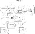
- Fig. 1 is a view illustrating an entire configuration in the first embodiment of the present invention. Meanwhile, a part related to a control unit is omitted in Fig. 1 .
- Fig. 2 is a view illustrating a specific configuration of a heating device in Fig. 1 .
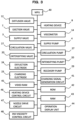
- Fig. 3 is a block diagram describing the control unit of an inkjet recording device in the first embodiment.
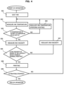
- Fig. 4 is a flowchart illustrating control according to the first embodiment of the present invention.
- a main ink container 1 is filled with an ink 2a, and the main ink container 1 is connected to a nozzle 9 via an ink supply path to supply the ink 2a to the nozzle 9.
- the main ink container 1, a supply valve 3, a supply pump 4, a main filter 5, a pressure regulating valve 6, an ejection valve 7, a heating device 8, and the nozzle 9 are connected to each other by an ink supply pipe 30 to communicate with each other.
- the ink 2a can be supplied to the nozzle 9.
- the ink 2a is changed into ink particles by the nozzle 9, and the ink particles flow to a printing object 26 via a charging electrode 23 and a deflection electrode 24, and printing is performed.
- the charging electrode 23 the amount of electric charge corresponding to printing characters is applied to the ink particles.
- the ink particles are deflected according to the amount of electric charge by the deflection electrode 24 to fly and land on the printing object 26.
- non-charged ink particles (ink particles to which electric charge is not applied by the charging electrode 23) which are not used for printing travel straight and are captured by a gutter 11.
- the ink captured by the gutter 11 is recovered to the main ink container 1 via an ink recovery path to be reused.
- the gutter 11, a recovery pump 29, and the main ink container 1 are connected to each other by an ink recovery pipe 13. Accordingly, the ink captured by the gutter 11 can be recovered to the main ink container 1.
- the viscosity of the ink 2a (ink viscosity) in the main ink container 1 is measured (detected) by a viscometer 14 that measures (detects) the viscosity of the ink.
- the viscometer 14 in this embodiment is provided in the middle of an ink path that starts from the main ink container 1 to return to the main ink container 1 via a diffusion valve 12 and a circulation pump 28.
- the viscometer 14 may be provided in the middle of the ink supply path that supplies the ink to the nozzle.
- a sub-ink container 25 is filled with a replenishment ink 2b, and the replenishment ink 2b is connected to a replenishment valve 15, the supply valve 3, and the supply pump 4 by an ink replenishment pipe 16.
- the auxiliary ink supply unit is not limited to the configuration described in this embodiment, and may have any configuration as long as the configuration enables the supply of an auxiliary ink to the main ink container 1.
- an ink cartridge may be provided in an upper portion of the main ink container, and the auxiliary ink may be supplied from the ink cartridge.
- the replenishment ink 2b is supplied to the main ink container 1.
- the ink viscosity detection value of the viscometer 14
- the replenishment ink 2b is supplied to the main ink container 1. This control will be described later.
- An intensifying liquid container 17 is filled with an intensifying liquid 18.
- a solvent is used as the intensifying liquid.
- the intensifying liquid container 17, an intensifying liquid pump 19, an intensifying valve 20, and the main ink container 1 are connected to each by an intensifying liquid replenishment pipe 21 to communicate with each other. Accordingly, a solvent replenishment unit is formed to be able to supply the intensifying liquid (solvent) 18 to the main ink container 1.
- the solvent replenishment unit is not limited to the configuration described in this embodiment, and may have any configuration as long as the configuration enables the supply of the solvent to the main ink container.
- the main ink container 1 is connected to a discharge pipe 22.
- the intensifying liquid 18 is supplied to the main ink container 1 to regulate (control) the viscosity.
- this control is executed by the control unit to be described later.
- the supply of the intensifying liquid is performed by a path in which the intensifying liquid container 17, the intensifying liquid pump 19, the intensifying valve 20, and the main ink container 1 are connected to each other by the intensifying liquid replenishment pipe 21.
- the heating device 8 includes a heating block 31, a block lid 32, a PTC heater 33, a thermistor 34, an ink chamber 35, a heater plate 36, and an elastic member 37.
- the thermistor 34 detects ink temperature inside the heating device. In a control operation of the embodiment to be described later, the ink temperature is detected by the thermistor 34, and ink temperature inside the nozzle is estimated based on the detection value.
- the detected temperature may be used.
- the ink temperature may be detected by thermometers other than the thermistor.
- a thermometer which directly detects ink temperature inside the nozzle may be installed.
- the heating device 8 is not limited to the type illustrated in Fig. 2 , and any heating device may be used as long as the heating device has a function of raising the ink temperature and can be attached to the device.
- the control unit includes a microprocessing unit (MPU) 40 that controls the entirety of the inkjet recording device, a random access memory (RAM) 43 that temporarily stores data in the inkjet recording device, a read only member (ROM) 42 that stores a program or the like in advance, and an operation display unit 44 on which an instruction for an operation is performed or which displays an operation state or the like.
- MPU microprocessing unit
- RAM random access memory
- ROM read only member
- control unit includes a video RAM 45 that stores video data for charging ink particles 10, a charging signal generation circuit 41 that converts the video data into a charging signal, a nozzle drive circuit 47 that drives the nozzle 9, a heating device control circuit 46 that controls the heating device 8, and an ink viscosity control circuit 48 that controls ink viscosity.
- the heating device control circuit 46 controls the ink temperature of the ink, which flows into the heating device 8, based on an instruction (command) of the MPU 40.
- the ink viscosity control circuit 48 performs control such that the solvent (intensifying liquid) and the replenishment ink are supplied to the main ink container 1 based on the detection value of the viscometer 14 to adjust the ink viscosity at a predetermined value or in a predetermined range.
- Each of the components is connected to the MPU 40 by a bus, and is controlled according to an instruction of the MPU 31. Incidentally, since the other components in Fig. 3 have already been described, the descriptions will be omitted here.
- Fig. 4 is an operation flowchart of one embodiment of the present invention.
- Fig. 5 is a graph showing a relationship between ambient temperature and ink temperature inside the nozzle when the set value of temperature control is set low to execute ink heating control.
- Fig. 6 is a graph showing a relationship between ambient temperature and ink viscosity when the control of Fig. 5 is executed.
- Fig. 7 is a graph showing a relationship between ambient temperature and printing character size when the control of Fig. 5 is executed.
- Fig. 8 is a graph showing a case where the set value of temperature control is set high to raise ink temperature.
- Fig. 5 is a graph showing a relationship between ambient temperature and ink temperature inside the nozzle when the set value of temperature control is set low to execute ink heating control.
- Fig. 6 is a graph showing a relationship between ambient temperature and ink viscosity when the control of Fig. 5 is executed.
- Fig. 7 is a graph showing a relationship between ambient temperature and printing character
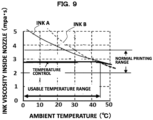
- Fig. 9 is a graph showing a relationship between ambient temperature and ink viscosity when the control of Fig. 8 is executed.
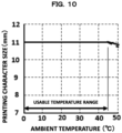
- Fig. 10 is a graph showing a relationship between ambient temperature and printing character size when the control of Fig. 8 is executed.
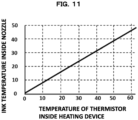
- Fig. 11 is a graph showing a relationship between temperature inside the heating device and ink temperature inside the nozzle.
- Fig. 12 is a graph showing a relationship between ink particle speed and printing character size.
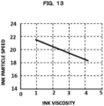
- Fig. 13 is a graph showing a relationship between ink viscosity and ink particle speed.
- each of the supply pump 4, the recovery pump 29, and the intensifying liquid pump 19 illustrated in Fig. 1 operates, the supply valve 3 and the ejection valve 7 open, and the ink of which the pressure is regulated at an arbitrary pressure by the pressure regulating valve 6 is supplied to the nozzle 9 via the heating device 8. Then, ink particles are ejected from the nozzle 9.
- This process (operation) is step S01 of Fig. 4 .
- a nozzle drive voltage excitation voltage
- the ejected ink is atomized by the surface tension of the ink.
- the state of the ink particles is greatly affected by the ink viscosity in addition to the drive voltage and the surface tension of the ink, and affects printing characters.
- Fig. 13 shows a relationship between ink viscosity and ink particle speed
- Fig. 12 shows a relationship between ink particle speed and the printing character size.
- the ink viscosity is affected by the ink temperature. Namely, it can be seen that the ink viscosity decreases as the ink temperature increases, and the ink viscosity increases as the ink temperature decreases.
- step S02 the ink temperature is detected.
- the measurement of temperature is performed by the thermistor 34 assembled in the heating device 8 illustrated in Fig. 2 .
- the ink temperature detected by the thermistor is different from the temperature of the ink (ink particles) ejected from the nozzle 9; however, since the distance between the heating device 8 and the nozzle 9 is short, both the temperatures can be considered to be substantially the same temperature.
- the relationship between the detected temperature of the thermistor and ink temperature inside the nozzle is obtained in advance as shown in Fig. 11 , and the ink temperature inside the nozzle is estimated from the temperature of the thermistor to accurately obtain the ink temperature of the ink particles ejected from the nozzle 9.
- step S03 it is determined whether or not the ink temperature inside the nozzle 9 is a temperature close to the maximum value of a temperature range corresponding to the range of ink viscosity in which normal printing can be executed.
- a value slightly smaller than the maximum value of the amount of use of the ink (hereinafter, referred to as a maximum proximity value) is selected as a set value.
- the temperature set value will be described as 45°C.
- temperature control can be performed as long as a set temperature when the heating device 8 performs heating is in the temperature range (in a usable temperature range) corresponding to the ink viscosity at which normal printing can be executed.
- the range of temperature control becomes narrow, which is not preferable.
- the range in which temperature control is executed can be expanded, and the amount of use of the solvent can be reduced, which is preferable.
- the process proceeds to step S04.
- the ink temperature has already reached 45°C which is the set value, the process proceeds to step S05. Namely, the PTC heater 33 of the heating device 8 is heated by the heating device control circuit 46 to reach 45°C.
- step S04 heating control is executed such that the ink temperature reaches the set temperature.
- the heating device control circuit 46 performs control to heat the PTC heater 33 of the heating device 8 such that the temperature of the ink ejected from the nozzle 9 reaches 45°C. Specifically, control is performed as shown in Fig. 9 . Since the ink viscosity is lowered by this heating control, even when the amount of use of the solvent is reduced, the ink viscosity can be controlled to be constant, and the amount of use of the solvent can be reduced.
- the heating device 8 has a quick effect in that the heating device 8 instantly raises the ink temperature, so that the ink temperature is quickly controlled, and the regulation of the ink viscosity of the ink to be supplied to the nozzle 9 is performed.
- step S05 the ink viscosity is detected by the viscometer 14. As a result of the detection, when the ink viscosity is determined to be a viscosity out of the range in which normal printing is performed, the process proceeds to step S07.
- step S07 control is performed such that the intensifying liquid (solvent) in the intensifying liquid container 17 or the replenishment ink in the sub-ink container 25 is supplied to the main ink container 1 to adjust the ink viscosity at the predetermined value or in the predetermined range (range of ink viscosity in which normal printing can be executed).
- the ink viscosity is higher than the predetermined value or a normal range, basically, the solvent is supplied.
- control is performed to supply the replenishment ink to adjust the ink viscosity of the ink 2a in the main ink container 1.
- This control can be performed without problem as long as the ink viscosity is in the range of ink viscosity in which normal printing can be executed, but in this embodiment, the control is performed until the ink viscosity reaches the median value of the range.
- the ink 2b in the sub-ink container 25 is replenished to the main ink container 1 via the replenishment valve 15, the supply pump 4, the pressure regulating valve 6, the heating device 8, the nozzle 9, the gutter 11, and the recovery pump 29.
- the detection value is higher than the viscosity value which is the median value of the normal printing range of the relationship between ambient temperature and ink viscosity shown in Fig.
- the intensifying liquid 18 in the intensifying liquid container 17 is replenished to the main ink container 1 via the intensifying liquid pump 19 and the intensifying valve 20.
- This control is performed by the ink viscosity control circuit 48 (refer to Fig. 3 ), and the ink viscosity is controlled to reach the viscosity value which is the median value of the normal printing range.
- Printing is performed with the ink controlled at the ink temperature inside the nozzle 9 which is controlled at 45°C in the vicinity of the maximum value of the usable temperature range, and at the ink viscosity in the vicinity of the median value of the normal printing range, so that characters can be stably printed.
- characters can be printed in a constant size without being affected by ambient temperature.
- step S08 characters are printed after such a process is performed. Namely, printing is performed in such a manner that the ink of which the ink viscosity is regulated is supplied to the nozzle 9, and the ink particles charged by the charging electrode 23 are deflected by the deflection electrode 24 to land on a printing object. In addition, non-charged ink particles among the ejected ink particles travel straight and are captured by the gutter 11 to return to the main ink container 1 via the recovery pump 29.
- This control is executed by the control unit illustrated in Fig. 3 .
- step S09 it is determined whether or not the scheduled printing is completed and stopped. If the scheduled printing work is not completed (when printing is desired to be continued), the process proceeds to step S02. When the scheduled printing work is completed, the operation is stopped.
- Figs. 5 to 7 show a case where the set value of temperature control is set to a low value and ink temperature control is executed by the heating device when ambient temperature is a relatively low temperature.
- the set value for example, 15°C
- heating is performed such that the ink temperature is 15°C.
- the set value for example, 15°C
- the temperature cannot be controlled.
- the ink temperature depends on ambient temperature, the ink temperature cannot be controlled by the heating device.
- the ink viscosity is lower than the normal printing region and thus leading to a high possibility of printing failure.
- the character size increases depending on temperature (size of the ink particles forming characters increase), which is a problem.
- the reason the character size differs depending on temperature is that as shown in Figs. 6 , 12 , and 13 , there is a relationship that the ink viscosity changes depending on the ink temperature, the ink particle speed changes depending on the ink viscosity, and the printing character size changes depending on the ink particle speed.
- the set temperature is set to a high set value so as to be in a range from the median value to the median value of a usage temperature range (in the above-described embodiment, 45°C is selected as the set value as shown in Fig. 8 ), as shown in Fig. 9 , the range of temperature control is expanded, and even when ambient temperature greatly varies, the ink viscosity can be maintained in the normal range by heating control by the heating device 8. As a result, as shown in Fig. 10 , the printing character size can be made constant. Therefore, the higher the temperature set value for temperature control is, the more optimally control can be performed.
- the ink viscosity control circuit 48 (refer to Fig. 3 ) causes the solvent or the replenishment ink to be supplied to the main ink container 1 to control the ink viscosity of the ink 2a.
- the amount of use of the solvent can be reduced and normal printing can be performed. Namely, since ink viscosity control by temperature control is performed, the dependence of the ink viscosity control on the solvent can be reduced, and the ink temperature can be instantly raised to regulate the ink viscosity to an optimum level.
- a second embodiment of the present invention will be described.
- the state of ink particles (particle size or speed of ink particles) ejected at the nozzle 9 is regulated to coincide with an ideal state, which is assumed in advance, by the control of the heating device 9.
- the entire configuration of an inkjet recording device in the second embodiment is the configuration of Fig. 1 which is the same as in the first embodiment. Since the configuration of Fig. 1 has already been described, duplicated descriptions will be omitted.
- Fig. 14 is a flowchart illustrating control of the inkjet recording device in the second embodiment of the present invention.
- Fig. 15 is a view illustrating a configuration of the nozzle 9 of the inkjet recording device.
- the nozzle 9 includes a piezoelectric element 50, a nozzle body 51, an orifice plate 52, and an ink flow path 53.
- the nozzle drive circuit 47 applies an excitation voltage to the piezoelectric element, and the piezoelectric element 50 is excited by the excitation voltage (nozzle drive voltage) to cause pressure pulsation in an ink flowing in the ink flow path 53.
- the control unit controls the nozzle drive circuit 47 to regulate the excitation voltage and thus controls the state of the ink particles to be optimized.
- the excitation voltage is set to a constant voltage determined by the type of an ink to be used, and the ink temperature is regulated by the heating device to regulate the ink viscosity during operation to an optimum level to optimize the state of the ink particles.
- Fig. 14 when operation is started, first, the type of an ink to be used (ink in the main ink container 1) is input.
- the input of the type of the ink may be an input from the operation display unit 44 of the control unit illustrated in Fig. 3 by an operator, or may be performed in such a manner that information regarding the type of the ink displayed on a label or the like of an ink bottle is automatically read out on a device side.
- This operation is step S10. After step S10, the process proceeds to step S01.
- step S01 the ink is supplied to the nozzle 9, and ink particles are ejected from the nozzle.
- the operation of step S01 is the same operations as step S01 of Fig. 4 which has already been described. After the operation of step S01, the process proceeds to step S11.
- step S11 it is determined whether or not the ink has a high viscosity specification, based on a determination criterion determined in advance as to whether or not the ink viscosity is a high viscosity.
- a determination criterion a reference viscosity is determined which is a determination criterion, and when the viscosity is the reference viscosity or higher, the viscosity is determined to be a high viscosity.
- the process proceeds to step S12.
- step S13 the reason for distinguishing between a high viscosity ink and a non-high viscosity ink is that in the case of a high-viscosity ink, in order to reduce the use of the solvent as much as possible, the control of setting temperature in the vicinity of the maximum usage temperature of the ink is performed. In the case of a relatively low viscosity, in order to relax the limitation, the excitation curve of the ink is used which is obtained in advance and represents a relationship between temperature and excitation voltage.
- step S12 the excitation voltage is set such that an excitation voltage at temperature in the vicinity of the maximum usage temperature of the ink (45°C) is applied to the nozzle.
- the excitation voltage at which the ink particles are in an appropriate state in the vicinity of the maximum value (45°C in this example) of the usage temperature of the ink having a high viscosity specification is set to be supplied to the piezoelectric element 50 of the nozzle 9.
- step S13 the excitation curve (relationship between temperature and excitation voltage) of the ink used which is obtained in advance is selected, and the process proceeds to step S14.
- step S14 the ink temperature inside the heating device is measured.
- step S15 the measured ink temperature is used to set the excitation voltage such that an excitation voltage corresponding to the measured temperature of the ink used is applied to the nozzle. Namely, the excitation voltage at which the ink particles of the ink used are in an appropriate state is set to be supplied to the piezoelectric element 50 of the nozzle 9.
- step S16 the excitation curve (relationship between temperature and excitation voltage) of the ink used which is obtained in advance is selected, and the process proceeds to step S14.
- step S14 the ink temperature inside the heating device is measured.
- step S15 the measured ink temperature is used to set the excitation voltage such that an excitation voltage corresponding to the measured temperature of the ink used is applied to the nozzle. Namely, the excitation voltage at which the ink particles of the
- step S02 the ink temperature is measured, and in step S03, it is determined whether or not the temperature is the set temperature (45°C in this embodiment) set in the vicinity of the maximum temperature of the ink.
- the process proceeds to step S04, and the heating device 8 is controlled to regulate the ink temperature (perform heating) to the set temperature.
- step S05 the process proceeds to step S05.
- step S05 the ink viscosity is measured by the viscometer 14, and in step S06, it is determined whether or not the ink viscosity is in the range of viscosity which enables printing.
- the process proceeds to step S07, and the control of regulating the ink viscosity is executed.
- the process proceeds to step S08, and printing is executed. Then, when predetermined printing work is completed (case of YES in step S09), the operation of the device ends.
- step S16 similar to step S05, the ink viscosity is measured.
- step S17 similar to step S06, it is determined whether or not the ink is in the viscosity range which enables printing, and when the ink viscosity is not in the range which enables printing (case of NO), the process proceeds to step S18, and the control of regulating the ink viscosity is executed.
- step S17 When the ink viscosity is in the range which enables printing in step S17 (case of YES), the process proceeds to step S19, and printing is executed. Then, when predetermined printing work is completed (case of YES in step S20), the operation of the device ends.
- ink heating control can be performed by the heating device to control the state of the ink particles at the nozzle to an optimum state for printing. Accordingly, even when the excitation voltage is not regulated, ink particles with which optimum printing can be performed can be ejected from the nozzle 9.
Landscapes
- Engineering & Computer Science (AREA)
- Quality & Reliability (AREA)
- Ink Jet (AREA)
- Particle Formation And Scattering Control In Inkjet Printers (AREA)
Claims (12)
- Dispositif d'enregistrement à jet d'encre comprenant :une buse (9) qui atomise une encre pour éjecter des particules d'encre ;une électrode de charge (23) qui charge les particules d'encre, qui ont été éjectées de la buse (9), pour correspondre à un caractère d'impression ;une électrode de déviation (24) qui dévie les particules d'encre chargées qui sont passées à travers l'électrode de charge (23) ;une gouttière (11) qui capture une encre non chargée ;un chemin d'alimentation en encre (30) qui alimente l'encre dans un récipient d'encre principal (1) du dispositif d'enregistrement à jet d'encre à la buse (9) ;un chemin de récupération d'encre (13) qui récupère l'encre non chargée, qui a été capturée par la gouttière (11), vers le récipient d'encre principal (1) ;une unité de réapprovisionnement en solvant (25) qui alimente un solvant au récipient d'encre principal (1) ; etle dispositif d'enregistrement à jet d'encre comprend en outre une unité de commande (40) qui est configurée pour commander une totalité du dispositif,dans lequel un dispositif de chauffage (8) qui est installé entre le chemin d'alimentation en encre et la buse (9) pour chauffer l'encre,un thermomètre (34) qui détecte une température d'encre de l'encre chauffée par le dispositif de chauffage (8), etun viscosimètre (14) qui détecte une viscosité de l'encre dans le récipient d'encre principal (1) sont prévus, etl'unité de commande est configurée pour commander le dispositif de chauffage (8) sur la base de la température détectée par le thermomètre de sorte que la température atteigne une température de consigne réglée dans une plage d'une viscosité d'encre qui permet l'impression, et commande une quantité d'alimentation en solvant sur la base d'une valeur de détection du viscosimètre pour réguler la viscosité de l'encre dans le récipient d'encre principal (1) à une viscosité d'encre prédéterminée.
- Dispositif d'enregistrement à jet d'encre selon la revendication 1,
dans lequel la température de consigne est dans une plage d'une valeur médiane à une valeur maximale d'une plage de température d'utilisation correspondant à la plage de la viscosité d'encre qui permet l'impression. - Dispositif d'enregistrement à jet d'encre selon la revendication 1,
dans lequel l'unité de commande est configurée pour commander l'unité de réapprovisionnement en solvant pour alimenter le solvant au récipient d'encre principal (1) de sorte que la viscosité atteigne une valeur médiane de la plage de la viscosité d'encre qui permet l'impression. - Dispositif d'enregistrement à jet d'encre selon la revendication 1,dans lequel une unité d'alimentation en encre auxiliaire est prévue qui alimente une encre auxiliaire au récipient d'encre principal, etle solvant ou l'encre auxiliaire est alimenté au récipient d'encre principal (1) pour réguler la viscosité à la viscosité d'encre prédéterminée.
- Dispositif d'enregistrement à jet d'encre selon la revendication 1,
dans lequel l'unité de commande est configurée pour appliquer une tension d'excitation, qui correspond à l'encre à utiliser, à la buse (9), régler la température de consigne à une température à laquelle un état des particules d'encre est approprié à la tension d'excitation, et commander le dispositif de chauffage (8). - Dispositif d'enregistrement à jet d'encre selon la revendication 1,
dans lequel l'unité de commande est configurée pour déterminer si l'encre à utiliser a ou non une spécification de viscosité élevée, sur la base d'un critère de détermination déterminé à l'avance quant à savoir si la viscosité est élevée ou non, appliquer une tension d'excitation, qui correspond à une température d'utilisation maximale de l'encre, à la buse (9) lorsque la viscosité est déterminée comme étant élevée, et appliquer la tension d'excitation, qui correspond à la température d'encre, à la buse (9) lorsque la viscosité est déterminée comme n'étant pas élevée. - Procédé de commande d'un dispositif d'enregistrement à jet d'encre incluant une buse (9) qui atomise une encre pour éjecter des particules d'encre, une électrode de charge (23) qui charge les particules d'encre, qui ont été éjectées de la buse (9), pour correspondre à un caractère d'impression, une électrode de déviation (24) qui dévie les particules d'encre chargées qui sont passées à travers l'électrode de charge (23), une gouttière (11) qui capture une encre non chargée, un chemin d'alimentation en encre (30) qui alimente l'encre dans un récipient d'encre principal (1) du dispositif d'enregistrement à jet d'encre à la buse, un chemin de récupération d'encre (13) qui récupère l'encre non chargée, qui a été capturée par la gouttière (11), vers le récipient d'encre principal (1), et une unité de réapprovisionnement en solvant (25) qui alimente un solvant au récipient d'encre principal (1),
dans lequel le dispositif d'enregistrement à jet d'encre comprend un dispositif de chauffage (8) qui est installé entre le chemin d'alimentation en encre et la buse (9) pour chauffer l'encre, un thermomètre (34) qui détecte une température de l'encre chauffée par le dispositif de chauffage (8), et un viscosimètre qui détecte une viscosité de l'encre dans le récipient d'encre principal (1) sont prévus, le procédé comprenant :
la commande du dispositif de chauffage (8) sur la base d'une température de consigne réglée dans une plage d'une viscosité d'encre qui permet une impression normale et de la température de l'encre détectée par le thermomètre, et la réalisation d'une commande de sorte que le solvant ou l'encre de réapprovisionnement est alimenté au récipient d'encre principal (1) sur la base d'une valeur de détection du viscosimètre pour amener la viscosité à être dans la plage qui permet l'impression. - Procédé de commande d'un dispositif d'enregistrement à jet d'encre selon la revendication 7,
dans lequel la température de consigne est dans une plage d'une valeur médiane à une valeur maximale d'une plage de température d'utilisation correspondant à la plage de la viscosité d'encre qui permet une impression normale. - Procédé de commande d'un dispositif d'enregistrement à jet d'encre selon la revendication 7,
dans lequel une commande est réalisée pour alimenter le solvant au récipient d'encre principal (1) de sorte que la viscosité atteigne une valeur médiane de la plage qui permet une impression normale. - Procédé de commande d'un dispositif d'enregistrement à jet d'encre selon la revendication 7,
dans lequel le solvant ou une encre auxiliaire provenant d'une unité d'alimentation en encre auxiliaire est alimenté au récipient d'encre principal (1) pour réguler la viscosité à une viscosité d'encre prédéterminée. - Procédé de commande d'un dispositif d'enregistrement à jet d'encre selon la revendication 7,
dans lequel une tension d'excitation correspondant à l'encre à utiliser est appliquée à la buse (9), la température de consigne est réglée à une température à laquelle un état des particules d'encre est approprié à la tension d'excitation, et le dispositif de chauffage (8) est commandé. - Procédé de commande d'un dispositif d'enregistrement à jet d'encre selon la revendication 7,
dans lequel il est déterminé si l'encre à utiliser a ou non une spécification de viscosité élevée, sur la base d'un critère de détermination déterminé à l'avance quant à savoir si la viscosité est élevée ou non, une tension d'excitation correspondant à une température d'utilisation maximale de l'encre est appliquée à la buse (9) lorsque la viscosité est déterminée comme étant élevée, et la tension d'excitation correspondant à la température de l'encre est appliquée à la buse (9) lorsque la viscosité est déterminée comme n'étant pas élevée.
Applications Claiming Priority (2)
| Application Number | Priority Date | Filing Date | Title |
|---|---|---|---|
| JP2019012986 | 2019-01-29 | ||
| PCT/JP2020/003046 WO2020158759A1 (fr) | 2019-01-29 | 2020-01-28 | Dispositif d'enregistrement à jet d'encre et procédé de commande de dispositif d'enregistrement à jet d'encre |
Publications (3)
| Publication Number | Publication Date |
|---|---|
| EP3919281A1 EP3919281A1 (fr) | 2021-12-08 |
| EP3919281A4 EP3919281A4 (fr) | 2022-10-26 |
| EP3919281B1 true EP3919281B1 (fr) | 2024-12-11 |
Family
ID=71841859
Family Applications (1)
| Application Number | Title | Priority Date | Filing Date |
|---|---|---|---|
| EP20748716.6A Active EP3919281B1 (fr) | 2019-01-29 | 2020-01-28 | Dispositif d'enregistrement à jet d'encre et procédé de commande de dispositif d'enregistrement à jet d'encre |
Country Status (5)
| Country | Link |
|---|---|
| US (1) | US11541654B2 (fr) |
| EP (1) | EP3919281B1 (fr) |
| JP (1) | JP7223780B2 (fr) |
| CN (1) | CN113365843B (fr) |
| WO (1) | WO2020158759A1 (fr) |
Families Citing this family (7)
| Publication number | Priority date | Publication date | Assignee | Title |
|---|---|---|---|---|
| JP7567280B2 (ja) * | 2020-08-21 | 2024-10-16 | ブラザー工業株式会社 | 液体吐出装置、その制御方法及びプログラム |
| JP7548019B2 (ja) * | 2021-01-04 | 2024-09-10 | セイコーエプソン株式会社 | 液体噴射装置 |
| JP7602442B2 (ja) * | 2021-08-10 | 2024-12-18 | 株式会社日立産機システム | インクジェット記録装置、及びインクジェット記録方法 |
| US20250332827A1 (en) * | 2022-04-27 | 2025-10-30 | Hitachi Industrial Equipment Systems Co., Ltd. | Inkjet Marking Apparatus and Inkjet Marking System |
| JPWO2024161491A1 (fr) * | 2023-01-31 | 2024-08-08 | ||
| KR102663457B1 (ko) * | 2023-08-01 | 2024-05-03 | 송복면 | 무한 잉크공급 장치를 구비한 프린터 |
| GB202319193D0 (en) * | 2023-12-14 | 2024-01-31 | Videojet Technologies Inc | Printer |
Family Cites Families (11)
| Publication number | Priority date | Publication date | Assignee | Title |
|---|---|---|---|---|
| JPS5816851A (ja) | 1981-07-24 | 1983-01-31 | Konishiroku Photo Ind Co Ltd | インクジエツトプリンタ |
| US4860027A (en) | 1988-03-18 | 1989-08-22 | A. B. Dick Company | Ink drop control system with temperature compensation |
| JP2002059563A (ja) | 2000-08-21 | 2002-02-26 | Kishu Giken Kogyo Kk | インクジェットプリンタ |
| JP4247704B2 (ja) | 2001-09-11 | 2009-04-02 | セイコーエプソン株式会社 | 液滴吐出装置とその液体充填方法、およびデバイス製造装置とデバイス製造方法 |
| JP2004066499A (ja) | 2002-08-02 | 2004-03-04 | Hitachi Home & Life Solutions Inc | インクジェット記録装置 |
| JP2008137198A (ja) | 2006-11-30 | 2008-06-19 | Kishu Giken Kogyo Kk | インクジェットプリンタ |
| JP2009179023A (ja) | 2008-02-01 | 2009-08-13 | Hitachi Industrial Equipment Systems Co Ltd | インクジェット記録装置 |
| EP2465681B1 (fr) * | 2009-08-11 | 2014-11-05 | Hitachi Industrial Equipment Systems Co., Ltd. | Dispositif d'enregistrement à jet d'encre et tête d'impression |
| JP5956279B2 (ja) | 2012-08-08 | 2016-07-27 | 株式会社日立産機システム | 気液分離器、及びそれを備えたインクジェット記録装置 |
| JP6247895B2 (ja) | 2013-10-28 | 2017-12-13 | 株式会社日立産機システム | インクジェット記録装置 |
| FR3049214B1 (fr) * | 2016-03-22 | 2018-04-27 | Dover Europe Sarl | Debimetre et son utilisation dans une imprimante |
-
2020
- 2020-01-28 US US17/424,524 patent/US11541654B2/en active Active
- 2020-01-28 EP EP20748716.6A patent/EP3919281B1/fr active Active
- 2020-01-28 JP JP2020569657A patent/JP7223780B2/ja active Active
- 2020-01-28 WO PCT/JP2020/003046 patent/WO2020158759A1/fr not_active Ceased
- 2020-01-28 CN CN202080011473.5A patent/CN113365843B/zh active Active
Also Published As
| Publication number | Publication date |
|---|---|
| US20220072847A1 (en) | 2022-03-10 |
| EP3919281A1 (fr) | 2021-12-08 |
| CN113365843B (zh) | 2022-10-21 |
| WO2020158759A1 (fr) | 2020-08-06 |
| EP3919281A4 (fr) | 2022-10-26 |
| JP7223780B2 (ja) | 2023-02-16 |
| CN113365843A (zh) | 2021-09-07 |
| JPWO2020158759A1 (ja) | 2021-11-25 |
| US11541654B2 (en) | 2023-01-03 |
Similar Documents
| Publication | Publication Date | Title |
|---|---|---|
| EP3919281B1 (fr) | Dispositif d'enregistrement à jet d'encre et procédé de commande de dispositif d'enregistrement à jet d'encre | |
| EP2701916B1 (fr) | Compensation de changements de capacitance dans des éléments de tête d'impression piézoélectriques | |
| JPH05201025A (ja) | ジェット印刷用ドロップの品質制御方法及び装置 | |
| US9346262B2 (en) | Liquid ejecting apparatus and liquid ejecting method | |
| US8292392B2 (en) | System and method for modifying operation of an inkjet printer to accommodate changing environmental conditions | |
| JP2001270090A (ja) | インク噴射式印刷装置 | |
| JP2018099791A (ja) | インク供給システムおよびインクジェットプリンタ | |
| US8491075B2 (en) | Method and apparatus for controlling jetting performance in an inkjet printer | |
| US5122816A (en) | Printer means having an electrothermally operated printing head | |
| JP2013144371A (ja) | 液滴吐出装置 | |
| JP5199591B2 (ja) | インクジェットプリンタ | |
| JP2021074920A (ja) | インクジェット記録装置及びインク送液制御方法 | |
| JP2018094805A (ja) | インクジェット装置 | |
| JP2009012188A (ja) | インクジェット記録装置 | |
| JP6553958B2 (ja) | インクジェット記録装置およびそれに用いるインク温度の制御方法 | |
| JP5271014B2 (ja) | インクジェット記録装置及びインクジェット記録装置の制御方法 | |
| JP2002036595A (ja) | インクジェット記録装置 | |
| JP2015089654A (ja) | インクジェットプリンタ | |
| JP7214403B2 (ja) | 静電容量センサ、及び、印刷装置 | |
| US7802860B2 (en) | Liquid ejecting apparatus and method for determining liquid depletion to maintain a pressure differential between an ink jet head and ink cartridge | |
| WO2018030118A1 (fr) | Appareil d'enregistrement à jet d'encre et réservoir d'encre utilisé dans celui-ci | |
| EP3484711B1 (fr) | Améliorations apportées ou se rapportant à des imprimantes à jet d'encre continu | |
| JP2024063656A (ja) | 液体吐出検査装置 | |
| WO2024161491A1 (fr) | Dispositif d'impression à jet d'encre et procédé de commande de dispositif d'impression à jet d'encre | |
| US12103316B2 (en) | Image forming apparatus, lifetime determination method and non-transitory computer-readable recording medium storing lifetime determination program |
Legal Events
| Date | Code | Title | Description |
|---|---|---|---|
| STAA | Information on the status of an ep patent application or granted ep patent |
Free format text: STATUS: THE INTERNATIONAL PUBLICATION HAS BEEN MADE |
|
| PUAI | Public reference made under article 153(3) epc to a published international application that has entered the european phase |
Free format text: ORIGINAL CODE: 0009012 |
|
| STAA | Information on the status of an ep patent application or granted ep patent |
Free format text: STATUS: REQUEST FOR EXAMINATION WAS MADE |
|
| 17P | Request for examination filed |
Effective date: 20210830 |
|
| AK | Designated contracting states |
Kind code of ref document: A1 Designated state(s): AL AT BE BG CH CY CZ DE DK EE ES FI FR GB GR HR HU IE IS IT LI LT LU LV MC MK MT NL NO PL PT RO RS SE SI SK SM TR |
|
| DAV | Request for validation of the european patent (deleted) | ||
| DAX | Request for extension of the european patent (deleted) | ||
| A4 | Supplementary search report drawn up and despatched |
Effective date: 20220926 |
|
| RIC1 | Information provided on ipc code assigned before grant |
Ipc: B41J 2/18 20060101ALI20220920BHEP Ipc: B41J 2/07 20060101ALI20220920BHEP Ipc: B41J 2/03 20060101ALI20220920BHEP Ipc: B41J 2/185 20060101ALI20220920BHEP Ipc: B41J 2/175 20060101ALI20220920BHEP Ipc: B41J 2/17 20060101ALI20220920BHEP Ipc: B41J 2/02 20060101ALI20220920BHEP Ipc: B41J 2/195 20060101AFI20220920BHEP |
|
| REG | Reference to a national code |
Ref country code: DE Ref legal event code: R079 Ipc: B41J0029380000 Ref country code: DE Ref legal event code: R079 Ref document number: 602020042970 Country of ref document: DE Free format text: PREVIOUS MAIN CLASS: B41J0002195000 Ipc: B41J0029380000 |
|
| GRAP | Despatch of communication of intention to grant a patent |
Free format text: ORIGINAL CODE: EPIDOSNIGR1 |
|
| STAA | Information on the status of an ep patent application or granted ep patent |
Free format text: STATUS: GRANT OF PATENT IS INTENDED |
|
| RIC1 | Information provided on ipc code assigned before grant |
Ipc: B41J 29/38 20060101AFI20240620BHEP |
|
| INTG | Intention to grant announced |
Effective date: 20240710 |
|
| GRAS | Grant fee paid |
Free format text: ORIGINAL CODE: EPIDOSNIGR3 |
|
| GRAA | (expected) grant |
Free format text: ORIGINAL CODE: 0009210 |
|
| STAA | Information on the status of an ep patent application or granted ep patent |
Free format text: STATUS: THE PATENT HAS BEEN GRANTED |
|
| AK | Designated contracting states |
Kind code of ref document: B1 Designated state(s): AL AT BE BG CH CY CZ DE DK EE ES FI FR GB GR HR HU IE IS IT LI LT LU LV MC MK MT NL NO PL PT RO RS SE SI SK SM TR |
|
| REG | Reference to a national code |
Ref country code: GB Ref legal event code: FG4D |
|
| REG | Reference to a national code |
Ref country code: CH Ref legal event code: EP |
|
| REG | Reference to a national code |
Ref country code: DE Ref legal event code: R096 Ref document number: 602020042970 Country of ref document: DE |
|
| REG | Reference to a national code |
Ref country code: IE Ref legal event code: FG4D |
|
| REG | Reference to a national code |
Ref country code: LT Ref legal event code: MG9D |
|
| PG25 | Lapsed in a contracting state [announced via postgrant information from national office to epo] |
Ref country code: HR Free format text: LAPSE BECAUSE OF FAILURE TO SUBMIT A TRANSLATION OF THE DESCRIPTION OR TO PAY THE FEE WITHIN THE PRESCRIBED TIME-LIMIT Effective date: 20241211 |
|
| PG25 | Lapsed in a contracting state [announced via postgrant information from national office to epo] |
Ref country code: FI Free format text: LAPSE BECAUSE OF FAILURE TO SUBMIT A TRANSLATION OF THE DESCRIPTION OR TO PAY THE FEE WITHIN THE PRESCRIBED TIME-LIMIT Effective date: 20241211 |
|
| PG25 | Lapsed in a contracting state [announced via postgrant information from national office to epo] |
Ref country code: BG Free format text: LAPSE BECAUSE OF FAILURE TO SUBMIT A TRANSLATION OF THE DESCRIPTION OR TO PAY THE FEE WITHIN THE PRESCRIBED TIME-LIMIT Effective date: 20241211 |
|
| REG | Reference to a national code |
Ref country code: NL Ref legal event code: MP Effective date: 20241211 |
|
| PG25 | Lapsed in a contracting state [announced via postgrant information from national office to epo] |
Ref country code: ES Free format text: LAPSE BECAUSE OF FAILURE TO SUBMIT A TRANSLATION OF THE DESCRIPTION OR TO PAY THE FEE WITHIN THE PRESCRIBED TIME-LIMIT Effective date: 20241211 |
|
| PG25 | Lapsed in a contracting state [announced via postgrant information from national office to epo] |
Ref country code: NO Free format text: LAPSE BECAUSE OF FAILURE TO SUBMIT A TRANSLATION OF THE DESCRIPTION OR TO PAY THE FEE WITHIN THE PRESCRIBED TIME-LIMIT Effective date: 20250311 |
|
| PG25 | Lapsed in a contracting state [announced via postgrant information from national office to epo] |
Ref country code: GR Free format text: LAPSE BECAUSE OF FAILURE TO SUBMIT A TRANSLATION OF THE DESCRIPTION OR TO PAY THE FEE WITHIN THE PRESCRIBED TIME-LIMIT Effective date: 20250312 Ref country code: LV Free format text: LAPSE BECAUSE OF FAILURE TO SUBMIT A TRANSLATION OF THE DESCRIPTION OR TO PAY THE FEE WITHIN THE PRESCRIBED TIME-LIMIT Effective date: 20241211 |
|
| PG25 | Lapsed in a contracting state [announced via postgrant information from national office to epo] |
Ref country code: RS Free format text: LAPSE BECAUSE OF FAILURE TO SUBMIT A TRANSLATION OF THE DESCRIPTION OR TO PAY THE FEE WITHIN THE PRESCRIBED TIME-LIMIT Effective date: 20250311 |
|
| PG25 | Lapsed in a contracting state [announced via postgrant information from national office to epo] |
Ref country code: NL Free format text: LAPSE BECAUSE OF FAILURE TO SUBMIT A TRANSLATION OF THE DESCRIPTION OR TO PAY THE FEE WITHIN THE PRESCRIBED TIME-LIMIT Effective date: 20241211 |
|
| REG | Reference to a national code |
Ref country code: AT Ref legal event code: MK05 Ref document number: 1750115 Country of ref document: AT Kind code of ref document: T Effective date: 20241211 |
|
| PG25 | Lapsed in a contracting state [announced via postgrant information from national office to epo] |
Ref country code: SM Free format text: LAPSE BECAUSE OF FAILURE TO SUBMIT A TRANSLATION OF THE DESCRIPTION OR TO PAY THE FEE WITHIN THE PRESCRIBED TIME-LIMIT Effective date: 20241211 |
|
| PG25 | Lapsed in a contracting state [announced via postgrant information from national office to epo] |
Ref country code: PL Free format text: LAPSE BECAUSE OF FAILURE TO SUBMIT A TRANSLATION OF THE DESCRIPTION OR TO PAY THE FEE WITHIN THE PRESCRIBED TIME-LIMIT Effective date: 20241211 |
|
| PG25 | Lapsed in a contracting state [announced via postgrant information from national office to epo] |
Ref country code: IS Free format text: LAPSE BECAUSE OF FAILURE TO SUBMIT A TRANSLATION OF THE DESCRIPTION OR TO PAY THE FEE WITHIN THE PRESCRIBED TIME-LIMIT Effective date: 20250411 |
|
| PG25 | Lapsed in a contracting state [announced via postgrant information from national office to epo] |
Ref country code: PT Free format text: LAPSE BECAUSE OF FAILURE TO SUBMIT A TRANSLATION OF THE DESCRIPTION OR TO PAY THE FEE WITHIN THE PRESCRIBED TIME-LIMIT Effective date: 20250411 |
|
| PG25 | Lapsed in a contracting state [announced via postgrant information from national office to epo] |
Ref country code: EE Free format text: LAPSE BECAUSE OF FAILURE TO SUBMIT A TRANSLATION OF THE DESCRIPTION OR TO PAY THE FEE WITHIN THE PRESCRIBED TIME-LIMIT Effective date: 20241211 |
|
| PG25 | Lapsed in a contracting state [announced via postgrant information from national office to epo] |
Ref country code: AT Free format text: LAPSE BECAUSE OF FAILURE TO SUBMIT A TRANSLATION OF THE DESCRIPTION OR TO PAY THE FEE WITHIN THE PRESCRIBED TIME-LIMIT Effective date: 20241211 Ref country code: RO Free format text: LAPSE BECAUSE OF FAILURE TO SUBMIT A TRANSLATION OF THE DESCRIPTION OR TO PAY THE FEE WITHIN THE PRESCRIBED TIME-LIMIT Effective date: 20241211 |
|
| PG25 | Lapsed in a contracting state [announced via postgrant information from national office to epo] |
Ref country code: SK Free format text: LAPSE BECAUSE OF FAILURE TO SUBMIT A TRANSLATION OF THE DESCRIPTION OR TO PAY THE FEE WITHIN THE PRESCRIBED TIME-LIMIT Effective date: 20241211 |
|
| PG25 | Lapsed in a contracting state [announced via postgrant information from national office to epo] |
Ref country code: CZ Free format text: LAPSE BECAUSE OF FAILURE TO SUBMIT A TRANSLATION OF THE DESCRIPTION OR TO PAY THE FEE WITHIN THE PRESCRIBED TIME-LIMIT Effective date: 20241211 |
|
| PG25 | Lapsed in a contracting state [announced via postgrant information from national office to epo] |
Ref country code: IT Free format text: LAPSE BECAUSE OF FAILURE TO SUBMIT A TRANSLATION OF THE DESCRIPTION OR TO PAY THE FEE WITHIN THE PRESCRIBED TIME-LIMIT Effective date: 20241211 |
|
| REG | Reference to a national code |
Ref country code: CH Ref legal event code: PL |
|
| PG25 | Lapsed in a contracting state [announced via postgrant information from national office to epo] |
Ref country code: SE Free format text: LAPSE BECAUSE OF FAILURE TO SUBMIT A TRANSLATION OF THE DESCRIPTION OR TO PAY THE FEE WITHIN THE PRESCRIBED TIME-LIMIT Effective date: 20241211 |
|
| REG | Reference to a national code |
Ref country code: DE Ref legal event code: R097 Ref document number: 602020042970 Country of ref document: DE |
|
| PG25 | Lapsed in a contracting state [announced via postgrant information from national office to epo] |
Ref country code: LU Free format text: LAPSE BECAUSE OF NON-PAYMENT OF DUE FEES Effective date: 20250128 Ref country code: MC Free format text: LAPSE BECAUSE OF FAILURE TO SUBMIT A TRANSLATION OF THE DESCRIPTION OR TO PAY THE FEE WITHIN THE PRESCRIBED TIME-LIMIT Effective date: 20241211 |
|
| PG25 | Lapsed in a contracting state [announced via postgrant information from national office to epo] |
Ref country code: DK Free format text: LAPSE BECAUSE OF FAILURE TO SUBMIT A TRANSLATION OF THE DESCRIPTION OR TO PAY THE FEE WITHIN THE PRESCRIBED TIME-LIMIT Effective date: 20241211 |
|
| PG25 | Lapsed in a contracting state [announced via postgrant information from national office to epo] |
Ref country code: BE Free format text: LAPSE BECAUSE OF NON-PAYMENT OF DUE FEES Effective date: 20250131 |
|
| PLBE | No opposition filed within time limit |
Free format text: ORIGINAL CODE: 0009261 |
|
| STAA | Information on the status of an ep patent application or granted ep patent |
Free format text: STATUS: NO OPPOSITION FILED WITHIN TIME LIMIT |
|
| PG25 | Lapsed in a contracting state [announced via postgrant information from national office to epo] |
Ref country code: CH Free format text: LAPSE BECAUSE OF NON-PAYMENT OF DUE FEES Effective date: 20250131 |
|
| REG | Reference to a national code |
Ref country code: BE Ref legal event code: MM Effective date: 20250131 |
|
| 26N | No opposition filed |
Effective date: 20250912 |
|
| PG25 | Lapsed in a contracting state [announced via postgrant information from national office to epo] |
Ref country code: IE Free format text: LAPSE BECAUSE OF NON-PAYMENT OF DUE FEES Effective date: 20250128 |
|
| PGFP | Annual fee paid to national office [announced via postgrant information from national office to epo] |
Ref country code: GB Payment date: 20260122 Year of fee payment: 7 |
|
| PGFP | Annual fee paid to national office [announced via postgrant information from national office to epo] |
Ref country code: DE Payment date: 20260131 Year of fee payment: 7 |
|
| PGFP | Annual fee paid to national office [announced via postgrant information from national office to epo] |
Ref country code: FR Payment date: 20260128 Year of fee payment: 7 |