EP3919657A1 - Filmausbildungsverfahren und filmausbildungsvorrichtung - Google Patents
Filmausbildungsverfahren und filmausbildungsvorrichtung Download PDFInfo
- Publication number
- EP3919657A1 EP3919657A1 EP20749081.4A EP20749081A EP3919657A1 EP 3919657 A1 EP3919657 A1 EP 3919657A1 EP 20749081 A EP20749081 A EP 20749081A EP 3919657 A1 EP3919657 A1 EP 3919657A1
- Authority
- EP
- European Patent Office
- Prior art keywords
- holder
- gas
- film
- processing container
- shaped member
- Prior art date
- Legal status (The legal status is an assumption and is not a legal conclusion. Google has not performed a legal analysis and makes no representation as to the accuracy of the status listed.)
- Pending
Links
Images


Classifications
-
- C—CHEMISTRY; METALLURGY
- C23—COATING METALLIC MATERIAL; COATING MATERIAL WITH METALLIC MATERIAL; CHEMICAL SURFACE TREATMENT; DIFFUSION TREATMENT OF METALLIC MATERIAL; COATING BY VACUUM EVAPORATION, BY SPUTTERING, BY ION IMPLANTATION OR BY CHEMICAL VAPOUR DEPOSITION, IN GENERAL; INHIBITING CORROSION OF METALLIC MATERIAL OR INCRUSTATION IN GENERAL
- C23C—COATING METALLIC MATERIAL; COATING MATERIAL WITH METALLIC MATERIAL; SURFACE TREATMENT OF METALLIC MATERIAL BY DIFFUSION INTO THE SURFACE, BY CHEMICAL CONVERSION OR SUBSTITUTION; COATING BY VACUUM EVAPORATION, BY SPUTTERING, BY ION IMPLANTATION OR BY CHEMICAL VAPOUR DEPOSITION, IN GENERAL
- C23C16/00—Chemical coating by decomposition of gaseous compounds, without leaving reaction products of surface material in the coating, i.e. chemical vapour deposition [CVD] processes
- C23C16/22—Chemical coating by decomposition of gaseous compounds, without leaving reaction products of surface material in the coating, i.e. chemical vapour deposition [CVD] processes characterised by the deposition of inorganic material, other than metallic material
- C23C16/30—Deposition of compounds, mixtures or solid solutions, e.g. borides, carbides, nitrides
- C23C16/32—Carbides
- C23C16/325—Silicon carbide
-
- C—CHEMISTRY; METALLURGY
- C23—COATING METALLIC MATERIAL; COATING MATERIAL WITH METALLIC MATERIAL; CHEMICAL SURFACE TREATMENT; DIFFUSION TREATMENT OF METALLIC MATERIAL; COATING BY VACUUM EVAPORATION, BY SPUTTERING, BY ION IMPLANTATION OR BY CHEMICAL VAPOUR DEPOSITION, IN GENERAL; INHIBITING CORROSION OF METALLIC MATERIAL OR INCRUSTATION IN GENERAL
- C23C—COATING METALLIC MATERIAL; COATING MATERIAL WITH METALLIC MATERIAL; SURFACE TREATMENT OF METALLIC MATERIAL BY DIFFUSION INTO THE SURFACE, BY CHEMICAL CONVERSION OR SUBSTITUTION; COATING BY VACUUM EVAPORATION, BY SPUTTERING, BY ION IMPLANTATION OR BY CHEMICAL VAPOUR DEPOSITION, IN GENERAL
- C23C16/00—Chemical coating by decomposition of gaseous compounds, without leaving reaction products of surface material in the coating, i.e. chemical vapour deposition [CVD] processes
- C23C16/44—Chemical coating by decomposition of gaseous compounds, without leaving reaction products of surface material in the coating, i.e. chemical vapour deposition [CVD] processes characterised by the method of coating
-
- C—CHEMISTRY; METALLURGY
- C23—COATING METALLIC MATERIAL; COATING MATERIAL WITH METALLIC MATERIAL; CHEMICAL SURFACE TREATMENT; DIFFUSION TREATMENT OF METALLIC MATERIAL; COATING BY VACUUM EVAPORATION, BY SPUTTERING, BY ION IMPLANTATION OR BY CHEMICAL VAPOUR DEPOSITION, IN GENERAL; INHIBITING CORROSION OF METALLIC MATERIAL OR INCRUSTATION IN GENERAL
- C23C—COATING METALLIC MATERIAL; COATING MATERIAL WITH METALLIC MATERIAL; SURFACE TREATMENT OF METALLIC MATERIAL BY DIFFUSION INTO THE SURFACE, BY CHEMICAL CONVERSION OR SUBSTITUTION; COATING BY VACUUM EVAPORATION, BY SPUTTERING, BY ION IMPLANTATION OR BY CHEMICAL VAPOUR DEPOSITION, IN GENERAL
- C23C16/00—Chemical coating by decomposition of gaseous compounds, without leaving reaction products of surface material in the coating, i.e. chemical vapour deposition [CVD] processes
- C23C16/44—Chemical coating by decomposition of gaseous compounds, without leaving reaction products of surface material in the coating, i.e. chemical vapour deposition [CVD] processes characterised by the method of coating
- C23C16/4401—Means for minimising impurities, e.g. dust, moisture or residual gas, in the reaction chamber
- C23C16/4404—Coatings or surface treatment on the inside of the reaction chamber or on parts thereof
-
- C—CHEMISTRY; METALLURGY
- C23—COATING METALLIC MATERIAL; COATING MATERIAL WITH METALLIC MATERIAL; CHEMICAL SURFACE TREATMENT; DIFFUSION TREATMENT OF METALLIC MATERIAL; COATING BY VACUUM EVAPORATION, BY SPUTTERING, BY ION IMPLANTATION OR BY CHEMICAL VAPOUR DEPOSITION, IN GENERAL; INHIBITING CORROSION OF METALLIC MATERIAL OR INCRUSTATION IN GENERAL
- C23C—COATING METALLIC MATERIAL; COATING MATERIAL WITH METALLIC MATERIAL; SURFACE TREATMENT OF METALLIC MATERIAL BY DIFFUSION INTO THE SURFACE, BY CHEMICAL CONVERSION OR SUBSTITUTION; COATING BY VACUUM EVAPORATION, BY SPUTTERING, BY ION IMPLANTATION OR BY CHEMICAL VAPOUR DEPOSITION, IN GENERAL
- C23C16/00—Chemical coating by decomposition of gaseous compounds, without leaving reaction products of surface material in the coating, i.e. chemical vapour deposition [CVD] processes
- C23C16/44—Chemical coating by decomposition of gaseous compounds, without leaving reaction products of surface material in the coating, i.e. chemical vapour deposition [CVD] processes characterised by the method of coating
- C23C16/4401—Means for minimising impurities, e.g. dust, moisture or residual gas, in the reaction chamber
- C23C16/4405—Cleaning of reactor or parts inside the reactor by using reactive gases
-
- C—CHEMISTRY; METALLURGY
- C23—COATING METALLIC MATERIAL; COATING MATERIAL WITH METALLIC MATERIAL; CHEMICAL SURFACE TREATMENT; DIFFUSION TREATMENT OF METALLIC MATERIAL; COATING BY VACUUM EVAPORATION, BY SPUTTERING, BY ION IMPLANTATION OR BY CHEMICAL VAPOUR DEPOSITION, IN GENERAL; INHIBITING CORROSION OF METALLIC MATERIAL OR INCRUSTATION IN GENERAL
- C23C—COATING METALLIC MATERIAL; COATING MATERIAL WITH METALLIC MATERIAL; SURFACE TREATMENT OF METALLIC MATERIAL BY DIFFUSION INTO THE SURFACE, BY CHEMICAL CONVERSION OR SUBSTITUTION; COATING BY VACUUM EVAPORATION, BY SPUTTERING, BY ION IMPLANTATION OR BY CHEMICAL VAPOUR DEPOSITION, IN GENERAL
- C23C16/00—Chemical coating by decomposition of gaseous compounds, without leaving reaction products of surface material in the coating, i.e. chemical vapour deposition [CVD] processes
- C23C16/44—Chemical coating by decomposition of gaseous compounds, without leaving reaction products of surface material in the coating, i.e. chemical vapour deposition [CVD] processes characterised by the method of coating
- C23C16/458—Chemical coating by decomposition of gaseous compounds, without leaving reaction products of surface material in the coating, i.e. chemical vapour deposition [CVD] processes characterised by the method of coating characterised by the method used for supporting substrates in the reaction chamber
- C23C16/4582—Rigid and flat substrates, e.g. plates or discs
- C23C16/4583—Rigid and flat substrates, e.g. plates or discs the substrate being supported substantially horizontally
-
- C—CHEMISTRY; METALLURGY
- C30—CRYSTAL GROWTH
- C30B—SINGLE-CRYSTAL GROWTH; UNIDIRECTIONAL SOLIDIFICATION OF EUTECTIC MATERIAL OR UNIDIRECTIONAL DEMIXING OF EUTECTOID MATERIAL; REFINING BY ZONE-MELTING OF MATERIAL; PRODUCTION OF A HOMOGENEOUS POLYCRYSTALLINE MATERIAL WITH DEFINED STRUCTURE; SINGLE CRYSTALS OR HOMOGENEOUS POLYCRYSTALLINE MATERIAL WITH DEFINED STRUCTURE; AFTER-TREATMENT OF SINGLE CRYSTALS OR A HOMOGENEOUS POLYCRYSTALLINE MATERIAL WITH DEFINED STRUCTURE; APPARATUS THEREFOR
- C30B25/00—Single-crystal growth by chemical reaction of reactive gases, e.g. chemical vapour-deposition growth
- C30B25/02—Epitaxial-layer growth
- C30B25/12—Substrate holders or susceptors
-
- C—CHEMISTRY; METALLURGY
- C30—CRYSTAL GROWTH
- C30B—SINGLE-CRYSTAL GROWTH; UNIDIRECTIONAL SOLIDIFICATION OF EUTECTIC MATERIAL OR UNIDIRECTIONAL DEMIXING OF EUTECTOID MATERIAL; REFINING BY ZONE-MELTING OF MATERIAL; PRODUCTION OF A HOMOGENEOUS POLYCRYSTALLINE MATERIAL WITH DEFINED STRUCTURE; SINGLE CRYSTALS OR HOMOGENEOUS POLYCRYSTALLINE MATERIAL WITH DEFINED STRUCTURE; AFTER-TREATMENT OF SINGLE CRYSTALS OR A HOMOGENEOUS POLYCRYSTALLINE MATERIAL WITH DEFINED STRUCTURE; APPARATUS THEREFOR
- C30B29/00—Single crystals or homogeneous polycrystalline material with defined structure characterised by the material or by their shape
- C30B29/10—Inorganic compounds or compositions
- C30B29/36—Carbides
-
- H—ELECTRICITY
- H10—SEMICONDUCTOR DEVICES; ELECTRIC SOLID-STATE DEVICES NOT OTHERWISE PROVIDED FOR
- H10P—GENERIC PROCESSES OR APPARATUS FOR THE MANUFACTURE OR TREATMENT OF DEVICES COVERED BY CLASS H10
- H10P14/00—Formation of materials, e.g. in the shape of layers or pillars
- H10P14/20—Formation of materials, e.g. in the shape of layers or pillars of semiconductor materials
-
- H—ELECTRICITY
- H10—SEMICONDUCTOR DEVICES; ELECTRIC SOLID-STATE DEVICES NOT OTHERWISE PROVIDED FOR
- H10P—GENERIC PROCESSES OR APPARATUS FOR THE MANUFACTURE OR TREATMENT OF DEVICES COVERED BY CLASS H10
- H10P14/00—Formation of materials, e.g. in the shape of layers or pillars
- H10P14/20—Formation of materials, e.g. in the shape of layers or pillars of semiconductor materials
- H10P14/24—Formation of materials, e.g. in the shape of layers or pillars of semiconductor materials using chemical vapour deposition [CVD]
-
- H—ELECTRICITY
- H10—SEMICONDUCTOR DEVICES; ELECTRIC SOLID-STATE DEVICES NOT OTHERWISE PROVIDED FOR
- H10P—GENERIC PROCESSES OR APPARATUS FOR THE MANUFACTURE OR TREATMENT OF DEVICES COVERED BY CLASS H10
- H10P14/00—Formation of materials, e.g. in the shape of layers or pillars
- H10P14/20—Formation of materials, e.g. in the shape of layers or pillars of semiconductor materials
- H10P14/34—Deposited materials, e.g. layers
- H10P14/3402—Deposited materials, e.g. layers characterised by the chemical composition
- H10P14/3404—Deposited materials, e.g. layers characterised by the chemical composition being Group IVA materials
- H10P14/3408—Silicon carbide
-
- H—ELECTRICITY
- H10—SEMICONDUCTOR DEVICES; ELECTRIC SOLID-STATE DEVICES NOT OTHERWISE PROVIDED FOR
- H10P—GENERIC PROCESSES OR APPARATUS FOR THE MANUFACTURE OR TREATMENT OF DEVICES COVERED BY CLASS H10
- H10P14/00—Formation of materials, e.g. in the shape of layers or pillars
- H10P14/20—Formation of materials, e.g. in the shape of layers or pillars of semiconductor materials
- H10P14/34—Deposited materials, e.g. layers
- H10P14/3438—Doping during depositing
- H10P14/3441—Conductivity type
- H10P14/3442—N-type
-
- H—ELECTRICITY
- H10—SEMICONDUCTOR DEVICES; ELECTRIC SOLID-STATE DEVICES NOT OTHERWISE PROVIDED FOR
- H10P—GENERIC PROCESSES OR APPARATUS FOR THE MANUFACTURE OR TREATMENT OF DEVICES COVERED BY CLASS H10
- H10P14/00—Formation of materials, e.g. in the shape of layers or pillars
- H10P14/20—Formation of materials, e.g. in the shape of layers or pillars of semiconductor materials
- H10P14/34—Deposited materials, e.g. layers
- H10P14/3438—Doping during depositing
- H10P14/3441—Conductivity type
- H10P14/3444—P-type
Definitions
- the present disclosure relates to a film forming method and a film forming apparatus.
- Patent Document 1 discloses a film forming apparatus for forming a silicon carbide (SiC) film on a wafer through epitaxial growth.
- This film forming apparatus has a container having therein a space capable of being depressurized, and also has a rotary stage configured to hold and rotate a plurality of wafers in the container.
- the plurality of wafers is placed on a holder which is a substantially disk-shaped member.
- the holder is mounted on the rotary stage, and is formed by a graphite member coated with SiC.
- Patent Document 1 Japanese Laid-Open Patent Publication No. 2016-100462
- a technique according to the present disclosure extends a lifespan of a member related to forming a SiC film and improves efficiency of cleaning an apparatus for forming the SiC film.
- An aspect of the present disclosure provides a film forming method of forming a silicon carbide film on a substrate to be processed.
- the film forming method includes: forming the silicon carbide film on the substrate to be processed by loading a holder that holds the substrate to be processed into a processing container of a film forming apparatus to place the holder on a stage, and supplying a raw material gas into the processing container; and removing a reaction product, which has been adhered to a part other than the substrate to be processed during the forming the silicon carbide film, by loading a plate-shaped member having at least the surface formed by pyrolytic carbon into the processing container to place the plate-shaped member on the stage, and supplying a fluorine-containing gas into the processing container.
- SiC has been used for electronic devices such as a semiconductor power device.
- a SiC film is formed on a SiC substrate through epitaxial growth, which grows, on a single crystalline substrate, a film having the same orientation as a crystal of the substrate.
- an apparatus including a processing container configured such that an interior thereof is capable of being depressurized, and a stage, which is disposed in the processing container and on which a substrate to be processed is placed via a holder holding the substrate to be processed, is known.
- the processing container of the film forming apparatus is provided with a gas introduction port via which a raw material gas for film formation is introduced, and is connected to an exhaust device via an exhaust pipe such as an exhaust manifold.
- unnecessary reaction products are adhered to parts other than the substrate to be processed, such as the stage and the exhaust pipe, during the film formation.
- stress may be generated in the parts to which the reaction products are adhered.
- unnecessary reaction products may grow in a dendritic form in a vicinity of the gas introduction port which also serves as a substrate loading and unloading port, and may come into contact with the substrate to be processed during automatic transfer of the substrate to be processed. Therefore, in order to remove the adhered unnecessary reaction products, conventionally, a method of periodically wiping or polishing or a method of supplying hydrogen while heating the stage has been adopted.
- reaction products are removed by supplying hydrogen while heating the stage as described above, the reaction products cannot be removed sufficiently.
- a method of supplying a fluorine-containing gas, such as ClF 3 gas may be considered as a method of removing unnecessary reaction products, that is, a method of cleaning a film forming apparatus.
- the coated SiC may be removed by the fluorine-containing gas for cleaning, and the underlying graphite portion may be damaged.
- a plate-shaped member for cleaning only which is formed by a bulk material of SiC
- the plate-shaped member is etched together with the unnecessary reaction products by the fluorine-containing gas
- a lifespan of the plate-shaped member is shortened.
- the fluorine-containing gas is consumed at a portion that does not need to be etched, efficiency of cleaning becomes poor.
- the fluorine-containing gas is consumed at the portion that does not need to be etched, a total amount of the cleaning gas increases, and thus members on an upstream side of the stage are damaged significantly. Therefore, lifespans of the members on the upstream side are shortened.
- a technique according to the present disclosure extends a lifespan of a member related to forming a SiC film and improves efficiency of cleaning an apparatus for forming the SiC film.
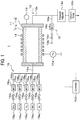
- FIG. 1 is a view schematically illustrating an outline of a configuration of a film forming apparatus according to a first embodiment.
- a film forming apparatus 1 in FIG. 1 includes a processing container 11 having a substantially rectangular parallelepiped shape.
- An exhaust line 12 is connected to the processing container 11, and the processing container 11 can be adjusted to a desired depressurized state (pressure) by the exhaust line 12.
- the exhaust line 12 has an exhaust pipe 12a having one end connected to the processing container 11.
- the exhaust pipe 12a includes an exhaust manifold or the like, and a vacuum pump 12b including a mechanical booster pump or the like is connected to a side opposite a side of the processing container.
- a pressure adjuster 12c which is configured to adjust the pressure in the processing container 11 and includes an automatic pressure control (APC) valve, a proportional control valve, or the like, is provided between the processing container 11 and the vacuum pump 12b.
- the processing container 11 is provided with a pressure gauge 13, and the pressure in the processing container 11 is adjusted by the pressure adjuster 12c based on a measurement result by the pressure gauge 13.
- the processing container 11 includes a processing container main body 11a having a hollow quadrangular columnar shape and having openings at opposite ends thereof, and side walls 11b connected to the opposite ends of the processing container main body 11a, respectively, so as to close the openings.
- An induction coil 14 connected to a radio frequency power supply 14a is provided outside the processing container main body 11a.
- the induction coil 14 heats a substrate to be processed.
- the induction coil 14 inductively heats a susceptor 23 to be described later or the like, and the substrate to be processed or the like is heated by radiant heat or heat conduction from the inductively heated susceptor 23.
- a processing gas supply mechanism 15 is configured to supply a processing gas, such as a raw material gas as a raw material for film formation, into the processing container 11.
- the processing gas supply mechanism 15 has a gas supply pipe 15a connected to the processing container 11 and gas supply pipes 15bi to 15bs connected to the gas supply pipe 15a.
- the gas supply pipes 15bi to 15bs are provided with mass flow controllers (MFC) 15c 1 to 15c 5 and valves 15d 1 to 15d 5 , respectively.
- MFC mass flow controllers
- a gas source 15e 1 is connected to the gas supply pipe 15b 1 , and SiH 4 gas is supplied from the gas source 15e 1 to the gas supply pipe 15b 1 .
- gas sources 15e 2 to 15e 5 are connected to the gas lines 15b 2 to 15b 5 , respectively, and C 3 H 8 gas, H 2 gas, ClF 3 gas, and Ar gas are supplied from the gas sources 15e 2 to 15e 5 to the gas supply pipes 15b 2 to 15b 5 , respectively.
- SiH 4 gas, C 3 H 8 gas, and H 2 gas are supplied from the gas supply pipes 15b 1 to 15b 3 to the processing container 11, respectively, as a raw material gas for film formation.
- one of H 2 gas, ClF 3 gas, and Ar gas from the gas supply pipes 15b 3 to 15b 5 , respectively, is supplied to the processing container 11, or two or more of these gases are mixed and supplied to the processing container 11.
- an air introduction mechanism 16 is connected to the exhaust pipe 12a at an upstream side of the pressure adjuster 12c in order to introduce the air into the processing container 11 during a cleaning process of the processing container 11.
- the air introduction mechanism 16 has a pipe 16a having one end connected to the exhaust pipe 12a and the other end having an air introduction port 16b formed therein.
- the pipe 16a is provided with a mass flow controller (MFC) 16c and a valve 16d in this order from a side of the exhaust pipe 12a.
- MFC mass flow controller
- a connection destination of the air introduction mechanism 16 is not limited to the exhaust pipe 12a as long as atmospheric atmosphere can be formed in the processing container 11.
- the pipe 16a is provided with a filter (not illustrated) in order to remove dust, dirt, and the like from the air.
- the film forming apparatus 1 includes a controller 100.
- the controller 100 is, for example, a computer, and has a program storage (not illustrated).
- the program storage stores programs for controlling the MFCs 15c 1 to 15c 5 , the valves 15d 1 to 15d 5 , the radio frequency power supply 14a, the pressure adjuster 12c, and the like to perform a film forming method.
- the programs may be recorded in a computer-readable storage medium, and may be installed on the controller 100 from the storage medium.
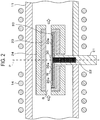
- FIG. 2 is a cross-sectional view schematically illustrating an outline of a configuration inside the processing container 11 in the film forming apparatus 1 of FIG. 1 .
- a lifter 22 configured to vertically move the holder 30 holding the substrate W, and the susceptor 23 having an internal space S accommodating therein the stage 20 and configured to be inductively heated by the induction coil 14 are provided.
- the stage 20 is formed in a disk shape having a recess 20a, which is formed in a top surface of the stage 20 and recessed downwards in a vertical direction, and is provided horizontally inside the processing container 11.
- the holder 30 is fit into the recess 20a.
- the holder 30 also rotates with a rotation of the stage 20 by the rotary shaft 21 about a central axis P of the stage 20 and the rotary shaft 21 by the rotary shaft 21.
- the stage 20 is formed of a conductive material, which has high heat resistance and is easily heated through induction heating, and is formed by, for example, a graphite member having a top surface thereof coated with SiC.
- One end of the rotary shaft 21 is connected to a lower center of the stage 20.
- the other end of the rotary shaft 21 penetrates and extends below a bottom of the processing container 11, and is connected to a rotational driving mechanism (not illustrated).
- the stage 20 rotates with a rotation of the rotary shaft 21 by the rotational driving mechanism.
- the lifter 22 serves to deliver the substrate W between a transfer device for the substrate W outside the film forming apparatus 1 and the stage 20. Specifically, the lifter 22 delivers the holder 30 holding the substrate W therebetween. By moving the lifter 22 vertically by a lifting driving mechanism (not illustrated), the holder 30 is moved vertically, and accordingly, the substrate W is also moved vertically.
- the susceptor 23 is formed in a rectangular parallelepiped shape having openings on two surfaces opposing each other, and has a structure in which a processing gas is supplied from the opening formed in one surface and the processing gas is discharged from the opening formed in the other surface.
- the processing gas is supplied and discharged along a direction orthogonal to the central axis P of the rotary shaft 21 and parallel to a processing target surface (a top surface in the drawing) of the substrate W placed on the stage 20.
- the susceptor 23 is formed of a conductive material, which has high heat resistance and is easily heated through induction heating, and is formed by, for example, a graphite member having a surface coated with SiC on a side of the substrate W.
- a heat insulator 24 that insulates the susceptor 23 and the processing container 11 from each other is provided.
- the heat insulator 24 is formed using, for example, a fibrous carbon material having a large porosity.
- a holding structure configured to hold the heat insulator 24 in a state in which the heat insulator 24 is spaced apart from the processing container 11 is provided outside the heat insulator 24.
- the holder 30 is a disk-shaped member having a diameter smaller than that of the stage 20, and is used for the purpose of collectively loading and unloading a plurality of substrates W into and from the film forming apparatus 1.
- the holder 30 can hold the plurality of substrates W.
- a plurality of placement regions 30a on which the substrates W are placed is formed on a top surface of the holder 30.
- the plurality of placement regions 30a is arranged at equal intervals in a circumferential direction with respect to a center of the holder 30, that is, the central axis P.
- the holder 30 is formed by a member having a surface formed by a pyrolytic carbon film, in other words, a member coated with pyrolytic carbon. More specifically, the holder 30 is formed by a graphite member having a surface, which includes the surface on which the substrates W are placed, coated with pyrolytic carbon.
- FIG. 3 is a view illustrating a flowchart for explaining an exemplary film forming method according to the first embodiment.
- the holder 30 holding substrates W is loaded into the processing container 11 (step S1). Specifically, the holder 30 is loaded into the processing container 11 from the outside of the film forming apparatus 1 via a gate valve (not illustrated) by a transfer device (not illustrated) outside the film forming apparatus 1, and is located above the stage 20. Subsequently, the lifter 22 is moved up, whereby the holder 30 is supported by the lifter 22. Subsequently, the transfer device is retracted from the inside of the processing container 11 and the lifter 22 is moved down, whereby the holder 30 is placed on the stage 20.
- a raw material gas as a processing gas and a carrier gas are supplied from the processing gas supply mechanism 15 to the processing container 11, and the substrates W held on the holder 30 are heated.
- a SiC film is formed on the substrates W through epitaxial growth (step S2).
- the valves 15d 1 to 15d 3 are opened, and SiH 4 gas, C 3 H 8 gas, and H 2 gas are supplied into the processing container 11 while flow rates thereof are adjusted by the MFCs 15c 1 to 15c 3 , respectively.
- radio frequency power is supplied from the radio frequency power supply 14a to the induction coil 14.
- the susceptor 23 and the stage 20 are inductively heated, and the substrates W are heated by radiation and heat conduction from the susceptor 23 and the stage 20.
- the SiC film is formed on the substrates W through epitaxial growth.
- a pressure in the processing container 11 is, for example, 10 Torr to 600 Torr
- the flow rates of the SiH 4 gas, the C 3 H 8 gas, and the H 2 gas are, for example, 10 to 600 sccm, 10 to 600 sccm, and 10 to 200 slm, respectively
- a temperature of the substrates W is, for example, 1,500 degrees C to 1,700 degrees C.
- N 2 gas may be added to the raw material gas in case of forming the SiC film as an n-type
- TMA trimethylaluminum
- the holder 30 holding the substrates W is unloaded from the processing container 11 (step S3). Specifically, after the valves 15d 1 to 15d 3 are closed and the supply of the raw material gas is stopped, the lifter 22 is moved up to raise the holder 30 on which the substrates W are supported. Then, the transfer device outside the film forming apparatus 1 is inserted into the processing container 11 via the gate valve and is located below the holder 30. Thereafter, by moving the lifter 22 down, the holder 30 is delivered from the lifter 22 to the transfer device, and by retracting the transfer device from the processing container 11, the holder 30 holding the substrates W is unloaded from the processing container 11.
- the supply of the radio frequency power to the induction coil 14 may be cut off. However, it is desirable to supply the radio frequency power to the induction coil 14 such that temperatures of the stage 20 and the susceptor 23 are controlled to be an optimal values for a subsequent process.
- a SiC film having a desired thickness is formed on the substrates W.
- a holder 30 that does not hold a substrate W is loaded into the processing container 11 and is placed on the stage 20 (step S4). Since the specific processing is the same as that in step S1, a description thereof is omitted.
- the holder 30 loaded in step S4 may hold dummy substrates having the same shape as that of the substrates W.
- ClF 3 gas is supplied into the processing container 11 and unnecessary reaction products adhered to parts other than the substrates W during the film forming process are removed (step S5). Specifically, the valves 15d 4 and 15ds are opened, and ClF 3 gas as a fluorine-containing gas and Ar gas for dilution are supplied into the processing container 11 while flow rates thereof are adjusted by the MFCs 15c 4 and 15c 5 , respectively. As a result, the unnecessary reaction products are removed. That is, a cleaning process is performed.
- the pressure in the processing container 11 is, for example, 10 Torr to 100 Torr
- the flow rate of ClF 3 gas is, for example, 100 to 2,000 sccm
- the temperature of the susceptor 23 is, for example, 400 degrees C to 600 degrees C.
- the ClF 3 gas is discharged from the processing container 11 (step S6). Specifically, the valve 15d 4 is closed with the valve 15ds in the open state, and Ar gas is supplied into the processing container 11 while the flow rate thereof is adjusted by the MFC 15c 5 . As a result, the ClF 3 gas in the processing container 11 is discharged.
- the air is introduced into the processing container 11, whereby substances, which remain in the processing container 11 after the cleaning process using the ClF 3 gas and need to be removed, that is, impurities unnecessary for a subsequent film forming process and substances causing defects (hereinafter referred to as "residues") are removed (step S7).
- the valve 15ds is closed and the valve 16 d is opened, and the air is introduced into the processing container 11 while the flow rate thereof is adjusted by the MFC 16c.
- the pressure in the processing container 11 is controlled to be, for example, 10 kPa to 65 kPa, and the introduction of the air is performed for 0.5 to 2.0 hours.
- H 2 gas is supplied into the processing container 11 and a hydrogen annealing process is performed (step S8). Specifically, the valve 16d is closed and the valve 15d 3 is opened, and H 2 gas is supplied into the processing container 11 while the flow rate thereof is adjusted by the MFC 15c 3 .
- radio frequency power is supplied from the radio frequency power supply 14a to the induction coil 14, so that the susceptor 23 and the like are heated.
- a C x F y film and carbon particles which are reaction products of pyrolytic carbon and the ClF 3 gas and are formed on the surface of the holder 30 during the process of removing the reaction products using the ClF 3 gas, are removed.
- substances which have not been removed in the process of removing the reaction products and in the process of removing the residues, are removed.
- the flow rate of the H 2 gas is, for example, 10 to 200 slm
- the temperature of the susceptor 23 is, for example, 1,500 degrees C or higher.
- the hydrogen annealing process is performed for 0.5 to 2.0 hours. A time required for the hydrogen annealing process can be shortened by increasing the temperature of the susceptor 23.
- a raw material gas is supplied into the processing container 11 at a low C/Si ratio, and a SiC film is formed on the surface of the holder 30.
- the surface of the holder 30 is coated with SiC (step S9).
- the valves 15d 3 maintained in the open state, the valves 15d 1 and 15d 2 are opened and flow rates are adjusted by the MFCs 15c 1 and 15c 2 , whereby SiH4 gas, C 3 H 8 gas, and H 2 gas are supplied into the processing container 11.
- a SiC film of about 5 to 10 ⁇ m is formed on the surface of the holder 30 on which the substrates W are to be placed.
- the surfaces of the susceptor 23 or the stage 20 are coated with SiC.
- the pressure in the processing container 11 is, for example, 10 Torr to 600 Torr
- the flow rates of the SiH 4 gas, the C 3 H 8 gas, and the H 2 gas are, for example, 10 to 600 sccm, 10 to 600 sccm, and 100 to 150 slm, respectively
- the temperature of the susceptor 23 is, for example, 1,600 degrees C to 1,700 degrees C.
- the flow rates of the SiH 4 gas and the C 3 H 8 gas are adjusted such that the C/Si ratio becomes 0.5, for example, for the first few minutes, and subsequently, the flow rate of the C 3 H 8 gas is increased such that the C/Si ratio becomes 0.8.
- a SiC film having a desired film thickness can be formed on the surface of the holder 30 or the like by maintaining the supply of the SiH4 gas and the C 3 H 8 gas for, for example, 30 minutes.
- the C/Si ratio at the start of the SiC film formation is low, for example, 0.5, as described above, it is possible to enhance adhesion of pyrolytic carbon of the holder 30 and the SiC film formed in the coating process.
- the flow rates of the SiH 4 gas and the C 3 H 8 gas are adjusted such that the C/Si ratio is 1.0 to 1.4.
- step S10 After coating the SiC, the holder 30, which does not hold substrates W and has been coated with SiC, is unloaded from the processing container 11 (step S10). Since the specific processing is the same as that in step S3, a description thereof is omitted.
- step S10 the process is returned to step S1, and the holder 30 on which substrates W are placed is loaded into the processing container 11, and the processes of steps S1 to S10 are repeated.
- the surface of the holder 30 is pre-coated with SiC through the same process as in step S9 in advance.
- the holder 30 is placed on the stage 20, and the surface of the holder 30 is formed by pyrolytic carbon having higher resistance to the ClF 3 gas compared to SiC. Therefore, it is possible to extend the lifespan of the holder 30, which is used in both the cleaning process using ClF 3 gas and the film forming process. Since pyrolytic carbon has also high heat resistance, the holder 30 can be used in a high-temperature process. In addition, in the present embodiment, since the surface of the holder 30 is formed by pyrolytic carbon, ClF 3 gas is not consumed by reaction with the surface of the holder 30 during the cleaning process using ClF 3 gas. Therefore, it is possible to improve efficiency of the cleaning process using ClF 3 gas.
- the raw material gas of the SiC film is supplied at a low C/Si ratio, and the SiC film is formed (pre-coated) on the surface of the holder 30.
- the holder 30 is not pre-coated with a SiC film is considered.
- SiC which has been adhered to the holder 30 in a powder form during the film forming process using the holder 30, may peel off from the holder 30 and may cause defects.
- the SiC film is pre-coated on the holder 30 with good adhesion. Since the SiC on the holder 30 does not peel off from the holder 30 due to the good adhesion between the pre-coated film and pyrolytic carbon, it is possible to suppress occurrence of defects.
- a C x F y film which is a reaction product of the pyrolytic carbon of the holder 30 and the ClF 3 gas, is removed from the surface of the holder 30.
- the C x F y film is not removed unlike the present embodiment, when the SiC film is formed or pre-coated by using the holder 30 from which no C x F y film has been removed, the C x F y film peels off due to film stress or the like, which may cause defects.
- the C x F y film since the C x F y film is removed as described above, occurrence of defects caused by the C x F y film can be suppressed.
- the holder 30 is configured by a member having a surface formed of pyrolytic carbon, a C x F y film is formed during the cleaning process using ClF 3 gas.
- the C x F y film can be removed through the hydrogen annealing process in the film forming apparatus 1.
- the cleaning process using ClF 3 gas, removing the reaction products of ClF 3 gas and the holder 30, and the pre-coating SiC on the holder 30 may be continuously performed.
- pre-coating the SiC film on the holder 30 is performed in parallel with coating surfaces of the susceptor 23 and the stage 20 with SiC, which is an existing process.
- removing the C x F y film is also performed in parallel with a process of removing substances that have not be removed in the process of removing reaction products and the process of removing residues, which are existing processes. That is, the film forming method according to the present embodiment does not require additional processes.
- ClF 3 gas is supplied into the processing container 11 after the film forming process, it is possible to remove a wide variety of unnecessary reaction products in the film forming apparatus 1.
- only the susceptor 23 and the stage 20 are selectively heated through induction heating. Therefore, it is possible to remove deposits having different characteristics at the same time with a single process, for example, by removing, at a high temperature, rigid 3C-SiC polycrystals grown on the stage 20 and removing, at a low temperature, deposits that easily react with ClF 3 gas, such as Si and Si-rich dendritic products adhered to the vicinity of the gas introduction port of the susceptor 23 and SiH x adhered to the exhaust pipe 12a.
- the air is introduced into the processing container 11 to remove the residues.
- the residues react with moisture in the air and are discharged from the processing container 11.
- substances that cannot be removed through the process of removing the residues by introducing the air are removed through the hydrogen annealing process.
- Test Piece 1 graphite test piece having a surface coated with pyrolytic carbon
- Test Piece 2 graphite test piece having a surface coated with SiC
- a mass of Test Piece 1 was 45.282 g before exposure and 45.277 g after exposure, and a mass change rate was 1.0 ⁇ 10 -4 g/cm 2 .
- a mass of Test Piece 2 was 9.732 g before the exposure and 9.198 g after the exposure, and a mass change rate was 6.8 ⁇ 10 -3 g/cm 2 .
- pyrolytic carbon has a resistance to ClF 3 gas about 70 times higher than that of SiC.
- Test Piece 1 a test, in which an exposure process to ClF 3 gas, a hydrogen annealing process similar to that in step S8, a SiC coating process similar to that in step S9, a SiC film forming process similar to that in step S2, and an exposure process to ClF 3 gas were sequentially performed, was conducted and a change in weight was examined. At that time, the surface of Test Piece 1 was observed by an optical microscope. A SiC film having a thickness of about 150 ⁇ m was formed by repeatedly performing a SiC film forming process similar to that in steps S1 to S3.
- the mass of Test Piece 1 was 45.263 g in an initial state before the exposure process to ClF 3 gas, 48.219 g after the SiC film forming process, and 45.284 g after the final exposure process to ClF 3 gas.
- the surface of Test Piece 1 returned to the initial state (the state before the first exposure process to ClF 3 gas). From this result, it can be confirmed that only the SiC film was etched in Test Piece 1 during the final exposure process to ClF 3 gas.
- ClF 3 gas is not consumed when etching of a base material of the holder 30. Since the ClF 3 gas that is not consumed is used for cleaning the susceptor 23, utilization efficiency of ClF 3 gas can be improved.
- the holder 30 is formed by a graphite member having a surface coated with pyrolytic carbon.
- the holder 30 is formed by a bulk material of pyrolytic carbon.
- Other components of the film forming apparatus 1 and the film forming method including the cleaning process in the present embodiment are the same as those in the first embodiment.
- the present embodiment has the following effects in addition to the effects of the first embodiment.
- the holder 30 of the present embodiment has high resistance to stress generated between the holder 30 and the SiC film formed during the pre-coating or film forming process, and thus warpage due to the above-mentioned stress does not occur. Therefore, the holder 30 of the present embodiment is more suitable for the film formation than that of the first embodiment.
- the bulk material of pyrolytic carbon has anisotropy in thermal conductivity and has thermal conductivities of 345 W/mk (in a plane direction at room temperature) and 1.7 W/mk (in a thickness direction at room temperature). Therefore, heat conducted from the susceptor 23 and the stage 20 is made uniform in a plane by the holder 30 of the present embodiment, and is transferred to the substrates W. Therefore, according to the present embodiment, it is possible to improve in-plane uniformity of a temperature distribution of the substrates W.
- the in-plane uniformity of the temperature distribution of the substrates W As described above, it is possible to reduce the number of defects in a SiC film formed on the substrates W. The reason is that, triangular defects and the like are likely to occur in a low-temperature portion, but by improving the in-plane uniformity of the temperature distribution of the substrates W, it is possible to prevent low-temperature portions from being generated in the substrates W. In addition, the low-temperature portions are likely to occur in portions of the substrates W located on an outer circumferential portion of a stage 20.
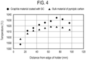
- the maximum temperature difference of the substrates W among inner and outer portions of the holder was about 50 degrees C, which is large.
- the maximum temperature difference of the substrates W among inner and outer portions of the holder was about 20 degrees C, which is small.
- the film forming apparatus of the present embodiment is capable of improving the in-plane uniformity of the temperature distribution of the substrates W.
- FIG. 5 is a partial cross-sectional view schematically illustrating an outline of a holder 30 included in the film forming apparatus according to the third embodiment.
- the holder 30 has a flange 31 on an outer circumference thereof.
- the flange 31 covers a gap D between a side wall defining the recess 20a and the holder 30 when the holder 30 is placed in the recess 20a of the stage 20.
- the flange 31 since the flange 31 is provided, it is possible to prevent generation of particles due to the SiC that has entered the gap D.
- the holder 30 are commonly used during of the film forming process and during the cleaning process.
- the plate-shaped member placed on the stage 20 during the cleaning process also served as a holder during the film forming process.
- a plate-shaped member configured in the same manner as the holder 30 of each of the embodiments described above may be used only during the cleaning process, and a holder formed by, for example, a graphite member having a surface coated with SiC may be used during the film forming process.
- the plate-shaped member placed on the stage 20 during the cleaning process also serves as a holder during the film forming process, the following effects can be achieved.
- the "plate-shaped member configured in the same manner as the holder 30 of each of the embodiments" described above is specifically, for example, a graphite member having a surface coated with pyrolytic carbon or a plate-shaped member formed by a bulk material of pyrolytic carbon, and is a member having substantially the same shape as the holder 30.
- the stage 20 and the susceptor 23 are formed by a graphite member coated with SiC.
- the stage 20 or the susceptor 23 may be formed by a graphite member having a surface coated with pyrolytic carbon. As a result, the lifespans of the stage 20 and the susceptor 23 can be extended.
- the hydrogen annealing process of step S8 and the pre-coating process of step S9 are performed after the process of removing residues by introducing the air in step S7, but may be performed before the process of removing residues.
- ClF 3 gas is used to remove unnecessary reaction products adhered during the film forming process, but other fluorine-containing gases, such as ClF gas and ClF 5 gas, may be used.
- the raw material gas supplied onto the substrates W are supplied and discharged along a direction parallel to the substrates W.
- each of the above embodiments is also applicable to film formation using a film forming apparatus in which a raw material gas is supplied along a direction perpendicular to the substrates W.
- the fluorine-containing gas is not consumed by a reaction with the plate-shaped member. Thus, it is possible to improve efficiency of cleaning using the fluorine-containing gas.
- the fluorine-containing gas is not consumed by a reaction with the plate-shaped member formed by pyrolytic carbon, it is possible to suppress a total flow rate of a cleaning gas using the fluorine-containing gas, and to suppress damage to members on an upstream side of the stage. Therefore, the lifespans of the members on the upstream side can be extended.
- the film forming method set forth in (1) or (2), wherein the forming the silicon carbide film includes forming the silicon carbide film by using the holder having a surface formed by silicon carbide.
- the SiC formed on the plate-shaped member during the film formation does not peel off from the plate-shaped member.
- a film forming apparatus for forming a silicon carbide film on a substrate to be processed including:
- 1 film forming apparatus
- 2 processing container
- 15 processing gas supply mechanism
- 20 stage
- 30 holder
- W substrate.
Landscapes
- Chemical & Material Sciences (AREA)
- Engineering & Computer Science (AREA)
- Materials Engineering (AREA)
- Metallurgy (AREA)
- Organic Chemistry (AREA)
- General Chemical & Material Sciences (AREA)
- Chemical Kinetics & Catalysis (AREA)
- Mechanical Engineering (AREA)
- Inorganic Chemistry (AREA)
- Crystallography & Structural Chemistry (AREA)
- Chemical Vapour Deposition (AREA)
- Crystals, And After-Treatments Of Crystals (AREA)
Applications Claiming Priority (2)
| Application Number | Priority Date | Filing Date | Title |
|---|---|---|---|
| JP2019017111A JP7153582B2 (ja) | 2019-02-01 | 2019-02-01 | 成膜方法及び成膜装置 |
| PCT/JP2020/002735 WO2020158656A1 (ja) | 2019-02-01 | 2020-01-27 | 成膜方法及び成膜装置 |
Publications (2)
| Publication Number | Publication Date |
|---|---|
| EP3919657A1 true EP3919657A1 (de) | 2021-12-08 |
| EP3919657A4 EP3919657A4 (de) | 2022-10-05 |
Family
ID=71841025
Family Applications (1)
| Application Number | Title | Priority Date | Filing Date |
|---|---|---|---|
| EP20749081.4A Pending EP3919657A4 (de) | 2019-02-01 | 2020-01-27 | Filmausbildungsverfahren und filmausbildungsvorrichtung |
Country Status (5)
| Country | Link |
|---|---|
| US (1) | US12065732B2 (de) |
| EP (1) | EP3919657A4 (de) |
| JP (1) | JP7153582B2 (de) |
| KR (1) | KR102652637B1 (de) |
| WO (1) | WO2020158656A1 (de) |
Families Citing this family (3)
| Publication number | Priority date | Publication date | Assignee | Title |
|---|---|---|---|---|
| JP7585734B2 (ja) * | 2020-11-20 | 2024-11-19 | 株式会社レゾナック | サセプタ及び化学的気相成長装置 |
| JP7790831B2 (ja) * | 2022-03-07 | 2025-12-23 | 東京エレクトロン株式会社 | 基板加熱装置及び基板処理装置 |
| WO2025136086A1 (en) * | 2023-12-22 | 2025-06-26 | Schunk Xycarb Technology B.V. | Cleaning method for removing parasitic grown silicon carbides and an interior part of an epitaxy process chamber and an epitaxy process system |
Family Cites Families (18)
| Publication number | Priority date | Publication date | Assignee | Title |
|---|---|---|---|---|
| JP3061455B2 (ja) * | 1991-09-04 | 2000-07-10 | 株式会社東芝 | 気相成長装置及び気相成長装置内のクリーニング方法 |
| US7288284B2 (en) * | 2004-03-26 | 2007-10-30 | Taiwan Semiconductor Manufacturing Co., Ltd. | Post-cleaning chamber seasoning method |
| JP4619036B2 (ja) * | 2004-05-10 | 2011-01-26 | イビデン株式会社 | 炭素複合部材 |
| JP5283370B2 (ja) * | 2007-11-29 | 2013-09-04 | 株式会社ニューフレアテクノロジー | 気相成長装置および気相成長方法 |
| JP5144328B2 (ja) * | 2008-03-24 | 2013-02-13 | 大陽日酸株式会社 | 気相成長装置 |
| JP5542560B2 (ja) * | 2010-07-20 | 2014-07-09 | 株式会社ニューフレアテクノロジー | 半導体製造装置およびサセプタのクリーニング方法 |
| JP5698043B2 (ja) | 2010-08-04 | 2015-04-08 | 株式会社ニューフレアテクノロジー | 半導体製造装置 |
| JP5763477B2 (ja) * | 2011-08-26 | 2015-08-12 | 大陽日酸株式会社 | 炭化珪素成膜装置、及び炭化珪素除去方法 |
| US8940614B2 (en) * | 2013-03-15 | 2015-01-27 | Dow Corning Corporation | SiC substrate with SiC epitaxial film |
| JP2015002292A (ja) * | 2013-06-17 | 2015-01-05 | 東京エレクトロン株式会社 | 化合物半導体膜成膜用基板の移載装置および移載方法、ならびに化合物半導体膜の成膜システムおよび成膜方法 |
| JP6172669B2 (ja) * | 2013-08-22 | 2017-08-02 | 大陽日酸株式会社 | サセプタ、及びサセプタのクリーニング方法 |
| JP6257075B2 (ja) * | 2013-12-19 | 2018-01-10 | 昭和電工株式会社 | SiCエピタキシャルウェハの製造方法 |
| JP6393161B2 (ja) | 2014-11-21 | 2018-09-19 | 東京エレクトロン株式会社 | 成膜装置 |
| WO2016113924A1 (ja) * | 2015-01-13 | 2016-07-21 | 住友電気工業株式会社 | 半導体積層体 |
| JP6541257B2 (ja) * | 2015-06-22 | 2019-07-10 | 昭和電工株式会社 | 炭化珪素膜の成膜装置のクリーニング方法 |
| CN109478510A (zh) | 2016-08-31 | 2019-03-15 | 国立大学法人横滨国立大学 | 半导体制造用反应室的清洗方法 |
| JP6841321B2 (ja) * | 2017-04-06 | 2021-03-10 | 三菱電機株式会社 | SiCエピタキシャルウエハの製造方法 |
| WO2018193664A1 (ja) * | 2017-04-18 | 2018-10-25 | 東京エレクトロン株式会社 | 成膜装置及びそのクリーニング方法 |
-
2019
- 2019-02-01 JP JP2019017111A patent/JP7153582B2/ja active Active
-
2020
- 2020-01-27 WO PCT/JP2020/002735 patent/WO2020158656A1/ja not_active Ceased
- 2020-01-27 KR KR1020217026300A patent/KR102652637B1/ko active Active
- 2020-01-27 EP EP20749081.4A patent/EP3919657A4/de active Pending
- 2020-01-27 US US17/425,581 patent/US12065732B2/en active Active
Also Published As
| Publication number | Publication date |
|---|---|
| JP2020126883A (ja) | 2020-08-20 |
| JP7153582B2 (ja) | 2022-10-14 |
| US20220098726A1 (en) | 2022-03-31 |
| KR20210113383A (ko) | 2021-09-15 |
| KR102652637B1 (ko) | 2024-04-01 |
| EP3919657A4 (de) | 2022-10-05 |
| US12065732B2 (en) | 2024-08-20 |
| WO2020158656A1 (ja) | 2020-08-06 |
Similar Documents
| Publication | Publication Date | Title |
|---|---|---|
| CN103649385B (zh) | SiC外延晶片及其制造方法、以及SiC外延晶片的制造装置 | |
| EP2549522A1 (de) | Herstellungsverfahren für halbleiterdünnschichten, vorrichtung zur herstellung von halbleiterdünnschichten, suszeptor und suszeptorenwerkzeug | |
| US11390944B2 (en) | Film-forming device and method for cleaning same | |
| WO2012029661A1 (ja) | 半導体装置の製造方法及び基板処理装置 | |
| US12065732B2 (en) | Film forming method and film forming apparatus | |
| US11482416B2 (en) | Vapor phase growth method | |
| JP2018186252A (ja) | エピタキシャル成長装置及びエピタキシャル成長方法 | |
| TWI734286B (zh) | 成膜方法、成膜裝置、基座單元及用於基座單元的墊片組 | |
| EP3726563A1 (de) | Filmbildungsvorrichtung | |
| CN100468631C (zh) | 衬托器 | |
| CN107771226B (zh) | 晶片上进行外延生长的反应器重启动的准备方法 | |
| KR102492343B1 (ko) | 성막 장치 및 성막 방법 | |
| CN221822394U (zh) | 用于碳化硅衬底的感应式加热外延炉 | |
| CN117265654A (zh) | 一种外延生长方法及外延晶圆 | |
| CN118186575A (zh) | 用于碳化硅衬底的感应式加热外延炉及外延生长方法 | |
| JP2005166916A (ja) | 半導体装置の製造方法 |
Legal Events
| Date | Code | Title | Description |
|---|---|---|---|
| STAA | Information on the status of an ep patent application or granted ep patent |
Free format text: STATUS: THE INTERNATIONAL PUBLICATION HAS BEEN MADE |
|
| PUAI | Public reference made under article 153(3) epc to a published international application that has entered the european phase |
Free format text: ORIGINAL CODE: 0009012 |
|
| STAA | Information on the status of an ep patent application or granted ep patent |
Free format text: STATUS: REQUEST FOR EXAMINATION WAS MADE |
|
| 17P | Request for examination filed |
Effective date: 20210820 |
|
| AK | Designated contracting states |
Kind code of ref document: A1 Designated state(s): AL AT BE BG CH CY CZ DE DK EE ES FI FR GB GR HR HU IE IS IT LI LT LU LV MC MK MT NL NO PL PT RO RS SE SI SK SM TR |
|
| DAV | Request for validation of the european patent (deleted) | ||
| DAX | Request for extension of the european patent (deleted) | ||
| RAP3 | Party data changed (applicant data changed or rights of an application transferred) |
Owner name: TOKYO ELECTRON LIMITED |
|
| RIN1 | Information on inventor provided before grant (corrected) |
Inventor name: KOBAYASHI, HIROKATSU Inventor name: NAKAMURA, MICHIKAZU Inventor name: SANO, YUKIO Inventor name: HARASHIMA, MASAYUKI |
|
| A4 | Supplementary search report drawn up and despatched |
Effective date: 20220905 |
|
| RIC1 | Information provided on ipc code assigned before grant |
Ipc: H01L 21/02 20060101ALI20220830BHEP Ipc: C23C 16/44 20060101ALI20220830BHEP Ipc: C23C 16/32 20060101ALI20220830BHEP Ipc: C30B 29/36 20060101ALI20220830BHEP Ipc: C30B 25/12 20060101AFI20220830BHEP |