EP3919661A1 - Webmaschine - Google Patents
Webmaschine Download PDFInfo
- Publication number
- EP3919661A1 EP3919661A1 EP21176608.4A EP21176608A EP3919661A1 EP 3919661 A1 EP3919661 A1 EP 3919661A1 EP 21176608 A EP21176608 A EP 21176608A EP 3919661 A1 EP3919661 A1 EP 3919661A1
- Authority
- EP
- European Patent Office
- Prior art keywords
- driving
- shaft
- force transmission
- braking
- force
- Prior art date
- Legal status (The legal status is an assumption and is not a legal conclusion. Google has not performed a legal analysis and makes no representation as to the accuracy of the status listed.)
- Granted
Links
Images
Classifications
-
- D—TEXTILES; PAPER
- D03—WEAVING
- D03D—WOVEN FABRICS; METHODS OF WEAVING; LOOMS
- D03D49/00—Details or constructional features not specially adapted for looms of a particular type
- D03D49/02—Construction of loom framework
-
- D—TEXTILES; PAPER
- D03—WEAVING
- D03D—WOVEN FABRICS; METHODS OF WEAVING; LOOMS
- D03D51/00—Driving, starting, or stopping arrangements; Automatic stop motions
-
- D—TEXTILES; PAPER
- D03—WEAVING
- D03C—SHEDDING MECHANISMS; PATTERN CARDS OR CHAINS; PUNCHING OF CARDS; DESIGNING PATTERNS
- D03C13/00—Shedding mechanisms not otherwise provided for
- D03C13/02—Shedding mechanisms not otherwise provided for with independent drive motors
-
- D—TEXTILES; PAPER
- D03—WEAVING
- D03D—WOVEN FABRICS; METHODS OF WEAVING; LOOMS
- D03D49/00—Details or constructional features not specially adapted for looms of a particular type
- D03D49/60—Construction or operation of slay
-
- D—TEXTILES; PAPER
- D03—WEAVING
- D03D—WOVEN FABRICS; METHODS OF WEAVING; LOOMS
- D03D49/00—Details or constructional features not specially adapted for looms of a particular type
- D03D49/60—Construction or operation of slay
- D03D49/62—Reeds mounted on slay
-
- D—TEXTILES; PAPER
- D03—WEAVING
- D03D—WOVEN FABRICS; METHODS OF WEAVING; LOOMS
- D03D51/00—Driving, starting, or stopping arrangements; Automatic stop motions
- D03D51/007—Loom optimisation
-
- D—TEXTILES; PAPER
- D03—WEAVING
- D03D—WOVEN FABRICS; METHODS OF WEAVING; LOOMS
- D03D51/00—Driving, starting, or stopping arrangements; Automatic stop motions
- D03D51/02—General arrangements of driving mechanism
-
- D—TEXTILES; PAPER
- D03—WEAVING
- D03D—WOVEN FABRICS; METHODS OF WEAVING; LOOMS
- D03D51/00—Driving, starting, or stopping arrangements; Automatic stop motions
- D03D51/06—Driving, starting, or stopping arrangements; Automatic stop motions using particular methods of stopping
Definitions
- the present invention relates to a loom including a driving shaft to which a main shaft of the loom is connected and to which a swing shaft for driving a reed to swing is connected via a swing mechanism, a driving motor to which the driving shaft is connected via a driving-force transmission mechanism to rotationally drive the driving shaft, an opening device that is driven by the driving motor, a braking device that applies a brake to the main shaft, and a side frame that accommodates the driving shaft and the swing shaft in an orientation in which each axial direction of the driving shaft and the swing shaft matches with a width direction.
- a loom has a shaft (driving shaft) of which one end is connected a main shaft and which is rotationally driven by a driving motor.
- the driving shaft is accommodated in one of a pair of side frames in a frame of the loom.
- the driving shaft is rotationally driven by the driving motor, so that the main shaft connected to the driving shaft is rotationally driven.
- the rotation of the driving shaft is also for driving the reed to swing.
- a swing shaft for driving the reed to swing is also accommodated in the one side frame, and the swing shaft is connected to the driving shaft via a swing mechanism such as a cam mechanism and a crank mechanism.
- the loom is configured such that the swing shaft is swing-driven as the driving shaft is rotationally driven, whereby the reed is driven to swing.
- JP-A-H5-156551 the configuration (driving-force transmission mechanism) that connects the driving shaft and the driving motor for rotationally driving the driving shaft by the driving motor is disclosed in JP-A-H5-156551 .
- an intermediate shaft which is connected to the driving motor by a pulley and a timing belt, is provided between the driving shaft to which a swing mechanism is connected and the driving motor.
- the intermediate shaft and the driving shaft are connected by a gear train.
- the loom includes an opening device that displaces a heddle frame in a vertical direction in order to give an opening motion to the warps.
- the opening device is provided in a form of being connected to the driving shaft so as to use the driving motor as a driving source, except for a type driven by a dedicated motor. Therefore, in such a loom, the driving motor and the opening device are connected to the driving shaft.
- the opening device is connected to the intermediate shaft connected to the driving motor in the form described above. That is, in the configuration of the related art, the driving motor and the opening device are connected to the driving shaft via the intermediate shaft and a gear train.
- the loom includes a braking device for applying a brake to the main shaft.
- the braking device is connected to the other end of the driving shaft and is configured to apply a brake to the main shaft by apply a brake to the driving shaft.
- the inertia force due to the brake of the opening device is further increased. Since the driving force of the driving motor that drives the opening device is also further increased, the inertia force in accordance with the brake of the driving motor is also further increased. Therefore, in such a case, the load applied to the gear train is further increased as described above during braking by the braking device, so that the damage thereof or the like is more likely to occur.
- connection configuration for connecting the driving shaft and the intermediate shaft a combination of a pulley and a timing belt can be considered in addition to the gear train.
- a load corresponding to the inertia force is applied to the timing belt connecting the driving shaft and the intermediate shaft.
- the timing belt may be damaged or the like.
- an object of the present invention is to provide a structure of a loom in which damage of the above-mentioned connection configuration can be prevented as much as possible during braking by a braking device.
- the present invention provides the loom as described above, in which the driving-force transmission mechanism includes a driving-force transmission shaft that is provided so as to protrude from a side wall of the side frame while extending parallel to the driving shaft within a space of the side frame, the driving-force transmission shaft being connected to the driving motor, and to which the opening device is connected, and a transmission mechanism that connects the driving-force transmission shaft and the driving shaft, and the braking device is connected to the driving transmission shaft.
- a load applied to the connection configuration that connects the driving shaft and the driving-force transmission shaft is small during braking by the braking device. More specifically, during the braking, the brake is applied to the driving shaft and the driving transmission shaft. Therefore, an inertia force due to the brake of connected configuration elements acts on each of the driving shaft and the driving transmission shaft.
- the driving-force transmission shaft is connected to the driving motor and the opening device as the configuration elements.
- the driving shaft is connected to the main shaft, a beating device, and the like as the configuration elements.
- connection configuration in a case of a configuration in which one or more configuration elements are connected to each other and the braking device is connected to one of two shafts connected to each other by the connection configuration, a brake is directly applied to one shaft (braking shaft) by the braking device, and thereby the other shaft (braked shaft) receives the braking force via the connection configuration.
- the connection configuration becomes a portion acting the braking force by the braking shaft on the braked shaft.
- the inertia force due to the configuration elements acting on each shaft as the brake is applied to each shaft naturally acts in a rotational direction of the shaft. Therefore, on the braking shaft side, the inertia force acts in a direction of weakening the braking force of the braking device. Therefore, the braking force, which is acted on the connection configuration by the braking shaft, is a force weakened by the inertia force acting on the braking shaft side by the braking force that the braking device tries to act on the braking shaft.
- the inertia force acting on the braked shaft is a force against the braking force (braking force that the braking shaft acts on the connection configuration) that the braked shaft receives from the connection configuration.
- the greater the inertia force acting on the braking shaft (the smaller the braking force that braking shaft acts on the connection configuration), the smaller load is applied to the connection configuration.
- the greater the inertia force acting on the braked shaft (the greater the force against the braking force received from the connection configuration), the greater the load is applied to the connection configuration.
- the inertia force acting on the shaft (driving transmission shaft) by the driving motor and the opening device is generally greater than the inertia force acting on the shaft (driving shaft) by the main shaft, the beating device, or the like. Therefore, compared with the configuration of the related art in which the driving shaft is the braking shaft, the load applied to the connection configuration during the braking is small in the configuration of the present invention in which the driving-force transmission shaft is the braking shaft. Therefore, according to the present invention, damage to the connection configuration is prevented as much as possible.
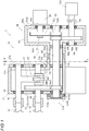
- a frame 10 includes a pair of housing-shaped side frames 12 and 12, and the side frames 12 are configured to be connected by a plurality of beam materials.
- the loom 1 includes a driving motor 20, and is configured to drive a main shaft 5 of the loom 1 by the driving motor 20.
- the driving motor 20 is provided on one side frame 12 (hereinafter, referred to as "driving-side frame") side of the pair of side frames 12 and 12.
- the driving-side frame 12 is configured of a frame body 14 that is a main portion, and a frame cover 16 attached to the frame body 14.
- the frame body 14 is formed in a housing shape having a space therein, and a portion (portion corresponding to a swing mechanism 60 or the like described later in a width direction) in a side wall (outer wall portion) 14a, which is an outside in the width direction of the loom 1, is open.
- the frame cover 16 is a member formed in a plate shape, and has a size capable of covering an opened portion (opening portion) 14c of the frame body 14.
- the driving-side frame 12 is configured such that the frame cover 16 is attached to the frame body 14 in a form of covering the opening portion 14c.
- the side wall (outer wall) 12a of the driving-side frame 12 that is the outside in the width direction is configured of the outer wall portion 14a of the frame body 14 and the frame cover 16 that covers the opening portion 14c thereof.
- the frame cover 16 is attached to the frame body 14 by using screw members (not illustrated) such as bolts, and the frame cover 16 can be attached or detached to or from the frame body 14.
- the loom 1 includes a driving shaft 30 which is interposed between a driving motor 20 and a main shaft 5, is rotationally driven by the driving motor 20, and rotationally drives the main shaft 5.
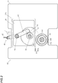
- the loom 1 includes a swing shaft 50 for driving a locking shaft 44 to swing in a beating device 40, and a swing mechanism 60 for connecting the swing shaft 50 and the driving shaft 30.
- the present example is an example in which a crank mechanism is adopted as the swing mechanism 60.
- the driving shaft 30, the swing shaft 50, and the swing mechanism 60 are disposed to be located within a range of the opening portion 14c in the driving-side frame 12 as viewed in the width direction, and are accommodated in the space within the driving-side frame 12. Details of each configuration in such a loom 1 are as follows.
- the driving shaft 30 is formed as a shaft having a dimension (length dimension) in an axial direction, which is larger than a dimension of the driving-side frame 12 in the width direction.
- the driving shaft 30 is a crank-shaped shaft formed as an eccentric portion 32 of which an intermediate portion is eccentric with respect to portions of both sides (both-side portions).
- the driving shaft 30 is rotatably supported by both side walls 12a and 12b of the driving-side frame 12 via bearings in an orientation in which the axial direction matches with the width direction, and is accommodated in the driving-side frame 12 in such a form.
- the support position is located such that the driving shaft 30 is located below an intermediate portion in the opening portion 14c in the frame body 14 when the driving-side frame 12 is viewed in the width direction.
- the driving shaft 30 is supported by the frame cover 16 at one end thereof in one end side. Therefore, the driving shaft 30 is in a state where a portion including the other end is provided in a form of protruding, on the other end side, from an inner wall (inner wall portion) 14b of the frame body 14 in the width direction.
- the driving shaft 30 is supported by the inner wall portion of the frame body 14 at a portion on the driving-side frame 12 side from the protruding portion.
- the main shaft 5 is connected to the other end of the driving shaft 30 by a coupling member 70.
- the swing shaft 50 is formed as a shaft of which a dimension is larger than the dimension of the driving-side frame 12 in the width direction. Similar to the driving shaft 30, the swing shaft 50 is supported by the both side walls 12a and 12b of the driving-side frame 12 via bearings in the orientation parallel to the driving shaft 30, and is accommodated in the driving-side frame 12. Similar to the driving shaft 30, the support position is a position within the range of the opening portion 14c in the frame body 14 when the driving-side frame 12 is viewed in the width direction, and is a position above the driving shaft 30.
- the swing shaft 50 is also supported by the frame cover 16 at one end thereof, a portion including the other end is provided so as to protrude from the inner wall portion 14b of the frame body 14, and is supported by the inner wall portion 14b of the frame body 14 at the other end side thereof.
- a locking shaft 44 that supports the reed 42 is connected to the other end of the swing shaft 50 by a coupling member 72.
- the swing mechanism 60 is the crank mechanism and includes a swing arm 62 which is provided so as not to rotate relative to the swing shaft 50, and a connection lever 64 which is a link for connecting the swing arm 62 and the eccentric portion 32 of the driving shaft 30.
- the swing shaft 50 and the swing arm 62 are integrally formed.
- the connection lever 64 is relatively rotatably connected to the swing arm 62 and the driving shaft 30 (eccentric portion 32).
- the driving shaft 30 is rotationally driven and the eccentric portion 32 is rotationally moved at a position eccentric from a shaft center of both-side portions, and thereby the swing arm 62 (swing shaft 50) connected to the eccentric portion 32 via the connection lever 64 is driven to swing.
- a part of the driving shaft 30 also functions as the swing mechanism 60.
- the swing shaft 50 is driven to swing, and thereby the locking shaft 44 connected to the swing shaft 50 and the reed 42 supported by the locking shaft 44 move to swing, and the beating operation is performed.
- the loom 1 includes a driving-force transmission mechanism 80 that connects the driving shaft 30 and the driving motor 20. Therefore, the driving shaft 30 connected to the main shaft 5 is rotationally driven by the driving motor 20.
- the driving-force transmission mechanism 80 is configured to include a driving-force transmission shaft 82 connected to the driving motor 20 and a transmission mechanism 84 connecting the driving-force transmission shaft 82 and the driving shaft 30.
- a braking device 110 included in the loom 1 to apply a brake to the main shaft 5 is provided to apply a direct brake to the driving-force transmission shaft 82.
- An opening device 120 that reciprocates a heddle frame (not illustrated) in a vertical direction uses the driving motor 20 as a driving source, and is connected to the driving-force transmission shaft 82 which is connected to the driving motor 20. Details of the loom 1 of the present example are as follows.
- the driving-force transmission shaft 82 is formed as a shaft of which a dimension (length dimension) in the axial direction is larger than the dimension of the driving-side frame 12 in the width direction and is larger than the length dimension of the driving shaft 30.
- the driving-force transmission shaft 82 is provided to be supported by the inner wall 12b of the driving-side frame 12 via a bearing on one end side thereof in the orientation parallel to the driving shaft 30, and penetrate the outer wall portion 14a (outer wall 12a of the driving-side frame 12) of the frame body 14, and the other end thereof is located on the outside of the outer wall portion 14a. Therefore, the driving-force transmission shaft 82 is in a state where a portion between the portion supported by the bearing and the outer wall portion 14a is accommodated within the driving-side frame 12.
- the driving-force transmission shaft 82 is supported by the inner wall 12b on the one end side, the driving-force transmission shaft 82 also protrudes from the inner wall 12b so that the one end is located on the outside of the inner wall 12b.
- the driving-force transmission shaft 82 provided as described above is connected to the driving shaft 30 by the transmission mechanism 84 within the driving-side frame 12.
- the support position of the driving-force transmission shaft 82 is a position outside the range of the opening portion 14c in the frame body 14, and is a position separated downward from the driving shaft 30.
- a through hole 14d is formed at a position corresponding to the support position to allow the driving-force transmission shaft 82 to penetrate as described above.
- the transmission mechanism 84 is configured as a gear train including two gears accommodated within the driving-side frame 12.
- the transmission mechanism 84 is configured of a driving gear 84a attached so as not to rotate relative to the driving-force transmission shaft 82, and a driven gear 84b that meshes with the driving gear 84a and is attached so as not to rotate relative to the driving shaft 30.
- the position where the driving gear 84a and the driven gear 84b are attached to each shaft is a position on the inner wall 12b side of the driving-side frame 12 in the width direction from the connection position between the driving shaft 30 (eccentric portion 32) and the swing mechanism 60 (connection lever 64). That is, in the present example, the driving-force transmission shaft 82 and the driving shaft 30 are connected at a position on the inner wall 12b side of the driving-side frame 12 in the width direction from the connection position between the driving shaft 30 and the swing mechanism 60.
- the driving-force transmission shaft 82 is a driving mechanism 90 for rotationally driving the driving-force transmission shaft 82 on the other end side, and is connected to the driving mechanism 90 including the driving motor 20.
- the driving mechanism 90 includes a driving gear train 92 that connects the output shaft 22 of the driving motor 20 and the driving-force transmission shaft 82.
- the driving mechanism 90 is configured to have a housing-shaped driving box 94 as a base, the driving motor 20 is attached to the outer surface of the driving box 94, and the driving gear train 92 is accommodated within the driving box 94.
- the driving motor 20 is attached to an outer surface 94a1 of one side wall 94a of the pair of side walls 94a and 94b facing each other, and the both side walls 94a and 94b are provided to be parallel to the outer wall 12a of the driving-side frame 12.
- the driving box 94 is provided to overlap the driving-side frame 12 in the back and forth direction of the loom 1.
- the driving-force transmission shaft 82 protruding from the driving-side frame 12 is connected to the driving gear train 92 accommodated within the driving box 94, the driving-force transmission shaft 82 penetrates the other side wall 94b of the pair of side walls 94a and 94b in the driving box 94, and the portion of the other end side is located within the driving box 94 (accommodated in the driving box 94). Therefore, a through hole 94d that allows the penetration of the driving-force transmission shaft 82 is formed on the other side wall 94b in the driving box 94.
- the driving-force transmission shaft 82 protruding from the driving-side frame 12 is supported by one side wall 94a in the driving box 94 via a bearing at the other end.
- the driving box 94 is provided such that the other side wall 94b through which the driving-force transmission shaft 82 penetrates is separated from the driving-side frame 12.
- the driving motor 20 is attached to the driving box 94 by bolts or the like (not illustrated) such that the output shaft 22 is oriented toward the driving-side frame 12 side at a position separated upward with respect to the driving-force transmission shaft 82 supported as described above.
- a through hole 94c is formed on one side wall 94a in the driving box 94 to which the driving motor 20 is attached to allow the output shaft 22 of the driving motor 20 to penetrate at the attachment position. Therefore, as described above, in a state where the driving motor 20 is attached to the driving box 94, the output shaft 22 extends within the driving box 94 in the width direction and exists to be parallel to the driving-force transmission shaft 82.
- the output shaft 22 is connected to a portion of the driving-force transmission shaft 82 on the portion of the other end side of via the driving gear train 92 within the driving box 94.
- the driving gear train 92 is configured of two gears. Specifically, the driving gear train 92 is configured of a driving gear 92a that is attached so as not to rotate relative to the output shaft 22 of the driving motor 20, and a driven gear 92b that meshes with the driving gear 92a and is attached so as not to rotate relative to the driving-force transmission shaft 82.
- the driving mechanism 90 includes an opening shaft 96 to which the opening device 120 in the loom 1 is connected, and an opening gear train 98 that connects the driving-force transmission shaft 82 and the opening shaft 96.
- the opening shaft 96 is formed as a shaft having a dimension (length dimension) in an axial direction, which is larger than a dimension of the driving box 94 in the width direction.
- the opening shaft 96 is supported by both side walls 94a and 94b of the driving box 94 via bearings in an orientation parallel to the driving-force transmission shaft 82 at a position spaced downward with respect to the driving-force transmission shaft 82.
- the opening shaft 96 is provided so that one end thereof protrudes from one side wall 94a of the driving box 94.
- the opening shaft 96 is connected to the opening device 120 at the protruding one end portion thereof.
- the opening shaft 96 is connected to the driving-force transmission shaft 82 via the opening gear train 98 within the driving box 94.
- the opening gear train 98 is configured of two gears like the driving gear train 92.
- the opening gear train 98 is configured of a driving gear 98a attached so as not to rotate relative to the driving-force transmission shaft 82, and a driven gear 98b that meshes with the driving gear 98a and is attached so as not to rotate relative to the opening shaft 96.
- the braking device 110 is an electromagnetic brake and is provided so as to directly apply a brake to the driving-force transmission shaft 82.
- the braking device 110 is provided at a position inside from the inner wall 12b of the driving-side frame 12 in the width direction.
- the braking device 110 is mainly configured of a housing-shaped body case 110a, and is attached to the inner wall 12b of the driving-side frame 12 in the body case 110a.
- the braking device 110 includes a braking member 110b and a braked member 110c accommodated in the body case 110a, and the braked member 110c is disposed to be directly attached to one end (end protruding from the inner wall 12b) of the driving-force transmission shaft 82.
- the braked member 110c is a disk-shaped member and is attached so as not to rotate relative to the driving-force transmission shaft 82 in a state where the driving-force transmission shaft 82 is inserted through a through hole formed in a boss portion at a center.
- the braking member 110b is urged by an urging member (not illustrated) such as a spring member in the axial direction of the driving-force transmission shaft 82 to which the braked member 110c is attached.
- a built-in exciting coil (not illustrated) is put into an excited state (or a non-excited state), so that the braking member 110b is configured to be displaced to a braked member 110c side against an urging force by the urging member.
- the braking device 110 applies the brake to the driving-force transmission shaft 82, and further applies the brake to the driving shaft 30, the driving motor 20, and the opening device 120 connected to the driving-force transmission shaft 82.
- the frame body 14 has a protruding portion 14e formed to protrude from the outer wall portion 14a toward the driving box 94 side around the through hole 14d in the outer wall portion 14a.
- the driving box 94 also has a protruding portion 94e formed to protrude from the other side wall 94b toward the driving-side frame 12 side around the through hole 94d in the other side wall 94b.
- the frame body 14 and the driving box 94 are connected such that the both protruding portions 14e and 94e are fitted to each other.
- oil seals 100 are provided between inner peripheral surfaces of the protruding portions 14e and 94e, and the driving-force transmission shaft 82.
- the load applied to the transmission mechanism 84 that connects the driving-force transmission shaft 82 and the driving shaft 30 is smaller than that of the device of the related art.
- the braking device 110 is actuated, a braking force by the braking device 110 directly acts on the driving-force transmission shaft 82, and the brake is applied to the driving-force transmission shaft 82.
- the brake is applied to the driving-force transmission shaft 82
- the brake is applied to the driving shaft 30 connected to the driving-force transmission shaft 82
- the brake is also applied to the driving motor 20 and the opening device 120.
- the brake of the driving shaft 30 is performed in a form of the brake of the main shaft 5 and the beating device 40 connected to the driving shaft 30.
- the driving-force transmission shaft 82 and driving shaft 30 are connected via the transmission mechanism 84 (driving gear 84a and driven gear 84b), the driving gear 84a attached to the driving-force transmission shaft 82 acts the braking force on the driven gear 84b attached to the driving shaft 30.
- the inertia force acts on the driving shaft 30 by the main shaft 5 and the beating device 40.
- the inertia force acts on the driving gear 84a via the driven gear 84b as a force against the braking force in the transmission mechanism 84.
- the gear (driving gear 84a) on the braking side causes the braking force to act on the gear (driven gear 84b) on the braked side, and the gear on the braking side receives a force against the braking force from the gear on the braked side.
- the inertia force (inertia force by the driving motor 20 and the opening device 120) acting on the driving-force transmission shaft 82 with the brake is generally greater than the inertia force (inertia force by the main shaft 5 and the opening device 120) acting on the driving shaft 30. Therefore, if the loom is configured to directly brake the driving-force transmission shaft 82 having a large inertia force acting during the braking, both the above-mentioned braking force and the force against the braking force become a small force compared to that of the case of the device of the related art. Therefore, the load applied to the transmission mechanism 84 is smaller than that of the device of the related art, and as a result, the transmission mechanism 84 is prevented from being damaged as much as possible.
- the present invention is not limited to the configuration described in the above example, and can be implemented in other embodiments (modified examples) as described below.
Landscapes
- Engineering & Computer Science (AREA)
- Textile Engineering (AREA)
- Looms (AREA)
Applications Claiming Priority (1)
| Application Number | Priority Date | Filing Date | Title |
|---|---|---|---|
| JP2020097695A JP7384747B2 (ja) | 2020-06-04 | 2020-06-04 | 織機 |
Publications (2)
| Publication Number | Publication Date |
|---|---|
| EP3919661A1 true EP3919661A1 (de) | 2021-12-08 |
| EP3919661B1 EP3919661B1 (de) | 2025-08-13 |
Family
ID=76283537
Family Applications (1)
| Application Number | Title | Priority Date | Filing Date |
|---|---|---|---|
| EP21176608.4A Active EP3919661B1 (de) | 2020-06-04 | 2021-05-28 | Webmaschine |
Country Status (5)
| Country | Link |
|---|---|
| US (1) | US11753753B2 (de) |
| EP (1) | EP3919661B1 (de) |
| JP (1) | JP7384747B2 (de) |
| CN (2) | CN113755996A (de) |
| TW (1) | TWI902808B (de) |
Families Citing this family (6)
| Publication number | Priority date | Publication date | Assignee | Title |
|---|---|---|---|---|
| JP7401397B2 (ja) * | 2020-06-04 | 2023-12-19 | 津田駒工業株式会社 | 織機 |
| JP7477372B2 (ja) * | 2020-06-04 | 2024-05-01 | 津田駒工業株式会社 | 織機 |
| JP7384747B2 (ja) * | 2020-06-04 | 2023-11-21 | 津田駒工業株式会社 | 織機 |
| JP7491819B2 (ja) * | 2020-11-24 | 2024-05-28 | 津田駒工業株式会社 | 織機のクランク式駆動装置 |
| WO2023090346A1 (ja) | 2021-11-18 | 2023-05-25 | 国立大学法人東京医科歯科大学 | 間葉系幹細胞を含む細胞集団、細胞シート及び細胞シートの製造方法 |
| JP2024075012A (ja) * | 2022-11-22 | 2024-06-03 | 津田駒工業株式会社 | 織機における経糸ビームの中受け機構 |
Citations (4)
| Publication number | Priority date | Publication date | Assignee | Title |
|---|---|---|---|---|
| JPH05156551A (ja) | 1991-05-23 | 1993-06-22 | Picanol Nv | 製織機をスローモーション駆動する方法と装置 |
| EP1245707A1 (de) * | 2001-03-29 | 2002-10-02 | Promatech S.p.A. | Multipositionskupplung mit Blockiereinrichtung des beweglichen Elementes in einer Webmaschinenantriebsvorrichtung |
| JP2004107838A (ja) * | 2002-09-20 | 2004-04-08 | Tsudakoma Corp | 織機のフレーム及び織機における筬打方式切換え方法 |
| EP1600542A2 (de) * | 2004-05-25 | 2005-11-30 | Smit S.p.A. - Unipersonale | Steuervorrichtung für Webmaschinen |
Family Cites Families (45)
| Publication number | Priority date | Publication date | Assignee | Title |
|---|---|---|---|---|
| US983550A (en) * | 1907-08-06 | 1911-02-07 | Us Automatic Loom Attachment Company | Loom. |
| US2561416A (en) * | 1946-02-26 | 1951-07-24 | Bond Worth & Sons Ltd T | Selvage forming mechanism |
| US2522629A (en) * | 1947-05-10 | 1950-09-19 | Kellogg M W Co | Warp stop mechanism |
| US2582761A (en) * | 1950-07-31 | 1952-01-15 | Lansdowne Steel & Iron Company | Actuating mechanism for picking sticks |
| US2889855A (en) * | 1954-06-23 | 1959-06-09 | Singer Mfg Co | Loom driving mechanism |
| US2791242A (en) * | 1954-12-14 | 1957-05-07 | Emerson P Cashion | Automatic filling rake |
| BE671649A (de) * | 1964-11-02 | 1966-02-14 | ||
| US3441058A (en) * | 1965-11-05 | 1969-04-29 | Friedrich Wilhelm Bassing | Loom crankshaft arrangement |
| US3400423A (en) * | 1966-08-23 | 1968-09-10 | Parks Cramer Co | Air outlet suspension system for textile traveling cleaners |
| US3460660A (en) * | 1967-07-07 | 1969-08-12 | Pyle National Co | Loom beam storage and dispensing device |
| JPS6036621Y2 (ja) * | 1979-08-02 | 1985-10-30 | 株式会社豊田自動織機製作所 | 織機における間接巻取用クロスロ−ラの駆動支持装置 |
| FR2478682A1 (fr) * | 1980-03-20 | 1981-09-25 | Staubli Sa Ets | Perfectionnements aux ratieres du type rotatif pour metiers a tisser |
| DE3363614D1 (en) * | 1982-01-16 | 1986-07-03 | Sulzer Ag | Yarn holding device |
| US4850399A (en) * | 1987-06-27 | 1989-07-25 | Lindauer Dorner Gesellschaft M.B.H. | Weaving loom with pneumatic weft thread injection |
| DE58901799D1 (de) * | 1988-05-20 | 1992-08-13 | Sulzer Ag | Elektromagnetische einrichtung fuer webmaschinen. |
| BE1002764A6 (nl) * | 1989-01-23 | 1991-05-28 | Wiele Michel Van De Nv | Stuurmechanisme voor het selecteren van inslagdraden bij grijperweefmachines. |
| JPH06212537A (ja) * | 1993-01-19 | 1994-08-02 | Yoshida Kogyo Kk <Ykk> | 織 機 |
| US5259420A (en) * | 1993-02-10 | 1993-11-09 | Foster Harry L | Upper warp beam supporting assembly and method |
| DE4306612C1 (de) * | 1993-03-03 | 1994-01-13 | Dornier Gmbh Lindauer | Kurvengetriebe mit wahlweise schaltbarem konstanten und variablen Hub einer Abtriebswelle |
| JP3715333B2 (ja) * | 1994-05-24 | 2005-11-09 | 株式会社豊田自動織機 | 織機の停止装置 |
| BE1010849A3 (nl) * | 1997-01-14 | 1999-02-02 | Picanol Nv | Aandrijving voor een weefmachine. |
| KR100220957B1 (ko) * | 1997-04-25 | 1999-09-15 | 김영호 | 레피어직기용 경사 송출기 |
| JP2003170699A (ja) * | 2001-12-07 | 2003-06-17 | Kotobuki:Kk | クリップ取付構造 |
| TW552329B (en) * | 2002-09-19 | 2003-09-11 | Chi-Tzeng Jang | Adjustable weft-knitting transmission device for a loom |
| EP1452265B1 (de) * | 2003-02-26 | 2005-04-20 | FELSOMAT GmbH & Co. KG | Grundgestell für eine Handhabungsvorrichtung und Handhabungsvorrichtung |
| JP4383964B2 (ja) * | 2004-05-31 | 2009-12-16 | 津田駒工業株式会社 | 織機の筬打ち装置 |
| JP4595408B2 (ja) * | 2004-07-08 | 2010-12-08 | パナソニック株式会社 | 圧縮機 |
| CN2745964Y (zh) * | 2004-11-02 | 2005-12-14 | 江苏省高淳纺织机械有限公司 | 织机主驱动装置 |
| ITBS20060066A1 (it) * | 2006-03-23 | 2007-09-24 | Santoni & C Spa | Dispositivo di comando di oscillazione di barre porta passette per macchine tessili lineari |
| TW200743688A (en) * | 2006-05-16 | 2007-12-01 | Lin Zhen Hui | Beat-up stroke transmission device of knitting machine |
| US7520788B1 (en) * | 2007-09-28 | 2009-04-21 | Gustavo Gonzalez | Reciprocating oar with propulsion reversing system |
| CN101914831B (zh) * | 2010-08-10 | 2012-03-28 | 广东丰凯机械股份有限公司 | 织机传动机构 |
| CN103015011A (zh) * | 2012-12-25 | 2013-04-03 | 浙江建达电器有限公司 | 剑杆纺织机驱动装置 |
| JP6377969B2 (ja) * | 2014-06-11 | 2018-08-22 | 津田駒工業株式会社 | 織機の筬打ち装置 |
| CN105755651B (zh) * | 2016-04-26 | 2017-07-07 | 江苏友诚数控科技有限公司 | 一种织机的引纬打纬机构 |
| CN206345969U (zh) | 2016-12-26 | 2017-07-21 | 浙江越剑机械制造有限公司 | 一种高速剑杆毛巾织机 |
| US20190145658A1 (en) * | 2017-11-16 | 2019-05-16 | Akurate Dynamics, Llc | In-line electric heater for plural component materials |
| NL2022751B1 (nl) * | 2019-03-15 | 2020-11-26 | Top Vision Group | Montuurbeveiliginginrichting en werkwijze |
| JP7517859B2 (ja) * | 2020-04-22 | 2024-07-17 | 津田駒工業株式会社 | 織機のフレーム構造 |
| JP7401397B2 (ja) * | 2020-06-04 | 2023-12-19 | 津田駒工業株式会社 | 織機 |
| JP7477372B2 (ja) * | 2020-06-04 | 2024-05-01 | 津田駒工業株式会社 | 織機 |
| JP7384747B2 (ja) * | 2020-06-04 | 2023-11-21 | 津田駒工業株式会社 | 織機 |
| JP7453115B2 (ja) * | 2020-09-30 | 2024-03-19 | 津田駒工業株式会社 | 織機 |
| JP7509639B2 (ja) * | 2020-09-30 | 2024-07-02 | 津田駒工業株式会社 | 織機のフレーム |
| FR3118070B1 (fr) * | 2020-12-21 | 2022-12-23 | Staubli Lyon | Mecanisme de formation de la foule et metier a tisser de type jacquard |
-
2020
- 2020-06-04 JP JP2020097695A patent/JP7384747B2/ja active Active
-
2021
- 2021-05-28 TW TW110119330A patent/TWI902808B/zh active
- 2021-05-28 EP EP21176608.4A patent/EP3919661B1/de active Active
- 2021-05-28 US US17/333,895 patent/US11753753B2/en active Active
- 2021-05-31 CN CN202110597750.1A patent/CN113755996A/zh active Pending
- 2021-05-31 CN CN202121198132.1U patent/CN214882088U/zh active Active
Patent Citations (4)
| Publication number | Priority date | Publication date | Assignee | Title |
|---|---|---|---|---|
| JPH05156551A (ja) | 1991-05-23 | 1993-06-22 | Picanol Nv | 製織機をスローモーション駆動する方法と装置 |
| EP1245707A1 (de) * | 2001-03-29 | 2002-10-02 | Promatech S.p.A. | Multipositionskupplung mit Blockiereinrichtung des beweglichen Elementes in einer Webmaschinenantriebsvorrichtung |
| JP2004107838A (ja) * | 2002-09-20 | 2004-04-08 | Tsudakoma Corp | 織機のフレーム及び織機における筬打方式切換え方法 |
| EP1600542A2 (de) * | 2004-05-25 | 2005-11-30 | Smit S.p.A. - Unipersonale | Steuervorrichtung für Webmaschinen |
Also Published As
| Publication number | Publication date |
|---|---|
| US20210381139A1 (en) | 2021-12-09 |
| US11753753B2 (en) | 2023-09-12 |
| JP2021188216A (ja) | 2021-12-13 |
| EP3919661B1 (de) | 2025-08-13 |
| CN113755996A (zh) | 2021-12-07 |
| TWI902808B (zh) | 2025-11-01 |
| CN214882088U (zh) | 2021-11-26 |
| KR20210150976A (ko) | 2021-12-13 |
| TW202146726A (zh) | 2021-12-16 |
| JP7384747B2 (ja) | 2023-11-21 |
Similar Documents
| Publication | Publication Date | Title |
|---|---|---|
| US11753753B2 (en) | Loom | |
| EP3919662A1 (de) | Webmaschine | |
| EP3919660B1 (de) | Webmaschine | |
| EP4086378B1 (de) | Webmaschine | |
| EP4001482B1 (de) | Webmaschine mit einer kurbelantriebsvorrichtung | |
| JP5184241B2 (ja) | 織機における遊星歯車式耳組装置 | |
| WO2024122156A1 (ja) | 減速機及び建設機械 | |
| WO2018101195A1 (ja) | スクロール圧縮機 | |
| JP2007022215A (ja) | 電動ドアミラー装置 | |
| JP2002284430A (ja) | コルゲートマシンのカットオフ | |
| JP2007022208A (ja) | 電動ドアミラー装置 | |
| JP2020150732A (ja) | モータアクチュエータ | |
| KR20000023895A (ko) | 전동식버스도어자동개폐기의디스크브레이크장치 | |
| JPH09264343A (ja) | 噛み合いクラッチ機構 | |
| WO2017126066A1 (ja) | 減速機および減速機付きモータ | |
| JP2006341756A (ja) | 電動ドアミラー装置 | |
| JP2012112346A (ja) | 流体機械 |
Legal Events
| Date | Code | Title | Description |
|---|---|---|---|
| PUAI | Public reference made under article 153(3) epc to a published international application that has entered the european phase |
Free format text: ORIGINAL CODE: 0009012 |
|
| STAA | Information on the status of an ep patent application or granted ep patent |
Free format text: STATUS: THE APPLICATION HAS BEEN PUBLISHED |
|
| AK | Designated contracting states |
Kind code of ref document: A1 Designated state(s): AL AT BE BG CH CY CZ DE DK EE ES FI FR GB GR HR HU IE IS IT LI LT LU LV MC MK MT NL NO PL PT RO RS SE SI SK SM TR |
|
| B565 | Issuance of search results under rule 164(2) epc |
Effective date: 20211019 |
|
| STAA | Information on the status of an ep patent application or granted ep patent |
Free format text: STATUS: REQUEST FOR EXAMINATION WAS MADE |
|
| 17P | Request for examination filed |
Effective date: 20220602 |
|
| RBV | Designated contracting states (corrected) |
Designated state(s): AL AT BE BG CH CY CZ DE DK EE ES FI FR GB GR HR HU IE IS IT LI LT LU LV MC MK MT NL NO PL PT RO RS SE SI SK SM TR |
|
| STAA | Information on the status of an ep patent application or granted ep patent |
Free format text: STATUS: EXAMINATION IS IN PROGRESS |
|
| 17Q | First examination report despatched |
Effective date: 20240319 |
|
| GRAP | Despatch of communication of intention to grant a patent |
Free format text: ORIGINAL CODE: EPIDOSNIGR1 |
|
| STAA | Information on the status of an ep patent application or granted ep patent |
Free format text: STATUS: GRANT OF PATENT IS INTENDED |
|
| INTG | Intention to grant announced |
Effective date: 20250317 |
|
| GRAS | Grant fee paid |
Free format text: ORIGINAL CODE: EPIDOSNIGR3 |
|
| GRAA | (expected) grant |
Free format text: ORIGINAL CODE: 0009210 |
|
| STAA | Information on the status of an ep patent application or granted ep patent |
Free format text: STATUS: THE PATENT HAS BEEN GRANTED |
|
| AK | Designated contracting states |
Kind code of ref document: B1 Designated state(s): AL AT BE BG CH CY CZ DE DK EE ES FI FR GB GR HR HU IE IS IT LI LT LU LV MC MK MT NL NO PL PT RO RS SE SI SK SM TR |
|
| REG | Reference to a national code |
Ref country code: GB Ref legal event code: FG4D |
|
| REG | Reference to a national code |
Ref country code: CH Ref legal event code: EP |
|
| REG | Reference to a national code |
Ref country code: DE Ref legal event code: R096 Ref document number: 602021035964 Country of ref document: DE |
|
| REG | Reference to a national code |
Ref country code: IE Ref legal event code: FG4D |
|
| REG | Reference to a national code |
Ref country code: NL Ref legal event code: MP Effective date: 20250813 |
|
| PG25 | Lapsed in a contracting state [announced via postgrant information from national office to epo] |
Ref country code: IS Free format text: LAPSE BECAUSE OF FAILURE TO SUBMIT A TRANSLATION OF THE DESCRIPTION OR TO PAY THE FEE WITHIN THE PRESCRIBED TIME-LIMIT Effective date: 20251213 |
|
| PG25 | Lapsed in a contracting state [announced via postgrant information from national office to epo] |
Ref country code: NO Free format text: LAPSE BECAUSE OF FAILURE TO SUBMIT A TRANSLATION OF THE DESCRIPTION OR TO PAY THE FEE WITHIN THE PRESCRIBED TIME-LIMIT Effective date: 20251113 |
|
| REG | Reference to a national code |
Ref country code: LT Ref legal event code: MG9D |
|
| PG25 | Lapsed in a contracting state [announced via postgrant information from national office to epo] |
Ref country code: PT Free format text: LAPSE BECAUSE OF FAILURE TO SUBMIT A TRANSLATION OF THE DESCRIPTION OR TO PAY THE FEE WITHIN THE PRESCRIBED TIME-LIMIT Effective date: 20251215 |
|
| PG25 | Lapsed in a contracting state [announced via postgrant information from national office to epo] |
Ref country code: FI Free format text: LAPSE BECAUSE OF FAILURE TO SUBMIT A TRANSLATION OF THE DESCRIPTION OR TO PAY THE FEE WITHIN THE PRESCRIBED TIME-LIMIT Effective date: 20250813 |
|
| PG25 | Lapsed in a contracting state [announced via postgrant information from national office to epo] |
Ref country code: NL Free format text: LAPSE BECAUSE OF FAILURE TO SUBMIT A TRANSLATION OF THE DESCRIPTION OR TO PAY THE FEE WITHIN THE PRESCRIBED TIME-LIMIT Effective date: 20250813 Ref country code: HR Free format text: LAPSE BECAUSE OF FAILURE TO SUBMIT A TRANSLATION OF THE DESCRIPTION OR TO PAY THE FEE WITHIN THE PRESCRIBED TIME-LIMIT Effective date: 20250813 |
|
| PG25 | Lapsed in a contracting state [announced via postgrant information from national office to epo] |
Ref country code: GR Free format text: LAPSE BECAUSE OF FAILURE TO SUBMIT A TRANSLATION OF THE DESCRIPTION OR TO PAY THE FEE WITHIN THE PRESCRIBED TIME-LIMIT Effective date: 20251114 |
|
| PG25 | Lapsed in a contracting state [announced via postgrant information from national office to epo] |
Ref country code: SE Free format text: LAPSE BECAUSE OF FAILURE TO SUBMIT A TRANSLATION OF THE DESCRIPTION OR TO PAY THE FEE WITHIN THE PRESCRIBED TIME-LIMIT Effective date: 20250813 |
|
| PG25 | Lapsed in a contracting state [announced via postgrant information from national office to epo] |
Ref country code: LV Free format text: LAPSE BECAUSE OF FAILURE TO SUBMIT A TRANSLATION OF THE DESCRIPTION OR TO PAY THE FEE WITHIN THE PRESCRIBED TIME-LIMIT Effective date: 20250813 |
|
| PG25 | Lapsed in a contracting state [announced via postgrant information from national office to epo] |
Ref country code: BG Free format text: LAPSE BECAUSE OF FAILURE TO SUBMIT A TRANSLATION OF THE DESCRIPTION OR TO PAY THE FEE WITHIN THE PRESCRIBED TIME-LIMIT Effective date: 20250813 Ref country code: PL Free format text: LAPSE BECAUSE OF FAILURE TO SUBMIT A TRANSLATION OF THE DESCRIPTION OR TO PAY THE FEE WITHIN THE PRESCRIBED TIME-LIMIT Effective date: 20250813 |
|
| PG25 | Lapsed in a contracting state [announced via postgrant information from national office to epo] |
Ref country code: RS Free format text: LAPSE BECAUSE OF FAILURE TO SUBMIT A TRANSLATION OF THE DESCRIPTION OR TO PAY THE FEE WITHIN THE PRESCRIBED TIME-LIMIT Effective date: 20251113 |
|
| PG25 | Lapsed in a contracting state [announced via postgrant information from national office to epo] |
Ref country code: ES Free format text: LAPSE BECAUSE OF FAILURE TO SUBMIT A TRANSLATION OF THE DESCRIPTION OR TO PAY THE FEE WITHIN THE PRESCRIBED TIME-LIMIT Effective date: 20250813 |
|
| REG | Reference to a national code |
Ref country code: AT Ref legal event code: MK05 Ref document number: 1824741 Country of ref document: AT Kind code of ref document: T Effective date: 20250813 |
|
| PG25 | Lapsed in a contracting state [announced via postgrant information from national office to epo] |
Ref country code: SM Free format text: LAPSE BECAUSE OF FAILURE TO SUBMIT A TRANSLATION OF THE DESCRIPTION OR TO PAY THE FEE WITHIN THE PRESCRIBED TIME-LIMIT Effective date: 20250813 |
|
| PG25 | Lapsed in a contracting state [announced via postgrant information from national office to epo] |
Ref country code: DK Free format text: LAPSE BECAUSE OF FAILURE TO SUBMIT A TRANSLATION OF THE DESCRIPTION OR TO PAY THE FEE WITHIN THE PRESCRIBED TIME-LIMIT Effective date: 20250813 |
|
| PG25 | Lapsed in a contracting state [announced via postgrant information from national office to epo] |
Ref country code: AT Free format text: LAPSE BECAUSE OF FAILURE TO SUBMIT A TRANSLATION OF THE DESCRIPTION OR TO PAY THE FEE WITHIN THE PRESCRIBED TIME-LIMIT Effective date: 20250813 |
|
| PG25 | Lapsed in a contracting state [announced via postgrant information from national office to epo] |
Ref country code: IT Free format text: LAPSE BECAUSE OF FAILURE TO SUBMIT A TRANSLATION OF THE DESCRIPTION OR TO PAY THE FEE WITHIN THE PRESCRIBED TIME-LIMIT Effective date: 20250813 |
|
| PG25 | Lapsed in a contracting state [announced via postgrant information from national office to epo] |
Ref country code: CZ Free format text: LAPSE BECAUSE OF FAILURE TO SUBMIT A TRANSLATION OF THE DESCRIPTION OR TO PAY THE FEE WITHIN THE PRESCRIBED TIME-LIMIT Effective date: 20250813 |
|
| PG25 | Lapsed in a contracting state [announced via postgrant information from national office to epo] |
Ref country code: EE Free format text: LAPSE BECAUSE OF FAILURE TO SUBMIT A TRANSLATION OF THE DESCRIPTION OR TO PAY THE FEE WITHIN THE PRESCRIBED TIME-LIMIT Effective date: 20250813 Ref country code: SK Free format text: LAPSE BECAUSE OF FAILURE TO SUBMIT A TRANSLATION OF THE DESCRIPTION OR TO PAY THE FEE WITHIN THE PRESCRIBED TIME-LIMIT Effective date: 20250813 |
|
| REG | Reference to a national code |
Ref country code: DE Ref legal event code: R097 Ref document number: 602021035964 Country of ref document: DE |
|
| PLBE | No opposition filed within time limit |
Free format text: ORIGINAL CODE: 0009261 |
|
| STAA | Information on the status of an ep patent application or granted ep patent |
Free format text: STATUS: NO OPPOSITION FILED WITHIN TIME LIMIT |
|
| REG | Reference to a national code |
Ref country code: CH Ref legal event code: L10 Free format text: ST27 STATUS EVENT CODE: U-0-0-L10-L00 (AS PROVIDED BY THE NATIONAL OFFICE) Effective date: 20260624 |
|
| PG25 | Lapsed in a contracting state [announced via postgrant information from national office to epo] |
Ref country code: LT Free format text: LAPSE BECAUSE OF FAILURE TO SUBMIT A TRANSLATION OF THE DESCRIPTION OR TO PAY THE FEE WITHIN THE PRESCRIBED TIME-LIMIT Effective date: 20250813 |
|
| PGFP | Annual fee paid to national office [announced via postgrant information from national office to epo] |
Ref country code: DE Payment date: 20260402 Year of fee payment: 6 |
|
| PGFP | Annual fee paid to national office [announced via postgrant information from national office to epo] |
Ref country code: BE Payment date: 20260402 Year of fee payment: 6 |
|
| 26N | No opposition filed |
Effective date: 20260515 |