EP3922101A1 - Machine de malaxage - Google Patents
Machine de malaxage Download PDFInfo
- Publication number
- EP3922101A1 EP3922101A1 EP21176975.7A EP21176975A EP3922101A1 EP 3922101 A1 EP3922101 A1 EP 3922101A1 EP 21176975 A EP21176975 A EP 21176975A EP 3922101 A1 EP3922101 A1 EP 3922101A1
- Authority
- EP
- European Patent Office
- Prior art keywords
- tool
- main axis
- arms
- rotation
- tool according
- Prior art date
- Legal status (The legal status is an assumption and is not a legal conclusion. Google has not performed a legal analysis and makes no representation as to the accuracy of the status listed.)
- Pending
Links
- 238000004898 kneading Methods 0.000 title claims abstract description 35
- 238000000034 method Methods 0.000 claims description 8
- 239000004615 ingredient Substances 0.000 claims description 5
- 230000033001 locomotion Effects 0.000 description 3
- 239000000463 material Substances 0.000 description 3
- 238000009434 installation Methods 0.000 description 2
- 239000000243 solution Substances 0.000 description 2
- 241000195940 Bryophyta Species 0.000 description 1
- 238000009825 accumulation Methods 0.000 description 1
- 239000003831 antifriction material Substances 0.000 description 1
- 230000005540 biological transmission Effects 0.000 description 1
- 235000015895 biscuits Nutrition 0.000 description 1
- 238000010276 construction Methods 0.000 description 1
- 235000014510 cooky Nutrition 0.000 description 1
- 230000009189 diving Effects 0.000 description 1
- 238000009776 industrial production Methods 0.000 description 1
- 235000011929 mousse Nutrition 0.000 description 1
- 235000014594 pastries Nutrition 0.000 description 1
- 238000007790 scraping Methods 0.000 description 1
- 239000012086 standard solution Substances 0.000 description 1
Images




Classifications
-
- A—HUMAN NECESSITIES
- A21—BAKING; EDIBLE DOUGHS
- A21C—MACHINES OR EQUIPMENT FOR MAKING OR PROCESSING DOUGHS; HANDLING BAKED ARTICLES MADE FROM DOUGH
- A21C1/00—Mixing or kneading machines for the preparation of dough
- A21C1/14—Structural elements of mixing or kneading machines; Parts; Accessories
- A21C1/1405—Tools
-
- A—HUMAN NECESSITIES
- A21—BAKING; EDIBLE DOUGHS
- A21C—MACHINES OR EQUIPMENT FOR MAKING OR PROCESSING DOUGHS; HANDLING BAKED ARTICLES MADE FROM DOUGH
- A21C1/00—Mixing or kneading machines for the preparation of dough
- A21C1/02—Mixing or kneading machines for the preparation of dough with vertically-mounted tools; Machines for whipping or beating
-
- B—PERFORMING OPERATIONS; TRANSPORTING
- B01—PHYSICAL OR CHEMICAL PROCESSES OR APPARATUS IN GENERAL
- B01F—MIXING, e.g. DISSOLVING, EMULSIFYING OR DISPERSING
- B01F27/00—Mixers with rotary stirring devices in fixed receptacles; Kneaders
- B01F27/05—Stirrers
- B01F27/09—Stirrers characterised by the mounting of the stirrers with respect to the receptacle
- B01F27/091—Stirrers characterised by the mounting of the stirrers with respect to the receptacle with elements co-operating with receptacle wall or bottom, e.g. for scraping the receptacle wall
-
- B—PERFORMING OPERATIONS; TRANSPORTING
- B01—PHYSICAL OR CHEMICAL PROCESSES OR APPARATUS IN GENERAL
- B01F—MIXING, e.g. DISSOLVING, EMULSIFYING OR DISPERSING
- B01F27/00—Mixers with rotary stirring devices in fixed receptacles; Kneaders
- B01F27/05—Stirrers
- B01F27/11—Stirrers characterised by the configuration of the stirrers
- B01F27/112—Stirrers characterised by the configuration of the stirrers with arms, paddles, vanes or blades
- B01F27/1125—Stirrers characterised by the configuration of the stirrers with arms, paddles, vanes or blades with vanes or blades extending parallel or oblique to the stirrer axis
- B01F27/11253—Stirrers characterised by the configuration of the stirrers with arms, paddles, vanes or blades with vanes or blades extending parallel or oblique to the stirrer axis the blades extending oblique to the stirrer axis
-
- B—PERFORMING OPERATIONS; TRANSPORTING
- B01—PHYSICAL OR CHEMICAL PROCESSES OR APPARATUS IN GENERAL
- B01F—MIXING, e.g. DISSOLVING, EMULSIFYING OR DISPERSING
- B01F27/00—Mixers with rotary stirring devices in fixed receptacles; Kneaders
- B01F27/05—Stirrers
- B01F27/11—Stirrers characterised by the configuration of the stirrers
- B01F27/17—Stirrers with additional elements mounted on the stirrer, for purposes other than mixing
-
- B—PERFORMING OPERATIONS; TRANSPORTING
- B01—PHYSICAL OR CHEMICAL PROCESSES OR APPARATUS IN GENERAL
- B01F—MIXING, e.g. DISSOLVING, EMULSIFYING OR DISPERSING
- B01F27/00—Mixers with rotary stirring devices in fixed receptacles; Kneaders
- B01F27/80—Mixers with rotary stirring devices in fixed receptacles; Kneaders with stirrers rotating about a substantially vertical axis
- B01F27/90—Mixers with rotary stirring devices in fixed receptacles; Kneaders with stirrers rotating about a substantially vertical axis with paddles or arms
-
- B—PERFORMING OPERATIONS; TRANSPORTING
- B01—PHYSICAL OR CHEMICAL PROCESSES OR APPARATUS IN GENERAL
- B01F—MIXING, e.g. DISSOLVING, EMULSIFYING OR DISPERSING
- B01F27/00—Mixers with rotary stirring devices in fixed receptacles; Kneaders
- B01F27/80—Mixers with rotary stirring devices in fixed receptacles; Kneaders with stirrers rotating about a substantially vertical axis
- B01F27/90—Mixers with rotary stirring devices in fixed receptacles; Kneaders with stirrers rotating about a substantially vertical axis with paddles or arms
- B01F27/906—Mixers with rotary stirring devices in fixed receptacles; Kneaders with stirrers rotating about a substantially vertical axis with paddles or arms with fixed axis
-
- B—PERFORMING OPERATIONS; TRANSPORTING
- B01—PHYSICAL OR CHEMICAL PROCESSES OR APPARATUS IN GENERAL
- B01F—MIXING, e.g. DISSOLVING, EMULSIFYING OR DISPERSING
- B01F2101/00—Mixing characterised by the nature of the mixed materials or by the application field
- B01F2101/06—Mixing of food ingredients
- B01F2101/08—Mixing of dough
Definitions
- the present invention relates to a kneading tool, in particular for vertical-axis or oblique-axis kneading machines.
- the tools in question are solutions that decidedly date back in time, some of which were created at the start of the last century, and others even before.
- kneading machines have themselves undergone a technological development consisting of minor but in any case continuous improvements, which have regarded, for example, the motors, the system of transmission of motion, the electronic control systems, etc., in some cases also exploiting the progress achieved in other fields.
- the present invention relates to a new kneading tool that makes it possible to obtain kneading results that cannot be achieved with the tools known today and that is able to provide a whole series of advantages, which will be discussed in greater detail in what follows. Moreover, as will become evident hereinafter, the tool described herein makes it possible to exploit fully the possibilities of new-generation kneading machines, in particular from the standpoint of the power that can be delivered and of the multiple operating modes that can be implemented thereby.
- the kneading tool described herein has been devised in particular for use in vertical-axis or oblique-axis kneading machines.
- the reference axis X shows the axis of rotation of the tool mounted on the kneading machine.
- the kneading tool designated as a whole by the reference number 10, includes an end portion 2, for connection of the tool to the drive shaft of the kneading machine, from which a central shaft 4 extends along the main axis I of the tool, which comes to coincide with the axis of rotation X, in its installed condition.
- Branching from the shaft 4 in substantially radial directions are a series of transverse arms 6, which are preferably inclined with respect to the main axis I by a respective angle ⁇ other than 0° and 90°.
- the arms 6 may be positioned in different orientations about the shaft 4 and/or in different positions along the shaft. As a whole, in the tool described herein, the arms 6 are staggered and not overlying with respect to one another.
- a pair of arms 6, which extend in one and the same diametral direction and in opposite directions, defining, with respect to the shaft 4, respective angles supplementary to one another, so as to be located substantially along one and the same straight line r that intersects the main axis I ( Figure 3 ) .
- such a pair of arms is provided in a number of longitudinal positions of the shaft 4 (in the example illustrated in two different positions). Moreover, in various preferred embodiments, as in the one illustrated, the arms of the various pairs define diametral directions - in plan view ( Figures 5 and 6 ) - that are variously oriented about the shaft 4.
- the arms of one and the same pair may, instead, be inclined with respect to the main axis I by angles such that the two arms define respective straight lines that are incident with respect to one another, substantially in one and the same point of intersection with the main axis I.
- the two arms of the pair are inclined according to two angles smaller or greater than 90° (this applying to both arms), preferably by angles equal to one another, being oriented upwards or downwards with reference to their condition of installation ( Figure 9 ).
- the arms in question are oriented downwards, with reference to their condition of installation.
- the arms 6 of one and the same pair of arms arranged in one and the same position along the main axis I are oriented in different radial directions about the main axis I, for example in respective directions that form between them an angle other than 0° and 180°, preferably an angle equal to 90°.
- the arms 6 in question may likewise present inclinations with respect to the main axis I that are different from one another or the same as one another.
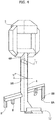
- the arms 6 each have two surfaces 6a, 6b opposite to one another, which are inclined with respect to a plane orthogonal to the main axis I of the tool, in particular by an angle ⁇ other than 0° and 90° ( Figure 4 ); the surface 6a faces the end portion 2, whereas the surface 6b faces the opposite end of the tool.
- the inclination of these surfaces is substantially the same for the various arms; in particular, the direction of inclination is kept constant given the same direction of rotation about the axis I.
- This configuration means that the surfaces 6a and 6b of the arms exert all together an action of thrust on the dough, in the direction W1 oriented towards the end portion 2 for the surfaces 6a, and in the direction W2 oriented towards the opposite end for the surfaces 6b, according to the direction of rotation of the tool about the axis X.
- a rotation in a clockwise direction causes an action of thrust by the surfaces 6b
- a rotation in a conterclockwise direction causes an action of thrust by the surfaces 6a.
- the arms 6 have a series of blades 8, which project towards one or the other of the two ends of the tool and are distributed along the extension of the corresponding arm.
- the blades 8 can be arranged in a direction parallel to the main axis I or else be inclined with respect thereto.
- the blades 8 of a single arm 8 may be variously oriented about the longitudinal axis of the arm.
- the blades 8 of a single arm project all on one and the same side.
- the blades 8 project towards the end of the tool opposite to the portion 2; i.e., they project downwards, in the case of a vertical-axis or oblique-axis tool.
- the blades 8 are substantially rectilinear and extend in a direction parallel to the shaft 4.
- the blades 8 have, in cross section, an elongated profile that is oriented along a corresponding circular path about the axis I so that they turn, in the two directions of rotation, opposite edges 8a, 8b, defined by the profile, that are able to penetrate easily into the dough ( Figure 5 ).
- the blades 8 of each arm have different lengths and are preferably arranged in order of increasing length from the inner end of the arm towards the outer end.
- a blade 8 is provided at its outer end, which hence constitutes the longest blade of the arm.
- the arms 6 carry thereon a single blade 8, preferably set at the outer end of the arm.
- further embodiments may envisage a plurality of blades 8 for each arm, all of one and the same length; also in this case it is preferable for a blade 8 to be set at the outer end of the arm.
- the tool 10 is equipped with a scraper member 12, mounted on the end of the tool opposite to the portion 2, which has the function of removing and lifting the material that deposits on the bottom of the bowl of the kneading machine, via an action of scraping induced by the movement of rotation of the tool.
- the member 12 is in particular constituted by a plate 12a, set in a plane orthogonal to the axis I and projecting radially with respect to the shaft 4, and by a layer 12b of anti-friction material anchored on the face of the plate 12a that faces the side opposite to the portion 2 of the tool.
- the end portion 2 consists of a bracket structure that defines a central attachment flange 2a, on one end side thereof, and a cross member 2b on the opposite side, in a position set at a distance therefrom, to which the shaft 4is connected, in a central position.
- This bracket structure makes it possible to separate the flange 2a from the shaft 4, by providing between them the opening 18, which constitutes free and direct access to the flange 2a, designed to facilitate connection of the tool to the drive shaft of the kneading machine.
- the arms 6 have the function of pushing the dough selectively upwards or downwards according to the direction of rotation of the tool so as to bring about mixing of the dough in a vertical plane.
- the kneading machine may be set so as to alternate the two directions of rotation of the kneading tool, thus amplifying the action of mixing performed by the tool.
- the blades 8 penetrate into the dough so as to divide it in a number of planes, this bringing about a mixing of the dough that occurs prevalently in a horizontal plane.
- the action exerted by the arms 6 and by the blades 8 hence causes movement of the dough in a number of directions, subjecting it to an extremely intense mixing operation.
- the operation of the tool described herein provides a mode of operation thereof such that the dough is pushed from top down, and laterally, from right to left, or vice versa.
- the solution described herein regards also a method for carrying out a kneading operation in a kneading machine provided with a tool as described herein, which is mounted on said machine with its own main axis I aligned to an axis of rotation X of said machine, the method including the steps of:
- the method includes:
- the present applicant has found that the tool described herein makes it possible to obtain results that are considerably superior to those of conventional tools, and this above all when it is used for kneading high-fat doughs or loosely bound doughs, for example doughs for short pastry, cookies, and biscuits in general.
- the scraper member 12 prevents, during the kneading operation, accumulation on the bottom of the bowl of ingredients that remain unmixed, or else sticking thereon of a layer of dough.
- Preferred applications of the tool envisage its use both on kneading machines with rotating bowl and on kneading machines of a planetary type with fixed bowl (see Figure 7 ).
Landscapes
- Chemical & Material Sciences (AREA)
- Chemical Kinetics & Catalysis (AREA)
- Life Sciences & Earth Sciences (AREA)
- Engineering & Computer Science (AREA)
- Food Science & Technology (AREA)
- Manufacturing And Processing Devices For Dough (AREA)
- Food-Manufacturing Devices (AREA)
- Confectionery (AREA)
- Formation And Processing Of Food Products (AREA)
Applications Claiming Priority (1)
| Application Number | Priority Date | Filing Date | Title |
|---|---|---|---|
| IT102020000013876A IT202000013876A1 (it) | 2020-06-10 | 2020-06-10 | Attrezzo impastatore |
Publications (1)
| Publication Number | Publication Date |
|---|---|
| EP3922101A1 true EP3922101A1 (fr) | 2021-12-15 |
Family
ID=72356278
Family Applications (1)
| Application Number | Title | Priority Date | Filing Date |
|---|---|---|---|
| EP21176975.7A Pending EP3922101A1 (fr) | 2020-06-10 | 2021-05-31 | Machine de malaxage |
Country Status (3)
| Country | Link |
|---|---|
| US (1) | US12150452B2 (fr) |
| EP (1) | EP3922101A1 (fr) |
| IT (1) | IT202000013876A1 (fr) |
Families Citing this family (1)
| Publication number | Priority date | Publication date | Assignee | Title |
|---|---|---|---|---|
| CN115191470B (zh) * | 2022-07-18 | 2023-04-18 | 河北翱羊生物科技有限公司 | 一种羊肠衣浸洗加工设备 |
Citations (2)
| Publication number | Priority date | Publication date | Assignee | Title |
|---|---|---|---|---|
| US1995465A (en) * | 1933-11-04 | 1935-03-26 | Freyn Engineering Co | Stirring tank |
| EP3473107A1 (fr) * | 2017-10-17 | 2019-04-24 | Stephan Machinery GMBH | Dispositif et procédé de traitement et de transformation du chocolat ainsi qu'utilisation d'une machine universelle lors dudit procédé |
Family Cites Families (4)
| Publication number | Priority date | Publication date | Assignee | Title |
|---|---|---|---|---|
| US133625A (en) * | 1872-12-03 | Improvement | ||
| US30764A (en) * | 1860-11-27 | Machine foe | ||
| US1066665A (en) * | 1912-08-05 | 1913-07-08 | Charley B Seward | Churn. |
| US2000370A (en) * | 1933-03-02 | 1935-05-07 | Oakes & Burger Co | Milk pasteurizer |
-
2020
- 2020-06-10 IT IT102020000013876A patent/IT202000013876A1/it unknown
-
2021
- 2021-05-31 EP EP21176975.7A patent/EP3922101A1/fr active Pending
- 2021-06-09 US US17/342,793 patent/US12150452B2/en active Active
Patent Citations (2)
| Publication number | Priority date | Publication date | Assignee | Title |
|---|---|---|---|---|
| US1995465A (en) * | 1933-11-04 | 1935-03-26 | Freyn Engineering Co | Stirring tank |
| EP3473107A1 (fr) * | 2017-10-17 | 2019-04-24 | Stephan Machinery GMBH | Dispositif et procédé de traitement et de transformation du chocolat ainsi qu'utilisation d'une machine universelle lors dudit procédé |
Also Published As
| Publication number | Publication date |
|---|---|
| IT202000013876A1 (it) | 2021-12-10 |
| US12150452B2 (en) | 2024-11-26 |
| US20210386075A1 (en) | 2021-12-16 |
Similar Documents
| Publication | Publication Date | Title |
|---|---|---|
| EP0596884B1 (fr) | Outil de coupe ameliore | |
| EP1121193B1 (fr) | Malaxeur a melange force s'utilisant notamment comme betonneuse | |
| EP3922101A1 (fr) | Machine de malaxage | |
| CN115318146B (zh) | 一种耐用型保温材料的加工设备 | |
| EP3187050B1 (fr) | Pétrisseuse à utiliser dans le traitement des pâtes alimentaires | |
| DE602004002849T2 (de) | Bodenbehandlungs- und Reinigungssystem | |
| DE10101776B4 (de) | Einrichtung und Verfahren zum Formen eines kugelförmigen Gegenstandes | |
| EP1639928A1 (fr) | Ensemble de lames pour un robot ménager a commande électromotrice et robot ménager correspondant | |
| EP2681016B1 (fr) | Robot parallèle et procédé de commande | |
| CZ208495A3 (en) | Process and apparatus for material treatment | |
| EP3066188B1 (fr) | Moyen d'agitation pour fermenteur d'une installation de biogaz et procédé de fabrication d'un moyen d'agitation | |
| EP3342480B1 (fr) | Mélangeur avec outil de mélange | |
| EP3670400B1 (fr) | Installation de mise en uvre et procédé de mise en uvre | |
| KR20120101151A (ko) | 홈 가공 장치, 홈 가공 방법 및 판재 가공 장치 | |
| DE69916191T2 (de) | Fahrbares Gerät zum Mischen von Futter | |
| EP0631475B1 (fr) | Dispositif pour petrir de la pate | |
| EP0239829A2 (fr) | Outil mélangeur-pétrisseur | |
| EP0123033B1 (fr) | Dispositif de maintien pour pièces de fonderie dans des ateliers d'ébarbage | |
| DE2251457C3 (de) | Verfahren und Vorrichtung zum Homogenisieren von partikelförmigem Material | |
| DE2736641A1 (de) | Hack-, schlag- und mischvorrichtung fuer lebensmittel | |
| JPH0520426Y2 (fr) | ||
| AT527528A1 (de) | Austragvorrichtung für Schüttgut | |
| JP7045667B2 (ja) | 肥料散布機 | |
| CN213854026U (zh) | 一种奶酪搅拌罐 | |
| JP2003239274A (ja) | 地盤改良用撹拌機 |
Legal Events
| Date | Code | Title | Description |
|---|---|---|---|
| PUAI | Public reference made under article 153(3) epc to a published international application that has entered the european phase |
Free format text: ORIGINAL CODE: 0009012 |
|
| STAA | Information on the status of an ep patent application or granted ep patent |
Free format text: STATUS: THE APPLICATION HAS BEEN PUBLISHED |
|
| AK | Designated contracting states |
Kind code of ref document: A1 Designated state(s): AL AT BE BG CH CY CZ DE DK EE ES FI FR GB GR HR HU IE IS IT LI LT LU LV MC MK MT NL NO PL PT RO RS SE SI SK SM TR |
|
| B565 | Issuance of search results under rule 164(2) epc |
Effective date: 20211021 |
|
| STAA | Information on the status of an ep patent application or granted ep patent |
Free format text: STATUS: REQUEST FOR EXAMINATION WAS MADE |
|
| 17P | Request for examination filed |
Effective date: 20220518 |
|
| RBV | Designated contracting states (corrected) |
Designated state(s): AL AT BE BG CH CY CZ DE DK EE ES FI FR GB GR HR HU IE IS IT LI LT LU LV MC MK MT NL NO PL PT RO RS SE SI SK SM TR |
|
| STAA | Information on the status of an ep patent application or granted ep patent |
Free format text: STATUS: EXAMINATION IS IN PROGRESS |
|
| 17Q | First examination report despatched |
Effective date: 20231207 |