EP3922440B1 - Procédé de génération d'un ensemble de données de commande de rayonnement pour un dispositif de fabrication additive - Google Patents
Procédé de génération d'un ensemble de données de commande de rayonnement pour un dispositif de fabrication additive Download PDFInfo
- Publication number
- EP3922440B1 EP3922440B1 EP21178097.8A EP21178097A EP3922440B1 EP 3922440 B1 EP3922440 B1 EP 3922440B1 EP 21178097 A EP21178097 A EP 21178097A EP 3922440 B1 EP3922440 B1 EP 3922440B1
- Authority
- EP
- European Patent Office
- Prior art keywords
- irradiation
- work
- layer
- work packages
- packages
- Prior art date
- Legal status (The legal status is an assumption and is not a legal conclusion. Google has not performed a legal analysis and makes no representation as to the accuracy of the status listed.)
- Active
Links
Images



Classifications
-
- B—PERFORMING OPERATIONS; TRANSPORTING
- B29—WORKING OF PLASTICS; WORKING OF SUBSTANCES IN A PLASTIC STATE IN GENERAL
- B29C—SHAPING OR JOINING OF PLASTICS; SHAPING OF MATERIAL IN A PLASTIC STATE, NOT OTHERWISE PROVIDED FOR; AFTER-TREATMENT OF THE SHAPED PRODUCTS, e.g. REPAIRING
- B29C64/00—Additive manufacturing, i.e. manufacturing of three-dimensional [3D] objects by additive deposition, additive agglomeration or additive layering, e.g. by 3D printing, stereolithography or selective laser sintering
- B29C64/30—Auxiliary operations or equipment
- B29C64/386—Data acquisition or data processing for additive manufacturing
- B29C64/393—Data acquisition or data processing for additive manufacturing for controlling or regulating additive manufacturing processes
-
- B—PERFORMING OPERATIONS; TRANSPORTING
- B22—CASTING; POWDER METALLURGY
- B22F—WORKING METALLIC POWDER; MANUFACTURE OF ARTICLES FROM METALLIC POWDER; MAKING METALLIC POWDER; APPARATUS OR DEVICES SPECIALLY ADAPTED FOR METALLIC POWDER
- B22F10/00—Additive manufacturing of workpieces or articles from metallic powder
- B22F10/20—Direct sintering or melting
- B22F10/28—Powder bed fusion, e.g. selective laser melting [SLM] or electron beam melting [EBM]
-
- B—PERFORMING OPERATIONS; TRANSPORTING
- B22—CASTING; POWDER METALLURGY
- B22F—WORKING METALLIC POWDER; MANUFACTURE OF ARTICLES FROM METALLIC POWDER; MAKING METALLIC POWDER; APPARATUS OR DEVICES SPECIALLY ADAPTED FOR METALLIC POWDER
- B22F10/00—Additive manufacturing of workpieces or articles from metallic powder
- B22F10/30—Process control
- B22F10/36—Process control of energy beam parameters
- B22F10/366—Scanning parameters, e.g. hatch distance or scanning strategy
-
- B—PERFORMING OPERATIONS; TRANSPORTING
- B22—CASTING; POWDER METALLURGY
- B22F—WORKING METALLIC POWDER; MANUFACTURE OF ARTICLES FROM METALLIC POWDER; MAKING METALLIC POWDER; APPARATUS OR DEVICES SPECIALLY ADAPTED FOR METALLIC POWDER
- B22F10/00—Additive manufacturing of workpieces or articles from metallic powder
- B22F10/80—Data acquisition or data processing
-
- B—PERFORMING OPERATIONS; TRANSPORTING
- B22—CASTING; POWDER METALLURGY
- B22F—WORKING METALLIC POWDER; MANUFACTURE OF ARTICLES FROM METALLIC POWDER; MAKING METALLIC POWDER; APPARATUS OR DEVICES SPECIALLY ADAPTED FOR METALLIC POWDER
- B22F12/00—Apparatus or devices specially adapted for additive manufacturing; Auxiliary means for additive manufacturing; Combinations of additive manufacturing apparatus or devices with other processing apparatus or devices
- B22F12/40—Radiation means
- B22F12/44—Radiation means characterised by the configuration of the radiation means
- B22F12/45—Two or more
-
- B—PERFORMING OPERATIONS; TRANSPORTING
- B29—WORKING OF PLASTICS; WORKING OF SUBSTANCES IN A PLASTIC STATE IN GENERAL
- B29C—SHAPING OR JOINING OF PLASTICS; SHAPING OF MATERIAL IN A PLASTIC STATE, NOT OTHERWISE PROVIDED FOR; AFTER-TREATMENT OF THE SHAPED PRODUCTS, e.g. REPAIRING
- B29C64/00—Additive manufacturing, i.e. manufacturing of three-dimensional [3D] objects by additive deposition, additive agglomeration or additive layering, e.g. by 3D printing, stereolithography or selective laser sintering
- B29C64/20—Apparatus for additive manufacturing; Details thereof or accessories therefor
- B29C64/264—Arrangements for irradiation
- B29C64/277—Arrangements for irradiation using multiple radiation means, e.g. micromirrors or multiple light-emitting diodes [LED]
-
- B—PERFORMING OPERATIONS; TRANSPORTING
- B29—WORKING OF PLASTICS; WORKING OF SUBSTANCES IN A PLASTIC STATE IN GENERAL
- B29C—SHAPING OR JOINING OF PLASTICS; SHAPING OF MATERIAL IN A PLASTIC STATE, NOT OTHERWISE PROVIDED FOR; AFTER-TREATMENT OF THE SHAPED PRODUCTS, e.g. REPAIRING
- B29C64/00—Additive manufacturing, i.e. manufacturing of three-dimensional [3D] objects by additive deposition, additive agglomeration or additive layering, e.g. by 3D printing, stereolithography or selective laser sintering
- B29C64/20—Apparatus for additive manufacturing; Details thereof or accessories therefor
- B29C64/264—Arrangements for irradiation
- B29C64/277—Arrangements for irradiation using multiple radiation means, e.g. micromirrors or multiple light-emitting diodes [LED]
- B29C64/282—Arrangements for irradiation using multiple radiation means, e.g. micromirrors or multiple light-emitting diodes [LED] of the same type, e.g. using different energy levels
-
- B—PERFORMING OPERATIONS; TRANSPORTING
- B33—ADDITIVE MANUFACTURING TECHNOLOGY
- B33Y—ADDITIVE MANUFACTURING, i.e. MANUFACTURING OF THREE-DIMENSIONAL [3D] OBJECTS BY ADDITIVE DEPOSITION, ADDITIVE AGGLOMERATION OR ADDITIVE LAYERING, e.g. BY 3D PRINTING, STEREOLITHOGRAPHY OR SELECTIVE LASER SINTERING
- B33Y30/00—Apparatus for additive manufacturing; Details thereof or accessories therefor
-
- B—PERFORMING OPERATIONS; TRANSPORTING
- B33—ADDITIVE MANUFACTURING TECHNOLOGY
- B33Y—ADDITIVE MANUFACTURING, i.e. MANUFACTURING OF THREE-DIMENSIONAL [3D] OBJECTS BY ADDITIVE DEPOSITION, ADDITIVE AGGLOMERATION OR ADDITIVE LAYERING, e.g. BY 3D PRINTING, STEREOLITHOGRAPHY OR SELECTIVE LASER SINTERING
- B33Y50/00—Data acquisition or data processing for additive manufacturing
-
- B—PERFORMING OPERATIONS; TRANSPORTING
- B33—ADDITIVE MANUFACTURING TECHNOLOGY
- B33Y—ADDITIVE MANUFACTURING, i.e. MANUFACTURING OF THREE-DIMENSIONAL [3D] OBJECTS BY ADDITIVE DEPOSITION, ADDITIVE AGGLOMERATION OR ADDITIVE LAYERING, e.g. BY 3D PRINTING, STEREOLITHOGRAPHY OR SELECTIVE LASER SINTERING
- B33Y50/00—Data acquisition or data processing for additive manufacturing
- B33Y50/02—Data acquisition or data processing for additive manufacturing for controlling or regulating additive manufacturing processes
-
- G—PHYSICS
- G05—CONTROLLING; REGULATING
- G05B—CONTROL OR REGULATING SYSTEMS IN GENERAL; FUNCTIONAL ELEMENTS OF SUCH SYSTEMS; MONITORING OR TESTING ARRANGEMENTS FOR SUCH SYSTEMS OR ELEMENTS
- G05B19/00—Program-control systems
- G05B19/02—Program-control systems electric
- G05B19/18—Numerical control [NC], i.e. automatically operating machines, in particular machine tools, e.g. in a manufacturing environment, so as to execute positioning, movement or co-ordinated operations by means of program data in numerical form
- G05B19/408—Numerical control [NC], i.e. automatically operating machines, in particular machine tools, e.g. in a manufacturing environment, so as to execute positioning, movement or co-ordinated operations by means of program data in numerical form characterised by data handling or data format, e.g. reading, buffering or conversion of data
-
- G—PHYSICS
- G05—CONTROLLING; REGULATING
- G05B—CONTROL OR REGULATING SYSTEMS IN GENERAL; FUNCTIONAL ELEMENTS OF SUCH SYSTEMS; MONITORING OR TESTING ARRANGEMENTS FOR SUCH SYSTEMS OR ELEMENTS
- G05B19/00—Program-control systems
- G05B19/02—Program-control systems electric
- G05B19/18—Numerical control [NC], i.e. automatically operating machines, in particular machine tools, e.g. in a manufacturing environment, so as to execute positioning, movement or co-ordinated operations by means of program data in numerical form
- G05B19/4097—Numerical control [NC], i.e. automatically operating machines, in particular machine tools, e.g. in a manufacturing environment, so as to execute positioning, movement or co-ordinated operations by means of program data in numerical form characterised by using design data to control NC machines, e.g. CAD/CAM
- G05B19/4099—Surface or curve machining, making three-dimensional [3D] objects, e.g. desktop manufacturing
-
- G—PHYSICS
- G06—COMPUTING OR CALCULATING; COUNTING
- G06F—ELECTRIC DIGITAL DATA PROCESSING
- G06F30/00—Computer-aided design [CAD]
- G06F30/10—Geometric CAD
-
- B—PERFORMING OPERATIONS; TRANSPORTING
- B22—CASTING; POWDER METALLURGY
- B22F—WORKING METALLIC POWDER; MANUFACTURE OF ARTICLES FROM METALLIC POWDER; MAKING METALLIC POWDER; APPARATUS OR DEVICES SPECIALLY ADAPTED FOR METALLIC POWDER
- B22F12/00—Apparatus or devices specially adapted for additive manufacturing; Auxiliary means for additive manufacturing; Combinations of additive manufacturing apparatus or devices with other processing apparatus or devices
- B22F12/90—Means for process control, e.g. cameras or sensors
-
- B—PERFORMING OPERATIONS; TRANSPORTING
- B29—WORKING OF PLASTICS; WORKING OF SUBSTANCES IN A PLASTIC STATE IN GENERAL
- B29C—SHAPING OR JOINING OF PLASTICS; SHAPING OF MATERIAL IN A PLASTIC STATE, NOT OTHERWISE PROVIDED FOR; AFTER-TREATMENT OF THE SHAPED PRODUCTS, e.g. REPAIRING
- B29C64/00—Additive manufacturing, i.e. manufacturing of three-dimensional [3D] objects by additive deposition, additive agglomeration or additive layering, e.g. by 3D printing, stereolithography or selective laser sintering
- B29C64/10—Processes of additive manufacturing
- B29C64/141—Processes of additive manufacturing using only solid materials
- B29C64/153—Processes of additive manufacturing using only solid materials using layers of powder being selectively joined, e.g. by selective laser sintering or melting
-
- B—PERFORMING OPERATIONS; TRANSPORTING
- B29—WORKING OF PLASTICS; WORKING OF SUBSTANCES IN A PLASTIC STATE IN GENERAL
- B29C—SHAPING OR JOINING OF PLASTICS; SHAPING OF MATERIAL IN A PLASTIC STATE, NOT OTHERWISE PROVIDED FOR; AFTER-TREATMENT OF THE SHAPED PRODUCTS, e.g. REPAIRING
- B29C64/00—Additive manufacturing, i.e. manufacturing of three-dimensional [3D] objects by additive deposition, additive agglomeration or additive layering, e.g. by 3D printing, stereolithography or selective laser sintering
- B29C64/10—Processes of additive manufacturing
- B29C64/171—Processes of additive manufacturing specially adapted for manufacturing multiple 3D objects
- B29C64/182—Processes of additive manufacturing specially adapted for manufacturing multiple 3D objects in parallel batches
-
- B—PERFORMING OPERATIONS; TRANSPORTING
- B33—ADDITIVE MANUFACTURING TECHNOLOGY
- B33Y—ADDITIVE MANUFACTURING, i.e. MANUFACTURING OF THREE-DIMENSIONAL [3D] OBJECTS BY ADDITIVE DEPOSITION, ADDITIVE AGGLOMERATION OR ADDITIVE LAYERING, e.g. BY 3D PRINTING, STEREOLITHOGRAPHY OR SELECTIVE LASER SINTERING
- B33Y10/00—Processes of additive manufacturing
-
- G—PHYSICS
- G06—COMPUTING OR CALCULATING; COUNTING
- G06F—ELECTRIC DIGITAL DATA PROCESSING
- G06F2113/00—Details relating to the application field
- G06F2113/10—Additive manufacturing, e.g. three-dimensional [3D] printing
-
- Y—GENERAL TAGGING OF NEW TECHNOLOGICAL DEVELOPMENTS; GENERAL TAGGING OF CROSS-SECTIONAL TECHNOLOGIES SPANNING OVER SEVERAL SECTIONS OF THE IPC; TECHNICAL SUBJECTS COVERED BY FORMER USPC CROSS-REFERENCE ART COLLECTIONS [XRACs] AND DIGESTS
- Y02—TECHNOLOGIES OR APPLICATIONS FOR MITIGATION OR ADAPTATION AGAINST CLIMATE CHANGE
- Y02P—CLIMATE CHANGE MITIGATION TECHNOLOGIES IN THE PRODUCTION OR PROCESSING OF GOODS
- Y02P10/00—Technologies related to metal processing
- Y02P10/25—Process efficiency
Definitions
- the invention relates to a method for generating an irradiation control data set for the additive manufacturing of a number of manufactured products or components in a manufacturing process.
- the invention comprises a method for generating an irradiation control data set for creating control data for a device for the additive manufacturing of at least a number of components in a manufacturing process, in which at least one layer of a build-up material is introduced into a process space and the build-up material of the layer is selectively solidified into component layers by irradiating at least a partial area of the layer using a plurality of irradiation resources, e.g. lasers.
- a plurality of irradiation resources e.g. lasers.
- the invention further relates to a corresponding irradiation control data set, a method for additive manufacturing, a corresponding control data generation device, a device for the additive manufacturing of a number of manufactured products and corresponding control data.
- a device for additive manufacturing is also referred to below as a manufacturing device or machine for short.
- additive manufacturing processes are those manufacturing processes in which a manufactured product or component is built up by depositing material, usually on the basis of digital 3D design data.
- the construction is usually, but not necessarily, layer by layer.
- 3D printing is often used as a synonym for additive manufacturing; the production of models, samples and prototypes using additive manufacturing processes is often referred to as “rapid prototyping” and the production of tools as “rapid tooling”.
- rapid prototyping the production of tools as “rapid tooling”.
- a key point is the selective solidification of the construction material, whereby this solidification can be carried out in many manufacturing processes with the help of irradiation with radiation energy, e.g.
- electromagnetic radiation in particular light and/or heat radiation, but possibly also with particle radiation, such as electron beams.
- particle radiation such as electron beams.
- processes that use irradiation are "selective laser sintering" or “selective laser melting”.
- thin layers of a mostly powdery building material are repeatedly applied on top of each other and in each layer the building material is selectively solidified by spatially limited irradiation of the areas that are to belong to the manufactured product after production, by the powder grains of the The building material can be partially or completely melted using the energy introduced locally by the radiation at this point. After cooling, these powder grains are then bonded together to form a solid body.
- the document DE 10 2017 205051 A1 discloses a computer-aided method for generating a control data set for a generative layer building device for producing a three-dimensional object by means of the same; during production, a plurality of beams are directed at different regions of an applied layer of building material for the object.
- each of the irradiation resources is permanently assigned to a specific area in the process space, i.e. the surface of the layer to be processed is divided into fixed areas and each of the irradiation resources is permanently assigned to one of these areas over the entire height of the component to be manufactured, i.e. in the direction of construction in the process space across all layers. Only in a border area can more than one of the irradiation resources be used. For example, with a four-scanner machine, the layer is divided into four quadrants and there is a cross-shaped overlap area, whereby all four irradiation resources or scanners can only work in the middle.
- Such machines with multiple irradiation resources are generally faster than machines with just one irradiation resource, but the fixed allocation of irradiation resources to specific layer areas has the disadvantage that the various irradiation resources are unevenly utilized depending on the component to be manufactured or components to be manufactured in parallel, and therefore the speed of building up a layer always depends on how long the irradiation resource that is most in demand in the current layer takes. If all irradiation resources are constructed and arranged in such a way that they could in principle reach every area of a layer within the process space, there would in principle be greater flexibility.
- an irradiation strategy is defined before the start of the production process, in which the irradiation resources are assigned to predetermined layer areas in advance, for example again a division into quadrants, purely according to components or similar.
- some or all components can be irradiated by several irradiation units.
- the irradiation of a layer with selective hardening of component cross-sections should generally be carried out in as
- the method according to the invention serves to generate an irradiation control data set.
- This irradiation control data set in turn serves to create control data for a device for the additive manufacture of a number of components (at least one component, but also several components) in a manufacturing process.
- at least one layer of a building material is introduced into a process space and solidified by irradiating at least a portion of the layer to form at least one component layer.
- the building material can be pasty or powdery, e.g. a metal-based or polymer-based powder. Solidification takes place selectively using a plurality of irradiation resources, with several, preferably at least two, more preferably at least three, particularly preferably at least four, irradiation resources being controlled or used.
- At least one component is therefore manufactured from at least one component layer, but usually from a large number of component layers.
- Several components can also be manufactured in which their respective component layers are solidified in the respective layer of the construction material by the irradiation resources at the corresponding locations.
- Each component layer can be divided into layer segments. This division into layer segments can be applied to different structures of a component layer. based (e.g. contour, DownSkin, UpSkin, InFill) or a subdivision of work steps for creating the component layer (if a jump occurs, i.e. the respective irradiation resource is switched off and at the same time a target location of the irradiation is moved, a subdivision occurs).
- the layer segments therefore correspond to geometric arrangements of layered solidifications of a building material or of layered geometric shapes.
- Each layer segment can be assigned (at least) one "work package".
- Such a work package is a process-technical representation of a layer segment and represents, for example, a set of work steps for creating the corresponding layer segment or an abstract object of this layer segment in a workflow.
- a work package can be assigned to a contour of a component, for example. This contour is a layer segment of the outer border of a component, in particular a closed component cross-section. Other work packages can be assigned to the InFill of the component layer. The term InFill refers to a filling of the component cross-section bordered by the contour. Still other work packages can be assigned to the layer segments UpSkin or DownSkin, which are each a filling within the contour, but can also be part of the contour under certain circumstances. DownSkin refers to an area of a component that is to be solidified or solidified and that borders on non-solidified or loose building material that is arranged below the solidified or solidified building material during the construction process.
- UpSkin refers to an area of a component that is to be solidified or solidified and that borders on non-solidified or loose building material that is arranged above the solidified building material during the construction process.
- contour, InFill, DownSkin and UpSkin can alternatively or additionally each include a defined method of selective solidification of the area designated in this way, e.g. a characteristic set of irradiation parameter values.
- a work package can, for example, correspond to the technical representation of a contour (the data object "contour, component X, layer Y, position") or the sequence of concrete work steps for creating this contour.
- an irradiation resource can, for example, solidify a complete contour of a component cross-section in a layer, either directly with the work steps provided by the work package or by means of work steps derived from the corresponding work package.
- An irradiation resource is understood to be a separately controllable beam or radiation emission location.
- a radiation emission location can also be understood to be, for example, a controllable mirror system (the so-called scanner), i.e., for example, that a radiation source supplies several such mirror systems.
- each irradiation resource can also have its own radiation source with an associated scanner.
- the use of separate radiation sources for the individual irradiation resources for example, the construction of each irradiation resource with its own scanner and its own laser, has the advantage that no beam splitters or the like have to be used and, for example, if a radiation source fails, not several irradiation resources are affected. Nevertheless, in some cases, using a single radiation source for several irradiation resources can be advantageous for cost and/or space reasons.
- Preferred irradiation sources here are light-emitting irradiation sources such as lasers.
- a preferred irradiation resource includes a beam source, e.g. a laser or an electron beam source, which is able to generate a beam that can solidify the building material, a scanner and often also an optical device for focusing the beams.
- a scanner is an optical device with which a beam can be deflected.
- a scanner can include several deflection devices in order to be able to deflect the beam in several axes. If the beam source has sufficient power and the beams are focused on a specific "point" (i.e. a specific location) of a layer, the building material is melted. By changing the deflection of the scanner, the point can be moved in the plane of the layer. A track of melted or sintered building material can be created along the trajectory of this point. This track is also referred to as a "melting track”. The speed at which the point moves in the plane of the layer is also referred to as the "scanning speed".
- the component layers or layer segments are irradiated in the form of an irradiation pattern by the irradiation resource.
- An irradiation pattern is a geometric arrangement of melt paths with which a geometric shape is traced or filled. This can, for example, be a filling of an area with a line pattern (e.g. for an up-skin or down-skin area), or a path along the component surface (e.g. for a contour).
- This irradiation pattern can be realized in the form of irradiation parameters.
- the term "irradiation parameters" is understood to be an abstract description of an irradiation pattern linked to parameters for generating control commands. These can be constant power specifications and scanning speeds, as well as generation instructions specified as functions.
- irradiation parameter therefore also includes concrete irradiation parameter values within the scope of this application.
- An irradiation pattern can be a simple method of deflecting the scanner along a trajectory in a feed direction, but can also contain a substructure (e.g. "hatching"). To solidify at least a partial area of the layer, the irradiation point is often moved according to the control data along a number of scan lines that are arranged within an irradiation strip, for example like a hatch, which is why these scan lines are also referred to as "hatch lines".
- advance direction refers to the direction in which the trajectory is/would be followed without a substructure. This means that the term refers to the direction in which the solidification spreads along the course of the actually solidified irradiation strip during the production of the component layer.
- the solidification preferably spreads in a direction along the longitudinal extent of the irradiation strip.
- the advance direction describes the spread or progression of the solidification on a macro level, i.e. on the level of the entire irradiation strip.
- advance direction does not refer in particular to a micro level of solidification, i.e. to the movement of the irradiation point along the individual scan lines within an irradiation strip. In other words, during hatching, a movement of the irradiation point along the scan lines on a micro level causes the solidification to spread along the irradiation strip on a macro level.
- a work package can include such irradiation parameters or contain data by means of which irradiation parameters can be generated.
- a work package contains an abstracted form of travel commands for a scanner and temporally or spatially assigned target powers for a radiation source.
- An irradiation parameter can be assigned to a work package.
- Control commands for irradiating a sequence of melt tracks can be generated for a work package for a specific irradiation resource.
- This layer data includes data from which control data for creating layer segments for a component layer can be determined, in particular irradiation parameters or data from which irradiation parameters can be determined.
- the layer data can include, for example, geometric data, e.g. information about a cross-section of a component whose outline is formed by coordinate points in the x/y plane, i.e. a virtual plane parallel to the real construction field of the production device. Each plane or layer has an individual z coordinate.
- the layer data can also include directional information for scanning by a beam used for solidification, power/speed of the beam and distance between trajectories and other data. b) Distribution of the shift data into several work packages to form a basic set of work packages.
- At least one work package is assigned to each layer segment, whereby each work package is assigned to a layer segment, but several work packages can be assigned to a layer segment.
- a layer segment can be a continuous contour, in which case it is preferable to assign a work package to this contour.
- a layer segment can also be an in-fill of a contour in which multiple deposits are made (for example, the beam is switched off and the scanner is moved), whereby in this case each part after a deposit is preferably a separate work package and all of these work packages are assigned to the layer segment.
- a work package can comprise a sequence of commands for controlling a laser and the scanner or alternatively an electron beam and a deflection field (i.e. an irradiation resource).
- a work package can therefore represent the command sequence for a component or even a sub-area of a component, e.g. areas with different irradiation patterns or different parameterization (scanning speed, power, possibly intensity distribution) can be viewed as separate work packages.
- a work package can also be a data object that represents the aforementioned sequence of commands.
- a division of a layer segment into several work packages is particularly advantageous if it should be further subdivided due to the geometrical extent and/or processing time, e.g. if irradiation in the form of a stripe pattern, a specified maximum stripe length is exceeded, or when specified working ranges of irradiation resources are exceeded.
- irradiation in the form of a stripe pattern a specified maximum stripe length is exceeded, or when specified working ranges of irradiation resources are exceeded.
- the division preferably takes place at points where the laser is switched off for a jump to the next line. In most cases, this means that no shortened scan vectors arise within a stripe.
- All work packages can initially be part of the basic set of all work packages and are preferably also initially part of the basic set, whereby this basic set can in particular comprise an order of these work packages, e.g. in the form of a directed graph.
- This basic set is reduced in the course of the method by work packages, which are then assigned to work package groups and removed from the basic set. This advantageously leads to shift data being able to be distributed in the form of work packages across several irradiation resources. c) Provision of a clearly defined sequence relation for the work packages.
- This sequence relation includes the sequence to be followed for different layer segments of a component (e.g. contours first, then DownSkin or UpSkin and finally InFill) and in particular represents general rules for ordering work packages.
- adhering to a certain sequence can be advantageous depending on the material.
- an improvement in the surface quality of a component can be achieved if areas on the surface are irradiated or solidified first.
- This predetermined sequence results in dependencies between the work packages depending on their affiliation to the different areas.
- a preferred sequence relation can include a directed graph that includes the work sequence of layer segments or rules about which type of layer segments or work packages must be completed before other layer segments or work packages (e.g. "contour first, then InFill").
- Determination of a processing sequence of the work packages based at least on the sequence relation.
- the step preferably results in a simply directed graph of the work packages (i.e. a graph without loops).
- This graph can be seen as a new basic set, but it can also be seen as a representation of the basic set for further steps.
- the directed graph is created in addition to the basic set. This has the particular advantage that work packages can then be taken into account that have not yet been processed at a time relevant to the process, but have already been assigned. The assigned work packages can then be deleted from the basic set, but still be present in the graph (and "block" the subsequent work packages). Only work packages that are contained in both the graph and the basic set can then be considered (i.e.
- One advantage of the feature is an improvement in component properties, e.g. with regard to the surface structure. e) Determination of an (expected) completion time for each of the irradiation resources for each work package group of the work packages that have already been previously assigned to these irradiation resources.
- Each work package group includes the work packages for an irradiation resource that have already been assigned to it and, if applicable, waiting times, and can of course also contain no element if no work package has yet been assigned.
- the completion time is the amount of time that an irradiation resource needs to process the work packages and includes the time that each of the work packages included needs and, if applicable, additional waiting times. As a rule, the completion times for different irradiation resources are different, but they can also be the same, especially at the beginning when the completion time is 0.
- the time required to complete each work package or at least a group of work packages can be determined in advance. This is, for example, the time required for irradiation, possibly including jump times between trajectories of a work package to be consolidated during which no irradiation takes place.
- the time can be estimated in advance or determined by simulation depending on the assignment of the work packages to the irradiation resources. This step is preferred for determining the completion time, but not absolutely necessary, since this can also be determined again and again from the work package groups.
- Selection of an irradiation resource taking into account the completion time determined for it, preferably the irradiation resource with the shortest determined completion time (i.e. the earliest completion time).
- An irradiation resource is selected, preferably the one that is completed first based on the current status of the work package distribution. If several irradiation resources with the same shortest completion time are possible, then one of the irradiation resources can be selected based on other parameters, e.g. randomly, based on the position or the last component processed.
- a check can be made to see whether all of the work packages ordered in step d) can already be processed in a production process. For example, it may be the case that a group of work packages cannot be carried out at the time in question because a work package that must be carried out beforehand is still being processed by another irradiation resource and has not yet been completed. The work packages in question can then be removed from the processing sequence or their selection can be blocked.
- One advantage of the feature is the reduction in construction time by improving the utilization of the irradiation resources. g) Determination of a selection set of work packages from the basic set of work packages, based on the sequence relation, whereby the selection set comprises those work packages which can be processed according to the processing sequence.
- a filter is also carried out to determine whether all necessary work packages could already be processed in a real process (see above) or whether user specifications exist that prohibit or require processing of a work package. Further filtering can also be carried out in this step, e.g. whether work packages can be processed by the selected irradiation resource at all.
- the selection set therefore contains those work packages that can be processed in the shortest processing time determined, at least based on the sequence relationship.
- One advantage of the feature is the improvement in the utilization of the irradiation resources while adhering to the sequence relationship, which in turn leads to an improvement in component properties. h) Selection of a work package from the selection set taking into account a given evaluation rule.
- a single work package can be selected, but also a group of work packages, although the selection of a single work package is preferred.
- the selection is made on the basis of the evaluation rules.
- This evaluation rules is used to evaluate work packages with a view to a selection.
- a work package is therefore selected from the work set, which is the most suitable. It is preferred that an individual evaluation value is assigned to the work packages in the selection set on the basis of the evaluation rules. This evaluation value can, for example, be based on the extent to which the selected irradiation resource is suitable for carrying out the work package in question.
- the evaluation rules could specify: "Just take the next work package in the selection set". By selecting from the selection set, it is ensured that the work package can be carried out at the current point in time (at the time of the shortest completion time).
- the different work packages in the selection set are compared with each other to select the work package that is most suitable for assignment (based on the rating).
- the prerequisite for this is the definition of a comparison operator that allows a statement to be made as to whether assigning one work package makes more sense than assigning another.
- This comparison operator is derived from the rating rules. In the simplest case, the comparison can involve two numerical ratings, but it is also possible to carry out this comparison, for example, using a list of priorities or a classification. If a numerical rating takes place, the selected work packages can be assigned a value based on their rating. If the quality of an rating is linked to a high value, the work package with the highest value is preferred. If the quality of an rating is linked to a low value, the work package with the lowest value is preferred.
- criteria that have an impact on certain component properties are given higher priority and can be given a higher weighting.
- Prioritization within this group is preferably done specifically for different materials and processes, so that the criterion that has the greatest influence on a certain component property is given the highest rating, i.e. with a correspondingly high weighting factor. is weighted and/or is checked first in the nested comparison. For example, some build materials react particularly sensitively to the beam angle of a laser, while for other build materials the direction of movement of the laser spot on the build material has a greater influence on certain component properties.
- the number of subsequent work packages that require the work package in question can be compared first; if these numbers are the same, the position opposite to the flow direction is compared.
- the order of the comparisons defines a prioritization of important to less important criteria. This means that as part of the evaluation, a first group of (particularly important) evaluation criteria from the evaluation rules is preferably used first and, if two or more work packages are rated equally with the highest rating, these work packages are evaluated with another group of (particularly next most important) evaluation criteria from the evaluation rules until only one best-rated work package or no evaluation criteria remain.
- B(B 0 ,..B N ) sum(W i * B i ), where W i are weighting factors.
- Both methods can also be combined by using the numerical evaluation in a nested comparison.
- One advantage of the feature is that the construction time or the component quality can be improved.
- the preferred implementation does not require computationally intensive iterative optimization. i) Assigning the selected work package to a work package group which is assigned to the currently selected irradiation resource and removing this work package from the basic set of work packages.
- the selected work package is therefore assigned to an irradiation resource. Since the entire process can be carried out in advance of a processing and is not necessarily linked to a specific machine (only the number and positioning of the irradiation resources relative to each other and relative to the construction area should be identical), it is It is only necessary to assign the selected work package to a work package group, which in turn is assigned to the selected irradiation resource. This gives you a data set of work package groups that contain work data for the respective irradiation resources of a device for the additive manufacturing of a number of components.
- the assigned work packages are deleted from the basic set. This means that when the process is repeated with the modified basic set, the work packages are usually processed in different sequences for each run. j) repeating at least steps d) to i) until a predetermined termination criterion is reached.
- a preferred termination criterion is the number of work packages assigned or remaining, with a preferred termination condition providing for a distribution of all work packages.
- Other specified or additional steps can also be included in the repetition, although it is preferable not to carry out steps more than once if the result does not change.
- An irradiation control data set according to the invention has been generated by means of a method according to the invention. It preferably contains work package groups with work packages for the individual irradiation resources.
- the irradiation control data set can already include concrete irradiation parameters or just abstract work packages from which irradiation parameters can be derived.
- Control data according to the invention for controlling a device for additive manufacturing are designed such that they were generated using an irradiation control data set according to the invention.
- the invention can be implemented in the form of a computer unit with suitable software.
- the control data generation device which can be implemented in the form of suitable software program parts in the computer unit.
- the computer unit can, for example, have one or more microprocessors or the like that work together.
- a largely software-based implementation has the advantage that control devices that have already been used can also be easily retrofitted by means of a software or firmware update in order to work in the manner according to the invention.
- a corresponding computer program product with a computer program that can be loaded directly into a storage device of a computing device (in a control data generation device and/or a control device of a device for additively manufacturing a component layer of a component), with program sections to carry out all steps of the method according to the invention when the program is executed in the computing device.
- a computer program product can optionally include additional components such as documentation and/or additional components, including hardware components such as hardware keys (dongles, etc.) for using the software.
- a computer-readable medium for example a memory stick, a hard disk or another portable or permanently installed data carrier, on which the program sections of the computer program that can be read and executed by a computer unit of the control device or monitoring device are stored, can be used for transport to the control device and/or for storage on or in the control device or monitoring device.
- One advantage of this development of the method according to the invention is an improvement in component properties; a distinction can be made between different irradiation resources which can, for example, have a different power spectrum, a different beam diameter, or a different intensity distribution.
- an evaluation value is calculated in each case, whereby the evaluation rule is designed in such a way that it assigns a numerical value to at least one criterion. It is particularly preferred that different criteria are additionally assigned different weightings, or that the evaluation rule weights criteria differently numerically.
- a work package whose execution at the relevant time (in the shortest completion time) lies outside an expected plume that is created when another work package is executed by a different radiation resource is assigned a better rating (e.g. a higher rating value) than work packages whose execution lies within this plume.
- An advantage of taking into account the spatial distance of the work package from the selected irradiation resource is that it can, for example, lead to a reduction in smoke development and an improvement in component properties.
- An advantage of considering the location of a work package relative to the extent/location of a smoke exhaust area is that irradiation of an area shadowed by smoke can be avoided, which can lead to an improvement of component properties (e.g. lower porosity and/or improved mechanical properties of the component).
- An advantage of taking into account the spatial distance of the work package to a previously assigned work package is that a reduction in construction time can be achieved by reducing jump distances of an irradiation resource between the areas of different work packages and thus a reduction in unproductive completion time
- an improvement in component properties can be achieved by continuing solidification after a still warm, previously solidified area.
- An advantage of taking into account the number of work packages that the work package in question requires is that this can lead to a reduction in completion time.
- the last point of the criteria is particularly important when using electron beams. These must not be too close to each other, as their electric fields can have a negative effect on each other. But even when using light beams, local temperature distributions can occur that can have a negative effect on each other.
- the selected work package can also be irradiated by another irradiation resource and whether this other irradiation resource is better suited to completing the work package with regard to a predetermined criterion, in particular with regard to an angle of incidence (on the construction site) or angle of deflection of a beam of the irradiation resource and/or distance to the work package.
- This can be easily decided based on the position at which the work package is to be carried out. If the other irradiation resource is better suited, the other irradiation resource is declared to be the selected irradiation resource and the selected work package is assigned to a work package group that is assigned to this (new) currently selected irradiation resource.
- the completion times of the relevant irradiation resources without the relevant work package are preferably also compared with each other.
- a change of the selected irradiation resource only takes place if the relevant completion times differ by a maximum of a predetermined period of time.
- a budget for the entire layer could also be used for the specified time period and the completion time could be simulated with and without changes. This could in turn be made dependent on a layer-specific minimum layer time that is necessary in order not to exceed a specified substrate temperature (e.g. the temperature of the surface of the build material). This minimum layer time can be calculated by thermal simulation or determined by measuring the temperature of the build area.
- the evaluation (in particular a determination of the evaluation values) is preferably carried out by means of an iterative optimization of a schedule, in particular by means of an optimization of the completion time.
- a preferred optimization algorithm calculates a set of evaluations and resulting decisions for each iteration and thus the assignment to the work package groups (the irradiation units) and the chronological sequence for the entire shift. The result is then evaluated using a cost function. For the first iteration, these decisions can basically be made arbitrarily, but preferably based on the evaluation rules. In order to generate further solutions and thus sets of decisions, different Algorithms are known, for example genetic algorithms, which combine the decisions from previous iterations. This is also referred to as combinatorial optimization.
- An advantage of this development of the method according to the invention is that an optimized schedule can be determined using the cost function, which can improve construction time and component properties, although this requires a certain amount of computing time.
- the processing sequence of the work packages is also determined according to a user specification.
- a user specification Preferably, only user specifications are taken into account (or only such user specifications are permitted) that satisfy the sequence relation.
- the user specification preferably includes a specification for a feed direction and/or a specification for an assignment of an irradiation resource to a (specific) component.
- the component in question is therefore completely or defined parts of the component are essentially manufactured by the irradiation resource in question.
- the work packages are arranged in a simply directed graph based on the sequence relation to determine the processing sequence.
- the work packages are present as nodes and their relationship (work flow) to one another is in the form of directed edges according to the sequence relation.
- the selection set of work packages from the basic set of work packages, only those work packages are preferably used for which no work package in the graph has to be processed beforehand. In relation to the graph, this means that no work package to which an edge leads is included in the selection set. This means that start nodes or no successors are always selected.
- the basic set of work packages is the directed graph or includes it. The graph always represents the state at the time of assignment.
- the selected irradiation resource is assigned a predetermined waiting time instead of a work package. No work package is then deleted from the basic set and at least the repeated steps of the method are carried out again.
- the waiting time is preferably predetermined in the sense of a time value or is calculated dynamically based on criteria (e.g. processing by the other irradiation resources). It is preferred that the length of the waiting time is such that at least one further work package is completed by another irradiation resource during this time.
- a preferred simple structure of a processing sequence in particular of a directed graph, can be based purely on membership in certain areas.
- the input is a list containing layer segments in the desired order, of which all layer segments are considered starting with the second entry in the list. For each work package that belongs to the previous layer segment (therefore starting with the second layer segment), a dependency is added to the processing sequence to all work packages that belong to the layer segment currently being considered.
- a preferred further structure of a processing sequence in particular a directed graph, in which the relationships are restricted to topologically connected areas, can be achieved as follows.
- the advantage of such a processing sequence is that the number of dependencies between the work packages is reduced, so that there are more options for dividing the work packages between the irradiation resources.
- individual layer segments are considered from a list in which layer segments are contained in the desired order and all layer segments are run through in a loop starting with the second entry in the list.
- work packages from the previous segment are determined that are adjacent to the first work package.
- a dependency to the first work package is added in the processing sequence.
- a list of adjacent predecessors of work packages is used.
- irradiation sequence may conflict with the already specified relative order between the work packages. For example, to avoid laser/smoke interactions, it may be required that the work packages are irradiated in the opposite direction to the flow direction.
- the following features could be part of the evaluation rules, but they could also be used to determine the processing sequence.
- Figure 9 shows a flow chart of an embodiment for creating another processing sequence, another directed graph GG.
- This flow chart describes an algorithm that adds dependencies for work packages in an area potentially shaded by smoke, if this does not result in a contradiction.
- the input is a basic set with all work packages and the processing sequence (eg the directed graph), which already contains all the necessary dependencies, eg due to the irradiation sequence of the layer segments.
- the processing sequence eg the directed graph
- the advantage of the invention is a particularly high productivity (short construction time) through a more even utilization of all irradiation resources, a fixed adherence to a predetermined relative irradiation sequence between the layer segments (contour, down skin, up skin, infill, etc.) and a resulting improved component quality (e.g. in relation to the mechanical properties of the component, such as its breaking or tensile strength, but also in relation to its surface quality), which is further improved in particular by the preferred minimization of changes in the irradiation resources, in particular on the component surface.
- the most suitable irradiation resource is assigned (e.g. the laser with the most favorable angle of incidence on the construction material), a preferred irradiation direction is maintained relative to the position of the scanner, a preferred irradiation direction is maintained relative to the laminar flow and smoke-laser interactions are avoided.
- laser sintering device 1
- exposure is used synonymously with the term “irradiation”.
- Such a laser sintering device 1 is shown schematically in Figure 1 shown.
- the device has a process chamber 3 or a process space 3 with a chamber wall 4, in which the manufacturing process essentially takes place.
- a container 5 that is open at the top and has a container wall 6.
- the upper opening of the container 5 forms the current working plane 7.
- the area of this working plane 7 that lies within the opening of the container 5 can be used to build the object 2 and is therefore referred to as the construction field 8.
- the container 5 has a base plate 11 that is movable in a vertical direction V and is arranged on a carrier 10. This base plate 11 closes off the container 5 at the bottom and thus forms its base.
- the base plate 11 can be formed integrally with the carrier, but it can also be a plate formed separately from the carrier 10 and attached to the carrier 10 or simply mounted on it.
- a construction platform 12 can be attached to the base plate 11 as a construction base on which the object 2 is built. In principle, however, the object can also be built on the base plate 11 itself, which then forms the construction base.
- the basic construction of the object 2 is carried out in such a way that a layer of building material 13 is first applied to the construction platform 12, then the building material is selectively solidified with a laser at the points which are to form parts of the object 2 to be manufactured, then the base plate 11, thus the construction platform, is lowered with the aid of the carrier 10 and a new layer of the building material 13 is applied and then selectively solidified, etc.
- the working level 7 located in the construction field 8 then corresponds to the current layer.
- Figure 1 the object 2 constructed in the container 5 on the construction platform 12 is shown in an intermediate state below the working level. It already has several solidified layers S, surrounded by unsolidified construction material 13.
- construction material preferably Powders, especially metal powder, plastic powder, ceramic powder, sand, filled or mixed powders or even pasty materials.
- Fresh build material 15 is located in a storage container 14 of the laser sintering device 1. With the aid of a coater 16 that can be moved in a horizontal direction H, the build material can be applied in the form of a thin layer in the working plane 7 or within the construction field 8.
- an additional radiant heater 17 is located in the process chamber 3. This can be used to heat the applied build-up material 13 so that the irradiation device used for selective solidification does not have to introduce too much energy. This means that, for example, with the help of the radiant heater 17, a quantity of basic energy can be introduced into the build-up material 13, which is of course still below the energy required for the build-up material 13 to melt or sinter.
- An infrared radiator can be used as the radiant heater 17, for example.
- the laser sintering device 1 has an irradiation device 20 or, more specifically, an exposure device 20, which comprises a plurality of irradiation resources 21a, 21b.
- each irradiation resource 21a, 21b has its own laser 22a, 22b as a radiation source 22a, 22b, which generates its own laser beam L.
- This laser beam L is deflected in each case via its own deflection device 23a, 23b (also called a scanner 23a, 23b).
- This deflection device 23a, 23b can be a controllable mirror system.
- each laser beam L is then focused in a suitable manner onto the working plane 7 by a focusing device 24a, 24b, which is also assigned to the irradiation resource 21a, 21b.
- the entire irradiation device 20 is located outside the process chamber 3, and the laser beams L are each guided into the process chamber 3 via a coupling window 25 attached to the top of the process chamber 3 in the chamber wall 4.
- the lasers 22a, 22b can be gas or solid-state lasers or any other type of laser such as laser diodes, in particular VCSEL (Vertical Cavity Surface Emitting Laser) or VECSEL (Vertical External Cavity Surface Emitting Laser).
- the lasers 22a, 22b can be constructed in the same way or differently. It is also not absolutely necessary that all irradiation resources 21a, 21b are constructed in the same way.
- the laser sintering device 1 further contains a sensor arrangement 40 which is suitable for detecting process radiation emitted during the impact of the laser beams L on the building material 13 in the working plane 7.
- This sensor arrangement 40 operates in a spatially resolved manner, i.e. it is able to detect a type of emission image of the respective layer S.
- an image sensor or a camera which is sufficiently sensitive in the area of the emitted radiation is used as the sensor arrangement 40.
- one or more sensors could also be used to detect optical and/or thermal process radiation, e.g. photodiodes which detect the electromagnetic radiation emitted by the impinging laser beams L, or temperature sensors for detecting emitted thermal radiation.
- the sensor arrangement 40 is arranged within the process chamber 3. However, it could also be located outside the process chamber 3 and then detect the process radiation, for example, through another window in the process chamber 3.
- the measurement signals MS recorded by the sensor arrangement 40 are transferred to a control device 30 of the laser sintering device 1, which also serves to control the various components of the laser sintering device 1 for the overall control of the additive manufacturing process.
- the control device 30 has a measurement signal interface 33, at which the measurement signals MS are taken from the process chamber 3.
- a measurement signal evaluation unit 34 can then be evaluated by a measurement signal evaluation unit 34 to determine whether there have been any disruptions within the manufacturing process, for example whether, when several components are manufactured at the same time, further completion of one of the components is no longer sensible, since, taking into account the measurement signals MS, it is to be expected that this component is scrap anyway.
- the control device 30 here has an online control strategy modification unit 31, which can control the components of the irradiation device 20, i.e. here the individual irradiation resources 21a, 21b and their individual components, namely the lasers 22a, 22b, the deflection device 23a, 23b and the focusing devices 24a, 24b, each separately using suitable irradiation control data BS.
- the control strategy modification unit 31 outputs the current irradiation control data BS to the components of the irradiation resources 21a, 21b in such a way that they follow a defined irradiation strategy ST, wherein this irradiation strategy ST is specified by the irradiation data set according to the invention.
- the irradiation control data BS is output here via a data interface 32, via which the individual irradiation resources 21a, 21b or their components can also transfer function feedback FR to the control device 30 or here the control strategy modification unit 31.
- the control device 30 can also control the radiant heater 17 using suitable heating control data HS, the coater 16 using coating control data SD and the movement of the carrier 10 using carrier control data TS.
- the control device 30 here also has an interface 35, via which the entire device 1, here e.g. via a bus 50 or another data connection, can be coupled to a terminal 60 with a display or the like. An operator can use this terminal 60 to control the control device 30 and thus the entire laser sintering device 1.
- the device 1 could also be controlled via a user interface (not shown) integrated into the control device 30.
- process control data PS which can include the irradiation control data BS according to an irradiation strategy ST, the heating control data HS, the coating control data SD or the carrier control data TS, can be transmitted to the control device 30.
- the irradiation strategy ST is predetermined by the irradiation control data set according to the invention.
- the process control data PS can in particular also be stored in a memory 37 of the control device 30 for further use.
- a possible structure of a radiation strategy ST is described below using Figure 2 explained.
- the terminal 60 comprises a control data generation device 100 according to the invention.
- a control data generation device 100 By means of this, an optimized irradiation control data set is created from computer-generated 3D objects which have previously been broken down into slices. created, from which appropriately optimized process control data PS can be created for the laser sintering device.
- This control data generation device 100 and a method for creating a corresponding irradiation control data set are described below using exemplary embodiments.
- the present invention is not limited to such a laser sintering device 1. It can be applied to any other method for the generative or additive production of a three-dimensional object by layer-by-layer application and selective solidification of a building material, wherein several energy beams from separately controllable irradiation resources are emitted to solidify the building material to be solidified. Accordingly, the irradiation resources can not only be constructed with lasers, as described here, but any irradiation resource could be used with which energy can be selectively applied to or into the building material as wave or particle radiation. For example, other light sources, electron beams, etc. could be used instead of the lasers.
- component 2 In order for the method to be applied, component 2 (or the components 2 manufactured at the same time) must first be divided into component layers and then into layer segments. These layer segments (geometric objects) are always assigned a single work package (representation of the layer segment or sequence of construction steps) or a plurality of work packages.
- Figure 2 shows the distribution of the cross-sectional area of a component 2 (component layer SB) in a layer S to the various irradiation resources in such a way that the partial cross-sectional areas are distributed as evenly as possible to the irradiation resources.
- the component layer SB comprises an outer contour C, which is considered here as a single layer segment S1, and a filling (InFill IF), which is divided into four layer segments S2, S3, S4, S5
- the layer segments S1, S2, S3, S4, S5 can then be created using different irradiation resources by solidifying the build-up material.
- Figure 3 shows another possible division of the cross-sectional area of a component 2 (component layer SB) in a layer S into layer segments S1, S2, S3, S4, S5.
- the contour C is in contrast to Figure 2 not shown as a thick line, but as a hatched area.
- the InFill IF is divided, e.g. into areas where the radiation is switched off.
- the solid lines within the InFill IF are not part of the component, but represent virtual boundaries between the layer segments S2, S3, S4, S5.
- the allocation of the layer segments S1, S2, S3, S4, S5 to work packages A1, A2, A3, A4, A5 is indicated.
- the representation of the layer segments S1, S2, S3, S4, S5 is not in the form of geometric objects (although that is also possible), but as abstract objects or irradiation parameters or construction steps.
- the method according to the invention works with the work packages A1, A2, A3, A4, A5.
- Figure 4 shows a schematic representation of a component layer SB to illustrate the structure of a directed graph (see also the following explanations).
- the component 2 has a V-shaped structure, whereby it can be seen here during its production.
- a lower part is already made of solidified construction material 13 (see eg Figure 1 ) have been solidified into component layers and the component layer SB currently to be manufactured can be seen at the top.
- the layer segments S1, S2, S3, S4 relating to contour C, UpSkin US, DownSkin DS and InFill IF still need to be processed. It should be noted here that the layer segments S1, S2, S3, S4 in this example do not necessarily represent connected areas, but functionally different areas of the component layer SB.
- a layer segment S1 corresponds to contour C
- a layer segment S2 corresponds to DownSkin DS
- a layer segment S4 corresponds to UpSkin US
- a layer segment S3 corresponds to InFill IF.
- the layer segments S1, S2, S3, S4 are each assigned work packages A1, A2, A3, A4, A5, A6, A7, A8.
- Figure 5 shows a flow chart of an embodiment of a method according to the invention for generating an irradiation control data set.
- the layer data D serves as input data.
- This layer data D includes, for example, a geometric description of the melting tracks to be made and an assignment to irradiation parameters (e.g. exposure parameters) and segments.
- This layer data D is divided into work packages A1, A2, A3, A4, A5, which form the basic set G. The time required for exposure can be determined for each of these work packages.
- Dependencies are determined between these work packages A1, A2, A3, A4, A5, which are stored as a simply directed graph GG. These dependencies are specified by the sequence relation R, which can be viewed as a set of rules for creating the directed graph GG.
- sequence relation R which can be viewed as a set of rules for creating the directed graph GG.
- work package A1 must be processed first (left node) before work packages A2 and A3 can be processed (middle nodes); work packages A4 and A5 (right nodes) in turn depend on the processing of work package A3.
- the work packages A1, A2, A3, A4, A5 are evaluated based on the graph GG, whereby only those work packages A1, A2, A3, A4, A5 are selected which can also be processed, e.g. those for which all predecessors have already been processed. or which have no predecessors, and these selected work packages are evaluated. Criteria that lead to better component quality or a higher build rate can be used for the evaluation.
- the work packages A1, A2, A3, A4, A5 are distributed among the irradiation resources in such a way that the order specified in the graph is taken into account. Since data sets are usually created first and irradiation resources are not directly accessed, distribution is carried out by assigning the work packages A1, A2, A3, A4, A5 to work package groups AG1, AG2, AG3. For this purpose, the work package A1, A2, A3, A4, A5 that has been rated best is assigned.
- work packages A1, A2, A3, A4, A5 can be issued as machine commands specifically for an irradiation resource. After assignment, further calculations can also be carried out if necessary, e.g. to apply calibration values or coordinate transformations specifically for an exposure unit (laser).
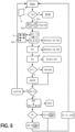
- Figure 6 shows a flow chart with a more detailed representation of an embodiment for steps III and IV of Figure 5 . In the individual steps you can see symbols which characterize these steps.
- the procedure begins at a starting point ("Start"), where a basic set G of work packages A12, A2, A3, A4, A5 is available (see e.g. step I in Figure 5 ).
- Start a starting point
- the procedure always returns to this starting point, always considering a current basic quantity (reduced by work packages already assigned).
- ⁇ Ax a check is made to see whether there is still a work package Ax for which the following steps have not yet been completed. If there is none ("x”), the program ends; if there is still one, the following steps are completed. The procedure therefore runs through all work packages Ax of the basic set G.
- the completion times T1, T2 of the irradiation resources 21a, 21b are determined and compared with each other.
- T1 is smaller than T2 (which can change with each new run) and the irradiation resource 21b that has the completion time T1 is selected here (small arrow in the box).
- the irradiation resource 21a, 21b with the shortest completion time, i.e. with the earliest completion time, is always selected.
- a list can be kept in which the work packages that have already been assigned are assigned to their expected completion time. Work packages that are removed from the graph are also removed from this list so that no further attempts are made to delete this work item from the graph in a subsequent run.
- On the right is an example of a filled selection set AM with the set elements ⁇ A1, A3, A5 ⁇ .
- the set of work packages Ax for which all required work packages (rules 1 and 2) have already been completed at that time is determined based on the graph GG.
- rule 3 allocation rules for irradiation resources R3 is used as a filter for the selection set AM, whereby a work package Ax is not included or is removed again if it may not be irradiated by the selected irradiation resource 21b.
- all work packages A1, A2, A3, A4, A5 may be irradiated by all irradiation resources 21a, 21b and the selection set AM remains unchanged.
- the set A' of work packages that may be processed by the irradiation resource according to rule 3 is therefore determined from the selection set AM and this set A' is the new selection set AM.
- the optional rule 4 (assignment rules for a component R4) is used as a filter for the selection set AM.
- the work package A5 could not be included or could be removed again because it is not related to the component in question.
- the subset B is shown, which only includes the elements ⁇ A1, A2 ⁇ and could be the result of rule 4.
- the work packages Ax of the selection set AM are evaluated based on an evaluation rule (see e.g. rule 5).
- work package A3 is selected. This work package A3 could now be assigned to the work package group of the irradiation resource 21b. In the example shown here, however, an additional optimization step takes place beforehand.
- the work packages Ax in question are preferably evaluated according to different criteria, e.g. the distance to the scanner, the position along the smoke exhaust, the distance to the previous work package, the duration and/or number of work packages that the work package in question requires.
- the different criteria are combined to form an evaluation number, and the individual criteria are preferably weighted using selectable factors (weighting factors). The work package with the best evaluation is selected for allocation.
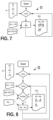
- Figure 7 shows a flow chart of an embodiment for creating a directed graph GG without taking the topology into account.
- the construction of such a dependency graph can be done based on the pure membership in certain areas.
- the input is a list in which layer segments S1, S2, S3 are contained in the desired order. This list can be viewed as an order relation R (see eg Figure 5 in which this procedure could be carried out in step II).
- the individual layer segments Si from this list are now considered.
- Figure 8 shows a flow chart of an embodiment for creating another directed graph GG, in which the relationships are restricted to topologically connected areas. This method could also be used in step II of the Figure 5
- the advantage here is that the number of dependencies between the work packages Ax is reduced, so that there are more options for dividing the work packages Ax among the irradiation resources.
- individual layer segments Si are considered from a list containing layer segments S1, S2, S3 in the desired order and all layer segments Si are traversed in a loop ("b'Si") starting with the second entry in the list.
- irradiation sequence may conflict with the already specified relative order between the work packages. For example, to avoid laser/smoke interactions, it may be required that the work packages are exposed in the opposite direction to the flow direction.
- Figure 9 shows a flow chart of an embodiment for creating another directed graph GG.
- This method could also be used in step II of the Figure 5
- This flow chart describes an algorithm that adds dependencies for work packages in an area potentially shaded by smoke to a directed graph GG, if this does not result in a contradiction.
- the input is a basic set G with all work packages Ax and the directed graph GG, which already contains all mandatory dependencies, e.g. due to the exposure sequence of the layer segments.
- the basic set was made up of Figure 5 used, where one should imagine N work packages Ax, with N»1.
- For each of the N work packages Ax (“VAx”) all work packages Ay are determined that are potentially shadowed by smoke during the exposure of work package Ax.
Landscapes
- Engineering & Computer Science (AREA)
- Materials Engineering (AREA)
- Chemical & Material Sciences (AREA)
- Manufacturing & Machinery (AREA)
- Physics & Mathematics (AREA)
- Toxicology (AREA)
- Health & Medical Sciences (AREA)
- Optics & Photonics (AREA)
- Mechanical Engineering (AREA)
- General Physics & Mathematics (AREA)
- Automation & Control Theory (AREA)
- Microelectronics & Electronic Packaging (AREA)
- Human Computer Interaction (AREA)
- General Health & Medical Sciences (AREA)
- Theoretical Computer Science (AREA)
- Geometry (AREA)
- Mathematical Analysis (AREA)
- Mathematical Optimization (AREA)
- Pure & Applied Mathematics (AREA)
- Computer Hardware Design (AREA)
- Evolutionary Computation (AREA)
- General Engineering & Computer Science (AREA)
- Computational Mathematics (AREA)
- Plasma & Fusion (AREA)
- Powder Metallurgy (AREA)
- Laser Beam Processing (AREA)
Claims (15)
- Procédé de génération d'un jeu de données de commande d'irradiation pour la création de données de commande (PS) pour un dispositif (1) de fabrication additive d'un certain nombre de composants (2) dans un processus de fabrication, lors duquel au moins une couche (S) d'un matériau de construction (13) est introduite dans un espace de processus (3) et le matériau de construction (13) de la couche (S) est consolidé de manière sélective en au moins une couche de composant (BS) par irradiation d'au moins une zone partielle de la couche (S) en utilisant une pluralité de ressources d'irradiation (21a, 21b), comprenant les étapes suivantes :a) la fourniture de données de couche (D) comprenant des données sur la constitution de segments de couche (S1, S2, S3, S4, S5) pour une couche de composant (BS),b) la répartition des données de couche (D) sur plusieurs paquets de travail (A1, A2, A3, A4, A5, A6, A7, A8) en formant une quantité de base (G) des paquets de travail (A1, A2, A3, A4, A5, A6, A7, A8), caractérisé en ce que le procédé comprend en outre les étapes suivantes :c) la mise à disposition d'une relation de séquences (R) définie de manière fixe pour des segments de couche (S1, S2, S3, S4, S5) ou pour les paquets de travail (A1, A2, A3, A4, A5, A6, A7, A8),d) la détermination d'une séquence de traitement des paquets de travail (A1, A2, A3, A4, A5, A6, A7, A8) sur la base au moins de la relation de séquences (R),e) la détermination d'un temps d'exécution (T1, T2) pour chacune des ressources d'irradiation (21a, 21b) pour respectivement le groupe de paquets de travail (AG1, AG2, AG3) des paquets de travail (A1, A2, A3, A4, A5, A6, A7, A8), qui ont déjà été attribués auparavant auxdites ressources d'irradiation (21a, 21b),f) la sélection d'une ressource d'irradiation (21a, 21b) en tenant compte du temps d'exécution (T1, T2) déterminé pour elle, de préférence de la ressource d'irradiation (21a, 21b) ayant le temps d'exécution (T1, T2) déterminé respectivement le plus court,g) la détermination d'un ensemble de sélection (AM) de paquets de travail (A1, A2, A3, A4, A5, A6, A7, A8) à partir de l'ensemble de base (G) des paquets de travail (A1, A2, A3, A4, A5, A6, A7, A8), sur la base de la relation de séquences (R), l'ensemble de sélection (AM) comprenant les paquets de travail (A1, A2, A3, A4, A5, A6, A7, A8) qui peuvent être traités selon la séquence de traitement,h) la sélection d'un paquet de travail (A1, A2, A3, A4, A5, A6, A7, A8) à partir de l'ensemble de sélection (AM) en tenant compte d'une réglementation d'évaluation (BW) prédéfiniei) l'affectation du paquet de travail (A1, A2, A3, A4, A5, A6, A7, A8) sélectionné à un groupe de paquets de travail (AG1, AG2, AG3) affecté à la ressource d'irradiation actuellement sélectionnée (21a, 21b) et le retrait dudit paquet de travail (A1, A2, A3, A4, A5, A6, A7, A8) de l'ensemble de base (G) des paquets de travail (A1, A2, A3, A4, A5, A6, A7, A8),j) la répétition d'au moins les étapes d) à i) jusqu'à un critère d'arrêt prédéterminé.
- Procédé selon la revendication 1, lors duquel les paquets de travail (A1, A2, A3, A4, A5, A6, A7, A8) comprennent en outre des paramètres d'irradiation définis, comprenant en outre les étapes :- de la mise à disposition d'une relation d'affectation pour l'affectation des paramètres d'irradiation à des ressources d'irradiation (21a, 21b),- du filtrage de l'ensemble de sélection des paquets de travail (A1, A2, A3, A4, A5, A6, A7, A8) sur la base de la relation d'affectation et des paramètres d'irradiation affectés en fonction de la ressource d'irradiation (21a, 21b) sélectionnée.
- Procédé selon l'une quelconque des revendications précédentes, lors duquel la règlementation d'évaluation (BW) comprend une évaluation pour au moins un critère du groupe comprenant- la distance spatiale du paquet de travail (A1, A2, A3, A4, A5, A6, A7, A8) par rapport à la ressource d'irradiation sélectionnée (21a, 21b),- le nombre de paquets de travail (A1, A2, A3, A4, A5, A6, A7, A8) dépendant de l'exécution des paquets de travail(A1, A2, A3, A4, A5, A6, A7, A8),- la position du paquet de travail (A1, A2, A3, A4, A5, A6, A7, A8) par rapport à une extension spatiale d'une zone d'évacuation des fumées déterminée ou prédéfinie,- la distance spatiale du paquet de travail (A1, A2, A3, A4, A5, A6, A7, A8) par rapport à un paquet de travail (A1, A2, A3, A4, A5, A6, A7, A8) précédemment affecté,- la durée des paquets de travail (A1, A2, A3, A4, A5, A6, A7, A8) qui présupposent le paquet de travail concerné (A1, A2, A3, A4, A5, A6, A7, A8)- la distance entre les faisceaux des ressources d'irradiation (21a, 21b),de préférence une valeur d'évaluation étant calculée respectivement sur la base de ladite règlementation d'évaluation (BW), la réglementation d'évaluation (BW) étant conçue de telle sorte qu'elle affecte une valeur numérique à au moins un critère,de manière particulièrement préférentielle, des pondérations différentes étant en outre affectées à différents critères et / ou la règlementation d'évaluation (BW) pondérant numériquement de manière différente des critères.
- Procédé selon l'une quelconque des revendications précédentes, lors duquel l'on vérifie si le paquet de travail (A1, A2, A3, A4, A5, A6, A7, A8) sélectionné peut également être irradié par une autre ressource d'irradiation (21a, 21b) et si cette autre ressource d'irradiation (21a, 21b) en ce qui concerne un critère prédéterminé, notamment en ce qui concerne un angle d'incidence ou un angle de déviation d'un faisceau de la ressource d'irradiation (21a, 21b) et / ou une distance spatiale de la ressource d'irradiation (21a, 21b) par rapport au paquet de travail (A1, A2, A3, A4, A5, A6, A7, A8), est mieux adaptée pour exécuter le paquet de travail (A1, A2, A3, A4, A5, A6, A7, A8), dans le cas où l'autre ressource d'irradiation (21a, 21b) est mieux adaptée, l'autre ressource d'irradiation (21a, 21b) devenant la ressource d'irradiation sélectionnée (21a, 21b) et une affectation du paquet de travail (A1, A2, A3, A4, A5, A6, A7, A8) sélectionné à un groupe de paquets de travail (AG1, AG2, AG3), qui est affecté à ladite ressource d'irradiation actuellement sélectionnée (21a, 21b), ayant lieu,
de préférence les temps d'exécution (T1, T2) des ressources d'irradiation (21a, 21b) concernées étant comparés entre eux sans le paquet de travail (A1, A2, A3, A4, A5, A6, A7, A8) concerné et un changement de la ressource d'irradiation (21a, 21b) sélectionnée ayant lieu dans le cas où les temps d'exécution (T1, T2) concernés diffèrent au maximum d'un laps de temps prédéterminé. - Procédé selon l'une quelconque des revendications précédentes, la règlementation d'évaluation (BW) comprenant une fonction de coûts et l'évaluation, en particulier des valeurs d'évaluation des paquets de travail (A1, A2, A3, A4, A5, A6, A7, A8) étant déterminée au cours d'une optimisation de ladite fonction de coûts,de préférence, ladite fonction de coût comprenant- un délai d'achèvement et / ou- les temps d'exécution (T1, T2) et / ou- des critères et / ou une affectation de pertinence selon la revendication 3, et / ou- un critère prédéterminé selon la revendication 4etde préférence, l'évaluation, en particulier une détermination des valeurs d'évaluation, étant effectuée au moyen d'une optimisation itérative d'un plan de déroulement, notamment du temps d'achèvement.
- Procédé selon l'une quelconque des revendications précédentes, lors duquel la détermination de la séquence de traitement des paquets de travail (A1, A2, A3, A4, A5, A6, A7, A8) s'effectue en outre conformément à une consigne d'utilisateur,et ne sont prises en compte de préférence que les consignes de l'utilisateur qui satisfont à la relation de séquence (R),de préférence, la consigne de l'utilisateur comprenant une consigne pour une direction d'avance et / ou une consigne pour une affectation d'une ressource d'irradiation (21a, 21b) à un composant (2).
- Procédé selon l'une quelconque des revendications précédentes, comprenant les étapes:- de la détermination si des paquets de travail (A1, A2, A3, A4, A5, A6, A7, A8) de l'ensemble de sélection (AM) et des paquets de travail (A1, A2, A3, A4, A5, A6, A7, A8) déjà affectés à la ressource d'irradiation (21a, 21b) actuellement sélectionnée présentent une appartenance au même composant (2),et si le cas se présente,- de la création d'un nouvel ensemble de sélection (AM) comprenant les paquets de travail déterminés (A1, A2, A3, A4, A5, A6, A7, A8) de l'ensemble de sélection (AM), qui présentent l'appartenance concernée.
- Procédé selon l'une quelconque des revendications précédentes, lors duquel, pour déterminer la séquence de traitement, les paquets de travail (A1, A2, A3, A4, A5, A6, A7, A8) sont classés dans un graphe (GG) unidirectionnel sur la base de la relation de séquence (R) et lors duquel, lors de la détermination de l'ensemble de sélection (AM) de paquets de travail (A1, A2, A3, A4, A5, A6, A7, A8) à partir de l'ensemble de base (G) de paquets de travail (A1, A2, A3, A4, A5, A6, A7, A8), l'on n'utilise de préférence que les paquets de travail (A1, A2, A3, A4, A5, A6, A7, A8) pour le traitement desquels aucun paquet de travail (A1, A2, A3, A4, A5, A6, A7, A8) du graphe (GG) ne doit être traité auparavant,
de préférence, l'ensemble de base (G) des paquets de travail (A1, A2, A3, A4, A5, A6, A7, A8) étant le graphe orienté (GG) ou comprenant celui-ci. - Procédé selon l'une quelconque des revendications précédentes, lors duquel, dans le cas où aucun paquet de travail (A1, A2, A3, A4, A5, A6, A7, A8) ne peut être trouvé pour la ressource d'irradiation (21a, 21b) sélectionnée, mais des paquets de travail (A1, A2, A3, A4, A5, A6, A7, A8) non encore traités sont présents, un temps d'attente prédéterminé (TW) est affecté à ladite ressource d'irradiation sélectionnée (21a, 21b) en remplacement d'un paquet de travail (A1, A2, A3, A4, A5, A6, A7, A8).
- Ensemble de données de contrôle d'irradiation qui a été généré au moyen d'un procédé selon l'une quelconque des revendications précédentes.
- Procédé de fabrication additive d'au moins une couche de composant d'au moins un composant (31), comprenant les étapes :- de l'introduction d'une couche (S) d'un matériau de construction (13) dans un espace de processus (3) ;- de la consolidation sélective du matériau de construction (13) de la couche (S) par irradiation d'au moins une zone partielle de la couche (S) au moyen d'une pluralité de ressources d'irradiation (21a, 21b),- de la commande des ressources d'irradiation (21a, 21b) au moyen de données de commande (PS) qui ont été générées en utilisant un ensemble de données de commande d'irradiation selon la revendication 10.
- Dispositif de génération de données de commande (100) pour la génération d'un jeu de données de commande d'irradiation pour la création de données de commande (PS) pour un dispositif (1) de fabrication additive d'au moins un certain nombre de composants (2) dans un processus de fabrication, lors duquel au moins une couche (S) d'un matériau de construction (13) est introduite dans un espace de processus (3) et le matériau de construction (13) de la couche (S) est consolidé de manière sélective en des couches de composants (BS) par irradiation d'au moins une zone partielle de la couche (S) en utilisant une pluralité de ressources d'irradiation (21a, 21b),
comprenant une unité d'affectation (101) conçue pour :a) le traitement de données de couche (D) mises à disposition, comprenant des données pour la construction de segments de couche (S1, S2, S3, S4, S5) pour une couche de composant (BS),b) la répartition des données de couche (D) sur plusieurs paquets de travail (A1, A2, A3, A4, A5, A6, A7, A8) en formant une quantité de base (G) des paquets de travail (A1, A2, A3, A4, A5, A6, A7, A8), caractérisé en ce que l'unité d'affectation (101) est en outre conçue pour :c) la mise à disposition d'une relation de séquence (R) fixement définie pour des segments de couche (S1, S2, S3, S4, S5) ou pour les paquets de travail (A1, A2, A3, A4, A5, A6, A7, A8),d) la fixation d'une séquence de traitement des paquets de travail (A1, A2, A3, A4, A5, A6, A7, A8) sur la base au moins de la relation de séquences (R),e) la détermination d'un temps d'exécution (T1, T2) pour chacune des ressources d'irradiation (21a, 21b) pour respectivement le groupe de paquets de travail (AG1, AG2, AG3) des paquets de travail (A1, A2, A3, A4, A5, A6, A7, A8) qui ont déjà été affectés auparavant auxdites ressources d'irradiation (21a, 21b),f) la sélection d'une ressource d'irradiation (21a, 21b) en tenant compte du temps d'exécution (T1, T2) qui a été déterminé pour elle, de préférence de la ressource d'irradiation (21a, 21b) ayant le temps d'exécution (T1, T2) déterminé respectivement le plus court,g) la détermination d'un ensemble de sélection (AM) de paquets de travail (A1, A2, A3, A4, A5, A6, A7, A8) à partir de l'ensemble de base (G) des paquets de travail (A1, A2, A3, A4, A5, A6, A7, A8), sur la base de la relation de séquence (R), l'ensemble de sélection (AM) comprenant les paquets de travail (A1, A2, A3, A4, A5, A6, A7, A8) qui peuvent être traités selon la séquence de traitement,h) la sélection d'un paquet de travail (A1, A2, A3, A4, A5, A6, A7, A8) dans l'ensemble de sélection (AM) en tenant compte d'une réglementation d'évaluation (BW) prédéfinie,i) l'affectation du paquet de travail (A1, A2, A3, A4, A5, A6, A7, A8) sélectionné à un groupe de paquets de travail (AG1, AG2, AG3) qui est affecté à la ressource d'irradiation (21a, 21b) actuellement sélectionnée et le retrait dudit paquet de travail (A1, A2, A3, A4, A5, A6, A7, A8) de l'ensemble de base (G) des paquets de travail (A1, A2, A3, A4, A5, A6, A7, A8),j) la répétition d'au moins les étapes d) à i) jusqu'à un critère d'arrêt prédéterminé. - Dispositif (1) pour la fabrication additive d'au moins une couche de composant (SB) d'au moins un composant (2) dans un processus de fabrication additive, pourvu d'au moins un dispositif d'alimentation pour l'introduction d'une couche (S) d'un matériau de construction (13) dans un espace de processus (3), d'une pluralité de ressources d'irradiation (21a, 21b) pour la consolidation sélective du matériau de construction de la couche par irradiation d'au moins une zone partielle de la couche ainsi que d'un dispositif de génération de données de commande (100) selon la revendication 12.
- Données de commande (PS), destinées à commander un dispositif de fabrication additive (1), les données de commande (PS) ayant été générées en utilisant un ensemble de données de commande d'irradiation selon la revendication 10.
- Produit de programme d'ordinateur pourvu d'un programme d'ordinateur pouvant être chargé directement dans un dispositif de mémoire d'un dispositif de génération de données de commande (100) et/ou d'un dispositif de commande (30) d'un dispositif (1) pour la fabrication additive d'une couche de composant d'un composant (2), avec des sections de programme destinées à exécuter toutes les étapes du procédé selon l'une des revendications 1 à 9, lorsque le programme d'ordinateur est exécuté dans le dispositif de génération de données de commande (100) et/ou dans le dispositif de commande (30).
Applications Claiming Priority (1)
| Application Number | Priority Date | Filing Date | Title |
|---|---|---|---|
| DE102020115208.6A DE102020115208A1 (de) | 2020-06-08 | 2020-06-08 | Verfahren zur Generierung eines Bestrahlungssteuerdatensatzes für eine Vorrichtung zur additiven Fertigung |
Publications (3)
| Publication Number | Publication Date |
|---|---|
| EP3922440A1 EP3922440A1 (fr) | 2021-12-15 |
| EP3922440C0 EP3922440C0 (fr) | 2024-10-16 |
| EP3922440B1 true EP3922440B1 (fr) | 2024-10-16 |
Family
ID=76325377
Family Applications (1)
| Application Number | Title | Priority Date | Filing Date |
|---|---|---|---|
| EP21178097.8A Active EP3922440B1 (fr) | 2020-06-08 | 2021-06-07 | Procédé de génération d'un ensemble de données de commande de rayonnement pour un dispositif de fabrication additive |
Country Status (3)
| Country | Link |
|---|---|
| US (1) | US12186991B2 (fr) |
| EP (1) | EP3922440B1 (fr) |
| DE (1) | DE102020115208A1 (fr) |
Families Citing this family (7)
| Publication number | Priority date | Publication date | Assignee | Title |
|---|---|---|---|---|
| US20220284154A1 (en) * | 2021-02-09 | 2022-09-08 | Nutech Ventures | Thermal modeling of additive manufacturing using progressive horizontal subsections |
| US20230234138A1 (en) * | 2022-01-27 | 2023-07-27 | Freeform Future Corp. | Scheduling lasing tasks of a 3d printing system |
| DE102022108550A1 (de) | 2022-04-08 | 2023-10-12 | Trumpf Laser- Und Systemtechnik Gmbh | Verfahren zur schichtweisen Fertigung einer Vielzahl von Objekten und entsprechendes Planungsverfahren, mit volumenbasierter Aufteilung der Objekte auf Teilbereiche der Bauplattform |
| CN114932682A (zh) * | 2022-06-30 | 2022-08-23 | 深圳市智能派科技有限公司 | 一种实时监测光固化打印机的方法和系统 |
| WO2025056949A1 (fr) * | 2023-09-13 | 2025-03-20 | Arcelormittal | Procédé de détermination de données d'attribution de faisceau à région pour un dispositif de fabrication par fusion de faisceau à lit de poudre |
| DE102024118073A1 (de) * | 2024-06-26 | 2025-12-31 | TRUMPF Laser- und Systemtechnik SE | Verfahren und Planungsvorrichtung zum Planen einer lokal selektiven Bestrahlung eines Arbeitsbereichs mit einer Mehrzahl an Energiestrahlen, Verfahren und Fertigungsvorrichtung zum additiven Fertigen eines Bauteils aus einem Pulvermaterial und Computerprogramm |
| DE102024131619A1 (de) * | 2024-10-30 | 2026-04-30 | TRUMPF Laser- und Systemtechnik SE | Verfahren und Planungsvorrichtung zum Planen einer lokal selektiven Bestrahlung eines Arbeitsbereichs mit einer Mehrzahl an Energiestrahlen, Verfahren und Fertigungsvorrichtung zum additiven Fertigen eines Bauteils aus einem Pulvermaterial und Computerprogramm |
Family Cites Families (7)
| Publication number | Priority date | Publication date | Assignee | Title |
|---|---|---|---|---|
| US9636871B2 (en) | 2013-08-21 | 2017-05-02 | Microsoft Technology Licensing, Llc | Optimizing 3D printing using segmentation or aggregation |
| US20180272611A1 (en) | 2015-01-07 | 2018-09-27 | Eos Gmbh Electro Optical Systems | Device and generative layer-building process for producing a three-dimensional object by multiple beams |
| US10635368B2 (en) | 2016-06-28 | 2020-04-28 | Hewlett-Packard Development Company, L.P. | Management of 3D printing |
| DE102016223980B4 (de) * | 2016-12-01 | 2022-09-22 | Adidas Ag | Verfahren zur Herstellung eines Kunststoffformteils |
| DE102017205051A1 (de) | 2017-03-24 | 2018-09-27 | Eos Gmbh Electro Optical Systems | Überlappoptimierung |
| DE102017205053A1 (de) | 2017-03-24 | 2018-09-27 | Eos Gmbh Electro Optical Systems | Belichtungsstrategie in Mehrstrahl-AM-Systemen |
| WO2021080587A1 (fr) * | 2019-10-24 | 2021-04-29 | Hewlett-Packard Development Company, L.P. | Machines de fabrication additive comprenant des sources d'énergie focalisées et non focalisées |
-
2020
- 2020-06-08 DE DE102020115208.6A patent/DE102020115208A1/de active Pending
-
2021
- 2021-06-02 US US17/336,463 patent/US12186991B2/en active Active
- 2021-06-07 EP EP21178097.8A patent/EP3922440B1/fr active Active
Also Published As
| Publication number | Publication date |
|---|---|
| DE102020115208A1 (de) | 2021-12-09 |
| US20210379832A1 (en) | 2021-12-09 |
| US12186991B2 (en) | 2025-01-07 |
| EP3922440A1 (fr) | 2021-12-15 |
| EP3922440C0 (fr) | 2024-10-16 |
Similar Documents
| Publication | Publication Date | Title |
|---|---|---|
| EP3922440B1 (fr) | Procédé de génération d'un ensemble de données de commande de rayonnement pour un dispositif de fabrication additive | |
| EP2785481B1 (fr) | Procédé de fabrication d'un corps façonné par montage en couches de matière en poudre | |
| EP3582953B1 (fr) | Dispositif et procédé de fabrication générative d'un objet tridimensionnel | |
| EP3285944B1 (fr) | Dispositif, procédé et unité de commande pour la fabrication générative d'un objet tridimensionnel | |
| DE102017108534A1 (de) | Kontrolle eines additiven Fertigungsprozesses | |
| EP3318352A1 (fr) | Procédé de détection basé sur la simulation de zones de composants thermiquement critiques et procédé d'adaptation spécifique aux composants d'une génération de chaleur locale lors de la fabrication additive | |
| WO2018172080A1 (fr) | Stratégie d'exposition dans des systèmes de fabrication additive (am) à faisceaux multiples | |
| WO2018197443A1 (fr) | Homogénéisation de l'apport énergétique | |
| EP3710183A1 (fr) | Tri de bandes d'irradiation | |
| DE112019007356B4 (de) | Numerische Steuerung und Verfahren zum Steuern einer additiven Herstellungsvorrichtung | |
| WO2018167024A1 (fr) | Procédé pour la détermination de valeurs de paramètres de processus d'impression, procédé pour la commande d'une imprimante 3d, support de stockage lisible par ordinateur et imprimante 3d | |
| WO2019158303A1 (fr) | Procédé de fabrication additive à solidification contrôlée et dispositif associé | |
| WO2018210436A1 (fr) | Optimisation de l'introduction d'énergie dans la couche inférieure | |
| DE102007057450A1 (de) | Verfahren und Vorrichtung zur Herstellung eines dreidimensionalen Gegenstandes aus einem verfestigbaren Material | |
| WO2018172079A1 (fr) | Optimisation de chevauchement | |
| EP3488305A1 (fr) | Procédé et dispositif de détermination de la qualité d'un composant | |
| EP4619183A1 (fr) | Procédé de fourniture d'une instruction de processus pour la fabrication additive, au moyen d'un apprentissage automatique | |
| WO2018206581A1 (fr) | Entrée d'énergie spécifique à la position | |
| WO2023078762A1 (fr) | Procédé, dispositif de planification et produit-programme informatique de planification d'une exposition localement sélective d'une zone de travail au rayonnement d'un faisceau d'énergie, et procédé, dispositif de production et produit-programme informatique pour la fabrication additive de composants à partir d'un matériau en poudre | |
| EP3807031B1 (fr) | Calcul de trajets d'exposition à faible distorsion des pièces | |
| EP4532128A1 (fr) | Procédé et dispositif pour générer des données de commande pour un dispositif pour fabriquer un composant de manière additive | |
| DE102021127580A1 (de) | Verfahren zum Definieren einer Mehrzahl von Bestrahlungsvektoren | |
| EP3752346A1 (fr) | Post-exposition sélective | |
| DE102020201896A1 (de) | Fertigungssystem für die Verwendung in einem additiven und pulverbettbasierten Fertigungsverfahren zur Herstellung von dreidimensionalen Objekten, Verfahren zur Durchführung von simultanen Beschichtungs- und Verfestigungsvorgängen | |
| WO2025087771A1 (fr) | Procédé et dispositif de planification pour planifier une irradiation localement sélective d'une région de travail en utilisant un faisceau d'énergie, procédé et dispositif de fabrication pour la fabrication additive d'un composant à partir d'un matériau pulvérulent |
Legal Events
| Date | Code | Title | Description |
|---|---|---|---|
| PUAI | Public reference made under article 153(3) epc to a published international application that has entered the european phase |
Free format text: ORIGINAL CODE: 0009012 |
|
| STAA | Information on the status of an ep patent application or granted ep patent |
Free format text: STATUS: THE APPLICATION HAS BEEN PUBLISHED |
|
| AK | Designated contracting states |
Kind code of ref document: A1 Designated state(s): AL AT BE BG CH CY CZ DE DK EE ES FI FR GB GR HR HU IE IS IT LI LT LU LV MC MK MT NL NO PL PT RO RS SE SI SK SM TR |
|
| B565 | Issuance of search results under rule 164(2) epc |
Effective date: 20211111 |
|
| STAA | Information on the status of an ep patent application or granted ep patent |
Free format text: STATUS: REQUEST FOR EXAMINATION WAS MADE |
|
| 17P | Request for examination filed |
Effective date: 20220124 |
|
| RBV | Designated contracting states (corrected) |
Designated state(s): AL AT BE BG CH CY CZ DE DK EE ES FI FR GB GR HR HU IE IS IT LI LT LU LV MC MK MT NL NO PL PT RO RS SE SI SK SM TR |
|
| GRAP | Despatch of communication of intention to grant a patent |
Free format text: ORIGINAL CODE: EPIDOSNIGR1 |
|
| STAA | Information on the status of an ep patent application or granted ep patent |
Free format text: STATUS: GRANT OF PATENT IS INTENDED |
|
| INTG | Intention to grant announced |
Effective date: 20230706 |
|
| GRAJ | Information related to disapproval of communication of intention to grant by the applicant or resumption of examination proceedings by the epo deleted |
Free format text: ORIGINAL CODE: EPIDOSDIGR1 |
|
| STAA | Information on the status of an ep patent application or granted ep patent |
Free format text: STATUS: REQUEST FOR EXAMINATION WAS MADE |
|
| STAA | Information on the status of an ep patent application or granted ep patent |
Free format text: STATUS: EXAMINATION IS IN PROGRESS |
|
| INTC | Intention to grant announced (deleted) | ||
| 17Q | First examination report despatched |
Effective date: 20231109 |
|
| GRAP | Despatch of communication of intention to grant a patent |
Free format text: ORIGINAL CODE: EPIDOSNIGR1 |
|
| STAA | Information on the status of an ep patent application or granted ep patent |
Free format text: STATUS: GRANT OF PATENT IS INTENDED |
|
| INTG | Intention to grant announced |
Effective date: 20240516 |
|
| GRAS | Grant fee paid |
Free format text: ORIGINAL CODE: EPIDOSNIGR3 |
|
| GRAA | (expected) grant |
Free format text: ORIGINAL CODE: 0009210 |
|
| STAA | Information on the status of an ep patent application or granted ep patent |
Free format text: STATUS: THE PATENT HAS BEEN GRANTED |
|
| AK | Designated contracting states |
Kind code of ref document: B1 Designated state(s): AL AT BE BG CH CY CZ DE DK EE ES FI FR GB GR HR HU IE IS IT LI LT LU LV MC MK MT NL NO PL PT RO RS SE SI SK SM TR |
|
| REG | Reference to a national code |
Ref country code: GB Ref legal event code: FG4D Free format text: NOT ENGLISH |
|
| REG | Reference to a national code |
Ref country code: CH Ref legal event code: EP |
|
| REG | Reference to a national code |
Ref country code: IE Ref legal event code: FG4D Free format text: LANGUAGE OF EP DOCUMENT: GERMAN |
|
| REG | Reference to a national code |
Ref country code: DE Ref legal event code: R096 Ref document number: 502021005486 Country of ref document: DE |
|
| U01 | Request for unitary effect filed |
Effective date: 20241030 |
|
| U07 | Unitary effect registered |
Designated state(s): AT BE BG DE DK EE FI FR IT LT LU LV MT NL PT RO SE SI Effective date: 20241111 |
|
| PG25 | Lapsed in a contracting state [announced via postgrant information from national office to epo] |
Ref country code: IS Free format text: LAPSE BECAUSE OF FAILURE TO SUBMIT A TRANSLATION OF THE DESCRIPTION OR TO PAY THE FEE WITHIN THE PRESCRIBED TIME-LIMIT Effective date: 20250216 Ref country code: HR Free format text: LAPSE BECAUSE OF FAILURE TO SUBMIT A TRANSLATION OF THE DESCRIPTION OR TO PAY THE FEE WITHIN THE PRESCRIBED TIME-LIMIT Effective date: 20241016 |
|
| PG25 | Lapsed in a contracting state [announced via postgrant information from national office to epo] |
Ref country code: ES Free format text: LAPSE BECAUSE OF FAILURE TO SUBMIT A TRANSLATION OF THE DESCRIPTION OR TO PAY THE FEE WITHIN THE PRESCRIBED TIME-LIMIT Effective date: 20241016 |
|
| PG25 | Lapsed in a contracting state [announced via postgrant information from national office to epo] |
Ref country code: NO Free format text: LAPSE BECAUSE OF FAILURE TO SUBMIT A TRANSLATION OF THE DESCRIPTION OR TO PAY THE FEE WITHIN THE PRESCRIBED TIME-LIMIT Effective date: 20250116 |
|
| PG25 | Lapsed in a contracting state [announced via postgrant information from national office to epo] |
Ref country code: GR Free format text: LAPSE BECAUSE OF FAILURE TO SUBMIT A TRANSLATION OF THE DESCRIPTION OR TO PAY THE FEE WITHIN THE PRESCRIBED TIME-LIMIT Effective date: 20250117 |
|
| PG25 | Lapsed in a contracting state [announced via postgrant information from national office to epo] |
Ref country code: PL Free format text: LAPSE BECAUSE OF FAILURE TO SUBMIT A TRANSLATION OF THE DESCRIPTION OR TO PAY THE FEE WITHIN THE PRESCRIBED TIME-LIMIT Effective date: 20241016 |
|
| PG25 | Lapsed in a contracting state [announced via postgrant information from national office to epo] |
Ref country code: RS Free format text: LAPSE BECAUSE OF FAILURE TO SUBMIT A TRANSLATION OF THE DESCRIPTION OR TO PAY THE FEE WITHIN THE PRESCRIBED TIME-LIMIT Effective date: 20250116 |
|
| PG25 | Lapsed in a contracting state [announced via postgrant information from national office to epo] |
Ref country code: SM Free format text: LAPSE BECAUSE OF FAILURE TO SUBMIT A TRANSLATION OF THE DESCRIPTION OR TO PAY THE FEE WITHIN THE PRESCRIBED TIME-LIMIT Effective date: 20241016 |
|
| PGFP | Annual fee paid to national office [announced via postgrant information from national office to epo] |
Ref country code: GB Payment date: 20250618 Year of fee payment: 5 |
|
| PG25 | Lapsed in a contracting state [announced via postgrant information from national office to epo] |
Ref country code: SK Free format text: LAPSE BECAUSE OF FAILURE TO SUBMIT A TRANSLATION OF THE DESCRIPTION OR TO PAY THE FEE WITHIN THE PRESCRIBED TIME-LIMIT Effective date: 20241016 |
|
| PG25 | Lapsed in a contracting state [announced via postgrant information from national office to epo] |
Ref country code: CZ Free format text: LAPSE BECAUSE OF FAILURE TO SUBMIT A TRANSLATION OF THE DESCRIPTION OR TO PAY THE FEE WITHIN THE PRESCRIBED TIME-LIMIT Effective date: 20241016 |
|
| U20 | Renewal fee for the european patent with unitary effect paid |
Year of fee payment: 5 Effective date: 20250627 |
|
| PLBE | No opposition filed within time limit |
Free format text: ORIGINAL CODE: 0009261 |
|
| STAA | Information on the status of an ep patent application or granted ep patent |
Free format text: STATUS: NO OPPOSITION FILED WITHIN TIME LIMIT |
|
| 26N | No opposition filed |
Effective date: 20250717 |
|
| REG | Reference to a national code |
Ref country code: CH Ref legal event code: H13 Free format text: ST27 STATUS EVENT CODE: U-0-0-H10-H13 (AS PROVIDED BY THE NATIONAL OFFICE) Effective date: 20260127 |
|
| PG25 | Lapsed in a contracting state [announced via postgrant information from national office to epo] |
Ref country code: MC Free format text: LAPSE BECAUSE OF FAILURE TO SUBMIT A TRANSLATION OF THE DESCRIPTION OR TO PAY THE FEE WITHIN THE PRESCRIBED TIME-LIMIT Effective date: 20241016 |
|
| PG25 | Lapsed in a contracting state [announced via postgrant information from national office to epo] |
Ref country code: IE Free format text: LAPSE BECAUSE OF NON-PAYMENT OF DUE FEES Effective date: 20250607 |
|
| PG25 | Lapsed in a contracting state [announced via postgrant information from national office to epo] |
Ref country code: CH Free format text: LAPSE BECAUSE OF NON-PAYMENT OF DUE FEES Effective date: 20250630 |