EP3923007B1 - Batterieverwaltungsvorrichtung, batterieverwaltungsverfahren, batteriepack und elektrofahrzeug - Google Patents
Batterieverwaltungsvorrichtung, batterieverwaltungsverfahren, batteriepack und elektrofahrzeug Download PDFInfo
- Publication number
- EP3923007B1 EP3923007B1 EP20861336.4A EP20861336A EP3923007B1 EP 3923007 B1 EP3923007 B1 EP 3923007B1 EP 20861336 A EP20861336 A EP 20861336A EP 3923007 B1 EP3923007 B1 EP 3923007B1
- Authority
- EP
- European Patent Office
- Prior art keywords
- soc
- current
- interest
- list
- battery
- Prior art date
- Legal status (The legal status is an assumption and is not a legal conclusion. Google has not performed a legal analysis and makes no representation as to the accuracy of the status listed.)
- Active
Links
Images


Classifications
-
- B—PERFORMING OPERATIONS; TRANSPORTING
- B60—VEHICLES IN GENERAL
- B60L—PROPULSION OF ELECTRICALLY-PROPELLED VEHICLES; SUPPLYING ELECTRIC POWER FOR AUXILIARY EQUIPMENT OF ELECTRICALLY-PROPELLED VEHICLES; ELECTRODYNAMIC BRAKE SYSTEMS FOR VEHICLES IN GENERAL; MAGNETIC SUSPENSION OR LEVITATION FOR VEHICLES; MONITORING OPERATING VARIABLES OF ELECTRICALLY-PROPELLED VEHICLES; ELECTRIC SAFETY DEVICES FOR ELECTRICALLY-PROPELLED VEHICLES
- B60L58/00—Methods or circuit arrangements for monitoring or controlling batteries or fuel cells, specially adapted for electric vehicles
- B60L58/10—Methods or circuit arrangements for monitoring or controlling batteries or fuel cells, specially adapted for electric vehicles for monitoring or controlling batteries
- B60L58/12—Methods or circuit arrangements for monitoring or controlling batteries or fuel cells, specially adapted for electric vehicles for monitoring or controlling batteries responding to state of charge [SoC]
-
- G—PHYSICS
- G01—MEASURING; TESTING
- G01R—MEASURING ELECTRIC VARIABLES; MEASURING MAGNETIC VARIABLES
- G01R31/00—Arrangements for testing electric properties; Arrangements for locating electric faults; Arrangements for electrical testing characterised by what is being tested not provided for elsewhere
- G01R31/36—Arrangements for testing, measuring or monitoring the electrical condition of accumulators or electric batteries, e.g. capacity or state of charge [SoC]
- G01R31/385—Arrangements for measuring battery or accumulator variables
- G01R31/387—Determining ampere-hour charge capacity or SoC
-
- B—PERFORMING OPERATIONS; TRANSPORTING
- B60—VEHICLES IN GENERAL
- B60L—PROPULSION OF ELECTRICALLY-PROPELLED VEHICLES; SUPPLYING ELECTRIC POWER FOR AUXILIARY EQUIPMENT OF ELECTRICALLY-PROPELLED VEHICLES; ELECTRODYNAMIC BRAKE SYSTEMS FOR VEHICLES IN GENERAL; MAGNETIC SUSPENSION OR LEVITATION FOR VEHICLES; MONITORING OPERATING VARIABLES OF ELECTRICALLY-PROPELLED VEHICLES; ELECTRIC SAFETY DEVICES FOR ELECTRICALLY-PROPELLED VEHICLES
- B60L3/00—Electric devices on electrically-propelled vehicles for safety purposes; Monitoring operating variables, e.g. speed, deceleration or energy consumption
- B60L3/0023—Detecting, eliminating, remedying or compensating for drive train abnormalities, e.g. failures within the drive train
- B60L3/0046—Detecting, eliminating, remedying or compensating for drive train abnormalities, e.g. failures within the drive train relating to electric energy storage systems, e.g. batteries or capacitors
-
- B—PERFORMING OPERATIONS; TRANSPORTING
- B60—VEHICLES IN GENERAL
- B60L—PROPULSION OF ELECTRICALLY-PROPELLED VEHICLES; SUPPLYING ELECTRIC POWER FOR AUXILIARY EQUIPMENT OF ELECTRICALLY-PROPELLED VEHICLES; ELECTRODYNAMIC BRAKE SYSTEMS FOR VEHICLES IN GENERAL; MAGNETIC SUSPENSION OR LEVITATION FOR VEHICLES; MONITORING OPERATING VARIABLES OF ELECTRICALLY-PROPELLED VEHICLES; ELECTRIC SAFETY DEVICES FOR ELECTRICALLY-PROPELLED VEHICLES
- B60L53/00—Methods of charging batteries, specially adapted for electric vehicles; Charging stations or on-board charging equipment therefor; Exchange of energy storage elements in electric vehicles
-
- G—PHYSICS
- G01—MEASURING; TESTING
- G01R—MEASURING ELECTRIC VARIABLES; MEASURING MAGNETIC VARIABLES
- G01R31/00—Arrangements for testing electric properties; Arrangements for locating electric faults; Arrangements for electrical testing characterised by what is being tested not provided for elsewhere
- G01R31/36—Arrangements for testing, measuring or monitoring the electrical condition of accumulators or electric batteries, e.g. capacity or state of charge [SoC]
-
- G—PHYSICS
- G01—MEASURING; TESTING
- G01R—MEASURING ELECTRIC VARIABLES; MEASURING MAGNETIC VARIABLES
- G01R31/00—Arrangements for testing electric properties; Arrangements for locating electric faults; Arrangements for electrical testing characterised by what is being tested not provided for elsewhere
- G01R31/36—Arrangements for testing, measuring or monitoring the electrical condition of accumulators or electric batteries, e.g. capacity or state of charge [SoC]
- G01R31/3644—Constructional arrangements
- G01R31/3648—Constructional arrangements comprising digital calculation means, e.g. for performing an algorithm
-
- G—PHYSICS
- G01—MEASURING; TESTING
- G01R—MEASURING ELECTRIC VARIABLES; MEASURING MAGNETIC VARIABLES
- G01R31/00—Arrangements for testing electric properties; Arrangements for locating electric faults; Arrangements for electrical testing characterised by what is being tested not provided for elsewhere
- G01R31/36—Arrangements for testing, measuring or monitoring the electrical condition of accumulators or electric batteries, e.g. capacity or state of charge [SoC]
- G01R31/374—Arrangements for testing, measuring or monitoring the electrical condition of accumulators or electric batteries, e.g. capacity or state of charge [SoC] with means for correcting the measurement for temperature or ageing
-
- G—PHYSICS
- G01—MEASURING; TESTING
- G01R—MEASURING ELECTRIC VARIABLES; MEASURING MAGNETIC VARIABLES
- G01R31/00—Arrangements for testing electric properties; Arrangements for locating electric faults; Arrangements for electrical testing characterised by what is being tested not provided for elsewhere
- G01R31/36—Arrangements for testing, measuring or monitoring the electrical condition of accumulators or electric batteries, e.g. capacity or state of charge [SoC]
- G01R31/382—Arrangements for monitoring battery or accumulator variables, e.g. SoC
- G01R31/3842—Arrangements for monitoring battery or accumulator variables, e.g. SoC combining voltage and current measurements
-
- G—PHYSICS
- G01—MEASURING; TESTING
- G01R—MEASURING ELECTRIC VARIABLES; MEASURING MAGNETIC VARIABLES
- G01R31/00—Arrangements for testing electric properties; Arrangements for locating electric faults; Arrangements for electrical testing characterised by what is being tested not provided for elsewhere
- G01R31/36—Arrangements for testing, measuring or monitoring the electrical condition of accumulators or electric batteries, e.g. capacity or state of charge [SoC]
- G01R31/385—Arrangements for measuring battery or accumulator variables
- G01R31/387—Determining ampere-hour charge capacity or SoC
- G01R31/388—Determining ampere-hour charge capacity or SoC involving voltage measurements
-
- H—ELECTRICITY
- H01—ELECTRIC ELEMENTS
- H01M—PROCESSES OR MEANS, e.g. BATTERIES, FOR THE DIRECT CONVERSION OF CHEMICAL ENERGY INTO ELECTRICAL ENERGY
- H01M10/00—Secondary cells; Manufacture thereof
- H01M10/42—Methods or arrangements for servicing or maintenance of secondary cells or secondary half-cells
- H01M10/425—Structural combination with electronic components, e.g. electronic circuits integrated to the outside of the casing
-
- H—ELECTRICITY
- H01—ELECTRIC ELEMENTS
- H01M—PROCESSES OR MEANS, e.g. BATTERIES, FOR THE DIRECT CONVERSION OF CHEMICAL ENERGY INTO ELECTRICAL ENERGY
- H01M10/00—Secondary cells; Manufacture thereof
- H01M10/42—Methods or arrangements for servicing or maintenance of secondary cells or secondary half-cells
- H01M10/48—Accumulators combined with arrangements for measuring, testing or indicating the condition of cells, e.g. the level or density of the electrolyte
-
- H—ELECTRICITY
- H01—ELECTRIC ELEMENTS
- H01M—PROCESSES OR MEANS, e.g. BATTERIES, FOR THE DIRECT CONVERSION OF CHEMICAL ENERGY INTO ELECTRICAL ENERGY
- H01M10/00—Secondary cells; Manufacture thereof
- H01M10/42—Methods or arrangements for servicing or maintenance of secondary cells or secondary half-cells
- H01M10/48—Accumulators combined with arrangements for measuring, testing or indicating the condition of cells, e.g. the level or density of the electrolyte
- H01M10/486—Accumulators combined with arrangements for measuring, testing or indicating the condition of cells, e.g. the level or density of the electrolyte for measuring temperature
-
- H—ELECTRICITY
- H02—GENERATION; CONVERSION OR DISTRIBUTION OF ELECTRIC POWER
- H02J—ELECTRIC POWER NETWORKS; CIRCUIT ARRANGEMENTS OR SYSTEMS FOR SUPPLYING OR DISTRIBUTING ELECTRIC POWER; SYSTEMS FOR STORING ELECTRIC ENERGY
- H02J7/00—Circuit arrangements for charging or discharging batteries or for supplying loads from batteries
- H02J7/80—Circuit arrangements for charging or discharging batteries or for supplying loads from batteries including monitoring or indicating arrangements
- H02J7/82—Control of state of charge [SOC]
-
- B—PERFORMING OPERATIONS; TRANSPORTING
- B60—VEHICLES IN GENERAL
- B60L—PROPULSION OF ELECTRICALLY-PROPELLED VEHICLES; SUPPLYING ELECTRIC POWER FOR AUXILIARY EQUIPMENT OF ELECTRICALLY-PROPELLED VEHICLES; ELECTRODYNAMIC BRAKE SYSTEMS FOR VEHICLES IN GENERAL; MAGNETIC SUSPENSION OR LEVITATION FOR VEHICLES; MONITORING OPERATING VARIABLES OF ELECTRICALLY-PROPELLED VEHICLES; ELECTRIC SAFETY DEVICES FOR ELECTRICALLY-PROPELLED VEHICLES
- B60L2240/00—Control parameters of input or output; Target parameters
- B60L2240/40—Drive Train control parameters
- B60L2240/54—Drive Train control parameters related to batteries
- B60L2240/545—Temperature
-
- B—PERFORMING OPERATIONS; TRANSPORTING
- B60—VEHICLES IN GENERAL
- B60L—PROPULSION OF ELECTRICALLY-PROPELLED VEHICLES; SUPPLYING ELECTRIC POWER FOR AUXILIARY EQUIPMENT OF ELECTRICALLY-PROPELLED VEHICLES; ELECTRODYNAMIC BRAKE SYSTEMS FOR VEHICLES IN GENERAL; MAGNETIC SUSPENSION OR LEVITATION FOR VEHICLES; MONITORING OPERATING VARIABLES OF ELECTRICALLY-PROPELLED VEHICLES; ELECTRIC SAFETY DEVICES FOR ELECTRICALLY-PROPELLED VEHICLES
- B60L2240/00—Control parameters of input or output; Target parameters
- B60L2240/40—Drive Train control parameters
- B60L2240/54—Drive Train control parameters related to batteries
- B60L2240/547—Voltage
-
- B—PERFORMING OPERATIONS; TRANSPORTING
- B60—VEHICLES IN GENERAL
- B60L—PROPULSION OF ELECTRICALLY-PROPELLED VEHICLES; SUPPLYING ELECTRIC POWER FOR AUXILIARY EQUIPMENT OF ELECTRICALLY-PROPELLED VEHICLES; ELECTRODYNAMIC BRAKE SYSTEMS FOR VEHICLES IN GENERAL; MAGNETIC SUSPENSION OR LEVITATION FOR VEHICLES; MONITORING OPERATING VARIABLES OF ELECTRICALLY-PROPELLED VEHICLES; ELECTRIC SAFETY DEVICES FOR ELECTRICALLY-PROPELLED VEHICLES
- B60L2240/00—Control parameters of input or output; Target parameters
- B60L2240/40—Drive Train control parameters
- B60L2240/54—Drive Train control parameters related to batteries
- B60L2240/549—Current
-
- B—PERFORMING OPERATIONS; TRANSPORTING
- B60—VEHICLES IN GENERAL
- B60Y—INDEXING SCHEME RELATING TO ASPECTS CROSS-CUTTING VEHICLE TECHNOLOGY
- B60Y2200/00—Type of vehicle
- B60Y2200/90—Vehicles comprising electric prime movers
- B60Y2200/91—Electric vehicles
-
- H—ELECTRICITY
- H01—ELECTRIC ELEMENTS
- H01M—PROCESSES OR MEANS, e.g. BATTERIES, FOR THE DIRECT CONVERSION OF CHEMICAL ENERGY INTO ELECTRICAL ENERGY
- H01M10/00—Secondary cells; Manufacture thereof
- H01M10/42—Methods or arrangements for servicing or maintenance of secondary cells or secondary half-cells
- H01M10/425—Structural combination with electronic components, e.g. electronic circuits integrated to the outside of the casing
- H01M2010/4271—Battery management systems including electronic circuits, e.g. control of current or voltage to keep battery in healthy state, cell balancing
-
- H—ELECTRICITY
- H01—ELECTRIC ELEMENTS
- H01M—PROCESSES OR MEANS, e.g. BATTERIES, FOR THE DIRECT CONVERSION OF CHEMICAL ENERGY INTO ELECTRICAL ENERGY
- H01M2220/00—Batteries for particular applications
- H01M2220/20—Batteries in motive systems, e.g. vehicle, ship, plane
-
- H—ELECTRICITY
- H02—GENERATION; CONVERSION OR DISTRIBUTION OF ELECTRIC POWER
- H02J—ELECTRIC POWER NETWORKS; CIRCUIT ARRANGEMENTS OR SYSTEMS FOR SUPPLYING OR DISTRIBUTING ELECTRIC POWER; SYSTEMS FOR STORING ELECTRIC ENERGY
- H02J7/00—Circuit arrangements for charging or discharging batteries or for supplying loads from batteries
- H02J7/90—Regulation of charging or discharging current or voltage
- H02J7/933—Regulation of charging or discharging current or voltage the cycle being controlled or terminated in response to electric parameters
-
- Y—GENERAL TAGGING OF NEW TECHNOLOGICAL DEVELOPMENTS; GENERAL TAGGING OF CROSS-SECTIONAL TECHNOLOGIES SPANNING OVER SEVERAL SECTIONS OF THE IPC; TECHNICAL SUBJECTS COVERED BY FORMER USPC CROSS-REFERENCE ART COLLECTIONS [XRACs] AND DIGESTS
- Y02—TECHNOLOGIES OR APPLICATIONS FOR MITIGATION OR ADAPTATION AGAINST CLIMATE CHANGE
- Y02E—REDUCTION OF GREENHOUSE GAS [GHG] EMISSIONS, RELATED TO ENERGY GENERATION, TRANSMISSION OR DISTRIBUTION
- Y02E60/00—Enabling technologies; Technologies with a potential or indirect contribution to GHG emissions mitigation
- Y02E60/10—Energy storage using batteries
-
- Y—GENERAL TAGGING OF NEW TECHNOLOGICAL DEVELOPMENTS; GENERAL TAGGING OF CROSS-SECTIONAL TECHNOLOGIES SPANNING OVER SEVERAL SECTIONS OF THE IPC; TECHNICAL SUBJECTS COVERED BY FORMER USPC CROSS-REFERENCE ART COLLECTIONS [XRACs] AND DIGESTS
- Y02—TECHNOLOGIES OR APPLICATIONS FOR MITIGATION OR ADAPTATION AGAINST CLIMATE CHANGE
- Y02T—CLIMATE CHANGE MITIGATION TECHNOLOGIES RELATED TO TRANSPORTATION
- Y02T10/00—Road transport of goods or passengers
- Y02T10/60—Other road transportation technologies with climate change mitigation effect
- Y02T10/70—Energy storage systems for electromobility, e.g. batteries
-
- Y—GENERAL TAGGING OF NEW TECHNOLOGICAL DEVELOPMENTS; GENERAL TAGGING OF CROSS-SECTIONAL TECHNOLOGIES SPANNING OVER SEVERAL SECTIONS OF THE IPC; TECHNICAL SUBJECTS COVERED BY FORMER USPC CROSS-REFERENCE ART COLLECTIONS [XRACs] AND DIGESTS
- Y02—TECHNOLOGIES OR APPLICATIONS FOR MITIGATION OR ADAPTATION AGAINST CLIMATE CHANGE
- Y02T—CLIMATE CHANGE MITIGATION TECHNOLOGIES RELATED TO TRANSPORTATION
- Y02T10/00—Road transport of goods or passengers
- Y02T10/60—Other road transportation technologies with climate change mitigation effect
- Y02T10/7072—Electromobility specific charging systems or methods for batteries, ultracapacitors, supercapacitors or double-layer capacitors
-
- Y—GENERAL TAGGING OF NEW TECHNOLOGICAL DEVELOPMENTS; GENERAL TAGGING OF CROSS-SECTIONAL TECHNOLOGIES SPANNING OVER SEVERAL SECTIONS OF THE IPC; TECHNICAL SUBJECTS COVERED BY FORMER USPC CROSS-REFERENCE ART COLLECTIONS [XRACs] AND DIGESTS
- Y02—TECHNOLOGIES OR APPLICATIONS FOR MITIGATION OR ADAPTATION AGAINST CLIMATE CHANGE
- Y02T—CLIMATE CHANGE MITIGATION TECHNOLOGIES RELATED TO TRANSPORTATION
- Y02T90/00—Enabling technologies or technologies with a potential or indirect contribution to GHG emissions mitigation
- Y02T90/10—Technologies relating to charging of electric vehicles
- Y02T90/14—Plug-in electric vehicles
Definitions
- the present disclosure relates to technology for estimating the time required to charge a battery.
- CC-CV charging Battery constant current-constant voltage (CC-CV) charging is widely being used.
- the CC-CV charging is a combined charging technique of CC charging and CV charging, and CC charging is performed until a voltage (or state of charge (SOC)) of a battery reaches a predetermined cut-off voltage (or change-over SOC), and is shifted to CV charging.
- SOC state of charge
- CV charging in response to the drop of the current flowing through the battery down to the threshold, the battery charging may be stopped.
- the estimated remaining charging time is calculated by dividing a difference between the current SOC and the target SOC of the battery by the current flowing in the battery.
- the above-described conventional technology is not suitable for so-called multi-stage CC charging using a plurality of charging ranges (for example, the SOC range) defining a plurality of allowable constant currents of different magnitudes.
- the conventional technology does not reflect changes of each charging range as the battery degrades in estimating the remaining charging time, resulting in low accuracy in the estimated remaining charging time.
- WO 2008/026477 A1 discloses a battery management apparatus, comprising a memory, a sensing unit configured to detect a voltage, a current and a temperature of a battery; and a control unit operably coupled to the memory and the sensing unit in order to determine a current SOC of the battery based on the detected voltage and the detected current, wherein a table correlating temperature ranges with charge/discharge currents is present.
- the present disclosure is designed to solve the above-described problem, and therefore the present disclosure is directed to providing a battery management apparatus, a battery management method, a battery pack and an electric vehicle for accurately estimating the remaining charging time required to charge a battery to a target state of charge (SOC) using a plurality of charging ranges defining allowable constant currents of different magnitudes.
- SOC target state of charge
- the present disclosure is further directed to providing a battery management apparatus, a battery management method, a battery pack and an electric vehicle for preventing the accuracy of estimation of the remaining charging time from decreasing due to degradation of the battery by correcting the range of each charging range based on a difference between the estimated time required to charge in each charging range and the actual time spent in charging in each charging range.
- a battery management apparatus includes a memory to store a charging sequence table that records a correspondence relationship between first to m th temperature ranges, first to m th state of charge (SOC) lists and first to m th current lists, wherein m is a natural number of 2 or greater, a sensing unit configured to detect a voltage, a current and a temperature of a battery, and a control unit operably coupled to the memory and the sensing unit.
- SOC lists defines first to n th SOC ranges.
- n is a natural number of 2 or greater.
- Each of the current lists defines first to n th allowable constant currents corresponding to the first to n th SOC ranges in a one-to-one relationship.
- the control unit determines a current SOC of the battery based on the detected voltage and the detected current.
- the control unit determines a temperature range of interest, a SOC list of interest and a current list of interest from the charging sequence table based on the detected temperature.
- the temperature range of interest is a temperature range to which the detected temperature belongs among the first to m th temperature ranges.
- the SOC list of interest is a SOC list corresponding to the temperature range of interest among the first to m th SOC lists.
- the current list of interest is a current list corresponding to the temperature range of interest among the first to m th current lists.
- the control unit is configured to determine a remaining charging time required to charge the battery to a target SOC based on the detected current, the current SOC, the SOC list of interest and the current list of interest.
- the control unit may be configured to determine first to n th set capacities corresponding to the first to n th SOC ranges defined by the SOC list of interest in a one-to-one relationship.
- the control unit may be configured to determine first to n th target capacities for charging the battery in each of the first to n th SOC ranges defined by the SOC list of interest, based on the current SOC and the first to n th set capacities.
- the control unit may be configured to determine the remaining charging time, based on the detected current, the first to n th target capacities and the first to n th allowable constant currents defined by the current list of interest.
- Equation 1 j denotes a natural number of n or smaller, I m denotes the detected current, I[j] denotes the j th allowable constant current, MIN(I m , I[j]) denotes a smaller one of I m and I[j], ⁇ Q tg [j] denotes the j th target capacity, and ⁇ T r [j] denotes the j th range estimated time.
- the control unit may be configured to determine the remaining charging time to be equal to a sum of the first to n th range estimated times.
- the control unit may be configured to determine first to n th range spent times spent in charging in each of the first to n th SOC ranges while the battery is being charged to the target SOC according to a target charging sequence corresponding to the SOC list of interest and the current list of interest.
- the control unit may be configured to determine first to n th capacity losses corresponding to the first to n th SOC ranges in a one-to-one relationship, based on the first to n th range estimated times and the first to n th range spent times.
- the control unit may be configured to update the SOC list of interest based on the first to n th capacity losses.
- Equation 2 ⁇ T s [j] denotes the j th range spent time, and ⁇ Q loss [j] denotes the j th capacity loss.
- Equation 3 ⁇ Q set [k] denotes the k th set capacity, Q max denotes a predetermined maximum capacity, and SOC limit [j] denotes an upper limit of the j th SOC range defined by the updated SOC list of interest.
- a battery pack according to another aspect of the present disclosure includes the battery management apparatus.
- An electric vehicle includes the battery pack.
- a battery management method uses the battery management apparatus.
- the battery management method includes detecting, by the sensing unit, a voltage, a current and a temperature of the battery, determining, by the control unit, a SOC of the battery based on the detected voltage and the detected current, determining, by the control unit, the temperature range of interest, the SOC list of interest and the current list of interest from the charging sequence table, and determining, by the control unit, the remaining charging time based on the detected current, the current SOC, the SOC list of interest and the current list of interest.
- control unit refers to a processing unit of at least one function or operation, and may be implemented by either hardware or software or a combination of hardware and software.
- FIG. 1 is a diagram exemplarily showing a configuration of an electric vehicle 1 according to the present disclosure.
- the electrical vehicle 1 includes a battery pack 100, a switch 20 and a charger 10.
- the battery pack 100 includes a battery 200 and a battery management system 300.
- the battery 200 includes at least one battery cell.
- each of the battery cells may be electrically connected to the other battery cells in series and/or in parallel.
- the battery cell is not limited to a particular type, and may include any type that can be repeatedly recharged, for example, a lithium ion secondary battery.
- the switch 20 is installed on a current path connecting between the battery 200 and the charger 10. That is, the battery 200 and the charger 10 are electrically connected to each other through the switch 20.
- the switch 20 may include a known switching device that can be controlled using an electrical signal such as, for example, a Metal Oxide Semiconductor Field Effect transistor (MOSFET) and a relay, etc.
- MOSFET Metal Oxide Semiconductor Field Effect transistor
- the charger 10 is configured to supply the battery 200 with a constant current or a constant voltage having magnitude corresponding to a request from the battery management system 300 in response to the request.
- the battery management system 300 includes a memory 310, a sensing unit 320 and a control unit 330.
- the memory 310 stores programs and various types of data necessary to manage the battery 200.
- the memory 310 may include, for example, at least one type of storage medium of flash memory type, hard disk type, Solid State Disk (SSD) type, Silicon Disk Drive (SDD) type, multimedia card micro type, random access memory (RAM), static random access memory (SRAM), read-only memory (ROM), electrically erasable programmable read-only memory (EEPROM) and programmable read-only memory (PROM).
- the memory 310 may store a charging sequence table DT (see FIG. 3 ).
- the charging sequence table DT records the correspondence relationship between first to m th temperature ranges, first to m th SOC lists and first to m th current lists.
- m is a natural number of 2 or greater.
- i 1 to m
- the i th temperature range, the i th SOC list and the i th current list may be associated with one another.
- Each SOC list defines first to n th SOC ranges.
- Each current list defines first to n th allowable constant currents. n is a natural number of 2 or greater.
- the upper limit of the n th SOC range of the SOC list associated with a lower temperature range is lower than the upper limit of the n th SOC range of the SOC list associated with a higher temperature range.
- the upper limit 25% of the fifth SOC range of the first SOC list associated with the first temperature range is lower than the upper limit 100% of the fifth SOC range of the second SOC list associated with the second temperature range that is higher than the first temperature range. This takes into account the characteristics that the electrochemical reaction of the battery 200 slows down in the low temperature environment.
- each allowable constant current associated with a higher SOC range is lower than the allowable constant current associated with a lower SOC range.
- Each allowable constant current is preset to suppress the factors (for example, lithium deposition, over-potential, etc.) that degrade the battery 200 due to the charging current.
- the charging sequence table DT will be described in more detail with reference to FIG. 3 .
- the sensing unit 320 is provided to be electrically connected to the battery 200.
- the sensing unit 320 includes a voltage sensor 321, a current sensor 322 and a temperature sensor 323.
- the voltage sensor 321 is electrically connected to positive and negative electrode terminals of the battery 200.
- the voltage sensor 321 is configured to detect the voltage across the battery 200, and output a voltage signal indicating the detected voltage to a control circuit.
- the current sensor 322 may be connected in series to the switch 20 between the battery 200 and the charger 10.
- the current sensor 322 is configured to detect the current flowing through the battery 200, and output a current signal indicating the detected current to the control unit 330.
- the temperature sensor 323 is configured to detect the temperature of the battery 200, and output a temperature signal indicating the detected temperature to the control unit 330.
- the control unit 330 is operably coupled to the charger 10, the switch 20, the memory 310 and the sensing unit 320.
- the control unit 330 may be implemented in hardware using at least one of application specific integrated circuits (ASICs), digital signal processors (DSPs), digital signal processing devices (DSPDs), programmable logic devices (PLDs), field programmable gate arrays (FPGAs), microprocessors and electrical units for performing other functions.
- ASICs application specific integrated circuits
- DSPs digital signal processors
- DSPDs digital signal processing devices
- PLDs programmable logic devices
- FPGAs field programmable gate arrays
- microprocessors and electrical units for performing other functions.
- the control unit 330 is configured to convert each signal from the sensing unit 320 to a digital signal using an embedded Analog to Digital Converter (ADC) and periodically determine battery information indicating the state of the battery 200.
- the battery information includes at least one of a voltage history, a current history or a temperature history for the last predetermined period of time.
- the battery information may further include a State Of Charge (SOC) of the battery 200.
- SOC is the parameter indicating a ratio of the remaining capacity of the battery 200 to the maximum capacity of the battery 200, and may be expressed as 0 to 1 or 0 to 100%.
- the maximum capacity indicates the maximum amount of charges that can be stored in the battery 200.
- the maximum capacity of the battery 200 at the beginning of life may be referred to as design capacity.
- the control unit 330 may determine the SOC of the battery 200 based on at least two of the voltage signal, the current signal and the temperature signal collected at a predetermined time interval (for example, 0.001 sec).
- a predetermined time interval for example, 0.001 sec.
- estimation techniques may be used to determine the SOC. For example, using a SOC-Open Circuit Voltage (OCV) table defining the correspondence relationship between the SOC and the OCV, the SOC of the battery 200 may be determined from the OCV of the battery 200 detected by the sensing unit 320.
- OCV SOC-Open Circuit Voltage
- Different estimation techniques such as ampere counting involving periodically integrating the battery current, an equivalent circuit model or an extended Kalman filter may be used to determine the SOC.
- the control unit 330 may control the charge of the battery 200 using the charger 10 based on the battery information.
- the control unit 330 controls the switch 20 into the ON state while the battery 200 is being charged.
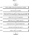
- FIG. 2 is a flowchart exemplarily showing a battery management method according to a first embodiment of the present disclosure
- FIG. 3 is a diagram showing an exemplary charging sequence table used to perform the battery management method of FIG. 2 .
- the battery management method of FIG. 2 is performed by the battery management system 300 to determine the remaining charging time that is the time required to charge the battery 200 from the current SOC to a target SOC.
- the control unit 330 detects a voltage, a current and a temperature of the battery 200 using the sensing unit 320. Specifically, when the sensing unit 320 outputs a voltage signal, a current signal and a temperature signal to the control unit 330, the control unit 330 generates battery information indicating the voltage, the current and the temperature of the battery 200 based on each signal.
- step S210 the control unit 330 determines the current SOC of the battery 200 based on each signal from the sensing unit 320.
- step S220 the control unit 330 determines a temperature range of interest, a SOC list of interest and a current list of interest from the charging sequence table DT based on the detected temperature.
- temperatures equal to or lower than -10°C are defined as the first temperature range
- temperatures between -10°C and 10°C are defined as the second temperature range
- temperatures equal to or higher than 10°C are defined as the third temperature range.
- the first SOC list defines 0 to 5% SOCs as the first SOC range, 5 to 10% SOCs as the second SOC range, 10 to 15% SOCs as the third SOC range, and 15 to 20% SOCs as the fourth SOC range, and 20 to 25% SOCs as the fifth SOC range.
- the second SOC list defines 0 to 10% SOCs as the first SOC range, 10 to 50% SOCs as the second SOC range, 50 to 80% SOCs as the third SOC range, and 80 to 90% SOCs as the fourth SOC range, and 90 to 95% SOCs as the fifth SOC range.
- the third SOC list defines 0 to 50% SOCs as the first SOC range, 50 to 80% SOCs as the second SOC range, 80 to 90% SOCs as the third SOC range, and 90 to 95% SOCs as the fourth SOC range, and 95 to 100% SOCs as the fifth SOC range.
- the first current list defines 4A (ampere) as the first allowable constant current, 3A as the second allowable constant current, 2A as the third allowable constant current, 1A as the fourth allowable constant current, and 0.3A as the fifth allowable constant current.
- the second current list defines 10A as the first allowable constant current, 8A as the second allowable constant current, 5A as the third allowable constant current, 2A as the fourth allowable constant current, and 1A as the fifth allowable constant current.
- the third current list defines 20A as the first allowable constant current, 10A as the second allowable constant current, 5.5A as the third allowable constant current, 2.3A as the fourth allowable constant current, and 1.1A as the fifth allowable constant current.
- the temperature range of interest is any one of the first to n th temperature ranges, to which the temperature detected in the step S200 belongs. For example, when the temperature detected in the step S200 is 0°C, since 0°C belongs to the second temperature range, the control unit 330 determines the second temperature range as the temperature range of interest. In addition, the control unit 330 may determine the second SOC list and the second current list associated with the temperature range of interest (-10°C to 10°C) as the SOC list of interest and the current list of interest respectively.
- the target SOC may be the upper limit of the n th SOC range defined by the SOC list of interest. For example, when the second current list is determined as the SOC list of interest, the control unit 330 may determine the target SOC to be equal to the upper limit (95%) of the fifth SOC range defined by the second current list.
- the control unit 330 determines first to n th set capacities.
- the first to n th set capacities correspond to the first to n th SOC ranges defined by the SOC list of interest in a one-to-one relationship.
- the j th set capacity is capacity corresponding to a difference between the lower limit and the upper limit of the j th SOC range defined by the SOC list of interest.
- the second set capacity may be equal to 40% of the maximum capacity.
- the upper limit of the j th SOC range may be equal to the lower limit of the j + 1 th SOC range.
- the second SOC list is the SOC list of interest, and the maximum capacity of the battery 200 is 10Ah (ampere-hour).
- the first set capacity is determined as 1Ah, the second set capacity as 4Ah, the third set capacity as 3Ah, the fourth set capacity as 1Ah, and the fifth set capacity as 0.5Ah.
- step S240 the control unit 330 determines first to n th target capacities.
- the first to n th target capacities also correspond to the first to n th SOC ranges defined by the SOC list of interest in a one-to-one relationship.
- the j th target capacity is the total capacity required to charge the battery 200 in the j th SOC range defined by the SOC list of interest.
- the second SOC list is the SOC list of interest
- the maximum capacity of the battery 200 is 10Ah
- the current SOC determined in the step S210 is 30%.
- the first target capacity is determined as 0Ah.
- the second target capacity is determined as 2Ah.
- the third to fifth target capacities are determined to be equal to the third to fifth set capacities respectively.
- step S250 the control unit 330 determines first to n th range estimated times.
- the first to n th range estimated times are based on the current detected in the step S200, the first to n th target capacities and the first to n th allowable constant currents defined by the current list of interest.
- the j th range estimated time is an estimated time required to charge the battery 200 in the j th SOC range.
- the control unit 330 may determine the first to n th range estimated times using the following Equation 1.
- ⁇ T r j ⁇ Q tg j MIN I m , I j
- I m denotes the current detected in the step S200
- I[j] denotes the j th allowable constant current of the current list of interest
- ⁇ Q tg [j] denotes the j th target capacity
- ⁇ T r [j] denotes the j th range estimated time.
- MIN(x, y) is a function that outputs a smaller one of x and y.
- MIN(z, z) z.
- step S260 the control unit 330 determines the remaining charging time.
- step S270 the control unit 330 outputs a notification message indicating the remaining charging time.
- the notification message may be transmitted to the charger 10 and/or a high-level controller 2 coupled to the control unit 330 via a wired or wireless communication channel.
- the high-level controller 2 may be an electronic control unit (ECU) of an electric vehicle 1.
- the communication channel may use, for example, the wired communication protocol such as Controller Area Network (CAN) or the wireless communication protocol such as ZigBee or Bluetooth.
- control unit 330 may control the charge of the battery 200 until the SOC of the battery 200 reaches the target SOC, according to the target charging sequence corresponding to each of the SOC list of interest and the current list of interest determined in the step S220.
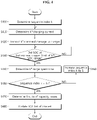
- FIG. 4 is a flowchart exemplarily showing a battery management method according to a second embodiment of the present disclosure
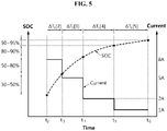
- FIG. 5 is a diagram for reference in describing an exemplary charging procedure by the battery management method of FIG. 4 .
- the battery management method of FIG. 4 is for charging the battery 200 according to the target charging sequence and updating the SOC list of interest used to determine the remaining charging time in the battery management method of FIG. 2 .
- the battery management method of FIG. 4 may be performed after the step S220.
- step S400 the control unit 330 determines a sequence index k based on the current SOC of the battery 200.
- step S410 the control unit 330 determines the k th charging current.
- step S420 the control unit 330 transmits to the charger 10 a k th command message requesting the supply of the k th charging current to the battery 200.
- the charger 10 is configured to supply the k th charging current to the battery 200 in response to the k th command message.
- step S430 the control unit 330 determines whether the SOC of the battery 200 reached the upper limit of the k th SOC range of the SOC list of interest. A value of the step S430 being "YES” indicates that the charging procedure in the k th SOC range has been completed. When the value of the step S430 is "YES”, step S440 is performed. When the value of the step S430 is "NO”, step S430 may be performed again.
- step S440 the control unit 330 determines the k th range spent time.
- the k th range spent time is the time spent in charging the battery 200 in the k th SOC range.
- the k th range spent time may be determined to be equal to the period of time from the time when the k th charging current was determined to the time when the SOC of the battery 200 reached the upper limit of the k th SOC range.
- step S450 the control unit 330 determines whether the sequence index k is equal to n. When a value of the step S450 is "NO”, step S460 is performed. The value of the step S450 being "YES” indicates that the SOC of the battery 200 reached the target SOC. When the value of the step S450 is "YES”, step S470 is performed.
- step S460 the control unit 330 increases the sequence index k by 1. After the step S460, the process may return to the step S410.
- step S470 the control unit 330 determines first to n th capacity losses.
- the j th capacity loss is a difference between the j th target capacity and the increased capacity of the battery 200 for the k th range spent time. That is, as the battery 200 degrades, the j th capacity loss may increase, and thus the j th capacity loss may indicate a decrease in the total capacity required to charge the j th SOC range.
- the control unit 330 may determine the first to n th capacity losses using the following Equation 2.
- ⁇ Q loss j ⁇ T r j ⁇ ⁇ T s j ⁇ MIN I m , I j
- Equation 2 may be expressed as the following Equation 2-1.
- ⁇ Q loss j ⁇ Q tg j ⁇ ⁇ T s j ⁇ MIN I m
- I j ⁇ Q tg j ⁇ ⁇ Q ch j
- Equation 2-1 ⁇ Q ch [j] denotes the increased capacity of the battery 200 for the k th range spent time.
- step S480 the control unit 330 updates the SOC list of interest.
- the control unit 330 may update the SOC list of interest recorded in the charging sequence table DT using the following Equation 3.
- Equation 3 ⁇ Q set [k] denotes the k th set capacity, Q max denotes the maximum capacity, SOC limit [j] denotes the upper limit of the j th SOC range defined by the updated SOC list of interest.
- the battery 200 is charged with the second charging current 8A.
- the time point t 3 is a time point when the SOC of the battery 200 reached the upper limit 50% of the second SOC range.
- the period of time ⁇ T s [2] from the time point t 2 from the time point t 3 is determined as the second range spent time spent in charging the second SOC range.
- the time point t 4 is a time point when the SOC of the battery 200 reached the upper limit 80% of the third SOC range.
- the period of time ⁇ T s [3] from the time point t 3 from the time point t 4 is determined as the third range spent time spent in charging in the third SOC range.
- the time point t 5 is a time point when the SOC of the battery 200 reached the upper limit 90% of the fourth SOC range.
- the period of time ⁇ T s [4] from the time point t 4 to the time point t 5 is determined as the fourth range spent time spent in charging in the four SOC range.
- the time point t 6 is a time point when the SOC of the battery 200 reached the target SOC 95% corresponding to the upper limit of the fifth SOC range.
- the period of time ⁇ T s [5] from the time point t 5 to the time point t 6 is determined as the fifth range spent time spent in charging in the fifth SOC range.
- constant current charging may be shifted to constant voltage charging.
- the first range spent time is 0 h.
- the first to fifth range estimated times are 0 h, 0.25 h, 0.375 h, 0.5 h, 0.5 h respectively
- the first to fifth range spent times are 0 h, 0.1875 h, 0.365 h, 0.375 h, 0.5 h respectively
- the maximum capacity Q max is 10 Ah.
- the first to fifth capacity losses are determined as 0 Ah, 0.5 Ah, 0.05 Ah, 0.25 Ah, 0 Ah respectively.
- the SOC list of interest is updated. That is, the upper limit of each of the first to fifth SOC ranges defined by the SOC list of interest is updated from 10%, 50%, 80%, 90%, 95% to 10%, 45%, 74.5%, 82%, 82.5%.
Landscapes
- Engineering & Computer Science (AREA)
- Power Engineering (AREA)
- General Chemical & Material Sciences (AREA)
- Manufacturing & Machinery (AREA)
- Chemical & Material Sciences (AREA)
- Chemical Kinetics & Catalysis (AREA)
- Electrochemistry (AREA)
- Mechanical Engineering (AREA)
- Transportation (AREA)
- General Physics & Mathematics (AREA)
- Physics & Mathematics (AREA)
- Sustainable Development (AREA)
- Sustainable Energy (AREA)
- Life Sciences & Earth Sciences (AREA)
- Microelectronics & Electronic Packaging (AREA)
- Secondary Cells (AREA)
- Charge And Discharge Circuits For Batteries Or The Like (AREA)
- Tests Of Electric Status Of Batteries (AREA)
- Electric Propulsion And Braking For Vehicles (AREA)
Claims (11)
- Batteriemanagementvorrichtung, umfassend:einen Speicher (310), welcher dazu eingerichtet ist, eine Ladesequenztabelle zu speichern, welche eine Korrespondenzbeziehung zwischen ersten bis mten Temperaturbereichen, ersten bis mten Ladezustand, SOC, -Listen und ersten bis mten Stromlisten aufzeichnet, wobei m eine natürliche Zahl von 2 oder größer ist;eine Erfassungseinheit (320), welche dazu eingerichtet ist, eine Spannung, einen Strom und eine Temperatur einer Batterie (200) zu detektieren; undeine Steuerungseinheit (330), welche betriebsmäßig mit dem Speicher und der Erfassungseinheit gekoppelt ist,wobei jede der SOC-Listen erste bis nte SOC-Bereiche definiert und n eine natürliche Zahl von 2 oder größer ist,jede der Stromlisten erste bis nte zulässige konstante Ströme definiert, welche den ersten bis nten SOC-Bereichen in einer Eins-zu-eins-Beziehung entsprechen, unddie Steuerungseinheit eingerichtet ist zum:Bestimmen eines aktuellen SOC der Batterie auf Grundlage der detektierten Spannung und des detektierten Stroms,Bestimmen eines Temperaturbereiches von Interesse, einer SOC-Liste von Interesse und einer Strom-Liste von Interesse aus der Ladesequenztabelle auf Grundlage der detektierten Temperatur, wobei der Temperaturbereich von Interesse ein Temperaturbereich unter den ersten ersten bis mten Temperaturbereichen ist, zu welchem die detektierte Temperatur gehört, wobei die SOC-Liste von Interesse eine SOC-Liste ist, welche unter den ersten bis mten SOC-Listen dem Temperaturbereich von Interesse entspricht, und die Stromliste von Interesse eine Stromliste ist, welche unter den ersten bis mten Stromlisten dem Temperaturbereich von Interesse entspricht, undBestimmen einer verbleibenden Ladezeit, welche erforderlich ist, um die Batterie bis zu einem Ziel-SOC zu laden, auf Grundlage des detektierten Stroms, des aktuellen SOC, der SOC-Liste von Interesse und der Stromliste von Interesse.
- Batteriemanagementvorrichtung nach Anspruch 1, wobei die Steuerungseinheit eingerichtet ist zum:Bestimmen erster bis nter festgelegter Kapazitäten, welche den ersten bis nten SOC-Bereichen, welche durch die SOC-Liste von Interesse definiert sind, in einer Eins-zu-eins-Beziehung entsprechen,Bestimmen erster bis nter Zielkapazitäten zum Laden der Batterie in jedem der ersten bis nten SOC-Bereiche, welche durch die SOC-Liste von Interesse definiert sind, auf Grundlage des aktuellen SOC und der ersten bis nten festgelegten Kapazitäten, undBestimmen der verbleibenden Ladezeit, auf Grundlage des detektierten Stroms, der ersten bis nten Zielkapazitäten und der ersten bis nten zulässigen konstanten Ströme, welche durch die Stromliste von Interesse definiert sind.
- Batteriemanagementvorrichtung nach Anspruch 2, wobei die Steuerungseinheit eingerichtet ist zum:Bestimmen erster bis nter geschätzter Bereichszeiten, welche erforderlich sind, um die Batterie in jedem der ersten bis nten SOC-Bereiche zu laden, unter Verwendung der folgenden Gleich 1:
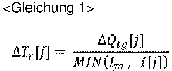 wobei in Gleichung 1, j eine natürliche Zahl von n oder kleiner bezeichnet, Im den detektierten Strom bezeichnet, I[j] den jten zulässigen konstanten Strom bezeichnet, MIN(Im, I[j]) ein kleineres von Im und I[j] bezeichnet, ΔQtg[j] die jte Zielkapazität bezeichnet, und ΔTr[j] die jte geschätzte Bereichszeit bezeichnet.
 - Batteriemanagementvorrichtung nach Anspruch 3, wobei die Steuerungseinheit dazu eingerichtet ist, die verbleibende Ladezeit derart zu bestimmen, dass sie gleich einer Summe der ersten bis nten geschätzten Bereichszeiten ist.
- Batteriemanagementvorrichtung nach Anspruch 3, wobei die Steuerungseinheit dazu eingerichtet ist, die ersten bis nten verbrachten Bereichszeiten, welche bei einem Laden in jedem aus den ersten bis nten SOC-Bereichen verbracht worden sind, während die Batterie zu dem Ziel-SOC geladen wird, gemäß einer Zielladesequenz zu bestimmen, welche der SOC-Liste von Interesse und der Stromliste von Interesse entspricht.
- Batteriemanagementvorrichtung nach Anspruch 5, wobei die Steuerungseinheit eingerichtet ist zum:Bestimmen erster bis nter Kapazitätsverluste, welche den ersten bis nten SOC-Bereichen in einer Eins-zu-eins-Beziehung entsprechen, auf Grundlage der ersten bis nten geschätzten Bereichszeiten und der ersten bis nten verbrachten Bereichszeiten, undAktualisieren der SOC-Liste von Interesse auf Grundlage der ersten bis nten Kapazitätsverluste.
- Batteriemanagementvorrichtung nach Anspruch 6, wobei die Steuerungseinheit dazu eingerichtet ist, die ersten bis nten Kapazitätsverluste unter Verwendung der folgenden Gleichung 2 zu bestimmen:

- Batteriemanagementvorrichtung nach Anspruch 7, wobei die Steuerungseinheit dazu eingerichtet ist, die SOC-Liste von Interesse unter Verwendung der folgenden Gleichung 3 zu aktualisieren:

- Batteriepack, umfassend die Batteriemanagementvorrichtung nach einem der Ansprüche 1 bis 8.
- Elektrofahrzeug, umfassend den Batteriepack nach Anspruch 9.
- Batteriemanagementverfahren, welches durch die Batteriemanagementvorrichtung nach einem der Ansprüche 1 bis 8 durchgeführt wird, wobei das Batteriemanagementverfahren umfasst:Speichern einer Ladesequenztabelle, welche eine Korrespondenzbeziehung zwischen ersten bis mten Temperaturbereichen, ersten bis mten Ladezustand, SOC, -Listen und ersten bis mten Stromlisten aufzeichnet, wobei m eine natürliche Zahl von 2 oder größer ist;Detektieren, durch die Erfassungseinheit (320), einer Spannung, eines Stroms und einer Temperatur der Batterie;wobei jede der SOC-Listen erste bis nte SOC-Bereiche definiert und n eine natürliche Zahl von 2 oder größer ist, und jede der Stromlisten erste bis nte zulässige konstante Ströme definiert, welche den ersten bis nten SOC-Bereichen in einer Eins-zu-eins-Beziehung entsprechen,Bestimmen, durch die Steuerungseinheit, eines aktuellen Ladezustands SOC der Batterie auf Grundlage der detektierten Spannung und des detektierten Stroms,Bestimmen, durch die Steuerungseinheit, des Temperaturbereiches von Interesse, der SOC-Liste von Interesse und der Strom-Liste von Interesse aus der Ladesequenztabelle auf Grundlage der detektierten Temperatur, wobei der Temperaturbereich von Interesse ein Temperaturbereich unter den ersten ersten bis mten Temperaturbereichen ist, zu welchem die detektierte Temperatur gehört, die SOC-Liste von Interesse eine SOC-Liste unter den ersten bis mten SOC-Listen ist, welche dem Temperaturbereich von Interesse entspricht, und die Stromliste von Interesse unter den ersten bis mten Stromlisten dem Temperaturbereich von Interesse entspricht, undBestimmen, durch die Steuerungseinheit, der verbleibenden Ladezeit, welche erforderlich ist, um die Batterie bis zu einem Ziel-SOC zu laden, auf Grundlage des detektierten Stroms, des aktuellen SOC, der SOC-Liste von Interesse und der Stromliste von Interesse.
Applications Claiming Priority (2)
| Application Number | Priority Date | Filing Date | Title |
|---|---|---|---|
| KR1020190110759A KR102743393B1 (ko) | 2019-09-06 | 2019-09-06 | 배터리 관리 장치, 배터리 관리 방법, 배터리 팩 및 전기 차량 |
| PCT/KR2020/009889 WO2021045387A1 (ko) | 2019-09-06 | 2020-07-27 | 배터리 관리 장치, 배터리 관리 방법, 배터리 팩 및 전기 차량 |
Publications (3)
| Publication Number | Publication Date |
|---|---|
| EP3923007A1 EP3923007A1 (de) | 2021-12-15 |
| EP3923007A4 EP3923007A4 (de) | 2022-04-13 |
| EP3923007B1 true EP3923007B1 (de) | 2022-10-12 |
Family
ID=74852524
Family Applications (1)
| Application Number | Title | Priority Date | Filing Date |
|---|---|---|---|
| EP20861336.4A Active EP3923007B1 (de) | 2019-09-06 | 2020-07-27 | Batterieverwaltungsvorrichtung, batterieverwaltungsverfahren, batteriepack und elektrofahrzeug |
Country Status (6)
| Country | Link |
|---|---|
| US (3) | US11912158B2 (de) |
| EP (1) | EP3923007B1 (de) |
| JP (1) | JP7188716B2 (de) |
| KR (1) | KR102743393B1 (de) |
| CN (1) | CN113784868B (de) |
| WO (1) | WO2021045387A1 (de) |
Families Citing this family (25)
| Publication number | Priority date | Publication date | Assignee | Title |
|---|---|---|---|---|
| KR102743393B1 (ko) * | 2019-09-06 | 2024-12-16 | 주식회사 엘지에너지솔루션 | 배터리 관리 장치, 배터리 관리 방법, 배터리 팩 및 전기 차량 |
| EP3859870A4 (de) * | 2019-10-21 | 2022-06-15 | Ningde Amperex Technology Ltd. | Elektronische vorrichtung und verfahren zum aufladen einer batterie |
| WO2021158724A1 (en) * | 2020-02-07 | 2021-08-12 | Enersys Delaware Inc. | Methods, systems, and devices for charging advanced sealed lead acid batteries |
| KR20210156618A (ko) * | 2020-06-18 | 2021-12-27 | 주식회사 엘지에너지솔루션 | 배터리 관리 시스템, 배터리 관리 방법, 배터리 팩 및 전기 차량 |
| US11603010B2 (en) * | 2020-09-23 | 2023-03-14 | Ford Global Technologies, Llc | Predicting charging time for battery of electrified vehicle |
| EP4086308B1 (de) | 2021-03-08 | 2025-08-20 | LG Chem, Ltd. | Thermoplastische harzzusammensetzung und aussenmaterial damit |
| EP4106078A4 (de) * | 2021-04-29 | 2023-01-11 | Contemporary Amperex Technology Co., Limited | Verfahren und vorrichtung zur einstellung der ladestrategie |
| KR102640846B1 (ko) | 2021-08-05 | 2024-02-27 | 삼성에스디아이 주식회사 | 배터리의 충전 소요 시간을 추정하는 방법 및 장치 |
| JP7773342B2 (ja) * | 2021-11-05 | 2025-11-19 | Fdk株式会社 | バッテリバンクユニット、充電残時間算出方法、および、充電残時間算出プログラム |
| CN114475353B (zh) * | 2022-01-20 | 2023-11-10 | 上海汽车集团股份有限公司 | 动力电池充电时间预估方法、装置、电子设备及存储介质 |
| CN114407727A (zh) * | 2022-01-24 | 2022-04-29 | 四川野马汽车股份有限公司 | 一种电动汽车充电剩余时间的估算方法及系统 |
| CN117183823B (zh) * | 2022-05-30 | 2024-10-29 | 比亚迪股份有限公司 | 充电控制方法、充电控制装置及车辆 |
| KR20240006308A (ko) * | 2022-07-06 | 2024-01-15 | 주식회사 엘지에너지솔루션 | 웨이크업 회로 및 이를 포함하는 배터리 시스템 |
| CN115047352A (zh) * | 2022-07-19 | 2022-09-13 | 北京汽车研究总院有限公司 | 电池剩余充电时间计算方法、装置及车辆 |
| CN115459380A (zh) * | 2022-08-30 | 2022-12-09 | 重庆长安新能源汽车科技有限公司 | 蓄电池的补电方法、装置、车辆及存储介质 |
| JP7790683B2 (ja) * | 2022-09-15 | 2025-12-23 | エルジー エナジー ソリューション リミテッド | バッテリー管理システム、バッテリーパック、電気車両及びバッテリー充電時間の予測方法 |
| JP2025501111A (ja) * | 2022-09-15 | 2025-01-17 | エルジー エナジー ソリューション リミテッド | バッテリー管理システム、バッテリーパック、電気車両及びバッテリー充電時間の予測方法 |
| JP2024064485A (ja) * | 2022-10-28 | 2024-05-14 | 日立建機株式会社 | 電動式作業機械 |
| CN115972977B (zh) * | 2023-03-10 | 2023-05-23 | 北京集度科技有限公司 | 对动力电池进行充电的控制装置、方法、车辆和存储介质 |
| WO2025028149A1 (ja) * | 2023-07-28 | 2025-02-06 | パナソニックIpマネジメント株式会社 | 電池管理装置、電池パック、電池管理方法および電池管理プログラム |
| CN117301954B (zh) * | 2023-09-26 | 2024-07-16 | 重庆赛力斯新能源汽车设计院有限公司 | 电池荷电状态的调整方法、装置、电子设备及存储介质 |
| US20250105649A1 (en) * | 2023-09-27 | 2025-03-27 | Iontra Inc | Method and system for optimal charging process of lithium-ion batteries to mitigate cell degradation in real time |
| KR102763534B1 (ko) * | 2024-02-19 | 2025-02-07 | 주식회사 크로커스 | 스마트 출력 및 디스펜서 확장가능한 전기차 충전 시스템 |
| CN118169585B (zh) * | 2024-05-14 | 2024-07-30 | 东方旭能(山东)科技发展有限公司 | 一种基于安时积分法的锂电池soc估计方法 |
| KR20260024899A (ko) * | 2024-08-14 | 2026-02-23 | 주식회사 엘지에너지솔루션 | 전자 장치 및 그의 배터리 성능 평가 방법 |
Family Cites Families (30)
| Publication number | Priority date | Publication date | Assignee | Title |
|---|---|---|---|---|
| JP2743155B2 (ja) | 1995-06-16 | 1998-04-22 | 株式会社ジップチャージ | 充電装置及び充電処理システム |
| JPH10172616A (ja) | 1996-12-17 | 1998-06-26 | Sanyo Electric Co Ltd | 充電装置 |
| US7323848B2 (en) * | 2002-12-11 | 2008-01-29 | Japan Storage Battery Co., Ltd. | Battery charging state arithmetic operation device for calculating charging state of battery, and battery charging state arithmetic operation method |
| JP4215013B2 (ja) | 2005-03-16 | 2009-01-28 | セイコーエプソン株式会社 | 充電残り時間算出装置 |
| JP4624272B2 (ja) * | 2006-02-03 | 2011-02-02 | 本田技研工業株式会社 | 燃料電池車両の制御方法および燃料電池車両 |
| WO2008026477A1 (en) | 2006-08-29 | 2008-03-06 | Nec Corporation | Method and device for estimating soc value of secondary battery and degradation judging method and device |
| TWI316609B (en) * | 2006-12-26 | 2009-11-01 | Shun Hsing Wang | A method of calculating remaining capacity of rechargeable battery |
| JP4805863B2 (ja) | 2007-03-07 | 2011-11-02 | 長野日本無線株式会社 | 充電装置 |
| US7928735B2 (en) * | 2007-07-23 | 2011-04-19 | Yung-Sheng Huang | Battery performance monitor |
| US8624560B2 (en) * | 2008-04-11 | 2014-01-07 | Apple Inc. | Controlling battery charging based on current, voltage and temperature |
| JP5098912B2 (ja) * | 2008-07-11 | 2012-12-12 | ソニー株式会社 | バッテリパックおよび充電制御システム |
| JP4744622B2 (ja) | 2009-07-01 | 2011-08-10 | トヨタ自動車株式会社 | 車両の制御装置 |
| US8405356B2 (en) | 2010-03-05 | 2013-03-26 | Panasonic Corporation | Full charge capacity value correction circuit, battery pack, and charging system |
| US8706333B2 (en) * | 2011-06-28 | 2014-04-22 | Ford Global Technologies, Llc | Nonlinear observer for battery state of charge estimation |
| US9746525B2 (en) * | 2011-09-08 | 2017-08-29 | Hitachi Automotive Systems, Ltd. | Battery system monitoring device |
| JP2013115862A (ja) | 2011-11-25 | 2013-06-10 | Sharp Corp | 充電装置、電気機器、および、クーロンカウンタ |
| KR101660194B1 (ko) | 2012-09-21 | 2016-09-26 | 닛산 지도우샤 가부시키가이샤 | 충전 제어 장치 및 충전 시간 연산 방법 |
| JP6068100B2 (ja) | 2012-11-09 | 2017-01-25 | 日本電気株式会社 | 電池制御装置、蓄電装置、蓄電方法、及びプログラム |
| US9337680B2 (en) | 2013-03-12 | 2016-05-10 | Ford Global Technologies, Llc | Method and system for controlling an electric vehicle while charging |
| KR101480616B1 (ko) | 2013-06-05 | 2015-01-09 | 현대자동차주식회사 | 전기자동차용 탑재형 배터리 충전장치 및 이의 제어방법 |
| CA2839758A1 (en) * | 2014-01-20 | 2015-07-20 | Thomson Power, Inc. | Electric vehicle generator opportunity charging control system |
| US9381825B2 (en) * | 2014-02-20 | 2016-07-05 | Ford Global Technologies, Llc | State of charge quality based cell balancing control |
| KR101936465B1 (ko) | 2016-09-21 | 2019-01-08 | 현대자동차주식회사 | 배터리 충전 시스템 및 방법 |
| KR102695516B1 (ko) | 2016-11-18 | 2024-08-14 | 삼성전자주식회사 | 배터리 충전 방법, 배터리 충전 정보 생성 방법 및 배터리 충전 장치 |
| KR101948252B1 (ko) | 2017-03-24 | 2019-02-14 | 현대자동차주식회사 | 전기 자동차 및 전기 자동차의 배터리 충전 방법 |
| KR102554151B1 (ko) | 2017-10-24 | 2023-07-12 | 삼성전자주식회사 | 배터리 충전 방법 및 장치 |
| KR102507816B1 (ko) * | 2017-12-18 | 2023-03-08 | 현대자동차주식회사 | 배터리 충전 방법 및 시스템 |
| KR102363032B1 (ko) | 2018-03-21 | 2022-02-16 | 주식회사 엘지화학 | 전이금속 복합체의 제조 방법 |
| WO2019230131A1 (ja) * | 2018-05-31 | 2019-12-05 | 本田技研工業株式会社 | 充電制御装置、輸送機器、及びプログラム |
| KR102743393B1 (ko) * | 2019-09-06 | 2024-12-16 | 주식회사 엘지에너지솔루션 | 배터리 관리 장치, 배터리 관리 방법, 배터리 팩 및 전기 차량 |
-
2019
- 2019-09-06 KR KR1020190110759A patent/KR102743393B1/ko active Active
-
2020
- 2020-07-27 CN CN202080031449.8A patent/CN113784868B/zh active Active
- 2020-07-27 EP EP20861336.4A patent/EP3923007B1/de active Active
- 2020-07-27 WO PCT/KR2020/009889 patent/WO2021045387A1/ko not_active Ceased
- 2020-07-27 JP JP2021538098A patent/JP7188716B2/ja active Active
- 2020-07-27 US US17/420,867 patent/US11912158B2/en active Active
-
2024
- 2024-02-23 US US18/586,325 patent/US12370922B2/en active Active
-
2025
- 2025-07-11 US US19/267,271 patent/US20250340151A1/en active Pending
Also Published As
| Publication number | Publication date |
|---|---|
| KR20210029878A (ko) | 2021-03-17 |
| US20250340151A1 (en) | 2025-11-06 |
| WO2021045387A1 (ko) | 2021-03-11 |
| US11912158B2 (en) | 2024-02-27 |
| US20210370796A1 (en) | 2021-12-02 |
| JP2022516264A (ja) | 2022-02-25 |
| KR102743393B1 (ko) | 2024-12-16 |
| CN113784868B (zh) | 2023-08-04 |
| EP3923007A4 (de) | 2022-04-13 |
| EP3923007A1 (de) | 2021-12-15 |
| US12370922B2 (en) | 2025-07-29 |
| US20240300378A1 (en) | 2024-09-12 |
| JP7188716B2 (ja) | 2022-12-13 |
| CN113784868A (zh) | 2021-12-10 |
Similar Documents
| Publication | Publication Date | Title |
|---|---|---|
| EP3923007B1 (de) | Batterieverwaltungsvorrichtung, batterieverwaltungsverfahren, batteriepack und elektrofahrzeug | |
| EP3982141B1 (de) | Batterieverwaltungseinrichtung, batterieverwaltungsverfahren, batteriepack und elektrofahrzeug | |
| US10873201B2 (en) | Battery management apparatus and method for protecting a lithium iron phosphate cell from over-voltage using the same | |
| EP3444888B1 (de) | Vorrichtung und verfahren zur batterieverwaltung | |
| US10340714B2 (en) | System for controlling output parameter of secondary battery, and method therefor | |
| US9142980B2 (en) | Apparatus and method for controlling charge capacity balancing operation of secondary battery cell | |
| KR102784717B1 (ko) | 배터리 관리 시스템, 배터리 관리 방법, 배터리 팩 및 전기 차량 | |
| KR102758018B1 (ko) | 배터리 관리 시스템, 배터리 팩, 에너지 저장 시스템 및 배터리 관리 방법 | |
| US20220176845A1 (en) | Battery management system, battery pack, electric vehicle, and battery management method | |
| EP4725752A2 (de) | Batterieverwaltungssystem, batterieverwaltungsverfahren, batteriepack und elektrofahrzeug | |
| US20250070281A1 (en) | Battery Management System, Battery Pack, Electric Vehicle and Battery Charging Time Prediction Method | |
| US12040647B2 (en) | Battery management system, battery pack, electric vehicle, and battery management method | |
| EP3633782B1 (de) | Batterieverwaltungssystem und -verfahren zur optimierung des inneren widerstands einer batterie | |
| EP4152472A1 (de) | Batterieverwaltungssystem, batterieverwaltungsverfahren, batteriepack und elektrofahrzeug | |
| EP4068562A1 (de) | Batterieverwaltungsvorrichtung, batterieverwaltungsverfahren, batteriepack und elektrofahrzeug | |
| US12344120B2 (en) | Battery management system, battery management method, battery pack, and electric vehicle | |
| CN107359377B (zh) | 电池包充电方法、装置和设备 | |
| EP4697552A1 (de) | Batterieverwaltungsvorrichtung und batterieausgleichsverfahren damit |
Legal Events
| Date | Code | Title | Description |
|---|---|---|---|
| STAA | Information on the status of an ep patent application or granted ep patent |
Free format text: STATUS: THE INTERNATIONAL PUBLICATION HAS BEEN MADE |
|
| PUAI | Public reference made under article 153(3) epc to a published international application that has entered the european phase |
Free format text: ORIGINAL CODE: 0009012 |
|
| STAA | Information on the status of an ep patent application or granted ep patent |
Free format text: STATUS: REQUEST FOR EXAMINATION WAS MADE |
|
| 17P | Request for examination filed |
Effective date: 20210910 |
|
| AK | Designated contracting states |
Kind code of ref document: A1 Designated state(s): AL AT BE BG CH CY CZ DE DK EE ES FI FR GB GR HR HU IE IS IT LI LT LU LV MC MK MT NL NO PL PT RO RS SE SI SK SM TR |
|
| RAP3 | Party data changed (applicant data changed or rights of an application transferred) |
Owner name: LG ENERGY SOLUTION, LTD. |
|
| A4 | Supplementary search report drawn up and despatched |
Effective date: 20220316 |
|
| RIC1 | Information provided on ipc code assigned before grant |
Ipc: B60L 3/00 20190101ALI20220310BHEP Ipc: B60L 58/12 20190101ALI20220310BHEP Ipc: H01M 10/48 20060101ALI20220310BHEP Ipc: H01M 10/42 20060101ALI20220310BHEP Ipc: G01R 31/36 20200101ALI20220310BHEP Ipc: G01R 31/387 20190101AFI20220310BHEP |
|
| REG | Reference to a national code |
Ref country code: DE Ref legal event code: R079 Ref document number: 602020005642 Country of ref document: DE Free format text: PREVIOUS MAIN CLASS: G01R0031387000 Ipc: H02J0007000000 |
|
| RIC1 | Information provided on ipc code assigned before grant |
Ipc: H01M 10/42 20060101ALI20220428BHEP Ipc: H01M 10/48 20060101ALI20220428BHEP Ipc: B60L 58/12 20190101ALI20220428BHEP Ipc: B60L 3/00 20190101ALI20220428BHEP Ipc: G01R 31/36 20200101ALI20220428BHEP Ipc: H02J 7/00 20060101AFI20220428BHEP |
|
| GRAP | Despatch of communication of intention to grant a patent |
Free format text: ORIGINAL CODE: EPIDOSNIGR1 |
|
| STAA | Information on the status of an ep patent application or granted ep patent |
Free format text: STATUS: GRANT OF PATENT IS INTENDED |
|
| INTG | Intention to grant announced |
Effective date: 20220603 |
|
| GRAS | Grant fee paid |
Free format text: ORIGINAL CODE: EPIDOSNIGR3 |
|
| GRAA | (expected) grant |
Free format text: ORIGINAL CODE: 0009210 |
|
| STAA | Information on the status of an ep patent application or granted ep patent |
Free format text: STATUS: THE PATENT HAS BEEN GRANTED |
|
| AK | Designated contracting states |
Kind code of ref document: B1 Designated state(s): AL AT BE BG CH CY CZ DE DK EE ES FI FR GB GR HR HU IE IS IT LI LT LU LV MC MK MT NL NO PL PT RO RS SE SI SK SM TR |
|
| DAV | Request for validation of the european patent (deleted) | ||
| DAX | Request for extension of the european patent (deleted) | ||
| REG | Reference to a national code |
Ref country code: GB Ref legal event code: FG4D |
|
| REG | Reference to a national code |
Ref country code: CH Ref legal event code: EP |
|
| REG | Reference to a national code |
Ref country code: DE Ref legal event code: R096 Ref document number: 602020005642 Country of ref document: DE |
|
| REG | Reference to a national code |
Ref country code: IE Ref legal event code: FG4D |
|
| REG | Reference to a national code |
Ref country code: AT Ref legal event code: REF Ref document number: 1524752 Country of ref document: AT Kind code of ref document: T Effective date: 20221115 |
|
| REG | Reference to a national code |
Ref country code: LT Ref legal event code: MG9D |
|
| REG | Reference to a national code |
Ref country code: NL Ref legal event code: MP Effective date: 20221012 |
|
| REG | Reference to a national code |
Ref country code: AT Ref legal event code: MK05 Ref document number: 1524752 Country of ref document: AT Kind code of ref document: T Effective date: 20221012 |
|
| PG25 | Lapsed in a contracting state [announced via postgrant information from national office to epo] |
Ref country code: NL Free format text: LAPSE BECAUSE OF FAILURE TO SUBMIT A TRANSLATION OF THE DESCRIPTION OR TO PAY THE FEE WITHIN THE PRESCRIBED TIME-LIMIT Effective date: 20221012 |
|
| PG25 | Lapsed in a contracting state [announced via postgrant information from national office to epo] |
Ref country code: SE Free format text: LAPSE BECAUSE OF FAILURE TO SUBMIT A TRANSLATION OF THE DESCRIPTION OR TO PAY THE FEE WITHIN THE PRESCRIBED TIME-LIMIT Effective date: 20221012 Ref country code: PT Free format text: LAPSE BECAUSE OF FAILURE TO SUBMIT A TRANSLATION OF THE DESCRIPTION OR TO PAY THE FEE WITHIN THE PRESCRIBED TIME-LIMIT Effective date: 20230213 Ref country code: NO Free format text: LAPSE BECAUSE OF FAILURE TO SUBMIT A TRANSLATION OF THE DESCRIPTION OR TO PAY THE FEE WITHIN THE PRESCRIBED TIME-LIMIT Effective date: 20230112 Ref country code: LT Free format text: LAPSE BECAUSE OF FAILURE TO SUBMIT A TRANSLATION OF THE DESCRIPTION OR TO PAY THE FEE WITHIN THE PRESCRIBED TIME-LIMIT Effective date: 20221012 Ref country code: FI Free format text: LAPSE BECAUSE OF FAILURE TO SUBMIT A TRANSLATION OF THE DESCRIPTION OR TO PAY THE FEE WITHIN THE PRESCRIBED TIME-LIMIT Effective date: 20221012 Ref country code: ES Free format text: LAPSE BECAUSE OF FAILURE TO SUBMIT A TRANSLATION OF THE DESCRIPTION OR TO PAY THE FEE WITHIN THE PRESCRIBED TIME-LIMIT Effective date: 20221012 Ref country code: AT Free format text: LAPSE BECAUSE OF FAILURE TO SUBMIT A TRANSLATION OF THE DESCRIPTION OR TO PAY THE FEE WITHIN THE PRESCRIBED TIME-LIMIT Effective date: 20221012 |
|
| PG25 | Lapsed in a contracting state [announced via postgrant information from national office to epo] |
Ref country code: RS Free format text: LAPSE BECAUSE OF FAILURE TO SUBMIT A TRANSLATION OF THE DESCRIPTION OR TO PAY THE FEE WITHIN THE PRESCRIBED TIME-LIMIT Effective date: 20221012 Ref country code: PL Free format text: LAPSE BECAUSE OF FAILURE TO SUBMIT A TRANSLATION OF THE DESCRIPTION OR TO PAY THE FEE WITHIN THE PRESCRIBED TIME-LIMIT Effective date: 20221012 Ref country code: LV Free format text: LAPSE BECAUSE OF FAILURE TO SUBMIT A TRANSLATION OF THE DESCRIPTION OR TO PAY THE FEE WITHIN THE PRESCRIBED TIME-LIMIT Effective date: 20221012 Ref country code: IS Free format text: LAPSE BECAUSE OF FAILURE TO SUBMIT A TRANSLATION OF THE DESCRIPTION OR TO PAY THE FEE WITHIN THE PRESCRIBED TIME-LIMIT Effective date: 20230212 Ref country code: HR Free format text: LAPSE BECAUSE OF FAILURE TO SUBMIT A TRANSLATION OF THE DESCRIPTION OR TO PAY THE FEE WITHIN THE PRESCRIBED TIME-LIMIT Effective date: 20221012 Ref country code: GR Free format text: LAPSE BECAUSE OF FAILURE TO SUBMIT A TRANSLATION OF THE DESCRIPTION OR TO PAY THE FEE WITHIN THE PRESCRIBED TIME-LIMIT Effective date: 20230113 |
|
| P01 | Opt-out of the competence of the unified patent court (upc) registered |
Effective date: 20230512 |
|
| REG | Reference to a national code |
Ref country code: DE Ref legal event code: R097 Ref document number: 602020005642 Country of ref document: DE |
|
| PG25 | Lapsed in a contracting state [announced via postgrant information from national office to epo] |
Ref country code: SM Free format text: LAPSE BECAUSE OF FAILURE TO SUBMIT A TRANSLATION OF THE DESCRIPTION OR TO PAY THE FEE WITHIN THE PRESCRIBED TIME-LIMIT Effective date: 20221012 Ref country code: RO Free format text: LAPSE BECAUSE OF FAILURE TO SUBMIT A TRANSLATION OF THE DESCRIPTION OR TO PAY THE FEE WITHIN THE PRESCRIBED TIME-LIMIT Effective date: 20221012 Ref country code: EE Free format text: LAPSE BECAUSE OF FAILURE TO SUBMIT A TRANSLATION OF THE DESCRIPTION OR TO PAY THE FEE WITHIN THE PRESCRIBED TIME-LIMIT Effective date: 20221012 Ref country code: DK Free format text: LAPSE BECAUSE OF FAILURE TO SUBMIT A TRANSLATION OF THE DESCRIPTION OR TO PAY THE FEE WITHIN THE PRESCRIBED TIME-LIMIT Effective date: 20221012 Ref country code: CZ Free format text: LAPSE BECAUSE OF FAILURE TO SUBMIT A TRANSLATION OF THE DESCRIPTION OR TO PAY THE FEE WITHIN THE PRESCRIBED TIME-LIMIT Effective date: 20221012 |
|
| PLBE | No opposition filed within time limit |
Free format text: ORIGINAL CODE: 0009261 |
|
| STAA | Information on the status of an ep patent application or granted ep patent |
Free format text: STATUS: NO OPPOSITION FILED WITHIN TIME LIMIT |
|
| PG25 | Lapsed in a contracting state [announced via postgrant information from national office to epo] |
Ref country code: SK Free format text: LAPSE BECAUSE OF FAILURE TO SUBMIT A TRANSLATION OF THE DESCRIPTION OR TO PAY THE FEE WITHIN THE PRESCRIBED TIME-LIMIT Effective date: 20221012 Ref country code: AL Free format text: LAPSE BECAUSE OF FAILURE TO SUBMIT A TRANSLATION OF THE DESCRIPTION OR TO PAY THE FEE WITHIN THE PRESCRIBED TIME-LIMIT Effective date: 20221012 |
|
| 26N | No opposition filed |
Effective date: 20230713 |
|
| PG25 | Lapsed in a contracting state [announced via postgrant information from national office to epo] |
Ref country code: SI Free format text: LAPSE BECAUSE OF FAILURE TO SUBMIT A TRANSLATION OF THE DESCRIPTION OR TO PAY THE FEE WITHIN THE PRESCRIBED TIME-LIMIT Effective date: 20221012 |
|
| PG25 | Lapsed in a contracting state [announced via postgrant information from national office to epo] |
Ref country code: MC Free format text: LAPSE BECAUSE OF FAILURE TO SUBMIT A TRANSLATION OF THE DESCRIPTION OR TO PAY THE FEE WITHIN THE PRESCRIBED TIME-LIMIT Effective date: 20221012 |
|
| PG25 | Lapsed in a contracting state [announced via postgrant information from national office to epo] |
Ref country code: MC Free format text: LAPSE BECAUSE OF FAILURE TO SUBMIT A TRANSLATION OF THE DESCRIPTION OR TO PAY THE FEE WITHIN THE PRESCRIBED TIME-LIMIT Effective date: 20221012 |
|
| REG | Reference to a national code |
Ref country code: CH Ref legal event code: PL |
|
| REG | Reference to a national code |
Ref country code: BE Ref legal event code: MM Effective date: 20230731 |
|
| PG25 | Lapsed in a contracting state [announced via postgrant information from national office to epo] |
Ref country code: LU Free format text: LAPSE BECAUSE OF NON-PAYMENT OF DUE FEES Effective date: 20230727 |
|
| PG25 | Lapsed in a contracting state [announced via postgrant information from national office to epo] |
Ref country code: LU Free format text: LAPSE BECAUSE OF NON-PAYMENT OF DUE FEES Effective date: 20230727 |
|
| REG | Reference to a national code |
Ref country code: IE Ref legal event code: MM4A |
|
| PG25 | Lapsed in a contracting state [announced via postgrant information from national office to epo] |
Ref country code: CH Free format text: LAPSE BECAUSE OF NON-PAYMENT OF DUE FEES Effective date: 20230731 |
|
| PG25 | Lapsed in a contracting state [announced via postgrant information from national office to epo] |
Ref country code: IT Free format text: LAPSE BECAUSE OF FAILURE TO SUBMIT A TRANSLATION OF THE DESCRIPTION OR TO PAY THE FEE WITHIN THE PRESCRIBED TIME-LIMIT Effective date: 20221012 Ref country code: BE Free format text: LAPSE BECAUSE OF NON-PAYMENT OF DUE FEES Effective date: 20230731 |
|
| PG25 | Lapsed in a contracting state [announced via postgrant information from national office to epo] |
Ref country code: IE Free format text: LAPSE BECAUSE OF NON-PAYMENT OF DUE FEES Effective date: 20230727 |
|
| PG25 | Lapsed in a contracting state [announced via postgrant information from national office to epo] |
Ref country code: IE Free format text: LAPSE BECAUSE OF NON-PAYMENT OF DUE FEES Effective date: 20230727 |
|
| PG25 | Lapsed in a contracting state [announced via postgrant information from national office to epo] |
Ref country code: BG Free format text: LAPSE BECAUSE OF FAILURE TO SUBMIT A TRANSLATION OF THE DESCRIPTION OR TO PAY THE FEE WITHIN THE PRESCRIBED TIME-LIMIT Effective date: 20221012 |
|
| PG25 | Lapsed in a contracting state [announced via postgrant information from national office to epo] |
Ref country code: BG Free format text: LAPSE BECAUSE OF FAILURE TO SUBMIT A TRANSLATION OF THE DESCRIPTION OR TO PAY THE FEE WITHIN THE PRESCRIBED TIME-LIMIT Effective date: 20221012 |
|
| PGFP | Annual fee paid to national office [announced via postgrant information from national office to epo] |
Ref country code: GB Payment date: 20250624 Year of fee payment: 6 |
|
| PGFP | Annual fee paid to national office [announced via postgrant information from national office to epo] |
Ref country code: FR Payment date: 20250624 Year of fee payment: 6 |
|
| PG25 | Lapsed in a contracting state [announced via postgrant information from national office to epo] |
Ref country code: CY Free format text: LAPSE BECAUSE OF FAILURE TO SUBMIT A TRANSLATION OF THE DESCRIPTION OR TO PAY THE FEE WITHIN THE PRESCRIBED TIME-LIMIT; INVALID AB INITIO Effective date: 20200727 |
|
| PG25 | Lapsed in a contracting state [announced via postgrant information from national office to epo] |
Ref country code: HU Free format text: LAPSE BECAUSE OF FAILURE TO SUBMIT A TRANSLATION OF THE DESCRIPTION OR TO PAY THE FEE WITHIN THE PRESCRIBED TIME-LIMIT; INVALID AB INITIO Effective date: 20200727 |
|
| PGFP | Annual fee paid to national office [announced via postgrant information from national office to epo] |
Ref country code: DE Payment date: 20250624 Year of fee payment: 6 |
|
| PG25 | Lapsed in a contracting state [announced via postgrant information from national office to epo] |
Ref country code: TR Free format text: LAPSE BECAUSE OF FAILURE TO SUBMIT A TRANSLATION OF THE DESCRIPTION OR TO PAY THE FEE WITHIN THE PRESCRIBED TIME-LIMIT Effective date: 20221012 |