EP3923052A1 - Kernader für glasfaserband vom intermittierenden verbindungstyp, glasfaserkabel und verfahren zur herstellung einer kernader für glasfaserband vom intermittierenden verbindungstyp - Google Patents
Kernader für glasfaserband vom intermittierenden verbindungstyp, glasfaserkabel und verfahren zur herstellung einer kernader für glasfaserband vom intermittierenden verbindungstyp Download PDFInfo
- Publication number
- EP3923052A1 EP3923052A1 EP20752474.5A EP20752474A EP3923052A1 EP 3923052 A1 EP3923052 A1 EP 3923052A1 EP 20752474 A EP20752474 A EP 20752474A EP 3923052 A1 EP3923052 A1 EP 3923052A1
- Authority
- EP
- European Patent Office
- Prior art keywords
- optical fiber
- coupling
- resin
- optical fibers
- fiber ribbon
- Prior art date
- Legal status (The legal status is an assumption and is not a legal conclusion. Google has not performed a legal analysis and makes no representation as to the accuracy of the status listed.)
- Granted
Links
Images


Classifications
-
- G—PHYSICS
- G02—OPTICS
- G02B—OPTICAL ELEMENTS, SYSTEMS OR APPARATUS
- G02B6/00—Light guides; Structural details of arrangements comprising light guides and other optical elements, e.g. couplings
- G02B6/44—Mechanical structures for providing tensile strength and external protection for fibres, e.g. optical transmission cables
- G02B6/4479—Manufacturing methods of optical cables
- G02B6/448—Ribbon cables
-
- G—PHYSICS
- G02—OPTICS
- G02B—OPTICAL ELEMENTS, SYSTEMS OR APPARATUS
- G02B6/00—Light guides; Structural details of arrangements comprising light guides and other optical elements, e.g. couplings
- G02B6/44—Mechanical structures for providing tensile strength and external protection for fibres, e.g. optical transmission cables
- G02B6/4401—Optical cables
- G02B6/4403—Optical cables with ribbon structure
Definitions
- the present disclosure relates to an intermittently coupled-type optical fiber ribbon, an optical fiber cable, and a method for manufacturing an intermittently coupled-type optical fiber ribbon.
- Patent Literature 1 describes an optical fiber ribbon which is not an intermittently coupled-type.
- the optical fiber ribbon a plurality of optical fibers are arranged in parallel and are integrated by a sheath over the entire outer circumference of the arranged optical fibers and over the entire length of the optical fibers.
- Patent Literature 2 describes an intermittently coupled-type optical fiber ribbon in which a coupling resin is intermittently filled in the circumferential direction of optical fibers.
- Patent Literature 3 describes an intermittently coupled-type optical fiber ribbon in which a coupling portion is broken in a state where a colored layer adheres to the coupling portion to be separated into single optical fibers.
- Patent Literature 4 describes an intermittently coupled-type optical fiber ribbon in which a distance between centers of adjacent optical fibers is set to 250 ⁇ 30 ⁇ m by using small-diameter optical fibers having an outer diameter of 220 ⁇ m or less.
- an intermittently coupled-type optical fiber ribbon in which, in a state where a plurality of optical fibers are arranged in parallel, coupling portions at which adj acent optical fibers are coupled by a coupling resin and non-coupling portions at which the adjacent optical fibers are not coupled are intermittently provided in a longitudinal direction, the coupling portions and the non-coupling portions being provided between some or all of the plurality of optical fibers, in which at least some of the non-coupling portions include a convex portion of the coupling resin, a tip end of the convex portion having an acute angle in a cross-sectional view in a direction orthogonal to the longitudinal direction.
- an optical fiber cable in which the intermittently coupled-type optical fiber ribbon described above is installed, in which a fiber density of the optical fiber cable obtained by dividing the number of optical fibers by a cable cross-sectional area is 4.5 fibers/mm 2 or more.
- an intermittently coupled-type optical fiber ribbon in which, in a state where a plurality of optical fibers are arranged in parallel, coupling portions at which adjacent optical fibers are coupled by a coupling resin and non-coupling portions at which the adjacent optical fibers are not coupled are intermittently provided in a longitudinal direction, the coupling portions and the non-coupling portions being provided between some or all of the plurality of optical fibers, the method including:
- Patent Literature 4 describes an intermittently coupled-type optical fiber ribbon using small-diameter optical fibers having an outer diameter of 220 ⁇ m or less.
- the optical fibers have a small diameter, a coating layer is thin and the lateral pressure resistance is weak.
- the transmission loss may increase when adjacent intermittently coupled-type optical fiber ribbons come into close contact and lateral pressure is applied to the intermittently coupled-type optical fiber ribbons, for example, when the intermittently coupled-type optical fiber ribbons are accommodated in an optical fiber cable.
- An object of the present disclosure is to provide an intermittently coupled-type optical fiber ribbon, an optical fiber cable, and a method for manufacturing an intermittently coupled-type optical fiber ribbon, in which the intermittently coupled-type optical fiber ribbon can be easily separated into single optical fibers.
- an intermittently coupled-type optical fiber ribbon an optical fiber cable, and a method for manufacturing an intermittently coupled-type optical fiber ribbon, in which the intermittently coupled-type optical fiber ribbon can be easily separated into single optical fibers.
- an optical fiber cable in which the intermittently coupled-type optical fiber ribbon according to any one of (1) to (7) is installed, in which a fiber density of the optical fiber cable obtained by dividing the number of optical fibers by a cable cross-sectional area is 4.5 fibers/mm 2 or more.
- the optical fiber cable has a fiber density of 4.5 fibers/mm 2 or more, the optical fibers can be installed at a high density. Even the optical fiber cable in which intermittently coupled-type optical fiber ribbons are accommodated at a high density can be easily separated into single optical fibers.
- an intermittently coupled-type optical fiber ribbon in which, in a state where a plurality of optical fibers are arranged in parallel, coupling portions at which adjacent optical fibers are coupled by a coupling resin and non-coupling portions at which the adjacent optical fibers are not coupled are intermittently provided in a longitudinal direction, the coupling portions and the non-coupling portions being provided between some or all of the plurality of optical fibers, the method including:
- the tip end of the broken surface where the coupling resin is broken becomes a convex portion having an acute angle in a cross-sectional view in a direction orthogonal to the longitudinal direction.
- the coupling resin can be easily peeled off from the intermittently coupled-type optical fiber ribbon.
- the coupling resin is peeled off in this way, the intermittently coupled-type optical fiber ribbon is separated into single optical fibers. Therefore, it is possible to manufacture an intermittently coupled-type optical fiber ribbon that can be easily separated into single optical fibers without cutting or removing the coupling resin of the coupling portion with a tool or the like.
- FIG. 1 is a plan view showing an example of the intermittently coupled-type optical fiber ribbon according to the embodiment.
- FIG. 1 shows an intermittently coupled-type optical fiber ribbon 1 (hereinafter, referred to as the optical fiber ribbon 1) in a state where non-coupling portions 13 are expanded in the arrangement direction of optical fibers 11A to 11L.
- the optical fiber ribbon 1 includes a plurality of optical fibers 11 arranged in parallel.
- twelve optical fibers 11A to 11L are arranged in parallel.
- the twelve optical fibers 11A to 11L are coupled by a coupling resin in such a way that at least a part of an optical fiber is in contact with at least a part of an adjacent optical fiber.
- the optical fiber ribbon 1 is an intermittently coupled-type optical fiber ribbon including, at every other two optical fibers, coupling portions 12 at which optical fibers are coupled by a coupling resin and the non-coupling portions 13 at which the optical fibers are not coupled by a coupling resin.
- the coupling portions 12 and the non-coupling portions 13 are intermittently provided in the longitudinal direction of the optical fibers.
- the coupling portions 12 and the non-coupling portions 13 are provided between the optical fibers 11B, 11C, between the optical fibers 11D, 11E, between the optical fibers 11F, 11G, between the optical fibers 11H, 111, and between the optical fibers 11J, 11K.
- This example shows an intermittently coupled-type optical fiber ribbon including twelve optical fibers, but the number of optical fibers is not limited to twelve.
- the number of optical fibers may be twelve or more as long as the number is a multiple of four.
- the number of optical fibers may be 16, 20, 24, ..., and 96.
- FIG. 2 is a cross-sectional view of the optical fiber ribbon 1 in FIG. 1 taken from a line A-A in a case where a coupling resin 18 is coated on only one surface of the optical fiber ribbon 1.
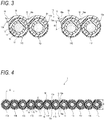
- FIG. 3 is an enlarged view of the vicinity of the non-coupling portions 13 of the optical fiber ribbon 1 of FIG. 2 , and shows a state in which the non-coupling portions 13 (space between the optical fibers) are closed.
- each of the optical fibers 11 includes, for example, a glass fiber 14 including a core and a cladding, two coating layers 15, 16 covering the circumference of the glass fiber 14, and a colored layer 17 covering the circumference of the coating layers 15, 16.
- the inner coating layer 15 of the two coating layers is formed of a primary resin.
- the outer coating layer 16 of the two coating layers is formed of a secondary resin.
- a soft resin having a relatively small Young's modulus is used as a buffer layer.
- a hard resin having a relatively large Young's modulus is used as a protective layer.
- the secondary resin has a Young's modulus of 900 MPa or more, preferably 1000 MPa or more, and more preferably 1500 MPa or more at 23°C.
- the secondary resin constituting the outer coating layer 16 is a resin composition containing a base resin and hydrophobic inorganic oxide particles.
- the base resin contains a urethane acrylate oligomer or a urethane methacrylate oligomer, a monomer having a phenoxy group, a photopolymerization initiator, and a silane coupling agent.
- the content of the inorganic oxide particles in the resin composition is 1% by mass or more and 45% by mass or less based on the total amount of the resin composition.
- (meth)acrylate acrylate or methacrylate corresponding to acrylate is referred to as (meth)acrylate.
- urethane (meth)acrylate oligomer an oligomer obtained by reacting a polyol compound, a polyisocyanate compound, and a hydroxyl group-containing (meth)acrylate compound can be used.
- the oligomer is obtained by, for example, reacting polypropylene glycol having a molecular weight of 4,000, isophorone diisocyanate, hydroxyethyl acrylate, and methanol.
- a phenoxy group-containing (meth)acrylate compound can be used as the monomer having a phenoxy group.
- An example of the monomer having a phenoxy group includes nonylphenol EO-modified acrylate (trade name "Aronix M-113" manufactured by Toagosei Co., Ltd.).
- the photopolymerization initiator can be appropriately selected and used from known radical photopolymerization initiators.
- the photopolymerization initiator is 2,4,6-trimethylbenzoyldiphenylphosphine oxide.
- the silane coupling agent is not particularly limited as long as it does not hinder the curing of the resin composition.
- An example of the silane coupling agent includes 3-mercaptopropyltrimethoxysilane.
- the hydrophobic inorganic oxide particles are obtained by introducing a hydrophobic group into surfaces of the inorganic oxide particles.
- the inorganic oxide particles are, for example, silica particles.
- the hydrophobic group may be a reactive group such as a (meth)acryloyl group or a vinyl group, or a non-reactive group such as a hydrocarbon group (for example, an alkyl group) or an aryl group (for example, a phenyl group).
- the primary resin constituting the inner coating layer 15 and the secondary resin constituting the outer coating layer 16 are formed of, for example, an ultraviolet curable resin and a thermosetting resin.
- the optical fibers 11 have a bending loss of 0.25 dB/10 turns or less when the bending radius R is 15 mm.
- the coupling resin 18 that couples adjacent optical fiber cores 11A to 11L is coated on only one side (upper side in FIGs. 2 and 3 ) of the optical fibers 11A to 11L arranged in parallel when viewed from a direction perpendicular to the parallel direction (vertical direction in FIGs. 2 and 3 ).
- the coupling resin 18 is coated in a shape including concave portions 18a between optical fibers corresponding to recesses between adjacent optical fibers.
- the coupling portions 12 and the non-coupling portions 13 are intermittently provided in the longitudinal direction every other two optical fibers as described above.
- the coupling portions 12 and the non-coupling portions 13 are intermittently coupled by the coupling resin 18.
- an ultraviolet curable resin and a thermosetting resin can be used for the coupling resin 18.
- the non-coupling portions 13 of the optical fiber ribbon 1 are formed with broken surfaces 13a penetrating upper and lower surfaces of the optical fiber ribbon 1 relative to the coupling resin 18.
- Such broken surfaces 13a are formed by the breakage of the coupling resin 18 provided between the optical fibers.
- FIG. 3 shows the enlarged optical fibers 11C to 11F in a state where the non-coupling portion 13 between the optical fibers 11D, 11E is expanded in the arrangement direction.
- the broken surfaces 13a at the non-coupling portion 13 are obtained by the coupling resin 18 being broken in an oblique direction (from the upper left to the lower right in FIG. 3 ).
- Positions where the broken surfaces 13a are formed in the coupling resin 18 are positions deviated from central positions of the concave portions 18a in the alignment direction of the optical fibers.
- the coating thickness B1 is smaller than the coating thickness B2. That is, the broken surfaces 13a start from a part where the coating thickness of the coupling resin 18 is small.
- the coating thickness of the coupling resin 18 is large (coating thickness B2) in the central positions of the concave portions 18a, and is substantially the same (coating thickness B1) in the rest of the parts.
- the coupling resin 18 at the non-coupling portions 13 where the broken surfaces 13a are formed is broken from a part where the thickness of the coupling resin 18 is small, tip end portions of the broken surfaces 13a are formed into convex portions 19 having an acute angle in a cross-sectional view in the direction orthogonal to the longitudinal direction of the optical fiber ribbon 1.
- the colored layer 17 is exposed at least at a part of the optical fibers 11 at the non-coupling portions 13.
- the coupling resin 18 has a Young's modulus of 1200 MPa or less, and preferably 500 MPa or less at room temperature (for example, 23°C).
- the breaking elongation of the coupling resin 18 is 150% or less at room temperature (for example, 23°C).
- the optical fibers 11A to 11L having the above configuration have an outer diameter C (see FIG. 2 ) of 220 ⁇ m or less.
- a distance D between centers of adjacent optical fibers in the optical fibers 11A to 11L is 230 ⁇ m or less.
- the optical fiber ribbon 1 has a thickness E of 230 ⁇ m or less when the coupling resin 18 is coated on surfaces on only one side of the optical fibers.
- the minimum coating thickness of the coupling resin 18 is the coating thickness B1 (see FIG. 3 ), and the thickness is 10 ⁇ m or less.
- the optical fiber ribbon 1 is configured in such a way that the optical fibers 11A to 11L are arranged in parallel in a state of being in contact with each other and surfaces on only one side of the optical fibers 11 are coated with the coupling resin 18, the present disclosure is not limited thereto.
- the optical fibers 11A to 11L may be coupled by coating surfaces on both sides of the optical fibers 11A to 11L arranged in parallel with the coupling resin 18.
- FIG. 4 is a cross-sectional view of the optical fiber ribbon 1 in FIG. 1 taken along the line A-A in a case where the coupling resin 18 is coated on both surfaces of the optical fiber ribbon 1, and shows a state in which the non-coupling portions 13 (space between the optical fibers) are closed.
- FIG. 5 is an enlarged view of the vicinity of the non-coupling portions 13 of the optical fiber ribbon 1 of FIG. 4 .
- the coupling resin 18 is coated on both surfaces of the optical fiber ribbon 1, the convex portions 19 are formed on both the surfaces, and the thickness E of the optical fiber ribbon 1 is 240 ⁇ m or less.
- the optical fibers 11A to 11L may be arranged in parallel in a state where a slight gap exists between adjacent optical fibers, and the optical fibers 11A to 11L may be coated and coupled in a state where the coupling resin 18 enters the gap between the optical fibers.
- FIG. 6 shows another example of the intermittently coupled-type optical fiber ribbon according to the present embodiment.
- an intermittently coupled-type optical fiber ribbon 2 (hereinafter, referred to as the optical fiber ribbon 2) of this example is different from the optical fiber ribbon 1 of FIG. 1 , in which the coupling portions 12 and the non-coupling portions 13 are provided every other two optical fibers, in that coupling portions 22 and non-coupling portions 23 are provided between all optical fibers.
- the non-coupling portions 23 are formed with break surfaces 23a corresponding to the broken surfaces 13a of the non-coupling portions 13 in the optical fiber ribbon 1 of FIG. 1 .
- the optical fiber ribbon 2 includes twelve optical fibers 21 (21A to 21L in this example), and the number of optical fibers is the same as that of the optical fiber ribbon 1 in FIG. 1 .
- Other configurations for example, glass fibers and coating layers forming the optical fibers, the coating thickness B of the coupling resin, the outer diameter C of the optical fibers, the distance D between centers of the optical fibers, the thickness E of the optical fiber ribbon, and the bending loss of the optical fibers are the same as those of the optical fiber ribbon 1 of FIG. 1 .
- the surface on which the coupling resin 18 is coated may be one surface or both surfaces.
- the coupling resin 18 When viewed from a direction perpendicular to the direction in which the optical fibers are arranged in parallel, the coupling resin 18 is coated on one side of the optical fibers 11A to 11L arranged in parallel in a state where at least a part of an optical fiber is in contact with at least a part of an adjacent optical fiber.
- the coupling resin 18 is coated to form the concave portions 18a between the optical fibers so that the cross section between the optical fibers has a recessed shape.
- the coupling portions 12 that couple adjacent optical fibers are formed.
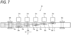
- FIG. 7 shows an example of a non-coupling portion forming device 30 that forms the non-coupling portions 13 in the optical fiber ribbon 1.
- the optical fiber ribbon 1 coated with the coupling resin 18 is caused to run on the non-coupling portion forming device 30.
- the optical fiber ribbon 1 runs from right to left (in the direction of an arrow F) through a pass line of the non-coupling portion forming device 30. Since the optical fiber ribbon 1 includes twelve optical fibers 11A to 11L and the non-coupling portions 13 are formed every other two optical fibers, five breaking mechanisms 31a to 31e are prepared.
- the non-coupling portions 23 are formed in the optical fiber ribbon 2 of FIG. 6 , the non-coupling portions 23 are formed for each optical fiber, and thus eleven breaking mechanisms are prepared.
- the breaking mechanisms 31a to 31e stagger, for example, between guide rollers 32a, 32b that guide the running of the optical fiber ribbon 1 in the pass line direction of the non-coupling portion forming device 30 (the longitudinal direction of the optical fiber ribbon 1).
- the breaking mechanisms 31a to 31e respectively include pressing members 33a to 33e having sharp tip ends.
- the pressing members 33a to 33e are abutted against the concave portions 18a of the coupling resin 18 between predetermined optical fibers of the optical fibers 11A to 11L from the side of the optical fiber ribbon 1 on which the coupling resin 18 is coated and apply a pressing force to the concave portions 18a.
- a force acts to pull the coupling resin 18 toward locations against which the tip ends of the pressing members 33a to 33e abut. Due to this pulling force, the coupling resin 18 is broken to be torn off starting from a part where the coating thickness of the coupling resin is smaller than the coating thickness of the coupling resin at the concave portions 18a (for example, a part of the coating thickness B1 shown in FIG. 3 ). As a result, as shown in FIG. 3 , the tip ends of the broken surfaces 13a of the coupling resin 18 become the convex portions 19 having an acute angle in a cross-sectional view in a direction orthogonal to the longitudinal direction of the optical fiber ribbon 1.
- the "pressing members having sharp tip ends” have, for example, a certain degree of a small area in contact with the coupling resin 18 and can apply a pressing force to the coupling resin 18, and thus may be members that can break the coupling resin 18 as described above.
- cutter blades, thin plate-shaped members, and needle-shaped members can be used as the pressing members 33a to 33e.
- the coupling resin 18 between the optical fibers 11 is intermittently broken in the longitudinal direction of the optical fibers 11, and parts where the broken surfaces 13a are formed are the non-coupling portions 13 as shown in FIGs. 1 and 3 .
- the intermittently coupled-type optical fiber ribbon 1 is manufactured, and the manufactured optical fiber ribbon 1 is wound by a winding bobbin.
- the optical fiber ribbon 2 can be manufactured by the same manufacturing method as that of the optical fiber ribbon 1 by changing the number of breaking mechanisms or the like.
- the above-described intermittently coupled-type optical fiber ribbon 1 (2) has the convex portions 19 of the coupling resin 18 in the non-coupling portions 13 (23) of the intermittent structure.
- the convex portions 19 include tip ends having an acute angle in the cross-sectional view in the direction orthogonal to the longitudinal direction. For this reason, when the convex portions 19 are pinched and pulled by, for example, a finger, the coupling resin 18 can be easily peeled off from the optical fiber ribbon 1 (2). When the coupling resin 18 is peeled off in this way, the optical fiber ribbon 1 (2) is separated into every two (single) optical fibers 11 (21). Therefore, in the intermittently coupled-type optical fiber ribbon 1 (2), the optical fibers 11 can be easily separated into single optical fibers without cutting or removing the coupling resin 18 of the coupling portions 12 (22) with a tool or the like.
- the optical fiber ribbon 1 (2) when the optical fiber ribbon 1 (2) is aligned again after being intermittently broken, the convex portions 19 and the concave portions of the coupling resin 18 in the non-coupling portions 13 (23) are combined and the non-coupling portions 13 (23) have substantially the same shape as the coupling portions 12 (22). For this reason, the optical fiber ribbon 1 (2) can be aligned in the width direction without unevenness due to steps. As a result, when the optical fiber ribbons 1 (2) are collectively fusion-spliced, the alignability of the optical fiber ribbons 1 (2) in the width direction can be improved, the fusion-splicing workability is good, and a splicing error can be less likely to occur.
- the optical fibers 11 can be easily separated into single optical fibers even when the small-diameter optical fibers 11 having an outer diameter of 220 ⁇ m or less are used.
- the coupling resin 18 can be easily peeled off since the non-coupling portions 13 (23) have a part where the colored layer 17 is exposed.
- the coupling resin 18 in the non-coupling portions 13 has the convex portions 19, for example, in a case where the optical fiber ribbons 1 (2) are gathered to be rounded and accommodated in an optical fiber cable, the convex portions 19 are pressed against the optical fibers 11 and transmission loss due to microbend may increase.
- the optical fiber ribbon 1 (2) is soft when the Young's modulus of the coupling resin 18 at room temperature is 1200 MPa or less. Accordingly, an increase in the transmission loss can be prevented even when the convex portions 19 are pressed.
- the breaking elongation of the coupling resin 18 When the breaking elongation of the coupling resin 18 is large, it is difficult to break the coupling resin 18. However, in the optical fiber ribbon 1 (2), the breaking elongation of the coupling resin 18 at normal temperature is 150% or less. Accordingly, it is easy to break the coupling resin 18 to form the non-coupling portions 13 at the time of manufacturing and the intermittent workability is good.
- the coating thickness in the concave portions 18a in the coupling resin 18 is different from the coating thickness in the rest of the parts, and the coupling resin 18 has locations where the coating thickness is small.
- the minimum coating thickness of the coupling resin 18 is 10 ⁇ m or less. Accordingly, it is easy to break the coupling resin 18 at the time of manufacturing.
- the lateral pressure resistance of the optical fibers 11 can be enhanced by using a resin containing the inorganic oxide particles as the secondary resin of the coating layer 16 of the optical fibers 11. Therefore, when the optical fiber ribbon 1 (2) is constituted by such optical fibers 11, an increase in the transmission loss when the optical fiber ribbons 1 (2) are accommodated in an optical fiber cable can be prevented, and thus the optical fiber ribbons 1 (2) can be accommodated in the optical fiber cable at a high density.
- the tip ends of the broken surfaces 13a where the coupling resin 18 is broken are the convex portions 19 having an acute angle in the cross-sectional view in the direction orthogonal to the longitudinal direction. Therefore, according to the method for manufacturing an optical fiber ribbon according to the present embodiment, as described above, it is possible to manufacture the optical fiber ribbon 1 (2) in which the coupling resin 18 can be easily peeled off.
- the optical fiber ribbon 1 (2) manufactured by the above manufacturing method has good fusion workability and splicing errors are less likely to occur.
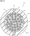
- FIG. 8 shows an example of a slotless optical fiber cable using the optical fiber ribbon 1 (2) according to the present embodiment.
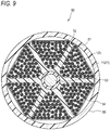
- FIG. 9 shows an example of a slot optical fiber cable using the optical fiber ribbon 1 (2) according to the present embodiment.
- a slotless optical fiber cable 40 shown in FIG. 8 includes a cylindrical tube 41 and a plurality of optical fiber ribbons 1 (2) installed in the tube 41.
- the optical fiber ribbons 1 (2) are gathered to be rounded and are stranded.
- a plurality of fillers (tensile fibers and the like) 42 are accommodated in the tube 41 to fill gaps between the optical fiber ribbons 1 (2).
- the circumference of the tube 41 is covered with a sheath 44 together with a tension member 43.
- a tear string 45 is provided inside the sheath 44.
- the optical fibers 11 (21) have a fiber density of 4.5 fibers/mm 2 or more per unit area in the cable cross section.
- the fiber density is calculated by dividing the number of the optical fibers by the cross-sectional area of the optical fiber cable.
- the slotless optical fiber cable 40 shown in FIG. 8 has 432 fibers.
- the optical fibers 11 (21) can be installed in the optical fiber cable 40 at a fiber density of 4.55 fibers/mm 2 .
- a slot optical fiber cable 50 shown in FIG. 9 includes a slotted rod 52 having a plurality of slot grooves 51, and a plurality of optical fiber ribbons 1 (2) accommodated in the slot grooves 51.
- the slotted rod 52 has a tension member 53 at the center, and the plurality of slot grooves 51 are radially provided.
- the optical fiber ribbons 1 (2) are gathered to be rounded, stranded, and accommodated in the slot grooves 51.
- a wrapping tape 54 is wrapped around the slotted rod 52, and a sheath 55 is formed on the circumference of the wrapping tape 54.
- the fiber density is 4.5 core/mm 2 or more.
- the slot optical fiber cable 50 shown in FIG. 9 has 3456 fibers.
- the optical fibers 11 (21) can be accommodated in the optical fiber cable 50 at a fiber density of 5.62 fibers/mm 2 .
- the optical fiber cables 40, 50 contain the optical fiber ribbons 1 (2) having the above-described configuration. Therefore, even in a case where the optical fiber ribbons 1 (2) are accommodated at a large fiber density of 4.5 fibers/mm 2 or more, the single optical fibers 11 (21) can be easily separated without cutting or removing the coupling resin 18 of the coupling portions 12 with a tool or the like when the optical fiber ribbons 1 (2) are taken out from the optical fiber cables 40, 50.
- samples No. 1 to 9 are intermittently coupled-type optical fiber ribbons including twelve optical fibers.
- an intermittent pattern is formed every other two optical fibers.
- the intermittent pattern is the same as that of the optical fiber ribbon 1.
- the Young's modulus and the breaking elongation of the coupling resin are values at room temperature (23°C).
- the intermittent workability was determined by whether the tip ends of the coupling resin 18 in the non-coupling portions 13 could be broken to form the acute convex portions 19 as shown in FIG. 3 when the non-coupling portions 13 were formed in the optical fiber ribbon 1 using the non-coupling portion forming device 30 shown in FIG. 7 .
- a sample whose coupling resin 18 could be broken as the non-coupling portions 13 in FIG. 3 was determined to have good intermittent workability and evaluated as A.
- a sample whose coupling resin 18 could not be broken in some cases was determined to have intermittent workability inferior to that of Evaluation A and evaluated as B. That is, the sample of Evaluation A includes a coupling resin having good intermittent workability.
- the cable loss characteristics were determined based on whether the bending loss satisfies 0.3 dB/km or less at the wavelength of signal light of 1.55 ⁇ m when optical fiber ribbons including coupling resins of the above samples were installed in the optical fiber cable 40 shown in FIG. 8 .
- An optical fiber ribbon having a bending loss of 0.3 dB/km or less was determined to have good cable loss characteristics and evaluated as A.
- An optical fiber ribbon having a bending loss of more than 0.3 dB/km was determined to have poor cable loss characteristics and evaluated as B. That is, the sample of Evaluation A includes a coupling resin having good cable loss characteristics.
- the Young's modulus of the coupling resin affects the cable loss characteristics.
- the Young's modulus of the coupling resin is increased, for example, when the optical fiber ribbons 1 are gathered to be rounded and accommodated in the optical fiber cable 40, the convex portions 19 of the coupling resin 18 are pressed against the optical fibers 11, and the loss characteristics are deteriorated due to microbending.
- the breaking elongation of the coupling resin affects the intermittent workability.
- the breaking elongation of the coupling resin is increased, the coupling resin 18 is stretched even when a pressing force is applied from the pressing members 33a to 33e, and thus the coupling resin 18 cannot be broken well.
- samples having good intermittent workability were No. 3 and No. 5 to 9.
- the optical fiber ribbons 1 have good intermittent workability when the breaking elongation of the coupling resin is 150% or less.
- Samples having good cable loss characteristics were No. 1 to 8. As a result, it was found that the optical fiber ribbons 1 have good cable loss characteristics when the Young's modulus of the coupling resin is 1200 MPa or less.
Landscapes
- Physics & Mathematics (AREA)
- General Physics & Mathematics (AREA)
- Optics & Photonics (AREA)
- Engineering & Computer Science (AREA)
- Manufacturing & Machinery (AREA)
- Mechanical Coupling Of Light Guides (AREA)
- Optical Fibers, Optical Fiber Cores, And Optical Fiber Bundles (AREA)
Applications Claiming Priority (2)
| Application Number | Priority Date | Filing Date | Title |
|---|---|---|---|
| JP2019019603 | 2019-02-06 | ||
| PCT/JP2020/004373 WO2020162501A1 (ja) | 2019-02-06 | 2020-02-05 | 間欠連結型光ファイバテープ心線、光ファイバケーブルおよび間欠連結型光ファイバテープ心線の製造方法 |
Publications (3)
| Publication Number | Publication Date |
|---|---|
| EP3923052A1 true EP3923052A1 (de) | 2021-12-15 |
| EP3923052A4 EP3923052A4 (de) | 2022-03-16 |
| EP3923052B1 EP3923052B1 (de) | 2026-02-25 |
Family
ID=71947511
Family Applications (1)
| Application Number | Title | Priority Date | Filing Date |
|---|---|---|---|
| EP20752474.5A Active EP3923052B1 (de) | 2019-02-06 | 2020-02-05 | Ein intermittierend gekoppeltes optisches faserband und ein verfahren zu seiner herstellung |
Country Status (5)
| Country | Link |
|---|---|
| US (1) | US11415769B2 (de) |
| EP (1) | EP3923052B1 (de) |
| JP (1) | JP7447818B2 (de) |
| CN (1) | CN113316733B (de) |
| WO (1) | WO2020162501A1 (de) |
Cited By (1)
| Publication number | Priority date | Publication date | Assignee | Title |
|---|---|---|---|---|
| EP4266100A4 (de) * | 2020-12-18 | 2024-05-15 | Sumitomo Electric Industries, Ltd. | Optisches faserband |
Families Citing this family (4)
| Publication number | Priority date | Publication date | Assignee | Title |
|---|---|---|---|---|
| EP4692882A3 (de) * | 2020-08-31 | 2026-05-06 | Corning Research & Development Corporation | Intermittierend gebondetes band mit intermittierenden bindungen, die mit einem nass-in-nass-verfahren hergestellt werden |
| WO2022093664A1 (en) * | 2020-10-29 | 2022-05-05 | Corning Research & Development Corporation | Intermittently bonded optical fiber ribbon with joining ribbon matrices |
| CN113946025B (zh) * | 2021-12-20 | 2022-03-22 | 长飞光纤光缆股份有限公司 | 一种柔性光纤带、高密度光缆及固化树脂应用 |
| EP4524630A4 (de) * | 2022-05-11 | 2025-09-10 | Sumitomo Electric Industries | Optisches faserband |
Family Cites Families (28)
| Publication number | Priority date | Publication date | Assignee | Title |
|---|---|---|---|---|
| JP2706285B2 (ja) | 1988-12-23 | 1998-01-28 | 関西ペイント株式会社 | 活性エネルギー線硬化型組成物 |
| JPH09218328A (ja) * | 1997-01-09 | 1997-08-19 | Fujikura Ltd | 分割型光ファイバテープ |
| JP2001116967A (ja) * | 1999-08-06 | 2001-04-27 | Shin Etsu Chem Co Ltd | 光ファイバテープ及びその製造方法 |
| US7151879B2 (en) | 2002-11-06 | 2006-12-19 | Sumitomo Electric Industries, Ltd. | Optical fiber ribbon that is easily branched into individual optical fibers and optical fiber cable using the same |
| JP3664254B2 (ja) | 2002-11-06 | 2005-06-22 | 住友電気工業株式会社 | 光ファイバテープ心線及びその製造方法 |
| JP4249634B2 (ja) * | 2004-01-30 | 2009-04-02 | 三菱化学株式会社 | 放射線硬化性樹脂組成物及び放射線硬化性樹脂組成物の製造方法 |
| WO2006049296A1 (ja) | 2004-11-08 | 2006-05-11 | Mitsubishi Chemical Corporation | 放射線硬化性組成物及びその硬化物、並びにその積層体 |
| JP2006188659A (ja) * | 2004-12-07 | 2006-07-20 | Mitsubishi Chemicals Corp | 放射線硬化性樹脂組成物およびその硬化物 |
| JP2007131698A (ja) * | 2005-10-11 | 2007-05-31 | Mitsubishi Chemicals Corp | 放射線硬化性組成物及びその硬化物、並びにその積層体 |
| JP2011158581A (ja) * | 2010-01-29 | 2011-08-18 | Jsr Corp | 光ファイバテープ層形成用液状硬化性樹脂組成物および光ファイバテープ心線 |
| JP5445240B2 (ja) * | 2010-03-10 | 2014-03-19 | 住友電気工業株式会社 | 光ファイバケーブルおよびその製造方法 |
| JP2011232733A (ja) * | 2010-04-07 | 2011-11-17 | Sumitomo Electric Ind Ltd | 光ファイバテープ心線、光ファイバケーブル、及び光ファイバテープ心線の製造方法 |
| JP5200093B2 (ja) * | 2010-11-18 | 2013-05-15 | 株式会社フジクラ | 光ファイバテープ心線の製造方法、製造装置、及びその製造方法で製造された光ファイバテープ心線並びに光ファイバケーブル |
| JP5779940B2 (ja) * | 2011-03-30 | 2015-09-16 | 住友電気工業株式会社 | 光ファイバテープ心線の製造装置および製造方法 |
| JP5564026B2 (ja) | 2011-10-18 | 2014-07-30 | 株式会社フジクラ | 光ファイバテープ心線及びその光ファイバテープ心線を収納した光ファイバケーブル |
| WO2014054129A1 (ja) * | 2012-10-03 | 2014-04-10 | 住友電気工業株式会社 | 光ファイバテープ心線 |
| JP2014117800A (ja) | 2012-12-13 | 2014-06-30 | Yokohama Rubber Co Ltd:The | 空気入りタイヤの加硫異常検知方法および装置 |
| JP5852045B2 (ja) * | 2013-05-07 | 2016-02-03 | 株式会社フジクラ | 光ファイバテープ心線及び光ファイバケーブル |
| JP2015108756A (ja) * | 2013-12-05 | 2015-06-11 | 住友電気工業株式会社 | 光ファイバユニット、光ファイバケーブルおよび光ファイバユニットの製造方法 |
| DE102014223935A1 (de) | 2014-11-25 | 2016-05-25 | Henkel Ag & Co. Kgaa | Mittel zum Färben von keratinischen Fasern, enthaltend mindestens einen dimeren, dikationischen Azofarbstoff und mindestens ein anionisches und/oder kationisches Tensid |
| JP2017026754A (ja) * | 2015-07-21 | 2017-02-02 | 昭和電線ケーブルシステム株式会社 | 光ファイバテープ心線および光ファイバケーブル |
| MX393960B (es) | 2015-07-31 | 2025-03-19 | Corning Optical Communications LLC | Cinta de fibra optica enrollable. |
| JP6569429B2 (ja) | 2015-09-25 | 2019-09-04 | 住友電気工業株式会社 | 光ファイバテープ心線 |
| JP6657976B2 (ja) * | 2016-01-13 | 2020-03-04 | 住友電気工業株式会社 | 間欠連結型光ファイバテープ心線および光ケーブル |
| EP3422062B1 (de) * | 2016-02-23 | 2025-09-03 | Sumitomo Electric Industries, Ltd. | Glasfaserband mit unterbrochener verbindung, herstellungsverfahren für glasfaserband mit unterbrochener verbindung, glasfaserband und glasfaserkabel |
| JP6781113B2 (ja) | 2017-07-20 | 2020-11-04 | ミサワホーム株式会社 | ドア装置 |
| JP2019049617A (ja) * | 2017-09-08 | 2019-03-28 | 住友電気工業株式会社 | 光ファイバテープ心線および光ファイバテープ心線の製造方法 |
| AU2018401778C1 (en) | 2018-01-15 | 2024-08-08 | Prysmian S.P.A. | A method for producing a flexible optical fiber ribbon and said ribbon. |
-
2020
- 2020-02-05 US US17/428,893 patent/US11415769B2/en active Active
- 2020-02-05 CN CN202080009864.3A patent/CN113316733B/zh active Active
- 2020-02-05 JP JP2020571236A patent/JP7447818B2/ja active Active
- 2020-02-05 EP EP20752474.5A patent/EP3923052B1/de active Active
- 2020-02-05 WO PCT/JP2020/004373 patent/WO2020162501A1/ja not_active Ceased
Cited By (2)
| Publication number | Priority date | Publication date | Assignee | Title |
|---|---|---|---|---|
| EP4266100A4 (de) * | 2020-12-18 | 2024-05-15 | Sumitomo Electric Industries, Ltd. | Optisches faserband |
| US12321027B2 (en) | 2020-12-18 | 2025-06-03 | Sumitomo Electric Industries, Ltd. | Optical fiber ribbon |
Also Published As
| Publication number | Publication date |
|---|---|
| EP3923052A4 (de) | 2022-03-16 |
| EP3923052B1 (de) | 2026-02-25 |
| CN113316733A (zh) | 2021-08-27 |
| US11415769B2 (en) | 2022-08-16 |
| JP7447818B2 (ja) | 2024-03-12 |
| US20220075134A1 (en) | 2022-03-10 |
| JPWO2020162501A1 (ja) | 2021-12-09 |
| CN113316733B (zh) | 2023-07-18 |
| WO2020162501A1 (ja) | 2020-08-13 |
Similar Documents
| Publication | Publication Date | Title |
|---|---|---|
| US11415769B2 (en) | Intermittent connection-type optical fiber tape core wire, optical fiber cable, and method for manufacturing intermittent connection-type optical fiber tape core wire | |
| JP4049154B2 (ja) | 光ファイバテープ心線 | |
| CN100365458C (zh) | 具有优先撕裂部分的可剥离缓冲层及其制造方法 | |
| CN101443684B (zh) | 光纤分配缆线及其结构 | |
| US8600205B2 (en) | Optical fiber array cables and associated fiber optic cables and systems | |
| CN100399090C (zh) | 具有优先拉扯部分的光纤带 | |
| EP3978976B1 (de) | Kernader für glasfaserband, glasfaserkabel und verfahren von herstellung einer kernader für glasfaserband | |
| JP3664254B2 (ja) | 光ファイバテープ心線及びその製造方法 | |
| JP3902201B2 (ja) | 光ファイバ素線及び光ファイバテープ心線 | |
| US20230393350A1 (en) | Optical fiber ribbon and method for manufacturing optical fiber ribbon | |
| EP3943992A1 (de) | Glasfaserbandkern mit intermittierender verbindung, glasfaserkabel und mit verbinder versehener glasfaserkord | |
| JP7816160B2 (ja) | 光ファイバテープ心線 | |
| CN101872044B (zh) | 光纤分配缆线及其结构 | |
| KR20130106818A (ko) | 플라스틱 광파이버 유닛 및 그것을 사용한 플라스틱 광파이버 케이블 | |
| JP2020204687A (ja) | 光ファイバテープ心線、光ファイバケーブルおよび光ファイバテープ心線の製造方法 | |
| EP4667432A1 (de) | Verfahren zur herstellung einer optischen faser und verfahren zur herstellung eines optischen kabels | |
| JP2005165363A (ja) | 光ファイバテープ心線 | |
| JP4249202B2 (ja) | 光ファイバテープおよび光ケーブル | |
| EP4556977A1 (de) | Glasfaserband und optisches kabel | |
| EP4231074A1 (de) | Optisches faserband | |
| CN119173797A (zh) | 光纤带芯线 | |
| JP2007128058A (ja) | 光ファイバテープ心線 | |
| JP2004354889A (ja) | 光ファイバテープ心線 | |
| JP2004045937A (ja) | 光ファイバテープ心線 |
Legal Events
| Date | Code | Title | Description |
|---|---|---|---|
| STAA | Information on the status of an ep patent application or granted ep patent |
Free format text: STATUS: THE INTERNATIONAL PUBLICATION HAS BEEN MADE |
|
| PUAI | Public reference made under article 153(3) epc to a published international application that has entered the european phase |
Free format text: ORIGINAL CODE: 0009012 |
|
| STAA | Information on the status of an ep patent application or granted ep patent |
Free format text: STATUS: REQUEST FOR EXAMINATION WAS MADE |
|
| 17P | Request for examination filed |
Effective date: 20210803 |
|
| AK | Designated contracting states |
Kind code of ref document: A1 Designated state(s): AL AT BE BG CH CY CZ DE DK EE ES FI FR GB GR HR HU IE IS IT LI LT LU LV MC MK MT NL NO PL PT RO RS SE SI SK SM TR |
|
| A4 | Supplementary search report drawn up and despatched |
Effective date: 20220215 |
|
| RIC1 | Information provided on ipc code assigned before grant |
Ipc: G02B 6/44 20060101AFI20220209BHEP |
|
| DAV | Request for validation of the european patent (deleted) | ||
| DAX | Request for extension of the european patent (deleted) | ||
| STAA | Information on the status of an ep patent application or granted ep patent |
Free format text: STATUS: EXAMINATION IS IN PROGRESS |
|
| 17Q | First examination report despatched |
Effective date: 20230726 |
|
| GRAP | Despatch of communication of intention to grant a patent |
Free format text: ORIGINAL CODE: EPIDOSNIGR1 |
|
| STAA | Information on the status of an ep patent application or granted ep patent |
Free format text: STATUS: GRANT OF PATENT IS INTENDED |
|
| INTG | Intention to grant announced |
Effective date: 20250917 |
|
| GRAS | Grant fee paid |
Free format text: ORIGINAL CODE: EPIDOSNIGR3 |
|
| GRAA | (expected) grant |
Free format text: ORIGINAL CODE: 0009210 |
|
| STAA | Information on the status of an ep patent application or granted ep patent |
Free format text: STATUS: THE PATENT HAS BEEN GRANTED |
|
| AK | Designated contracting states |
Kind code of ref document: B1 Designated state(s): AL AT BE BG CH CY CZ DE DK EE ES FI FR GB GR HR HU IE IS IT LI LT LU LV MC MK MT NL NO PL PT RO RS SE SI SK SM TR |
|
| REG | Reference to a national code |
Ref country code: CH Ref legal event code: F10 Free format text: ST27 STATUS EVENT CODE: U-0-0-F10-F00 (AS PROVIDED BY THE NATIONAL OFFICE) Effective date: 20260225 Ref country code: GB Ref legal event code: FG4D |
|
| P01 | Opt-out of the competence of the unified patent court (upc) registered |
Free format text: CASE NUMBER: UPC_APP_0003018_3923052/2026 Effective date: 20260128 |
|
| REG | Reference to a national code |
Ref country code: DE Ref legal event code: R096 Ref document number: 602020067498 Country of ref document: DE |
|
| REG | Reference to a national code |
Ref country code: IE Ref legal event code: FG4D |