EP4556977A1 - Glasfaserband und optisches kabel - Google Patents
Glasfaserband und optisches kabel Download PDFInfo
- Publication number
- EP4556977A1 EP4556977A1 EP23839660.0A EP23839660A EP4556977A1 EP 4556977 A1 EP4556977 A1 EP 4556977A1 EP 23839660 A EP23839660 A EP 23839660A EP 4556977 A1 EP4556977 A1 EP 4556977A1
- Authority
- EP
- European Patent Office
- Prior art keywords
- optical fiber
- sub
- optical fibers
- fiber ribbon
- ribbons
- Prior art date
- Legal status (The legal status is an assumption and is not a legal conclusion. Google has not performed a legal analysis and makes no representation as to the accuracy of the status listed.)
- Pending
Links
Images












Classifications
-
- G—PHYSICS
- G02—OPTICS
- G02B—OPTICAL ELEMENTS, SYSTEMS OR APPARATUS
- G02B6/00—Light guides; Structural details of arrangements comprising light guides and other optical elements, e.g. couplings
- G02B6/44—Mechanical structures for providing tensile strength and external protection for fibres, e.g. optical transmission cables
- G02B6/4401—Optical cables
- G02B6/4403—Optical cables with ribbon structure
-
- G—PHYSICS
- G02—OPTICS
- G02B—OPTICAL ELEMENTS, SYSTEMS OR APPARATUS
- G02B6/00—Light guides; Structural details of arrangements comprising light guides and other optical elements, e.g. couplings
- G02B6/44—Mechanical structures for providing tensile strength and external protection for fibres, e.g. optical transmission cables
- G02B6/4401—Optical cables
- G02B6/4429—Means specially adapted for strengthening or protecting the cables
- G02B6/443—Protective covering
-
- G—PHYSICS
- G02—OPTICS
- G02B—OPTICAL ELEMENTS, SYSTEMS OR APPARATUS
- G02B6/00—Light guides; Structural details of arrangements comprising light guides and other optical elements, e.g. couplings
- G02B6/44—Mechanical structures for providing tensile strength and external protection for fibres, e.g. optical transmission cables
- G02B6/4479—Manufacturing methods of optical cables
- G02B6/448—Ribbon cables
-
- G—PHYSICS
- G02—OPTICS
- G02B—OPTICAL ELEMENTS, SYSTEMS OR APPARATUS
- G02B6/00—Light guides; Structural details of arrangements comprising light guides and other optical elements, e.g. couplings
- G02B6/44—Mechanical structures for providing tensile strength and external protection for fibres, e.g. optical transmission cables
- G02B6/4479—Manufacturing methods of optical cables
- G02B6/4482—Code or colour marking
Definitions
- the present disclosure relates to an optical fiber ribbon and an optical cable.
- Patent Literature 1 to Patent Literature 8 disclose an optical fiber ribbon in which adjacent optical fibers are intermittently coupled.
- Patent Literature 9 discloses an optical fiber ribbon in which a recessed portion is formed so as to correspond to a depression between optical fibers adjacent to each other in a sheath in which a plurality of optical fibers are integrated.
- An optical fiber ribbon according to the present disclosure includes:
- An optical cable according to the present disclosure includes:
- An optical cable according to the present disclosure includes:
- An object of the present disclosure is to provide an optical fiber ribbon and an optical cable capable of achieving both a high density storage property and handleability during collective fusion splicing.
- an optical fiber ribbon and an optical cable capable of achieving both a high density storage property and handleability during collective fusion splicing.
- the plurality of sub-ribbons are intermittently coupled, and therefore, the flexibility of the optical fiber ribbon is improved, and the optical fiber ribbon can be stored in the optical cable at a high density. Further, the optical fibers are integrated for each sub-ribbon, and therefore, handling becomes easy when a plurality of optical fibers constituting the optical fiber ribbon are collectively fusion-spliced.
- the coating resin can be more easily stripped by rubbing the coating resin with a separation tool when the optical fiber is separated from the sub-ribbon.
- h ⁇ a + 30 ( ⁇ m) and g ⁇ 0.9a ( ⁇ m) may be satisfied, where h ( ⁇ m) is the maximum value of the thickness of the sub-ribbon, a ( ⁇ m) is the outer diameter of the optical fiber, and g ( ⁇ m) is the thickness of the sub-ribbon in the recessed portion of the coating resin.
- the coating resin of the sub-ribbon can be more easily stripped by the separation tool.
- a distance between centers of opposing optical fibers of the adjacent sub-ribbons may be larger than a distance between centers of the two optical fibers constituting the sub-ribbon.
- a thickness of the coating resin in an arrangement direction of the sub-ribbon may be larger than a thickness of the coating resin in a thickness direction of the sub-ribbon.
- a distance between centers of opposing optical fibers of the adjacent sub-ribbons may be smaller than a distance between centers of the two optical fibers constituting the sub-ribbon.
- the two optical fibers in the sub-ribbon, may be arranged such that the two optical fibers do not come into contact with each other, the optical fiber ribbon may include a coupling portion provided between the two optical fibers and constituted by a part of the coating resin, and a thickness of the coupling portion may be smaller than an outer diameter of the optical fiber.
- the optical fiber ribbon in which the distance between the centers of the opposing optical fibers of the adjacent sub-ribbons is small. Accordingly, the manufacturability of the optical fiber ribbon can be improved, and the cost reduction can be achieved.
- a number of a plurality of optical fibers constituting the fiber ribbon may be 12
- an outer diameter of each of the plurality of optical fibers may be 200 ⁇ m
- a distance between centers of opposing optical fibers of the adjacent sub-ribbons may be more than 260 ⁇ m and not more than 360 ⁇ m.
- a number of a plurality of optical fibers constituting the optical fiber ribbon may be 12
- an outer diameter of each of the plurality of optical fibers may be 200 ⁇ m
- a distance between centers of opposing optical fibers of the adjacent sub-ribbons may be 240 ⁇ m or less.
- a number of a plurality of optical fibers constituting the optical fiber ribbon may be 12
- an outer diameter of each of the plurality of optical fibers may be 180 ⁇ m
- a distance between centers of the opposing optical fibers of the adjacent sub-ribbons may be more than 284 ⁇ m and not more than 384 ⁇ m.
- a number of a plurality of optical fibers constituting the optical fiber ribbon may be 12
- an outer diameter of each of the plurality of optical fibers may be 180 ⁇ m
- a distance between centers of opposing optical fibers of the adjacent sub-ribbons may be more than 184 ⁇ m and not more than 264 ⁇ m.
- a number of a plurality of optical fibers constituting the optical fiber ribbon may be 12, an outer diameter of each of the plurality of optical fibers may be 180 ⁇ m, and a distance between centers of opposing optical fibers of the adjacent sub-ribbons may be 216 ⁇ m or less.
- the adjacent sub-ribbons may be coupled to each other while being in contact with each other.
- the coupling resin when the coupling resin is applied, the coupling resin is easily retained between the sub-ribbons. Accordingly, the manufacturability of the optical fiber ribbon can be improved, and the cost reduction can be achieved.
- the adjacent sub-ribbons may be coupled to each other while being spaced apart.
- an amount of resin used in the coating resin can be reduced as compared with a case where an amount of the coating resin is increased in order to set the distance between the centers of the opposing optical fibers in the adjacent sub-ribbons to an appropriate range. Accordingly, the flexibility of the optical fiber ribbon can be improved, and the optical fiber ribbon can be stored in the optical cable at a high density.
- the coupling resin may not protrude outward from an outermost peripheral position of the sub-ribbon in the thickness direction of the sub-ribbon.
- the coupling resin may protrude outward from an outermost peripheral position of the sub-ribbon in the thickness direction of the sub-ribbon.
- a thickness of a part of the coupling resin, the part of the coupling resin where the coupling resin protrudes outward from an outermost peripheral position of the sub-ribbon in the thickness direction of the sub-ribbon may be 30 ⁇ m or more and not more than 100 ⁇ m.
- the protruding length of the coupling resin when the protruding length of the coupling resin is 30 ⁇ m or more, the friction between the stripping holder and the coupling resin can be sufficiently increased.
- the protruding length of the coupling resin exceeds 100 ⁇ m, and the optical fiber ribbon is rolled and stored in the optical cable, there is a high possibility that the optical fiber is pressed by the coupling resin and micro bend loss occurs in the optical fiber.
- the coupling resin may be applied to a range exceeding a distance between apexes of opposing optical fibers of the adjacent sub-ribbons in an arrangement direction.
- a contact area between the coupling resin and the coating resin is increased, and the coupling resin is less likely to peel off from the coating resin.
- the coupling resin is caught in the recessed portion of the coating resin, and therefore, the adhesion of the coupling resin is increased, and the coupling resin is less likely to peel off from the coating resin.
- a distance between a straight line connecting centers of the optical fibers located at both ends among optical fibers constituting the adjacent sub-ribbons and a center of an optical fiber located at a position other than the both ends among the optical fibers constituting the adjacent sub-ribbons may be 75 ⁇ m or less.
- the distance is equivalent to the arrangement step of 75 ⁇ m or less set when the part coated with the coupling resin is regarded as a four-fiber ribbon as illustrated in Figs. 8 and 9 .
- the surface of the glass fiber of the optical fiber may be damaged.
- the arrangement step is 75 ⁇ m or less, such a failure is less likely to occur, and workability during collective fusion is improved.
- the distance between the straight line connecting the centers of the optical fibers located at the both ends among the optical fibers constituting the adjacent sub-ribbons and the center of the optical fiber located at the position other than the both ends among the optical fibers constituting the adjacent sub-ribbons is 50 ⁇ m or less.
- the distance is equivalent to the arrangement step of 50 ⁇ m or less set when the part coated with the coupling resin is regarded as a four-fiber ribbon as illustrated in Figs. 8 and 9 .
- the coupling resin may be formed of a same resin material as the coating resin.
- the coupling resin and the coating resin are formed of the same resin material, and therefore, adhesion is improved. Accordingly, unexpected separation between the coupling resin and the coating resin is less likely to occur in the steps until the optical fiber ribbon is stored in the optical cable.
- the coupling resin may be formed of a material containing a pigment.
- the optical fiber ribbon can be easily identified by the color of the coupling resin.
- the coupling resin has at least two colors.
- the number of the optical fiber ribbon can be identified by the combination of the colors of the coupling resin, and therefore, the number of the large number of optical fiber ribbons can be identified. Accordingly, the production efficiency of the optical fiber ribbon can be improved, and the cost reduction can be achieved.
- the coupling resin may contain voids therein.
- the coupling resin is soft and easily extends by containing the voids, and therefore, the coupling resin is less likely to peel off from the sub-ribbon, and the ribbon state is easily maintained even when the optical fiber ribbon is rolled.
- the coupling resin may have an elongation at break of more than 250% and not more than 500%.
- the coupling resin when the elongation at break is 250% or more, the coupling resin appropriately follows the deformation of the optical fiber when the optical fiber ribbon is rolled and stored in the optical cable, and therefore, the coupling resin is less likely to peel off unintentionally.
- the coupling resin when the elongation at break is 500% or less, the coupling resin is easily peeled off when the plurality of optical fibers are manually separated, and workability is improved.
- the coupling resin may have a tear strength of 0.25 N or more.
- the coupling resin is less likely to peel off unintentionally when the optical fiber ribbon is rolled and stored in the optical cable.
- the coupling resin may have a Young's modulus of 50 MPa or less.
- the uncoupled portion is long to some extent and the adjacent coupling resin s do not overlap each other in the arrangement direction, and therefore, the flexibility of a ribbon can be ensured, and an increase in transmission loss when the optical cable is stored can be prevented.
- the o, s, and p may change in the longitudinal direction, and a ratio of o:s:p may be constant.
- the optical fiber ribbon can be continuously produced without changing an operation of the device for applying the coupling resin. Accordingly, the loss of the optical fiber can be reduced, and the cost reduction can be achieved.
- the coupling resin may be present at two or less locations between the sub-ribbons in a cross section in an arrangement direction of the sub-ribbons.
- the flexibility of the optical fiber ribbon is improved, and an increase in transmission loss when the optical fiber ribbon is stored in the optical cable can be prevented.
- the marking does not form a predetermined shape pattern. Accordingly, it is easy to detect the replacement of the sub-ribbon 2, and a splicing error during the fusion splicing work can be prevented.
- the predetermined amount may be larger than 0.1 mm.
- the deviation of the marking is larger than the manufacturing variation of the length of the optical fiber, and therefore, the deviation of the marking is easily recognized. Accordingly, the replacement of the sub-ribbon can be more reliably detected.
- An optical cable according to the present disclosure includes:
- the intermittently coupled optical fiber ribbons are covered with the cylindrical tube while being stranded, and therefore, deterioration in transmission characteristics of the optical cable can be prevented.
- occurrence of a failure can be prevented when the intermittently coupled optical fiber ribbon is taken out from the optical cable and subjected to fusion splicing.
- An optical cable according to the present disclosure includes:
- the intermittently coupled optical fiber ribbon is stored in the slot groove, and therefore, deterioration in the transmission characteristics of the optical cable can be prevented.
- occurrence of a failure can be prevented when the intermittently coupled optical fiber ribbon is taken out from the optical cable and subjected to fusion splicing.
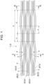
- Fig. 1 illustrates a configuration of the optical fiber ribbon 1 according to the first embodiment.
- the optical fiber ribbon 1 includes a plurality of sub-ribbons 2 and a coupling resin 3.
- the plurality of sub-ribbons 2 are arranged in parallel and intermittently coupled to each other in a longitudinal direction by the coupling resin 3.
- a coupling portion in which the adjacent sub-ribbons 2 are coupled to each other by the coupling resin 3 and a non-coupling portion 4 in which the adjacent sub-ribbons 2 are not coupled to each other are intermittently provided in the longitudinal direction.
- Fig. 1 illustrates the optical fiber ribbon 1 in a state in which the non-coupling portion 4 is expanded in the arrangement direction of the sub-ribbon 2.
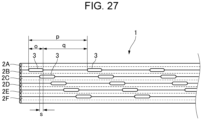
- the optical fiber ribbon 1 may satisfy 8 ⁇ o ⁇ 60 mm, 0.1 ⁇ o/p ⁇ 0.5, and 0 ⁇ s, in which o is a length in the longitudinal direction of the coupling resin 3 (that is, the coupling portion) between the adjacent sub-ribbons 2, q is a length in the longitudinal direction of the non-coupling portion 4 which is not coupled by the coupling resin 3, and s is the shortest distance in the longitudinal direction between the coupling resin s 3 adjacent to each other in the arrangement direction of the sub-ribbons 2.
- s is a negative value, it means that adjacent coupling resin s 3 at least partially overlap each other in the arrangement direction.
- the optical fiber ribbon 1 includes 2N optical fibers 21.
- a (2n+1)-th optical fiber 21 and a (2n+2)-th optical fiber 21, which are adjacent to each other, are integrated with the coating resin 22 in the longitudinal direction.
- the (2n+2)-th optical fiber 21 and a (2n+3)-th optical fiber 21, which are adjacent to each other are intermittently coupled to each other in the longitudinal direction by the coupling resin 3.
- N is an integer of 2 or more
- n is an integer of 0 or more.
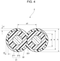
- the sub-ribbon 2 is formed by two optical fibers 21 and the coating resin 22 with which the periphery of the two optical fibers 21 are coated in the longitudinal direction.
- the adjacent sub-ribbons 2 are intermittently coupled to each other in the longitudinal direction by the coupling resin 3.
- the optical fiber ribbon 1 has 12 optical fibers that are optical fibers 21A to 21L.
- the optical fibers 21A and 21B, the optical fibers 21C and 21D, the optical fibers 21E and 21F, the optical fibers 21G and 21H, the optical fibers 21I and 21J, and the optical fibers 21K and 21L are integrated by the coating resin 22 in a state in which the respective two optical fibers are continuously in contact with each other in the longitudinal direction, and six sub-ribbons that are sub-ribbons 2A to 2F are formed.
- sub-ribbons 2A and 2B, the sub-ribbons 2B and 2C, the sub-ribbons 2C and 2D, the sub-ribbons 2D and 2E, and the sub-ribbons 2E and 2F are intermittently coupled to each other by the coupling resin 3 while being in contact with each other.
- Each of the optical fibers 21 has a glass fiber 211 and a coating layer 212.
- the glass fiber 211 includes, for example, a core and a cladding.
- the coating layer 212 is formed of a resin that covers a periphery of the glass fiber 211.
- the coating layer 212 may include two coating layers instead of one layer, and may further include a colored layer.
- the coating resin 22 is formed of a resin material such as an acrylic ultraviolet curable resin or an epoxy ultraviolet curable resin.
- the coating resin 22 is formed such that a thickness of a part covering an upper surface and a lower surface of the optical fiber 21 is substantially equal to a thickness of a part covering a side surface of the optical fiber 21.
- the coating resin 22 covers a periphery of the optical fiber 21 such that a thickness t1 in a thickness direction of the sub-ribbon 2 is substantially equal to a thickness t2 in the arrangement direction of the sub-ribbon 2.
- the thickness direction of the sub-ribbon 2 is a direction perpendicular to the arrangement direction and the longitudinal direction of the sub-ribbon 2.
- a recessed portion 221 is formed between the optical fibers 21.
- the sub-ribbon 2 may satisfy, for example, h ⁇ a + 40 ( ⁇ m) and g ⁇ 1.0a ( ⁇ m) in which h ( ⁇ m) is the maximum value of the thickness of the sub-ribbon 2, a ( ⁇ m) is the outer diameter of the optical fiber 21, and g ( ⁇ m) is the thickness of the sub-ribbon 2 at the recessed portion 221 of the coating resin 22. More preferably, the sub-ribbon 2 may satisfy h ⁇ a + 30 ( ⁇ m) and g ⁇ 0.9a ( ⁇ m).
- the thickness of the sub-ribbon 2 refers to a size in the thickness direction of the sub-ribbon 2.
- the coupling resin 3 is formed on one side of the plurality of sub-ribbons 2 arranged in parallel.
- the coupling resin 3 is formed on an upper side of the plurality of sub-ribbons 2 in this example, and may be formed on a lower side.
- the coupling resin 3 does not protrude outward from the outermost peripheral position of the sub-ribbon 2 in the thickness direction of the sub-ribbon 2.
- a position of an upper end of the coupling resin 3 is lower than a virtual line VL connecting upper ends of the sub-ribbons 2.
- the coupling resin 3 is formed in a range that does not exceed a distance between apexes V of the opposing optical fibers 21 of the adjacent sub-ribbons 2. Specifically, as illustrated in Fig. 5 , L1 > L2 is satisfied, in which L1 is a distance in the arrangement direction between the apexes V of the opposing optical fibers 21 of the adjacent sub-ribbons 2, and L2 is the length in the arrangement direction of the coupling resin 3.
- the apex V of the optical fiber 21 is a point at which the thickness of the optical fiber 21 is maximum in the thickness direction of the sub-ribbon 2 and is a point at which a virtual line extending from the center of the optical fiber 21 in the thickness direction intersects an outer periphery of the optical fiber 21.
- the coupling resin 3 is formed of a resin material such as an acrylic ultraviolet curable resin or an epoxy ultraviolet curable resin.
- the coupling resin 3 may be formed of the same resin material as the coating resin 22.
- the coupling resin 3 has an elongation at break of more than 250% and 500% or less.
- the coupling resin 3 has a tear strength of 0.25N or more.
- the coupling resin has a Young's modulus of 50 MPa or less.
- d2 is a distance between centers of the opposing optical fibers 21 (the (2n+2)-th optical fiber 21 and (2n+3)-th optical fiber 21) of the adjacent sub-ribbons 2.
- the optical fiber ribbon 1 is configured such that the distance d2 between the centers of the opposing optical fibers 21 of the adjacent sub-ribbons 2 is larger than a distance d1 between centers of two optical fibers 21 in the sub-ribbon 2.
- the optical fiber is configured such that d1 is larger than 200 ⁇ m and d2 is larger than 200 ⁇ m.
- the plurality of sub-ribbons 2 are intermittently coupled, and therefore, the flexibility of the optical fiber ribbon 1 is improved, and the optical fiber ribbon can be stored in the optical cable at a high density.
- the optical fibers 21 are integrated for each sub-ribbon 2, and therefore, when the optical fibers 21 constituting the optical fiber ribbon 1 are collectively fusion-spliced, handling becomes easier as compared with a case where a plurality of optical fibers 21 which are not coupled are fusion-spliced. That is, the optical fiber ribbon 1 can achieve both the high density storage property and handleability during collective fusion splicing.
- the cost of equipment for manufacturing the optical fiber ribbon 1 can be reduced by reducing the number of dispensers for applying the coupling resin 3.
- the sub-ribbon 2 satisfies h ⁇ a + 40 ( ⁇ m) and g ⁇ 1.0a ( ⁇ m), and more preferably satisfies h ⁇ a + 30 ( ⁇ m) and g ⁇ 0.9a ( ⁇ m). Accordingly, the coating resin 22 can be more easily stripped by rubbing the coating resin 22 with the separation tool when the optical fiber 21 is separated from the sub-ribbon 2. For example, the single-fiber separation workability of the optical fiber 21 performed when inserting the glass fiber 211 of the coated optical fiber 21 into a multi-fiber connector is improved.
- the optical fiber ribbon 1 is configured such that d2 is larger than d1. Accordingly, when the plurality of optical fibers 21 constituting the optical fiber ribbon 1 are collectively fusion-spliced, workability of accommodating the plurality of optical fibers 21 in the groove of the fusion splicer is improved. In particular, when the pitch of the grooves of the fusion splicer is larger than the outer diameter of the optical fiber 21, the optical fiber 21 can be easily accommodated in the grooves of the fusion splicer.
- the adjacent sub-ribbons 2 are coupled to each other by the coupling resin 3 in a state in which the adjacent sub-ribbons 2 are in contact with each other. Accordingly, when the coupling resin 3 is applied, the coupling resin 3 easily remains between the sub-ribbons 2. As a result, manufacturability of the optical fiber ribbon 1 is improved, and cost reduction can be achieved.
- the coupling resin 3 does not protrude outward from the outermost peripheral position of the sub-ribbon 2 in the thickness direction of the sub-ribbon 2. Accordingly, when the optical fiber ribbon 1 is rolled and stored in the optical cable at a high density, it is possible to prevent the occurrence of transmission loss due to occurrence of micro-bend in the optical fiber 21 caused by the optical fiber 21 being pressed by the coupling resin 3.
- the coupling resin 3 when the coupling resin 3 is formed of the same resin material as the coating resin 22, adhesion is improved. Accordingly, unexpected separation between the coupling resin 3 and the coating resin 22 is less likely to occur in the steps until the optical fiber ribbon 1 is stored in the optical cable.
- the coupling resin 3 when the elongation at break of the coupling resin 3 is 250% or more, the coupling resin 3 appropriately follows the deformation of the optical fiber ribbon 1 when the optical fiber ribbon 1 is rolled and stored in the optical cable, and therefore, the coupling resin 3 is less likely to peel off unintentionally.
- the coupling resin 3 when the elongation at break of the coupling resin 3 is 500% or less, the coupling resin 3 is appropriately easily peeled off when the plurality of optical fibers 21 are manually separated, and workability is improved.
- the coupling resin 3 when the tear strength of the coupling resin 3 is 0.25 N or more, the coupling resin 3 is less likely to peel off unintentionally when the optical fiber ribbon 1 is rolled and stored in the optical cable.
- the Young's modulus of the coupling resin 3 is 50 MPa or less, the tear strength of the coupling resin 3 is reduced, and it is possible to effectively prevent the loss fluctuation during the intermediate post-branching in which the optical fiber 21 is taken out from the intermediate portion of the optical cable.
- the optical fiber ribbon 1 satisfies 8 ⁇ o ⁇ 60 mm, 0.1 ⁇ o/p ⁇ 0.5, and 0 ⁇ s.
- the plurality of optical fibers 21 constituting the optical fiber ribbon 1 are collectively fusion-spliced using the fusion splicer, the occurrence of replacement of the sub-ribbon 2 is prevented, and therefore, workability of the fusion splicing is improved.
- the uncoupled portion is long to some extent and the adjacent coupling resin s 3 do not overlap each other in the arrangement direction, and therefore, the flexibility of a ribbon can be ensured, and an increase in transmission loss when the optical cable is stored can be prevented.
- the coupling resin 3 does not protrude outward from the outermost peripheral position of the sub-ribbon 2 in the thickness direction of the sub-ribbon 2.
- the coupling resin 3 may protrude outward than the sub-ribbon 2 in the thickness direction of the sub-ribbon 2.
- the coupling resin 3 can be formed such that the thickness (protruding length) e of the portion protruding outward from the outermost peripheral position of the sub-ribbon in the thickness direction of the sub-ribbon 2 is 30 ⁇ m or more and 100 ⁇ m or less.
- the protruding length e is a length, in the thickness direction, between a position of an upper end of the coupling resin 3 and the virtual line VL (see Fig. 5 ) connecting the upper ends of the sub-ribbons 2.
- the coating resin 22 and the coating layer 212 are collectively stripped from the optical fiber ribbon 1 using the stripping holder, friction between the stripping holder and the coupling resin 3 increases. Accordingly, the coating resin 22 and the coating layer 212 are integrally stripped, and the workability of collectively stripping the coating is improved. In particular, when the protruding length of the coupling resin 3 is 30 ⁇ m or more, the friction between the stripping holder and the coupling resin 3 can be sufficiently increased.
- the protruding length of the coupling resin 3 exceeds 100 ⁇ m, and the optical fiber ribbon 1 is rolled and stored in the optical cable, there is a high possibility that the optical fiber 21 is pressed by the coupling resin 3 and micro bend loss occurs in the optical fiber 21. Therefore, the protruding length of the coupling resin is preferably 100 ⁇ m or less.
- the coupling resin 3 is formed in a range that does not exceed the distance between the apexes V of the opposing optical fibers 21 of the adjacent sub-ribbons 2.
- the coupling resin 3 may be formed in a range exceeding the distance between the apexes V of the opposing optical fibers 21 of the adjacent sub-ribbons 2.
- the coupling resin 3 may be formed such that a distance L2 in the arrangement direction of the coupling resin 3 is 220 ⁇ m or more (L2 is larger than L1 by about 10%).
- the contact area between the coupling resin 3 and the coating resin 22 is increased, and the coupling resin 3 is caught in the recessed portion 221 of the coating resin 22, and therefore, the adhesion of the coupling resin 3 is increased. Accordingly, the coupling resin 3 is less likely to peel off from the coating resin 22.
- center positions of the optical fibers 21 constituting the adjacent sub-ribbons 2 are arranged along the arrangement direction of the sub-ribbons 2.
- the center positions of the optical fibers 21 constituting the adjacent sub-ribbons 2 may be deviated in the thickness direction from the arrangement direction of the sub-ribbons 2.
- a distance between a straight line connecting the centers of the optical fibers 21 at both ends among the optical fibers 21 constituting the adjacent sub-ribbons 2 and the center of the optical fibers 21 other than those at both ends, that is, an arrangement step f is preferably 75 ⁇ m or less, and more preferably 50 ⁇ m or less.
- the arrangement step f is a larger one of lengths of perpendicular lines extending from center positions c2 and c3 of the optical fibers 21B and 21C to the straight line connecting center positions c1 and c4 of the optical fibers 21A and 21D.
- the surface of the glass fiber 211 of the optical fiber 21 may be damaged when the coating layer 212 of the optical fiber 21, the coating resin 22 of the sub-ribbon 2, and the coupling resin 3 are collectively stripped by the coating stripper.
- such a failure is less likely to occur, and workability during collective fusion is improved.
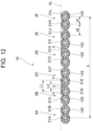
- optical fiber ribbon 10 according to a second embodiment will be described with reference to Figs. 10 to 13 .
- the same configuration as the optical fiber ribbon 1 according to the first embodiment is denoted by the same reference signs, and the detail description thereof will be omitted.
- the optical fiber ribbon 10 according to the second embodiment is different from the optical fiber ribbon 1 according to the first embodiment in a shape of a coating resin 122.
- the optical fiber ribbon 10 includes a plurality of sub-ribbons 2 (2A to 2F) and the coupling resin 3.
- the plurality of sub-ribbons 2 are arranged in parallel and intermittently coupled to each other in a longitudinal direction by the coupling resin 3.
- Each sub-ribbon 2 is formed of two optical fibers 21 (respective two of 21A to 21L) and the coating resin 122 with which the periphery of the optical fibers is coated in the longitudinal direction.
- the coupling resin 3 is formed on one side of the plurality of sub-ribbons 2 arranged in parallel.
- the coupling resin 3 is formed on the upper side of the plurality of sub-ribbons 2.
- the coupling resin 3 does not protrude outward from the outermost peripheral position of the sub-ribbon 2 in the thickness direction of the sub-ribbon 2.
- the coupling resin 3 is formed in a range that does not exceed the distance between the apexes V of the opposing optical fibers 21 of the adjacent sub-ribbons 2.
- the optical fiber ribbon 10 is configured such that the distance d2 between the centers of the opposing optical fibers 21 of the adjacent sub-ribbons 2 is larger than the distance d1 between centers of two optical fibers 21 in the sub-ribbon 2.
- the coating resin 122 is formed such that a thickness of a part covering a side surface of the optical fiber 21 is larger than a thickness of a part covering an upper surface and a lower surface of the optical fiber 21.
- the coating resin 122 covers the periphery of the optical fibers 21 such that the thickness t2 in the arrangement direction of the sub-ribbon 2 is larger than the thickness t1 in the thickness direction of the sub-ribbon 2.
- the thickness t1 is 5 ⁇ m
- the maximum value of the thickness t2 is 80 ⁇ m.
- the optical fiber ribbon 10 in which the distance d2 between the centers of the opposing optical fibers 21 of the adjacent sub-ribbons 2 is large. Accordingly, the manufacturability of the optical fiber ribbon 10 can be improved, and the cost reduction can be achieved.
- the same configuration as the optical fiber ribbon 1 according to the first embodiment can be applied to the configuration other than the thickness of the coating resin 122.
- the coupling resin 3 may protrude outward from the outermost peripheral position of the sub-ribbon 2 in the thickness direction of the sub-ribbon 2.
- the coupling resin 3 may be applied to a range exceeding the distance between the apexes V of the opposing optical fibers 21 of the adjacent sub-ribbons 2.
- the optical fiber ribbon 10 may be configured such that the distance between the straight line connecting the centers of the optical fibers 21 at both ends among the optical fibers 21 constituting the adjacent sub-ribbons 2 and the center of the optical fibers 21 other than the optical fibers at both ends, that is, the arrangement step, is preferably 75 ⁇ m or less, and more preferably 50 ⁇ m or less.
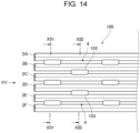
- an optical fiber ribbon 100 according to a third embodiment will be described with reference to Figs. 14 to 17 .
- the same configuration as the optical fiber ribbon 1 according to the first embodiment is denoted by the same reference signs, and the detail description thereof will be omitted.
- the optical fiber ribbon 100 according to the third embodiment is different from the optical fiber ribbon 1 according to the first embodiment in the configuration in which the sub-ribbon 2 is coupled to each other by the coupling resin 103.
- the optical fiber ribbon 100 includes a plurality of sub-ribbons 2 (2A to 2F) and the coupling resin 103.
- the plurality of sub-ribbons 2 are intermittently coupled to each other by the coupling resin 103 in the longitudinal direction in a state in which the sub-ribbons 2 are arranged in parallel at a predetermined distance.
- a coupling portion where the adjacent sub-ribbons 2 are coupled to each other by the coupling resin 103 and a non-coupling portion 4 where the adjacent sub-ribbons 2 are not coupled are intermittently provided in the longitudinal direction.
- each sub-ribbon 2 is formed of two optical fibers 21 (respective two of 21A to 21L) and the coating resin 22 with which the periphery of the optical fibers are coated in the longitudinal direction.
- the coupling resin 103 is provided between the adjacent sub-ribbons 2 so as to fill a gap between the sub-ribbons 2. That is, the adjacent sub-ribbons 2 are separated from each other, and the coupling resin 103 constitutes a bridge portion that cross-links the adjacent sub-ribbons 2.
- the optical fiber ribbon 100 is configured such that the distance d2 between the centers of the opposing optical fibers 21 of the adjacent sub-ribbons 2 is larger than the distance d1 between centers of two optical fibers 21 in the sub-ribbon 2.
- the outer diameter of the optical fiber 21 is 200 ⁇ m
- d1 is 200 ⁇ m
- d2 is 260 ⁇ m to 360 ⁇ m.
- the amount of resin used for the coating resin 22 can be reduced as compared with a case where the amount of resin for the coating resin 122 is increased in order to set the distance d2 between the centers of the opposing optical fibers 21 of the adjacent sub-ribbons 2 to an appropriate range as illustrated in Fig. 10 . Accordingly, the flexibility of the optical fiber ribbon 100 is improved, and the optical fiber ribbon can be stored in the optical cable at a high density.
- the optical fiber ribbon 100 may be configured such that the distance between the straight line connecting the centers of the optical fibers 21 at both ends among the optical fibers 21 constituting the adjacent sub-ribbons 2 and the center of the optical fibers 21 other than the optical fibers at both ends, that is, the arrangement step, is preferably 75 ⁇ m or less, and preferably 50 ⁇ m or less.
- an optical fiber ribbon 1000 according to the second embodiment will be described with reference to Figs. 18 to 21 .
- the same configuration as the optical fiber ribbon 1 according to the first embodiment is denoted by the same reference signs, and the detail description thereof will be omitted.
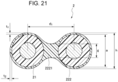
- the optical fiber ribbon 1000 according to the fourth embodiment is different from the optical fiber ribbon 1 according to the first embodiment in the shape of a coating resin 222 constituting the sub-ribbon 2 and the distance in the arrangement direction between the optical fibers 21.
- the optical fiber ribbon 1000 includes a plurality of sub-ribbons 2 (2A to 2F) and the coupling resin 3.
- the plurality of sub-ribbons 2 are arranged in parallel and intermittently coupled to each other in a longitudinal direction by the coupling resin 3.
- Each sub-ribbon 2 is formed of two optical fibers 21 (respective two of 21A to 21L) and the coating resin 222 with which the periphery of the optical fibers is coated in the longitudinal direction.
- the coupling resin 3 is formed on one side of the plurality of sub-ribbons 2 arranged in parallel.
- the coupling resin 3 is formed on the upper side of the plurality of sub-ribbons 2.
- the coupling resin 3 does not protrude outward from the outermost peripheral position of the sub-ribbon 2 in the thickness direction of the sub-ribbon 2.
- the coupling resin 3 is formed in a range that does not exceed the distance between the apexes V of the opposing optical fibers 21 of the adjacent sub-ribbons 2.
- the two optical fibers 21 are arranged without being in contact with each other.
- the optical fiber ribbon 1000 is configured such that the distance d2 between the centers of the opposing optical fibers 21 of the adjacent sub-ribbons 2 is smaller than the distance d1 between the centers of the two optical fibers 21 of the sub-ribbon 2.
- the coating resin 222 is formed such that a thickness of a part covering an upper surface and a lower surface of the optical fiber 21 is substantially equal to a thickness of a part covering a side surface of the optical fiber 21.
- the coating resin 22 covers a periphery of the optical fiber 21 such that a thickness t1 in a thickness direction of the sub-ribbon 2 is substantially equal to a thickness t2 in the arrangement direction of the sub-ribbon 2.
- the coating resin 222 has a coupling portion 2221 between the two optical fibers 21.
- the coating resin 222 is formed such that a thickness of the coupling portion 2221 is smaller than an outer diameter a of the optical fiber 21.
- the minimum thickness g of the coupling portion 2221 is 190 ⁇ m.
- the distance d2 between the centers of the opposing optical fibers 21 of the adjacent sub-ribbons 2 is smaller than the distance d1 between the centers of the two optical fibers 21 in the sub-ribbon 2, and therefore, the workability of accommodating the plurality of optical fibers 21 constituting the optical fiber ribbon 1000 in the grooves of the fusion splicer is improved when the plurality of optical fibers 21 are collectively fusion-spliced.
- the optical fibers 21 are arranged in the sub-ribbon 2 without being in contact with each other, and the thickness of the coupling portion 2221 constituted by a part of the coating resin 222 is smaller than the outer diameter a of the optical fibers 21, and therefore, the optical fiber ribbon 1000 in which the distance between the centers of the opposing optical fibers 21 of the adjacent sub-ribbons 2 is small can be stably produced. Accordingly, the manufacturability of the optical fiber ribbon 1000 can be improved, and the cost reduction can be achieved.
- the same configuration as the optical fiber ribbon 1 according to the first embodiment can be applied to the configuration other than the shape of the coating resin 222 constituting the sub-ribbon 2 and the distance in the arrangement direction between the optical fibers 21.
- the coupling resin 3 may protrude outward from the outermost peripheral position of the sub-ribbon 2 in the thickness direction of the sub-ribbon 2.
- the coupling resin 3 may be applied to a range exceeding the distance between the apexes V of the opposing optical fibers 21 of the adjacent sub-ribbons 2.
- the optical fiber ribbon 1000 may be configured such that the distance between the straight line connecting the centers of the optical fibers 21 at both ends among the optical fibers 21 constituting the adjacent sub-ribbons 2 and the center of the optical fibers 21 other than the optical fibers at both ends, that is, the arrangement step, is preferably 75 ⁇ m or less, and more preferably 50 ⁇ m or less.
- the coupling resin s 3 and 103 may be formed of a material containing a pigment.
- the colors of the coupling resin s 3 and 103 facilitate identification of the optical fiber ribbons 1, 10, and 100.
- the coupling resin s 3 and 103 may be formed such that they have a color different from that of the coating resin 22. Accordingly, when a worker visually checks the formation state of the coupling resin 3, the coupling resin 3 can be easily identified.
- the coupling resin s 3 and 103 may each have at least two colors.
- the coupling resin 3 coupling the sub-ribbon 2A and the sub-ribbon 2B and the coupling resin 3 coupling the sub-ribbon 2B and the sub-ribbon 2C may be formed in different colors.
- the numbers of the large number of optical fiber ribbons 1, 10 and 100 can be identified by differentiating the combination of the colors of the plurality of coupling resin s 3 and 103 formed in the optical fiber ribbons 1, 10 and 100. Accordingly, the production efficiency of the optical fiber ribbon can be improved, and the cost reduction can be achieved.
- the coupling resin s 3 and 103 may contain voids.
- the coupling resin s 3 and 103 are soft and easily extend. Therefore, the optical fiber ribbons 1, 10, and 100 have flexibility, and the coupling resin s 3 and 103 are less likely to peel off from the sub-ribbon 2 and the ribbon state is easily maintained even when the optical fiber ribbons 1, 10, and 100 are rolled.
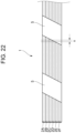
- the optical fiber ribbons 1, 10, and 100 may be provided with a marking on the coupling resin 3 and 103 or the coating resin 22 and 122 in the arrangement direction of the sub-ribbon 2.
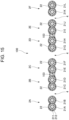
- a marking 5 is formed such that a predetermined amount of deviation u is formed in the longitudinal direction of the optical fiber ribbon 1 between the adjacent sub-ribbons 2.
- the predetermined amount is set to be larger than 0.1 mm.
- the marking 5 has a parallelogram inclined obliquely in the longitudinal direction of the plurality of sub-ribbons 2, and a plurality of markings 5 are provided at predetermined intervals in the longitudinal direction of the sub-ribbon 2.
- the marking 5 can be formed by printing using, for example, an ink jet printer.
- the marking 5 does not form a predetermined shape pattern. Accordingly, it is easy to detect the replacement of the sub-ribbon 2, and the plurality of optical fibers 21 can be prevented from being coupled in a state in which the plurality of optical fibers 21 are replaced in the fusion splicing operation.
- the predetermined amount is larger than 0.1 mm, the deviation of the marking is larger than the manufacturing variation in the length of the optical fiber 21, and therefore, the deviation of the marking is easily identified. Accordingly, the replacement of the sub-ribbon can be more reliably detected.
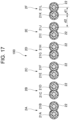
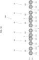
- o is the length in the longitudinal direction of the coupling resin 3 between the adjacent sub-ribbons 2
- s is the shortest distance in the longitudinal direction between the coupling resin s 3 adjacent to each other in the arrangement direction of the sub-ribbons 2.
- n is any one of 2, 3, 4, and 5.
- a region where three coupling resin s 3 overlap in the arrangement direction and a region where two coupling resin s 3 overlap in the arrangement direction alternately appear in the longitudinal direction.
- p 3 ⁇ (o + s).
- a region where the coupling resin s 3 do not overlap in the arrangement direction appears three times in a row in the longitudinal direction on a rear side of a region where two coupling resin s 3 overlap in the arrangement direction.
- the coupling resin s 3 are arranged to be deviated by s in the longitudinal direction without overlapping in the arrangement direction.
- the coupling resin s 3 are arranged in the arrangement direction such that adjacent coupling resin s 3 partially overlap each other in the arrangement direction.
- the formation pattern of the coupling resin s 3 is normally constant. Accordingly, when the worker visually checks the coupling resin 3 of the optical fiber ribbon 1, the worker can easily check the formation state of the coupling resin 3.
- the optical fiber ribbon 1 when the optical fiber ribbon 1 is configured such that the number of locations where the coupling resin s 3 overlap in the arrangement direction is two or less, the flexibility of the optical fiber ribbon is improved, and an increase in transmission loss when the optical fiber ribbon is stored in the optical cable is prevented.
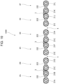
- the values of o, p, and s may change in the longitudinal direction of the optical fiber ribbon 1. In this case, it is preferable to change the values of o, p, and s while keeping the ratio of o:s:p constant in the longitudinal direction of the optical fiber ribbon 1.
- the coupling resin s 3 may be formed such that o, p, and s are gradually increased along the longitudinal direction. Alternatively, the coupling resin s 3 may be formed such that values of o, p, and s are increased after repeating the same value pattern a plurality of times in the longitudinal direction.
- the optical fiber ribbon 1 is formed such that the values of o, p, and s are increased while maintaining a constant ratio of o to s to p along the longitudinal direction. That is, o1 ⁇ o2 ⁇ o3, s1 ⁇ s2 ⁇ s3, and p1 ⁇ p2 ⁇ p3.
- the optical fiber ribbon 1 can be continuously produced while maintaining the same state without changing an operation of the device for applying the coupling resin 3. Accordingly, the loss of the optical fiber 21 can be reduced, and the cost reduction can be achieved.
- optical fiber ribbons 1 and 10 will be described with reference to Figs. 29 to 35 .
- the optical fiber ribbons 1 and 10 will be described below as an example, and this arrangement configuration can also be applied to the optical fiber ribbon 100.
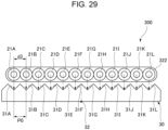
- a plurality of optical fibers can be collectively fusion-spliced by using a mass fusion splicer (not illustrated).
- the mass fusion splicer is provided with a V-groove base 30 having a plurality of (12 in this example) V-grooves that are V-grooves 31A to 31L for arranging the optical fibers.
- a pitch PO of the V-grooves 31A to 31L is generally 250 ⁇ m in accordance with the international standard of an outer diameter of an optical fiber.
- Fig. 29 illustrates a fusion step for an optical fiber ribbon 300 in which an outer diameter of each of the optical fibers 21A to 21L is 250 ⁇ m.
- the optical fibers 21A to 21L are integrated by the coating resin 322 while being in contact with each other.
- a distance d3 between centers of adjacent optical fibers is 250 ⁇ m.
- the optical fibers 21A to 21L in a state in which the coating resin 322 with a predetermined length at a tip thereof is stripped are arranged above the V-groove base 30.
- the optical fibers 21A to 21L are arranged such that, for example, a center position 32 of the V-groove base 30 in a direction in which the V-grooves 31A to 31L are arranged in parallel coincides with a center position in a direction in which the optical fibers 21A to 21L are arranged in parallel.
- a clamp lid (not illustrated) of the mass fusion splicer is closed, and the optical fibers 21A to 21L are pressed down from the upper side by the clamp lid.
- the distance d3 between the centers of the optical fibers is equal to the pitch PO of the V-grooves
- the optical fibers 21A to 21L are arranged such that the centers thereof are located at the centers of the V-grooves 31A to 31L, respectively. Therefore, the optical fibers 21A to 21L are pressed down substantially vertically and are sequentially accommodated one by one in order in the V-grooves 31A to 31L, respectively.
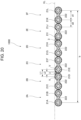
- Fig. 30 illustrates a fusion step for an optical fiber ribbon 400 in which the outer diameter of each of the optical fibers 21A to 21L is 200 ⁇ m.
- the optical fibers 21A to 21L are integrated by the coating resin 322 while being in contact with each other.
- a distance d4 between centers of adjacent optical fibers is 200 ⁇ m.
- the distance d4 between the centers of the optical fibers is smaller than the pitch PO between adjacent two of the V-grooves 31A to 31L, and therefore, the optical fibers 21A to 21L are gathered in a direction of the center position 32 of the V-groove base 30. Therefore, the optical fibers 21A to 21L cannot be accommodated in order in the V-grooves 31A to 31L. For example, optical fibers may not be accommodated in the V-grooves 31A and 31L at the ends.
- Fig. 31 illustrates a fusion step for the optical fiber ribbon 1 according to the first embodiment.
- the optical fiber ribbon 1 is constituted by 12 optical fibers that are optical fibers 21A to 21L each having an outer diameter of 200 ⁇ m
- the distance d1 between the centers of the optical fibers constituting the sub-ribbon 2 is 200 ⁇ m.
- the optical fiber ribbon 1 is fusion-spliced using the V-groove base 30 having V-grooves with a pitch PO of 250 ⁇ m
- the distance d2 between centers of the opposing optical fibers of the adjacent sub-ribbons 2 is preferably larger than 260 ⁇ m and 360 ⁇ m or less.
- the distance b between the centers of the optical fibers 21A and 21L at this time is 2.5 mm or more and 3.0 mm or less.
- the distance d1 between the centers of adjacent optical fibers that constitutes the sub-ribbon 2 is smaller than the pitch PO of the V-grooves, but the distance d2 between the centers of opposing optical fibers of adjacent sub-ribbons 2 is larger than the pitch PO of the V-grooves. Accordingly, the average distance between the centers of adjacent optical fibers is approximately 250 ⁇ m, so that when the clamp lid is pressed down, the optical fibers 21A to 21L are each guided along groove walls of the V-grooves to the corresponding V-grooves 31A to 31L and accommodated in the V-grooves 31A to 31L.
- the outer diameter of 200 ⁇ m means that the outer diameter is substantially 200 ⁇ m, and also includes, for example, the case where the outer diameter is within the range of 200 ⁇ m + 12 ⁇ m (that is, the outer diameter is within a range of 188 ⁇ m to 212 ⁇ m).
- Fig. 32 illustrates a fusion step for the optical fiber ribbon 10 according to the second embodiment.
- the optical fiber ribbon 1 is constituted by 12 optical fibers that are optical fibers 21A to 21L each having an outer diameter of 180 ⁇ m
- the distance d1 between the centers of the optical fibers constituting the sub-ribbon 2 is 180 ⁇ m.
- the optical fiber ribbon 10 is fusion-spliced using the V-groove base 30 having V-grooves with a pitch PO of 250 ⁇ m
- the distance d2 between centers of the opposing optical fibers of the adjacent sub-ribbons 2 is preferably larger than 284 ⁇ m and 384 ⁇ m or less.
- the distance b between the centers of the optical fibers 21A and 21L at this time is 2.5 mm or more and 3.0 mm or less.
- the distance d1 between the centers of adjacent optical fibers that constitutes the sub-ribbon 2 is smaller than the pitch PO of the V-grooves, but the distance d2 between the centers of opposing optical fibers of adjacent sub-ribbons 2 is larger than the pitch PO of the V-grooves. Accordingly, the average distance between the centers of adjacent optical fibers is approximately 250 ⁇ m, so that when the clamp lid is pressed down, the optical fibers 21A to 21L are each guided along groove walls of the V-grooves to the corresponding V-grooves 31A to 31L and accommodated in the V-grooves 31A to 31L.
- the outer diameter of 180 ⁇ m means that the outer diameter is substantially 180 ⁇ m, and also includes, for example, the case where the outer diameter is within the range of 180 ⁇ m + 10 ⁇ m (that is, the outer diameter is within a range of 170 ⁇ m to 190 ⁇ m).
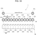
- Fig. 33 illustrates a fusion step of fusion-splicing the optical fiber ribbon 1 having 12 optical fibers that are optical fibers 21A to 21L each having an outer diameter of 200 ⁇ m using the V-groove base 30 having the V-groove with the pitch PO of 200 ⁇ m.
- the distance d1 between centers of the optical fibers constituting the sub-ribbon 2 is 200 ⁇ m.
- the distance d2 between centers of the opposing optical fibers of the adjacent sub-ribbons 2 is preferably 200 ⁇ m or more and 240 ⁇ m or less.
- the distance b between the centers of the optical fibers 21A and 21L at both ends of the plurality of optical fibers 21A to 21L constituting the optical fiber ribbon 1 is 2.4 mm or less.
- optical fiber ribbon 1 configured as described above, when collective fusion-splicing is performed using the V-groove base 30 having V-grooves with the pitch PO of 200 ⁇ m, all the optical fibers 21A to 21L easily enter the V-grooves 31A to 31L, and therefore, workability of the fusion splicing is improved.
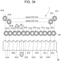
- Fig. 34 illustrates an optical fiber ribbon 1 having 12 optical fibers each having an outer diameter of 180 ⁇ m.
- the distance d1 between centers of the optical fibers constituting the sub-ribbon 2 is 180 ⁇ m.
- the distance d2 between centers of the opposing optical fibers of the adjacent sub-ribbons 2 is more than 224 ⁇ m and 264 ⁇ m or less.
- the distance b between the centers of the optical fibers 21A and 21L at both ends among the plurality of optical fibers 21A to 21L constituting the optical fiber ribbon 1 is 2.2 mm or more and 2.4 mm or less.
- optical fiber ribbon 1 configured as described above, when collective fusion-splicing is performed using the V-groove base 30 having V-grooves with the pitch PO of 200 ⁇ m, all the optical fibers 21A to 21L easily enter the V-grooves 31A to 31L, and therefore, workability of the fusion splicing is improved.
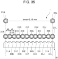
- Fig. 35 illustrates a fusion step of fusion-splicing the optical fiber ribbon 1 having 12 optical fibers that are optical fibers 21A to 21L each having an outer diameter of 180 ⁇ m using the V-groove base 30 having V-grooves with the pitch PO of 180 ⁇ m.
- the distance d1 between centers of the optical fibers constituting the sub-ribbon 2 is 180 ⁇ m. It is preferable that the distance d2 between centers of the opposing optical fibers of the adjacent sub-ribbons 2 is 180 ⁇ m or more and 216 ⁇ m or less.
- the distance b between the centers of the optical fibers 21A and 21L at both ends among the plurality of optical fibers 21A to 21L constituting the optical fiber ribbon 1 is 2.16 mm or less.
- optical fiber ribbon 1 configured as described above, when collective fusion-splicing is performed using the V-groove base 30 having V-grooves with the pitch PO of 180 ⁇ m, all the optical fibers 21A to 21L easily enter the V-grooves 31A to 31L, and therefore, workability of the fusion splicing is improved.
- Fig. 36 illustrates a configuration of a manufacturing apparatus 40 for the optical fiber ribbon 1.
- the optical fibers 21 are produced by drawing.
- the drawing is performed such that an outer diameter of the glass fiber 211 of the optical fiber 21 is approximately 125 ⁇ m, and a diameter of the outer coating layer 212 is approximately 200 ⁇ m.
- 12 optical fibers, which are optical fibers 21A to 21L wound around a supply bobbin 41, are prepared.
- the 12 optical fibers that are optical fibers 21A to 21L drawn out from the supply bobbin 41 pass through a coating die 42 of the manufacturing apparatus 40 in a state in which respective two of them are in contact with each other.
- the coating resin 22 is applied by the coating die 42 to each of outer peripheries of two optical fibers 21A and 21B, two optical fibers 21C and 21D, two optical fibers 21E and 21F, two optical fibers 21G and 21H, two optical fibers 21I and 21J, and two optical fibers 21K and 21L.
- a curing device 43 radiates ultraviolet rays to the optical fibers 21A to 21L coated with the coating resin 22, and the coating resin 22 is cured. Accordingly, six sub-ribbons 2A to 2F are formed.
- the coating device 44 includes, for example, five dispensers 44A to 44E.
- the five dispensers 44A to 44E apply the coupling resin 3 between the sub-ribbons 2A and 2B, the sub-ribbons 2B and 2C, the sub-ribbons 2C and 2D, the sub-ribbons 2D and 2E, and the sub-ribbons 2E and 2F which are in contact with each other.
- a curing device 45 radiates ultraviolet rays to the sub-ribbons 2A to 2F coated with the coupling resin 3, and the coupling resin 3 is cured. Accordingly, the optical fiber ribbon 1 in which the adjacent sub-ribbons 2 are intermittently coupled to each other by the coupling resin 3 in the longitudinal direction is completed. Then, the optical fiber ribbon 1 is wound around a winding-up bobbin 46.
- Fig. 37 is a view illustrating an example of a slotless optical cable 50 using the optical fiber ribbon 1 according to the present embodiment.
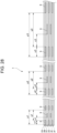
- Fig. 38 is a view illustrating an example of a slot optical cable 60 using the optical fiber ribbon 1 according to the present embodiment.
- the optical cable 50 illustrated in Fig. 37 is a slotless optical cable including a cylindrical tube 51 and a plurality of optical fiber ribbons 1.
- the plurality of optical fiber ribbons 1 are covered with the tube 51 while being stranded. Specifically, the plurality of optical fiber ribbons 1 are stranded with one another in a state in which each optical fiber ribbon 1 is rolled.
- a plurality of intervenient layers (tension fibers or the like) 52 are accommodated to fill gaps between the optical fiber ribbons 1.
- a sheath 53 is formed around the tube 51. Tension members 54 and tear strings 55 are embedded in the sheath 53.
- the intermittently coupled optical fiber ribbons 1 according to the present embodiment are covered with the tube 51 while being stranded, and therefore, deterioration in transmission characteristics of the optical cable 50 can be prevented.
- the occurrence of a failure can be prevented when the intermittently coupled optical fiber ribbons 1 are taken out from the optical cable 50 and subjected to fusion splicing.
- the optical cable 60 illustrated in Fig. 38 is a slot optical cable that has optical fiber ribbons 1 and a slot rod 62 having a plurality of slot grooves 61.
- the above slot grooves 61 are provided in a radial shape in the slot rod 62 having tension members 63 at a center thereof.
- the plurality of slot grooves 61 may be provided, for example, in a shape stranded in a spiral shape or an SZ shape in the longitudinal direction of the optical cable 60.
- a sheath 64 is formed around the slot rod 62.
- the intermittently coupled optical fiber ribbon 1 according to the present embodiment is stored in the slot groove 61, and therefore, deterioration in the transmission characteristics of the optical cable 60 can be prevented. In addition, occurrence of a failure can be prevented when the intermittently coupled optical fiber ribbon 1 is taken out from the optical cable 60 and subjected to fusion splicing.
- samples No. 1 to No. 39 were prepared in which parameters including the length o in the longitudinal direction of the coupling resin 3, the shortest distance s between the coupling resin s 3 adjacent to each other in the arrangement direction, and the length q in the longitudinal direction of the non-coupling portion 4 which is not coupled by the coupling resin 3 were changed. Then, the transmission characteristics based on the transmission loss when the optical fiber ribbon 1 is used for the 432-fiber slotless optical cable 50, the failure of the optical fiber ribbon 1 during the fusion splicing, and the failure (optical fiber loosening) of the sub-ribbon 2 due to the adhesion failure of the coupling resin 3 were investigated. The results are shown in Table 1 below. [Table 1] sample No.
- the transmission loss is considered to be related to the length o in the longitudinal direction of the coupling resin 3, the length q in the longitudinal direction of the non-coupling portion 4, and the shortest distance s between the coupling resin s 3 adjacent to each other in the arrangement direction.
- the transmission loss was at a high level in the sample No. 7 in which o was 70 mm.
- o/p was 0.5 or less
- s was a positive value
- the failure during fusion splicing is considered to be related to the length o in the longitudinal direction of the coupling resin 3 and the length q in the longitudinal direction of the non-coupling portion 4. Specifically, in the samples No. 8 to No. 11 and No. 24 to No. 27 in which o/p was 0.08, failure occurred during the fusion splicing. In the samples No. 12, No. 13, No. 28, and No. 29 in which q/o was 2.13 or more, failure occurred during the fusion splicing. On the other hand, in all the samples in which o/p was 0.1 or more and q/o was 1.50 or less, no failure occurred during fusion splicing.
- the optical fiber loosening relates to the length o in the longitudinal direction of the coupling resin 3. Specifically, the optical fiber loosening occurred in the sample No. 1 in which o was 5 mm. On the other hand, in the samples in which o was 8 mm or more, no optical fiber loosening occurred.
- the samples No. 2 to No. 6, No. 14 to No. 20, and No. 30 to No. 36 had low-level transmission characteristics (0.21 dB/km or less), and had no failures during fusion splicing and no optical fiber loosening. That is, it was found that the optical fiber ribbon 1 satisfying the conditions of 8 ⁇ o ⁇ 60 mm, 0.1 ⁇ o/p ⁇ 0.5, and 0 ⁇ s had low transmission loss and good workability of fusion splicing.
- the number of the optical fibers 21 constituting the optical fiber ribbons 1, 10, and 100 is 12, and the number of the optical fibers 21 is not limited as long as the number is an even number of four or more.
- the number of the optical fibers 21 included in the sub-ribbon 2 is two, and the number of the optical fibers 21 included in the sub-ribbon 2 is not limited as long as the number is two or more.
- the sub-ribbon 2 may include three, four or more optical fibers 21 and the coating resin 22 with which the peripheries of the optical fibers 21 are coated.
Landscapes
- Physics & Mathematics (AREA)
- General Physics & Mathematics (AREA)
- Optics & Photonics (AREA)
- Optical Fibers, Optical Fiber Cores, And Optical Fiber Bundles (AREA)
- Mechanical Coupling Of Light Guides (AREA)
Applications Claiming Priority (2)
| Application Number | Priority Date | Filing Date | Title |
|---|---|---|---|
| JP2022112369 | 2022-07-13 | ||
| PCT/JP2023/025768 WO2024014488A1 (ja) | 2022-07-13 | 2023-07-12 | 光ファイバリボンおよび光ケーブル |
Publications (2)
| Publication Number | Publication Date |
|---|---|
| EP4556977A1 true EP4556977A1 (de) | 2025-05-21 |
| EP4556977A4 EP4556977A4 (de) | 2025-10-29 |
Family
ID=89536814
Family Applications (1)
| Application Number | Title | Priority Date | Filing Date |
|---|---|---|---|
| EP23839660.0A Pending EP4556977A4 (de) | 2022-07-13 | 2023-07-12 | Glasfaserband und optisches kabel |
Country Status (3)
| Country | Link |
|---|---|
| EP (1) | EP4556977A4 (de) |
| JP (1) | JPWO2024014488A1 (de) |
| WO (1) | WO2024014488A1 (de) |
Family Cites Families (19)
| Publication number | Priority date | Publication date | Assignee | Title |
|---|---|---|---|---|
| JP3664254B2 (ja) | 2002-11-06 | 2005-06-22 | 住友電気工業株式会社 | 光ファイバテープ心線及びその製造方法 |
| JP5697011B2 (ja) * | 2010-02-16 | 2015-04-08 | 古河電気工業株式会社 | 光ファイバケーブル、及び光ファイバケーブルの形成方法 |
| JP5779940B2 (ja) | 2011-03-30 | 2015-09-16 | 住友電気工業株式会社 | 光ファイバテープ心線の製造装置および製造方法 |
| JP2016075746A (ja) * | 2014-10-03 | 2016-05-12 | 住友電気工業株式会社 | 間欠型光ファイバテープ心線及びその製造方法 |
| JP6365459B2 (ja) | 2015-08-06 | 2018-08-01 | 住友電気工業株式会社 | 光ファイバテープ心線、光ファイバケーブルおよび光ファイバコード |
| JP6569429B2 (ja) | 2015-09-25 | 2019-09-04 | 住友電気工業株式会社 | 光ファイバテープ心線 |
| JP6657976B2 (ja) | 2016-01-13 | 2020-03-04 | 住友電気工業株式会社 | 間欠連結型光ファイバテープ心線および光ケーブル |
| JP2017134360A (ja) | 2016-01-29 | 2017-08-03 | 住友電気工業株式会社 | 光ファイバテープ心線および光ケーブル |
| JP7052727B2 (ja) * | 2016-12-06 | 2022-04-12 | 住友電気工業株式会社 | 間欠連結型光ファイバテープ心線、その製造方法、光ファイバケーブルおよび光ファイバコード |
| ES2968206T3 (es) | 2017-07-11 | 2024-05-08 | Prysmian Spa | Cinta de fibras ópticas y procedimiento de producción de la misma |
| JP6453970B1 (ja) * | 2017-10-05 | 2019-01-16 | 株式会社フジクラ | 間欠連結型光ファイバテープ、及び、間欠連結型光ファイバテープの製造方法 |
| AU2018401777B2 (en) * | 2018-01-15 | 2024-07-11 | Prysmian S.P.A. | An optical fiber ribbon and a method and system of producing the same |
| JP2020204687A (ja) | 2019-06-17 | 2020-12-24 | 住友電気工業株式会社 | 光ファイバテープ心線、光ファイバケーブルおよび光ファイバテープ心線の製造方法 |
| EP4027180B1 (de) * | 2019-09-05 | 2024-11-06 | Sumitomo Electric Industries, Ltd. | Optisches faserband, optisches faserkabel und mit verbinder versehenes optisches faserkabel |
| AU2019472715B2 (en) * | 2019-10-30 | 2022-11-03 | Fujikura Ltd. | Intermittently connected optical fiber ribbon and method for manufacturing intermittently connected optical fiber ribbon |
| CN111175887A (zh) * | 2020-02-13 | 2020-05-19 | 江苏亨通光电股份有限公司 | 光纤带、光缆以及光纤带的制造方法 |
| EP4231073B1 (de) * | 2020-10-19 | 2026-01-28 | Sumitomo Electric Industries, Ltd. | Optisches faserband |
| WO2022131099A1 (ja) * | 2020-12-18 | 2022-06-23 | 住友電気工業株式会社 | 光ファイバテープ心線 |
| JP2022112369A (ja) | 2021-01-21 | 2022-08-02 | 日油株式会社 | ポリカーボネート樹脂組成物及び成形品 |
-
2023
- 2023-07-12 WO PCT/JP2023/025768 patent/WO2024014488A1/ja not_active Ceased
- 2023-07-12 EP EP23839660.0A patent/EP4556977A4/de active Pending
- 2023-07-12 JP JP2024533739A patent/JPWO2024014488A1/ja active Pending
Also Published As
| Publication number | Publication date |
|---|---|
| WO2024014488A1 (ja) | 2024-01-18 |
| EP4556977A4 (de) | 2025-10-29 |
| JPWO2024014488A1 (de) | 2024-01-18 |
Similar Documents
| Publication | Publication Date | Title |
|---|---|---|
| US6731844B2 (en) | Identification of optical ribbons | |
| EP3553578B1 (de) | Glasfaserbandkern mit sporadischer verbindung, verfahren zur herstellung davon, glasfaserkabel und glasfasercord | |
| CN100430767C (zh) | 具有优先分离顺序的光纤带 | |
| CN101889229B (zh) | 易分裂的光导纤维带 | |
| CN105229510B (zh) | 光纤带芯线及光缆 | |
| EP3025174B1 (de) | Glasfaserband | |
| CN111033342A (zh) | 高光纤密度带状电缆 | |
| JP6362302B2 (ja) | 光ファイバテープ心線及び光ケーブル | |
| US11415769B2 (en) | Intermittent connection-type optical fiber tape core wire, optical fiber cable, and method for manufacturing intermittent connection-type optical fiber tape core wire | |
| WO2016163190A1 (ja) | ルースチューブ、ルースチューブ型光ファイバケーブル、ルースチューブの光ファイバテープの単心分離方法、ルースチューブの製造方法、及び、複数の光ファイバの集線方法 | |
| WO2008042171A2 (en) | Fiber optic ribbons having one or more predetermined fracture regions | |
| JP2011232733A (ja) | 光ファイバテープ心線、光ファイバケーブル、及び光ファイバテープ心線の製造方法 | |
| EP3978976B1 (de) | Kernader für glasfaserband, glasfaserkabel und verfahren von herstellung einer kernader für glasfaserband | |
| EP0953858A1 (de) | Faseroptische Bandleitung und faseroptisches Bandkabel | |
| JP2004206048A (ja) | 光ファイバテープ心線及びその製造方法 | |
| JP2013109172A (ja) | 光ファイバユニット及び光ケーブル | |
| JP3902201B2 (ja) | 光ファイバ素線及び光ファイバテープ心線 | |
| JP4412040B2 (ja) | 光ファイバテープユニット及び光ファイバケーブル | |
| CN110140072A (zh) | 高密度、低弯曲损耗光纤带电缆 | |
| EP3943992A1 (de) | Glasfaserbandkern mit intermittierender verbindung, glasfaserkabel und mit verbinder versehener glasfaserkord | |
| EP4556977A1 (de) | Glasfaserband und optisches kabel | |
| WO2021045201A1 (ja) | 光ファイバテープ心線、光ファイバケーブルおよびコネクタ付光ファイバコード | |
| US20230393350A1 (en) | Optical fiber ribbon and method for manufacturing optical fiber ribbon | |
| WO2005101080A1 (ja) | 光ファイバテープユニット及び光ファイバケーブル | |
| JP2012027131A (ja) | 光ファイバテープ心線および光ケーブル |
Legal Events
| Date | Code | Title | Description |
|---|---|---|---|
| STAA | Information on the status of an ep patent application or granted ep patent |
Free format text: STATUS: THE INTERNATIONAL PUBLICATION HAS BEEN MADE |
|
| PUAI | Public reference made under article 153(3) epc to a published international application that has entered the european phase |
Free format text: ORIGINAL CODE: 0009012 |
|
| STAA | Information on the status of an ep patent application or granted ep patent |
Free format text: STATUS: REQUEST FOR EXAMINATION WAS MADE |
|
| 17P | Request for examination filed |
Effective date: 20250116 |
|
| AK | Designated contracting states |
Kind code of ref document: A1 Designated state(s): AL AT BE BG CH CY CZ DE DK EE ES FI FR GB GR HR HU IE IS IT LI LT LU LV MC ME MK MT NL NO PL PT RO RS SE SI SK SM TR |
|
| DAV | Request for validation of the european patent (deleted) | ||
| DAX | Request for extension of the european patent (deleted) | ||
| A4 | Supplementary search report drawn up and despatched |
Effective date: 20250926 |
|
| RIC1 | Information provided on ipc code assigned before grant |
Ipc: G02B 6/44 20060101AFI20250922BHEP |