EP3925040B1 - Procédé et dispositif pour retirer une feuille de câble - Google Patents
Procédé et dispositif pour retirer une feuille de câble Download PDFInfo
- Publication number
- EP3925040B1 EP3925040B1 EP20704522.0A EP20704522A EP3925040B1 EP 3925040 B1 EP3925040 B1 EP 3925040B1 EP 20704522 A EP20704522 A EP 20704522A EP 3925040 B1 EP3925040 B1 EP 3925040B1
- Authority
- EP
- European Patent Office
- Prior art keywords
- cable
- foil
- sheath
- holding
- section
- Prior art date
- Legal status (The legal status is an assumption and is not a legal conclusion. Google has not performed a legal analysis and makes no representation as to the accuracy of the status listed.)
- Active
Links
Images




Classifications
-
- H—ELECTRICITY
- H02—GENERATION; CONVERSION OR DISTRIBUTION OF ELECTRIC POWER
- H02G—INSTALLATION OF ELECTRIC CABLES OR LINES, OR OF COMBINED OPTICAL AND ELECTRIC CABLES OR LINES
- H02G1/00—Methods or apparatus specially adapted for installing, maintaining, repairing or dismantling electric cables or lines
- H02G1/12—Methods or apparatus specially adapted for installing, maintaining, repairing or dismantling electric cables or lines for removing insulation or armouring from cables, e.g. from the end thereof
- H02G1/1297—Removing armouring from cables
-
- H—ELECTRICITY
- H02—GENERATION; CONVERSION OR DISTRIBUTION OF ELECTRIC POWER
- H02G—INSTALLATION OF ELECTRIC CABLES OR LINES, OR OF COMBINED OPTICAL AND ELECTRIC CABLES OR LINES
- H02G1/00—Methods or apparatus specially adapted for installing, maintaining, repairing or dismantling electric cables or lines
- H02G1/12—Methods or apparatus specially adapted for installing, maintaining, repairing or dismantling electric cables or lines for removing insulation or armouring from cables, e.g. from the end thereof
- H02G1/1273—Methods or apparatus specially adapted for installing, maintaining, repairing or dismantling electric cables or lines for removing insulation or armouring from cables, e.g. from the end thereof by pushing backwards insulation
-
- H—ELECTRICITY
- H02—GENERATION; CONVERSION OR DISTRIBUTION OF ELECTRIC POWER
- H02G—INSTALLATION OF ELECTRIC CABLES OR LINES, OR OF COMBINED OPTICAL AND ELECTRIC CABLES OR LINES
- H02G1/00—Methods or apparatus specially adapted for installing, maintaining, repairing or dismantling electric cables or lines
- H02G1/12—Methods or apparatus specially adapted for installing, maintaining, repairing or dismantling electric cables or lines for removing insulation or armouring from cables, e.g. from the end thereof
- H02G1/1285—Methods or apparatus specially adapted for installing, maintaining, repairing or dismantling electric cables or lines for removing insulation or armouring from cables, e.g. from the end thereof by friction, e.g. abrading, grinding, brushing
-
- H—ELECTRICITY
- H02—GENERATION; CONVERSION OR DISTRIBUTION OF ELECTRIC POWER
- H02G—INSTALLATION OF ELECTRIC CABLES OR LINES, OR OF COMBINED OPTICAL AND ELECTRIC CABLES OR LINES
- H02G1/00—Methods or apparatus specially adapted for installing, maintaining, repairing or dismantling electric cables or lines
- H02G1/12—Methods or apparatus specially adapted for installing, maintaining, repairing or dismantling electric cables or lines for removing insulation or armouring from cables, e.g. from the end thereof
- H02G1/1202—Methods or apparatus specially adapted for installing, maintaining, repairing or dismantling electric cables or lines for removing insulation or armouring from cables, e.g. from the end thereof by cutting and withdrawing insulation
- H02G1/1248—Machines
- H02G1/1251—Machines the cutting element not rotating about the wire or cable
- H02G1/1253—Machines the cutting element not rotating about the wire or cable making a transverse cut
- H02G1/1256—Machines the cutting element not rotating about the wire or cable making a transverse cut using wire or cable-clamping means
Definitions
- the invention relates to a method for removing a cable foil from a cable section of an electrical cable to be processed, according to the preamble of claim 1.
- cable foils are sometimes used for electromagnetic shielding, mechanical protection and/or moisture protection of other components of the cable, for example to protect electrical conductors, cable shield braids and insulators or dielectrics.
- electrical cables it is often important that an insulating layer which insulates the electrical conductor is protected against moisture. Even moisture in the form of steam can damage the insulation.
- a cable foil can be provided as a separating layer between a cable shield braid and the cable (outer) sheath, which makes the cable sheath easier to remove during a stripping process - or even makes it possible to remove it at all - since the cable sheath can otherwise get mechanically caught or stuck in a cable shield braid underneath when it is removed.
- the cable foils can also be referred to as “shielding foils", “insulating foils” or “protective foils”.
- the term “cable foils” chosen here is intended to cover all areas of application.
- Such cable foils can consist of a single base material, e.g. a layer of an insulating material, such as a plastic, or a layer of an electrically conductive material, such as a metal.
- composite foils are also often used, which consist of at least two layers, in particular of at least two layers of different base materials.
- the foil is manufactured with a number of embossings spaced apart from one another, which weaken the foil material. Manual stripping can be made easier in this way.
- the disadvantage is that the cable foil then is mechanically weakened in the area of the entire cable, including in the area of the cable where the cable foil is not to be removed. Intentionally weakening the foil material can therefore be counterproductive.
- the manufacturing process of the cable foil is significantly more complex, as the embossing must be applied in such a way that it does not penetrate the foil as much as possible, since the aforementioned moisture protection must usually be guaranteed.
- US 5,072,632 A relates to cable stripping machines which strip the ends of multi-core shielded and sheathed cables, whereby it is particularly intended to compress a cable shield braid of the cable along the longitudinal axis of the cable before cutting.
- US 2015/357094 A1 concerns a similar subject matter.
- the DE 43 27 356 A1 a device for at least partially stripping insulation from stranded conductors provided with insulation, with a cutting device that radially separates the insulation, a cutting device and a clamping device for the stranded conductor.
- the WO 2015/125129 A1 a method for removing a cable foil from an electrical cable by means of a laser
- the JP H06 22425 A relates to a device for stripping a cable sheath from an electrical conductor, which makes a cut in the cable sheath without severing the conductor.
- the EP 2 871 734 A1 relates to a device for removing an inner sheath of the electrical conductors of a cable, wherein a cable foil previously exposed from a cable shield braid is removed from a cable by means of compressed air and a milling head.
- the object of the present invention is to provide a method for removing a cable foil, in which the cable foil can be removed from the cable section to be processed simply, reliably and without damaging the cable.
- a method for removing a cable foil from a cable section of an electrical cable to be processed.
- the cable section to be processed can be a cable end piece or a cable window (section of the cable between the end pieces where the cable sheath has been removed).
- the cable section to be processed is at least partially stripped for electrical and/or mechanical connection or contacting with a connector, an electrical device and/or for electrical and/or mechanical fastening to a component independent of the cable (e.g. a device housing or a body part of a vehicle).
- a component independent of the cable e.g. a device housing or a body part of a vehicle.
- the cable section to be processed is electrically and/or mechanically connected to a connector, another cable and/or a ground terminal.
- the electrical cable can be any electrical cable with one or more inner conductors and/or with one or more outer conductors.
- the invention is particularly advantageously suitable for removing the cable foil from electrical cables with a large cross-section for high current transmission, for example in the vehicle sector, particularly preferably in the field of electromobility.
- the invention can be advantageously used with a single-core coaxial cable for transmitting electrical power, which in particular has a structure consisting of an external cable sheath, followed by a cable foil, followed by a cable shield braid, followed by a dielectric or insulator and finally followed by an inner conductor.
- a ring-shaped ground connection of a connector is often first connected to the cable shield braid during assembly, with the cable shield braid or the outer conductor being turned back after it has been exposed, which can simultaneously provide reliable strain relief. Before this, the cable foil must first be removed in the course of exposing the cable shield braid.
- the cable foil can be located anywhere within the cable relative to one or more inner conductors, any electrical insulator, any cable shield braid and the cable sheath.
- the invention can also be suitable for processing a cable section of a cable, the structure of which consists in particular of an external cable sheath, followed by a cable shield braid, followed by the cable foil and finally followed by further components, for example an insulator and one or more inner conductors.
- the cable foil can be partially exposed by at least partially stripping or removing the cable sheath and the cable shield braid underneath. It can also be provided that the cable sheath is removed and the cable shield braid is only raised or folded back, whereby the cable shield braid is folded over without further processing or also additionally cut to length and/or can be untangled.
- only the accessibility of the cable foil for further processing according to the invention must be ensured.
- the cable foil is compressed in the axial direction along the cable center axis before the cable foil is removed from the cable section to be processed.
- the inventor has recognized in the present case that pulling the cable foil off the cable in the axial direction can be simplified, in particular for long sections of the cable foil to be removed or in the case of cables with a large diameter, if the cable foil is previously compressed, preferably against the pulling direction.
- the cable foil on the cable can initially be loosened, which can make subsequent removal easier.
- a material-locking or adhesive connection between the cable foil and the underlying structures such as a cable shield braid or an insulator, can be at least partially released or loosened.
- compression is carried out against the winding direction of the cable foil.
- a sheath enveloping the cable foil is compressed in order to compress the cable foil indirectly.
- the sheath can compress the cable foil, in particular over an elongated section running along the axial direction.
- the (previously exposed) cable foil can also be compressed directly.
- indirectly compressing the cable foil using an enveloping sheath an even better result can be achieved, since the radially restricted mobility of the cable foil can enable more targeted compression along the axial direction.
- a cable sheath of the cable or a gripping means extending in the axial direction or a sheath applied to the at least partially exposed cable foil can be used as the sheath enveloping the cable foil.
- the sheath that surrounds the cable foil is preferably the cable sheath. However, it can also be a cable shield braid or an electrically insulating shield. Existing sheath structures can therefore advantageously be used to indirectly compress the cable foil.
- a sheath is applied to a previously exposed cable foil in order to compress the cable foil indirectly by compressing the sheath.
- the sheath preferably extends in the axial direction along a section of the cable foil to be removed, particularly preferably over the entire section of the cable foil that is to be removed.
- the sheath can be an elongated sheath, for example a flexible hollow body, e.g. a hose.
- the sheath can be designed to fit around the cable foil in a force-fitting manner, at least partially in a ring shape, preferably all the way around.
- the sheath can be axially slit, for example, in order to be applied to the cable foil by elastic bending.
- the sheath can also be a sleeve, in particular a non-elastic hollow body.
- a gripping means can also be provided to form the sheath.
- the gripping means can in particular be a component of the holding devices and/or fixing devices described below, which grip around the cable, the cable sheath or the cable foil.
- the cable sheath is cut before the cable foil is compressed.
- the cable sheath can preferably be cut all the way around in a ring shape and thus severed. However, it can also be provided to cut the cable sheath only partially around in a ring shape or in sections around in a ring shape and leave, for example, individual connecting webs.
- the cable sheath is at least partially pulled off the cable foil in the axial direction (so-called partial pull-off) before the cable foil is compressed.
- the cable foil is at least partially exposed in the cable section to be processed before the cable foil is compressed or further processed in any other way.
- the cable foil is exposed in such a way that it is accessible at least in the area in which the cable foil is to be severed.
- a cable sheath or an outer conductor/cable shield braid which is cut in a known manner, for example by a knife, and then severed, does not have to be completely removed from the cable before the cable foil is processed according to the invention.
- the severed cable sheath also referred to as the stripped piece, can remain on the cable; preferably, the severed cable sheath is moved at least a small distance towards the nearby cable end in order to expose a portion of the cable foil.
- the cable foil is compressed by holding the sheath at a first holding position and wherein the cable is held at a position in the axial direction spaced, first fixing position, after which the first holding position and the first fixing position are moved relative to each other.
- the first and further holding positions or fixing positions described below each refer to an axial position along the cable or the sheath and can thus be moved together with the cable or the sheath in relation to a surrounding, absolute coordinate system.
- the relative movement of the holding position to the fixing position can, for example, take place over an axial length of 10 cm or more, preferably over an axial length of up to 1 cm, particularly preferably over an axial length of up to 5 mm, very particularly preferably over an axial length of up to 1 mm, but for example also over an axial length of less than 1 mm.
- the first fixing position is located outside the cable section to be processed.
- the first holding position (and/or the further holding positions described below) can be located on a severed, front section of the cable sheath (stripping piece) and the first fixing position can be located on the section of the cable sheath or cable that is not processed within the scope of the invention.
- the distance to be maintained can be, for example, at least 10 cm, preferably at least 5 cm, particularly preferably at least 1 cm.
- the distance to be maintained is preferably selected such that the exposed section of the cable foil is not completely closed again by moving the cable sheath.
- the cable sheath is not displaced by the compressing movement to such an extent that the severed ends of the cable sheath touch each other and the piece of cable sheath that is to remain on the cable is displaced on the cable in the opposite direction to the feed direction, as this can affect the stripping length.
- the first holding position and the first fixing position are moved relative to one another by the first fixing position being advanced towards the first holding position.
- the holding position can be held immobile.
- Such a feed can be particularly advantageous if the first fixing position is on the section of the cable sheath that has not been cut off or on the section of the cable that is not to be processed.
- the fixing position can, for example, be an axial position on the cable at which a feed device holds the cable and moves it in or against a feed direction as part of the cable processing.
- An existing feed device and an existing fixing position can thus be advantageously reused for compressing the cable foil.
- the first holding position and the first fixing position are moved relative to one another by the first holding position being moved towards the first fixing position.
- the fixing position can be kept immobile.
- a combination i.e. delivery on both sides, is also possible.
- the cable foil is compressed sequentially in several sections along the cable center axis.
- section-by-section compression can be advantageous.
- the compression can preferably be carried out in a staggered sequence.
- it can be provided to initially compress a first section that is closest to the free end of the cable or the section of the cable to be processed, followed by a section that is arranged downstream of the first section in the axial direction opposite to the feed direction of the cable.
- a reverse sequence for compression in several sections or a chaotic sequence can also be provided.
- the cable foil is compressed in two, three, four, five or more sections.
- the number of sections to be compressed can be determined by the person skilled in the art depending on the length of the cable to be processed.
- the cable foil is compressed in sections that extend along the axial direction over an area of 2 cm or more, extend over an area of 3 cm or more, extend over an area of 4 cm or more, extend over an area of 5 cm or more or extend over an area of 10 cm or more.
- a first fixing pair can be formed, for example, from the first holding position and the first fixing position.
- a second fixing pair can be formed, for example, from the second holding position and the second fixing position.
- a third fixing pair can be formed, for example, from the third holding position and the third fixing position.
- a fourth fixing pair can be formed, for example, from the fourth holding position and the fourth fixing position.
- a fifth fixing pair can be formed, for example, from the fifth holding position and the fifth fixing position.
- the first holding position is closest to the free end of the cable or the cable section to be processed, with the second holding position being arranged downstream of the first holding position in the axial direction, opposite to the feed direction of the cable; this can continue for optionally available, further holding positions.
- the arrangement or sequence can be the same for the fixing positions.
- the first fixing position is used to form corresponding pairs with several holding positions, and wherein the first fixing position is sequentially delivered to the respective holding positions, while the holding positions remain unchanged.
- a first fixing position is used, which forms respective fixing pairs with several holding positions. Re-gripping can thus be avoided, particularly with regard to a fixing device.
- a first fixing pair can then be formed, for example, from the first holding position and the first fixing position.
- a second fixing pair can then be formed, for example, from the second holding position and the first fixing position.
- a third fixing pair can then be formed, for example, from the third holding position and the first fixing position.
- a fourth fixing pair can then be formed, for example, from the fourth holding position and the first fixing position.
- a fifth fixing pair can then be formed, for example, from the fifth holding position and the first fixing position.
- the first holding position is used to form corresponding pairs with several fixing positions, and wherein the first holding position is sequentially delivered to the respective fixing positions, while the fixing positions remain unchanged.
- the casing is held at the at least one holding position and/or at the at least one fixing position by means of a cutting device and/or by means of a forming tool.
- the cutting device intended for stripping the cable sheath can be used to securely grip the cable or cable sheath by partially cutting into the cable sheath at the holding position and/or the fixing position.
- a purely force-fitting Fixing of the cable or cable sheath at the holding position(s) or the fixing position(s) must be provided.
- the cable or the cable sheath is gripped by means of a forming tool in a force-fitting manner at the holding position(s) and/or the fixing position(s).
- the forming tool can in particular be a tool already used for other purposes in the context of cable processing, for example one or more blunt blades for heating or melting the cable foil, as described below.
- the mechanical load-bearing capacity of the cable foil is reduced at least partially in a ring shape, in sections or completely around the circumference in the region of an intended tear position.
- the mechanical load capacity is reduced symmetrically around the circumference of the cable foil.
- the mechanical load-bearing capacity of the cable foil is reduced along the cable center axis completely or in sections in the area of the cable section to be processed.
- predetermined breaking points can be introduced into the cable foil, the number and extent of which can be adapted to the application-specific cable, the cable foil and, if necessary, other parameters.
- the cable foil in the area of the intended tear position is embossed and/or perforated during the pre-processing, at least partially in a ring shape, completely or in sections, all the way around the circumference of the cable foil.
- the mechanical load-bearing capacity of the cable foil is reduced before the cable foil is compressed.
- this sequence allows the cable foil to be removed from the cable or cable section relatively easily by compressing and, if necessary, subsequently pulling it off.
- at least one outer layer of the cable foil facing away from the cable center axis is subjected to a thermal treatment, a chemical treatment, an abrasive treatment or a suction process, or is cut into, at least in the area of the intended tear position, or a removal aid is glued to the cable foil and pulled off. This process step takes place before the cable foil is compressed.
- the cable foil is only treated when it is removed or to assist in the removal of the cable foil, the cable foil can still provide its full protective effect (electromagnetic, mechanical and/or sealing) in the untreated sections of the cable. This means that the cable foil does not have to be manipulated in terms of its mechanical resilience during the manufacture of the cable, which also simplifies the manufacture of the cable.
- the cable foil is pre-treat the cable foil with a knife.
- the cable foil is not cut during the processing described above. This means that the cable components located under the cable foil cannot be damaged, especially if only the outer layer is treated.
- a cable shield braid is often made up of shielding strands made of tinned copper.
- the tin layer on the copper ("drawing skin") must not be damaged as a rule, as this can impair the mechanical strength of the cable due to the brittleness of the pure copper.
- a cable foil is often wrapped protectively around such a cable shield braid, and the invention can be used particularly advantageously for removing such a cable foil, as damage to the cable shield braid underneath can be ruled out.
- the cable foil to be removed is also arranged under a cable shield braid and on another component of the cable, in particular a dielectric or an insulator.
- the invention can also be used advantageously with such a cable structure, since damage to the dielectric or insulator can then be ruled out. Damage to the dielectric or insulator can, for example, have a negative impact on its mechanical load-bearing capacity and thus its long-term stability. Furthermore, the insulating or electrical properties of the dielectric/insulator can be impaired.
- the cable foil it is also possible to treat the cable foil completely or continuously, i.e. to treat the cable foil in areas of the cable foil below the outer layer using the above-mentioned variants for removal or to assist in removal, if this is not expected to affect the components of the electrical cable located under the cable foil.
- pre-processing is carried out before the removal of the cable foil, at least in the area of the intended tear position, by one of the variants (thermal treatment, chemical treatment, abrasive treatment, cutting, suction and/or stripping aid).
- a partially ring-shaped or ring-shaped circumferential crack is introduced into the cable foil at the intended crack position by the method according to the invention in such a way that the crack extends through the outer layer and preferably at least partially also through an inner layer of the cable foil located under the outer layer. This method step preferably takes place before the cable foil is compressed.
- a crack is introduced in the outer layer or in part of the outer layer in a partially ring-shaped manner, completely or in sections, all the way around the circumference of the cable foil and/or along the central axis of the cable.
- a crack is introduced in the outer layer or in part of the outer layer in a partially ring-shaped manner, completely or in sections, all the way around the circumference of the cable foil and/or along the central axis of the cable in the radial direction, completely through the cable foil, i.e. through the outer layer and through the inner layer.
- a crack that only partially penetrates the inner layer of the cable foil is also possible.
- a tear in the cable foil can represent a suitable predetermined breaking point or reduce the mechanical load-bearing capacity of the cable foil at the tear position to the desired extent.
- the type of tear i.e. length, depth and width and, if necessary, the number of tears, can be determined by the specialist for the specific application.
- the cable section to be processed is twisted and/or bent in such a way that the cable foil tears in the cable section to be processed, preferably in the intended tear position, in a partial ring shape or in a ring shape all the way around.
- This method step preferably takes place before the cable foil is compressed.
- the basic idea of this further development is to subject the cable foil to targeted mechanical stress at the corresponding point(s) after one of the above-mentioned pre-treatment variants in such a way that the cable foil tears preferably (but not necessarily exclusively) at the intended tear position.
- this crack can be widened by twisting and/or bending the cable section. If no crack has previously been introduced, but the cable foil has only been weakened mechanically (invisibly), the crack can also be created by twisting and/or bending the cable section to be worked on.
- the inventor has recognized that in particular a mechanical load based on torsion and/or bending can lead to the desired result.
- the pretreatment creates a tear at least only in the outer layer of the cable foil.
- the outer layer is often a plastic foil, while the inner layer - optionally present - is often designed as a metal layer.
- An inner layer designed in this way can be relatively easily broken or torn by twisting or bending to create a tear.
- the thermal treatment comprises a melting process and/or a cooling process.
- Parts of the cable foil can be melted away by a melting process.
- the cable foil can also be evaporated, particularly in the area of its outer layer.
- a cooling process can be advantageous in order to at least temporarily increase the brittleness of the cable foil, especially in the area of the outer layer.
- a freezing technique with the aid of liquid nitrogen or similar coolants can be provided for this purpose.
- At least one heated molding tool and/or at least one heating wire is used for the thermal treatment, in particular in order to melt or melt the cable foil.
- the forming tool can preferably be a concavely shaped device similar to a cutting tool. Regardless of the shape of the forming tool, a blunt cutting knife can be provided, for example, which does not cut through the cable foil during thermal pre-processing, but can only melt through it in a targeted manner via the contact surfaces of the cutting edge.
- the tool cutting edge can, for example, be narrower or smaller than 10 mm, preferably smaller than 5 mm, for example also smaller than 2 or smaller than 1 mm. However, the cutting edge is preferably wider than 1 mm and is approximately 5 mm. If necessary, the heated forming tool can also be the forming tool with which the cable sheath is cut to expose the cable foil.
- a heating wire, a heating coil or a similar device is used, for example in a concave form or a form adapted to the cable or even in a linear form.
- two, three, four, five or more forming tools and/or heating wires are used, which are arranged circumferentially around the cable in order to process the cable foil partially in a ring shape, completely or in sections circumferentially along the circumference of the cable foil.
- the cable foil is only partially or completely melted in the area of the outer layer. However, it can also be provided that the cable foil is completely melted or at least an inner layer that lies beneath the outer layer is partially melted.
- the cable, the at least one forming tool and/or the at least one heating wire are rotated during the thermal treatment.
- the at least one forming tool and/or the at least one heating wire are moved around the cable along the circumference of the cable during the thermal treatment.
- forming tools and/or heating wires or similar can be used which have a linear structure, i.e. which do not encompass the cable or at least only partially.
- a melting temperature is used for the melting process which is greater than the melting temperature of the outer layer of the cable foil, but lower than the melting temperature of the inner layer of the cable foil and/or the melting temperature of a cable shield braid or an insulator or dielectric (or another component) of the cable.
- a temperature is selected as the melting temperature that is higher than the melting temperature of the outer layer and the inner layer of the cable foil, but lower than the melting temperature of a cable shield braid or an insulator or dielectric (or another component) of the cable.
- the cable foil can therefore also be completely melted without damaging other components of the cable.
- a melting temperature can be provided which does not negatively affect the cable sheath, any cable shielding braid, any dielectric or insulator and/or the at least one inner conductor of the cable.
- any melting temperature can be used, especially if the melting process is very short and possibly only intended to melt the outer layer of the cable foil.
- the melting temperature of PET is 250 °C to 400 °C, which is significantly lower than the melting temperature of aluminum and the silicone often used as a cable sheath.
- a melting temperature above 250 °C to 300 °C may therefore be preferred.
- any melting temperature may be used, for example a melting temperature in the range of 100 °C to 1,000 °C (or more), 200 °C to 700 °C (or more) or 250 °C to 500 °C (or more).
- a melting temperature of 300 °C to 400 °C, in particular 360 °C to 380 °C may be advantageous.
- the cable foil is melted or removed using a directed (micro) flame, for example a gas flame, and/or using a laser.
- a directed (micro) flame for example a gas flame
- the cable is preferably rotated during the treatment.
- An acid or a base can be used, in particular an acid or base that only or essentially attacks the cable foil, in particular the outer layer of the cable foil.
- an acid or base By using an acid or base, the outer layer and/or the inner layer of the cable foil can be removed at least in the area of the intended crack position or at least reduced in terms of their mechanical load-bearing capacity.
- any chemical treatment can be used to reduce the mechanical load-bearing capacity, whereby a chemical reaction, in particular of the outer layer of the cable foil, can be triggered at least in the area of the intended crack position, for example an oxidation which reduces the mechanical load-bearing capacity of the cable foil.
- a suction process can also be provided for removing or assisting in the removal of the cable foil, wherein, for example, using negative pressure, a suction tool is applied at least in the area of the intended tear position, for example a concavely shaped suction tool, wherein the outer layer and/or inner layer or the cable foil can be pulled off or torn off at least in the area of the intended tear position.
- a suction tool is applied at least in the area of the intended tear position, for example a concavely shaped suction tool, wherein the outer layer and/or inner layer or the cable foil can be pulled off or torn off at least in the area of the intended tear position.
- the suction process can also be used in addition to or in support of other treatments, particularly for removing the cable foil.
- an abrasive treatment in particular a grinding or brushing process, can be provided at least in the region of the intended crack position in order to at least partially remove the outer layer of the cable foil, in particular in order to reduce the mechanical load-bearing capacity of the cable foil.
- a removal aid at least partially around the circumference of the cable foil or to bond it to the outer layer of the cable foil, whereby the cable foil or at least the outer layer of the cable foil can be removed or torn off when the removal aid is removed.
- the remaining part of the cable foil for example the inner layer, then has a reduced mechanical load-bearing capacity and can be vacuumed off or removed in some other way if necessary.
- a ring-shaped, section-shaped or partially circumferential cut in the cable foil using one or more knives, preferably shaped knives. If necessary, the cutting can be carried out in such a way that the cable sheath is simultaneously cut in a ring-shaped circumferential manner and the foil is perforated at least in the area of an upper layer.
- the mechanical load-bearing capacity of the cable foil is reduced by the pre-processing within the framework of the second module by reducing the torsional strength and/or the bending strength of the cable foil, in particular the outer layer of the cable foil, and/or by increasing the brittleness of the cable foil, in particular the outer layer of the cable foil, so that it breaks mechanically more easily.
- the susceptibility to the formation of cracks should be increased in the area where the mechanical load-bearing capacity has been reduced.
- one, two, three, four or more actuators in particular linear motors or driven cylinders
- at least one eccentric are used to twist the cable section to be processed and/or to bend it along at least one degree of freedom.
- actuators are provided in order to bend the cable section to be processed in at least two degrees of freedom. This makes it technically easy to form a break or crack in the area of the cable foil to be processed, the mechanical load-bearing capacity of which was previously reduced.
- the actuators are used to strike the free end of the cable section, preferably in a time sequence.
- a first actuator can be controlled to carry out a first strike against the free end, after which an opposite actuator carries out a strike, and after which another pair of actuators strikes the free end in a clockwise or anti-clockwise direction.
- the sequence of strikes can basically be arbitrary.
- the actuators strike the free end of the cable section several times, for example each actuator twice, three times, four times or even more often.
- a composite film made of at least two individual layers is used as the cable film, wherein the inner layer is formed from at least one of the individual layers and the outer layer from the other individual layer(s), and wherein the inner layer preferably has a higher mechanical brittleness (i.e. a higher tendency to break under mechanical influence) than the outer layer.
- Composite films can be understood as, for example, metallized plastic films or several individual films arranged one above the other.
- the method according to the invention thus also includes the use of a suitable cable foil for an electrical cable to be processed.
- the type of cable foil used means that the method according to the invention can be optimally tailored to the electrical cable. In principle, however, any electrical cable can be provided with any cable foil.
- a cable foil in the form of a composite foil consisting of two, three, four, five or more individual layers can be used.
- a cable foil can also consist of a single base material.
- a continuous polyester foil, PET foil or metal foil for example aluminum foil or copper foil
- the outer layer can comprise a first part of the foil thickness and the inner layer a second part of the foil thickness.
- the outer layer can also comprise the entire material.
- the cable foil does not necessarily have to have an inner layer.
- a composite film made of two individual layers is used as the cable film, with the inner layer being made of the individual layer with higher mechanical brittleness and the outer layer being made of the individual layer with lower mechanical brittleness. Accordingly, it can be provided that the inner layer of the cable film breaks more easily under mechanical stress than the outer layer of the cable film.
- a composite film made of a plastic, preferably PET (polyethylene terephthalate), and a metal, preferably aluminum, is used, wherein the outer layer is formed by a single layer of the plastic and the inner layer is formed by a further single layer of the metal.
- a cable foil designed in this way can thus have a brittle inner layer (for example a copper or aluminum layer) and a mechanically durable plastic outer layer (e.g. PET).
- the method according to the invention is particularly advantageous and effective for such composite foils, which are frequently used in electrical cables, since the durable outer layer can preferably be removed by one or more variants of the method or at least manipulated in such a way that it becomes brittle. Since the inner layer of such a composite foil is sensitive to mechanical stress without the protective outer layer, the cable foil can then be easily removed after removal of the outer layer at the intended tear position and compression according to the invention.
- the cable foil is removed from the cable section to be processed after the tear has been introduced by brushing the cable foil, blowing it off, unwinding it, stripping it off and/or pulling it off together with a cable sheath.
- the cable sheath is cut in a ring-shaped manner all the way around and is pulled off the cable lengthways essentially in the area of the intended tear position along the cable center axis in order to expose the cable foil in the area of the intended tear position.
- the cable foil can then be pretreated in order to reduce its mechanical load-bearing capacity, after which the cable foil is compressed according to the invention, and after which the cable sheath is pulled off the electrical cable completely in the longitudinal direction or lengthways along the cable center axis.
- the cable foil will adhere more strongly to the cable sheath than, for example, to an internal cable shield braid. Accordingly, the cable foil can advantageously be compressed by compressing the cable sheath and then slide over the inner cable shield braid or an inner conductor while it is pulled off with the cable sheath.
- the cutting device that was previously used for the partial stripping of the cable sheath can be used, in particular one or more stripping blades that are fed radially in the direction of the cable center axis and then strip the cable sheath and/or the cable foil axially, for example by a separate feed device pulling the cable out of the device against the feed direction with the cutting device partially closed.
- first cable foil can be provided between the cable sheath and the cable shield braid and a second cable foil can be provided between the dielectric or an insulator and the inner conductor.
- the invention can also be used to remove several cable foils from an electrical cable.
- a device for the automated removal of a cable foil from a cable section of an electrical cable that is to be processed.
- the device has at least one holding device to hold a sheath that at least partially envelops the cable foil in a first holding position along the cable center axis.
- the device also has a fixing device to hold the cable in a first fixing position.
- the holding device and the fixing device are designed such that they can be positioned relative to one another in order to compress the cable foil directly or indirectly.
- the device is designed to reduce the mechanical load-bearing capacity of the cable foil at least partially in a ring, in sections or completely around the area of a designated tear position in order to support the removal of the cable foil before the cable foil is compressed.
- the device is designed to subject at least one outer layer of the cable foil facing away from the cable center axis to a thermal treatment, a chemical treatment, an abrasive treatment and/or a suction process at least in the region of the intended tear position and/or to cut it and/or to stick a removal aid onto the cable foil and to peel it off.
- the sheath may preferably be the cable sheath or one of the alternatives already mentioned above.
- the fixing device can be fed along a feed direction for the cable to be processed onto the holding device in order to compress the cable foil.
- the holding device can be fed onto the fixing device against a feed direction for the cable to be processed in order to compress the cable foil.
- the feed direction is the direction along which the cable, for example starting from a cable drum, can be fed into the device with its free end or with the cable section to be processed.
- the holding device and/or the fixing device is designed to move to a plurality of positions spaced apart from one another in the axial direction in order to hold the sheath and to indirectly compress the cable foil by a relative feed movement of the holding device to the fixing device.
- the holding device is designed as a stripping knife, forming tool or other device that can be radially positioned on the cable.
- At least one heating wire, at least one forming tool, at least one cold supply device, at least one removal aid, at least one suction device, at least one cutting device and/or at least one supply device for chemical Substances may be provided to treat at least one outer layer of the cable foil, which is at least partially exposed in the region of the cable section to be processed, facing away from the cable center axis, in order to remove the cable foil or to at least reduce the mechanical load-bearing capacity of the cable foil in order to assist in the removal of the cable foil, wherein means may also be provided to twist and/or bend the cable section to be processed.
- a cutting device for cutting the cable is arranged downstream of the fixing device along the feed direction, and wherein a forming tool for melting or melting the cable foil in a predetermined tear position is arranged downstream of the cutting device along the feed direction, and wherein at least one linear actuator for twisting and/or bending the cable foil is arranged downstream of the forming tool along the feed direction.
- the method according to the invention is particularly advantageously suitable for use with a device for the automated removal of a cable foil, since the method according to the invention discloses a technically simple possibility of removing the cable foil from the electrical cable without damaging other components of the cable.
- This disclosure also relates to a system for assembling electrical cables, comprising a device for cutting the electrical cable to length and/or a device for stripping and/or stripping various layers of the electrical cable and/or a device for opening, setting up and/or folding back a cable shield braid and/or a device for applying and contacting a connector part, as well as a device for the automated removal of a cable foil according to the above statements.
- This disclosure also relates to a computer program product with program code means for carrying out a method according to the above and following statements when the program is executed on a control unit of a device for the automated removal of a cable foil.
- the control unit can be designed as a microprocessor. Instead of a microprocessor, any other device can be provided for implementing the control unit and/or control device, for example one or more arrangements of discrete electrical components on a Printed circuit board, a programmable logic controller (PLC), an application-specific integrated circuit (ASIC) or another programmable circuit, for example a field programmable gate array (FPGA), a programmable logic array (PLA) and/or a commercially available computer.
- PLC programmable logic controller
- ASIC application-specific integrated circuit
- FPGA field programmable gate array
- PLA programmable logic array
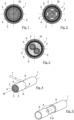
- the electrical cable 1 which is shown purely as an example and in a highly schematic manner with regard to the size ratios, is a coaxial cable with an inner conductor 2, which is electrically insulated from a cable shield braid or outer conductor 4 by an insulator/dielectric or insulation material 3.
- the insulation material 3 can be, for example, silicone rubber.
- a cable foil 5 is arranged around the cable shield braid 4.
- the electrical cable 1 is surrounded by a cable sheath 6. All components of the electrical cable 1 are arranged coaxially to a common cable center axis M.
- the cable shield braid 4 fulfills the task of electromagnetic shielding and the electrical return conductor and can, for example, be made of copper with a protective tin layer ("drawn skin") applied to the outer circumference.
- the invention can be used for any cable structure, in particular for a cable in which the cable shield braid or the outer conductor 4 is arranged directly under the cable sheath 6 and directly above the cable foil 5.
- the insulation material 3 can then follow directly under the cable foil 5, for example.
- the cable foil 5 can further improve the electromagnetic shielding, ensure mechanical stability and/or tightness, in particular against moisture, and prevent the cable sheath 6 from becoming wedged on the cable shield braid 4 or on the individual strands of the cable shield braid 4, which may make it possible to strip the cable sheath 6 from the cable shield braid 4 during stripping.
- several cable foils 5 can also be provided within the electrical cable 1, for example, another cable foil 5 can be provided between the insulation material 3 and the inner conductor 2 (not the case in the exemplary embodiment).
- the invention can thus also be used to remove several cable foils 5 from an electrical cable 1.
- the in Fig. 1 The electrical cable 1 shown is only one of a plurality of electrical cables 1 whose cable foil(s) 5 can be removed using the method according to the invention.
- the Figures 2 and 3 Basically, however, the invention is of course not to be understood as being limited to use with a specific type of cable 1.
- Fig. 2 shows a substantially Fig. 1 identical cable 1. However, this has four inner conductors 2, which are each electrically insulated from one another (not shown for the sake of simplicity).
- the invention is therefore not to be understood as being limited to the use of a cable 1 with a specific number of inner conductors 2.
- the invention is also not to be understood as being limited to a cable 1 in which insulation material 3 and/or cable shielding braid 4 are present at all.
- the invention can also be used, for example, to remove the cable foil 5 of an electrical cable 1 which has only one or more inner conductors 2 in the form of strands, which are each or jointly surrounded by a cable foil 5.
- Fig. 3 shows an example of another electrical cable 1 that can be processed according to the invention.
- the electrical cable 1 shown is particularly suitable as a cable 1 for use with electric vehicle drives.
- the cable 1 has two inner conductors 2, each of which is surrounded by the insulating material 3.
- the two separately insulated inner conductors 2 are surrounded by a filler material 3'.
- the cable shield braid 4, which is covered by the cable foil 5, runs on the filler material 3'.
- a cable sheath 6 is provided which envelops the cable foil 5.
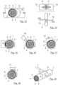
- Fig. 10 shows a further, optional step for turning the cable shield braid 4 inside out.
- the cable shield braid 4 is arranged directly under the cable sheath 6 and above the cable foil 5, the turning of the cable shield braid 4 can take place as part of exposing the cable foil 5, but possibly also after stripping the cable sheath 6.
- the Figures 4 to 10 each show the electrical cable 1 with the cable section A to be processed in an isometric view.
- the cable section A to be processed shown here is an end section of the electrical cable 1.
- the cable foil 5 in the cable section A to be processed is initially exposed at least partially, as for example in the Figures 4 and 5
- the cable sheath 6 can be cut at least partially all the way around in a known manner, in particular using a knife 7 which is only shown schematically, preferably in such a way that one or more webs or a narrow circumferential cable sheath ring remain and the cable foil 5 underneath thus remains as undamaged as possible.
- Fig. 4 shows a completely circumferential cut 8, which defines the length of the cable section A to be processed along the longitudinal axis or cable center axis M.
- the cutting and the removal or partial removal of the cable sheath 5 with the knife 7 is preferably carried out automatically.
- Fig. 5 It is shown that after the cut 8 has been made, the cable sheath 6 is at least partially pulled off the electrical cable 1 in the longitudinal direction (along the cable center axis M) in the direction of the arrow such that the cable foil 5 is at least partially exposed and accessible for the subsequent process steps.
- the cable foil 5 is wound in strip form onto the components of the cable 1 underneath, in this case the cable shield braid 4, or in a spiral shape, as shown in the Figures 5 to 9 and in the Figures 19 to 21 However, this is not necessarily the case.
- the mechanical load capacity of the cable foil 5 is to be reduced at least in the area of a planned tear position R P.
- the planned tear position R P is in Fig. 6 and is preferably located at or near the cut edge of the remaining cable sheath 6.
- Fig. 6 Furthermore, an enlarged section of the intended tear position R P is shown, which shows a schematic section through the cable foil 5, wherein the surrounding and inner areas of the cable 1 are not shown for the sake of simplicity.
- the cable foil 5 shown in the exemplary embodiment is a composite foil made of at least two individual layers, wherein the inner layer 10 is formed from at least one of the individual layers and the outer layer 9 from the further individual layer or layers (in this case a second individual layer), and wherein the inner layer 10 is preferably formed in such a way that it breaks mechanically more easily than the outer layer 9.
- a composite foil made of a plastic, preferably PET, and a metal, preferably aluminum or copper, is used, wherein the outer layer 9 consists of a single layer of the plastic and the inner layer 10 consists of a further single layer of the metal.
- a cable foil 5 consists of only a single individual layer or a single base material.
- the outer layer 9 can comprise the entire cable foil 5 or a partial area, with the inner layer 10 comprising the remaining partial area or no inner layer 10 being provided.
- several cable foils 5, each consisting of an individual layer (or several individual layers), are used layered on top of one another. This is also to be understood as a cable foil 5 or composite foil according to the invention.
- the mechanical load capacity is reduced at least partially in a ring shape, completely or in sections around the circumference of the cable foil 5.
- the mechanical load-bearing capacity of the cable foil 5 can be reduced by (partial) removal of the outer layer 9, embossing of the outer layer 9 or perforating the outer layer 9.
- a crack 11 is introduced into the cable foil 5 at the intended crack position R P in such a way that the crack 11 extends through the outer layer 9 (as in Fig. 6 shown) and preferably extends at least partially through the inner layer 10 of the cable foil 5 located beneath the outer layer 9.
- the mechanical load-bearing capacity of the cable foil 5 can be reduced in particular by reducing the torsional strength and/or the bending strength of the cable foil 5, in particular of the outer layer 9 of the cable foil 5, and/or by increasing the brittleness of the outer layer 9 of the cable foil 5.
- a crack 11 or any other optically visible influence on the cable foil 5 is not absolutely necessary - the mechanical influence can also be invisible, for example through chemical changes in the cable foil 5.
- a partially ring-shaped crack 11 is shown at the intended crack position R P or the outer layer 9 has been partially removed in a ring shape along the circumference of the cable foil 5.
- the predetermined breaking point created by this may be sufficient to subsequently easily remove the cable foil 5.
- the mechanical load capacity is reduced as completely as possible all the way around the circumference of the cable foil 5 or the outer layer 9 is removed as completely as possible.
- a partially ring-shaped crack 11 is shown here primarily to clarify and show the outer layer 9 and the inner layer 10 in a joint representation.
- a thermal treatment, a chemical treatment, an abrasive treatment, a suction process and/or an adhesive application and removal of a removal aid 12 can be provided in order to remove the cable foil 5 or to assist the removal of the cable foil 5, in particular by reducing the mechanical load-bearing capacity of the cable foil 5, in particular in the tear position R P , by means of the aforementioned measures.
- the cable foil 5 can also be cut.
- the thermal treatment can in particular include a melting process.
- a melting process In the Figures 13 to 15 Two possibilities for thermal pre-processing in the form of a melting process are shown schematically.
- Fig. 13 it is shown how two heated forming tools 13 are fed to both sides of the cable foil 5 or to the cable 1 in the area of the intended tear position R P.
- the heated contact surfaces 14 of the forming tools 13 can be, for example, blunt tool cutting edges, for example with a width of 1 mm or more, which, however, are not able to cut into the cable foil 5.
- only one forming tool 13 or three, four or even more forming tools 13 can be used; if necessary, after melting between the forming tools 13, webs can also remain in the outer layer 9 of the cable foil 5 along the circumference of the cable foil 5. If one or more forming tools 13 are used that do not completely enclose the cable foil 5, the forming tool 13 and/or the electrical cable 5 may be rotated during thermal pre-processing to allow melting along the circumference of the cable 1.
- the at least one forming tool 13 moves around the cable 1 during processing along the circumference of the cable 1.
- Fig. 14 another possible embodiment for the thermal treatment is shown, in which two heated forming tools 13 are again fed to both sides of the cable foil 5 or the cable 1.
- the forming tools 13 are offset in the axial direction and move past each other when fed to the cable 1. This enables advantageous centering of the cable 1 between the forming tools 13, which can improve the processing of the cable foil 5.
- FIG. 15 Another example of a thermal treatment for melting or melting the cable foil 5 at least in the area of the intended crack position R P is shown in Fig. 15
- a heating wire or a heating coil 15 is used here, whereby the cable 1 (alternatively or additionally also the heating wire 15) can be rotated during pre-processing, as shown by the arrow in Fig. 15 indicated.
- a melting temperature is used for the melting process which is greater than the melting temperature of the outer layer 9 of the cable foil 5, but is lower than the melting temperature of the inner layer 10 of the cable foil 5 and/or the melting temperature of other components of the cable 1, in particular the cable shield braid 4, the insulation material 3 and/or the at least one inner conductor 2 of the cable 1.
- a melting temperature 100 °C to 1,000 °C or more, preferably 200 °C to 800 °C, particularly preferably 300 °C to 700 °C and very particularly preferably 300 °C to 400 °C, for example 360 °C to 380 °C, can be provided.
- the melting temperature can be adjustable.
- the thermal treatment can also be designed in such a way that the cable foil 5 is thermally removed or melted over at least a partial length, if necessary over the entire length of the cable section A to be processed.
- a cooling process may also be carried out. This may involve, for example, freezing using liquid nitrogen or a other refrigerant may be provided at least in the area of the intended crack position R P , whereby the brittleness of at least the outer layer 9 of the cable foil 5 can be increased.
- a feed device 16 for chemical substances is shown, through which a chemical treatment can be carried out.
- an acid, a base or another chemical substance that triggers a reaction with the material of the cable foil 5, in particular with the outer layer 9, for example in the form of oxidation can be fed through the feed device 16, thereby reducing the mechanical load-bearing capacity of the cable foil 5.
- the aforementioned liquid nitrogen can also be fed through the feed device 16 (although a separate cold feed device can also be provided for this purpose).
- the cable 1 (or the feed device 16) can preferably be rotated during the feed of the chemical substance.
- a pretreatment with a removal aid 12 is shown.
- the removal aid 12 is glued to the outer layer 9 of the cable foil 5 at least in the area of the intended tear position R P or is integrally connected to the outer layer 9, after which the removal aid 12 is moved radially away from the cable center axis M in the direction of the arrow, whereby the cable foil 5, or at least the outer layer 9 of the cable foil 5, tears off. If necessary, the cable foil 5 can already be completely removed in this way.
- Several removal aids 12 can also be arranged distributed along the circumference of the cable foil 5, for example two, three, four or even more removal aids 12.
- the removal aid(s) 12 can have a concave shape in order to be able to be glued to the cable foil 5 over as large an area as possible. If necessary, a rotating movement of the removal aid 12 or of the cable 1 can also lead to a tearing of the cable foil 5.
- a suction process can also be provided instead of the removal aid 12.
- the cable foil 5 or the outer layer 9 of the cable foil 5 can be sucked in at least in the area of the intended tear position R P with a suction device (not shown) and thereby torn off or pulled off.
- a wire brush 17 is shown schematically, which is moved over the surface of the cable foil 5 or over the outer layer 9, for example by rotating the electrical cable 1, and thereby removes the outer layer 9 and/or the inner layer 10.
- comparable abrasive means can also be provided, for example a grinding device or a plastic brush.
- the Fig. 4 indicated and described knife 7 or the cutting device 22 described below can be reused.
- the cable section A to be processed is twisted and/or bent in such a way that the cable foil 5 tears in the cable section A, in particular at the intended tear position R P , in a ring-shaped circumferential manner, as in Fig. 7
- the fragility of the cable foil 5 is increased by reducing the mechanical load capacity of at least the outer layer 9 of the cable foil 5, i.e. the tendency to break under mechanical stress, at least in the area of the intended tear position R P , the cable foil 5 easily tears at the intended tear position R P after corresponding mechanical stress.
- a tear 11 can also form in the first place as a result.
- the cable foil 5 is completely severed after the mechanical stress on the cable section A to be processed.
- Actuators can be used to twist and/or bend the cable section A to be processed.
- Fig. 11 the use of four linear actuators 18 to bend the cable section A to be processed in two degrees of freedom. This allows a bending as in Fig. 7 movement shown by the arrows can be generated.
- any actuators can be provided to carry out such a movement or a similar movement, which leads to a mechanical load and ultimately a tearing of the cable foil 5.
- a rotation device or an eccentric 19 can be used to twist the cable section A to be processed.
- the representation of the Fig. 12 is exaggerated in its dimensions and should only be understood schematically.
- the cable 1 can be fix the cable 1 in the area of the intended tear position R P during the process step of twisting and/or bending.
- the previously described forming tools 13 can remain closed until the completion of the process step of twisting and/or bending.
- the cable 1 or at least the cable section A to be processed is first straightened after the twisting and/or bending process step, preferably before further process steps.
- two forming tools or blunt blades can be placed against the cable 1 for this purpose.
- the cable foil 5 can finally be compressed according to the invention in the axial direction along the cable center axis M, as in Fig. 8 indicated by the two arrows.
- the compression takes place before the cable foil 5 is removed from the section A to be processed, but otherwise at any time during the cable processing.
- the sequence of the process steps described above is therefore only to be understood as an example.
- the cable foil 5 is preferably compressed after the cable foil 5 has been at least partially exposed, particularly preferably after the mechanical load-bearing capacity of the cable foil 5 has been reduced and most preferably after the cable foil 5 has been torn off by twisting and/or bending.
- the cable foil 5 is compressed indirectly by compressing a sheath enveloping the cable foil 5.
- the cable foil 5 is compressed indirectly by compressing the cable sheath 6.
- indirect compression can also be carried out by compressing another sheath, for example by compressing a sheath subsequently applied to the exposed cable foil 5 (not shown).
- the cable foil 5 is finally removed from the cable section A to be processed. If, as shown in the embodiment, the cut-off cable sheath 6 has not yet been completely removed from the cable 1, the cable foil 5 can be pulled off together with the cable sheath 6 (cf. Fig. 9 ), since the cable foil 5, depending on the design, usually adheres well to the cable sheath 6.
- the cable foil 5 can be removed from the cable section A to be processed in any way after compression, for example by brushing, blowing, unwinding and/or stripping the cable foil 5. It can also be provided to remove the cable foil 5 and/or the cable sheath 6 by cutting the cutting device 22, for example a Fig.
- Fig. 10 is shown schematically and by way of example how the exposed cable shield braid 4 was folded back along the cable center axis M in order to be attached to a connector (not shown) and electrically connected to it, for example.
- the insulation material 3 could then be removed and the inner conductor 2 exposed and contacted with a connector (not shown).
- the cable section A to be processed can be a cable end piece as already shown. However, it can also be a cable window, as shown in the Figures 19 and 20 A cable window can be stripped in a known manner, for example by making two ring-shaped cuts 8 and a longitudinal cut 20 between the ring-shaped cuts 8 in the cable sheath 6, as shown in Fig. 19 Preferably, these process steps are also automated. The cable sheath 6 can then be removed, whereby the cable foil 5 located underneath in the embodiment is exposed. Finally, the steps already described above can be carried out in an analogous manner in order to remove the cable foil 5.
- two tear positions R P can also be provided or it can be provided that the mechanical load capacity is reduced at least partially in a ring shape, completely or in sections at two points distributed along the cable center axis M, after which the cable foil 5 is, for example, twisted between the intended tear positions R P , whereby it is at the intended Tear positions R P.
- the cable foil 5 can then be compressed, for example by moving the two ends of the opened cable sheath 6 towards each other in order to compress the cable foil 5 indirectly.
- the severed middle section of the cable foil 5 can then be easily removed.
- it can also be provided to reduce the mechanical load capacity of the cable foil 5 along the cable center axis M, as in Fig. 20 indicated by the dashed crack position R P.
- a device 21 for the automated removal of the cable foil 5 from a cable section A of an electrical cable 1 to be processed is shown schematically.
- At least one heating wire 15, at least one forming tool 13, at least one cold supply device (not shown), at least one removal aid 12, at least one suction device (not shown) and/or at least one feed device 16 for chemical substances can be provided in order to treat at least one outer layer 9 facing away from the cable center axis M of the cable foil 5 at least partially exposed in the area of the cable section A to be processed, in order to remove the cable foil 5 or to reduce the mechanical load capacity of the cable foil 5 at least in the area of the intended tear position R P to support the removal of the cable foil 5.
- Means can be provided (for example at least one linear actuator 18 and/or a rotation device or an eccentric 19) to twist and/or bend the cable section A to be processed.
- a cutting device 22 can also be provided for cutting and, if necessary, for removing or partially removing the cable sheath 6. All components can be designed to be adjustable, as in Fig. 21 indicated by the respective double arrows. As a means of twisting and/or bending the cable section to be processed, Fig. 21 A single linear actuator 18 is shown as an example, but as described above, any number of actuators of any design can be provided.
- a roller 23 is shown for stripping off the cut cable sheath 6. If the cable foil 5 is not removed or not completely removed from the cable 1 by stripping off the cable sheath 6, a nozzle 24 can also be provided, for example, in order to blow the cable foil 5 off the cable 1 using compressed air.
- a gripping device can be provided, for example the fixing device, holding device, at least one forming knife, etc., which grips the cable sheath 6 at an advantageous point, after which the gripping device and/or the cable 1 is moved in the axial direction in order to pull off the cable sheath 6 and the cable foil 5.
- the advantageous point is preferably as close as possible to the exposed cable section.
- the delivery of the gripping device to the cable 1 can be regulated via the contact pressure and not via a radial position.
- the device 21 shown as an example also has a cable feed device 25 for the electrical cable 1.
- the invention can advantageously be provided within a system 26 for assembling electrical cables 1.
- a system 26 for assembling electrical cables 1 is shown in Fig. 23 shown.
- An end section of a cable 1 is provided with a connector part 27 using several clocked devices or a device according to the method according to the invention.
- the system 26 can, for example, have a device 28 for cutting the cable 1 to length, a device 29 for stripping and/or stripping various layers of the cable 1, a device 30 for opening, setting up and/or folding back a cable shield braid 4, a device 31 for applying and contacting a connector part 27 and a device 21 for removing a cable foil 5 according to the above statements or as in the embodiment based on the Figures 1 to 22 described.
- other devices or the multiple use of devices within the system 26 can also be provided.
- the order in which the electrical cable 1 is processed can vary depending on the application.
- the system 26 shown is only to be understood as an example.
- FIG. 22 a section of a device 21 according to the invention is shown schematically.
- the cable foil 5 is compressed by holding the sheath 6 at a first holding position H 1 and the cable 1 is held at a first fixing position F 1 spaced apart from the first holding position H 1 in the axial direction, after which the first holding position H 1 and the first fixing position F 1 are moved relative to one another.
- the section a 1 of the cable foil 5 extending in the axial direction between the first holding position H 1 and the first fixing position F 1 can be compressed in order to facilitate the subsequent removal of the cable foil 5.
- the first fixing position F 1 is located outside the cable section A to be processed, as in Fig. 22 In particular, this allows an existing cable feed device, for example the cable feed device 25 of the Fig. 21 for fixing the cable 1 in the first fixing position F 1 and for the subsequent relative movement.
- the first fixing position F 1 is advanced to the first holding position H 1 .
- Sectional compression can be particularly suitable for long cable sections A. Any number of sections can be provided, in particular depending on the axial length of the cable section A. In Fig. 22 Three sections a 1 , a 2 , a 3 are indicated as examples.
- first fixing position F 1 can be particularly advantageous to use the first fixing position F 1 to form corresponding pairs with several holding positions H 1 , H 2 , H 3 , wherein the fixing position F 1 is sequentially advanced to the respective holding positions H 1 , H 2 , H 3 , while the holding positions H 1 , H 2 , H 3 remain unchanged.
- compression can first take place in the first section a 1 between the first holding position H 1 and the first fixing position F 1 , then in the second section a 2 between the second holding position H 2 and the first fixing position F 1 and then again in the third section a 3 between the third holding position H 3 and the first fixing position F 1 . In this way, any number of sections (even just one or two sections) can be compressed in chronological sequence.
- the casing 6 is held by means of the cutting device 22 and/or by means of the forming tool 13 at the at least one holding position H 1 , H 2 , H 3 and/or at the at least one fixing position F 1 .
- the cable feed device 25 can also advantageously be used to hold the casing 6 at the first fixing position F 1 . In principle, however, any holding device and/or any fixing device can be provided.
- a single holding device e.g. a single cutting device 22 or a single forming tool 13
- the holding device initially holds the cable sheath 6 at the first holding position H 1 , after which the fixing device is advanced to the holding device or is compressed along the first section a 1 .
- the holding device can then be released from the first holding position H 1 and advanced to the second holding position H 2 by moving the holding device and/or the cable 1 in the axial direction. Compression can then take place along the second section a 2 , followed by the third section a 3 , for which the same procedure can be followed.
- holding devices each of which is assigned to a holding position H 1 , H 2 , H 3 and is controlled one after the other for the sequential fixing of the cable sheath 6.
- the holding devices can thus be designed to be immobile or an axial displacement of the cable 1 during the sequential compression can be dispensed with.
Landscapes
- Processing Of Terminals (AREA)
- Removal Of Insulation Or Armoring From Wires Or Cables (AREA)
Claims (12)
- Procédé pour enlever une feuille de câble (5) d'une section de câble (A) à traiter d'un câble électrique (1),dans lequel la feuille de câble (5) est refoulée dans la direction axiale le long de l'axe médian (M) du câble avant que la feuille de câble (5) ne soit retirée de la section de câble (A) à traiter, dans lequel, pour assister le retrait de la feuille de câble (5), la capacité de charge mécanique de la feuille de câble (5) est réduite au moins en forme d'anneau partiel, par sections ou complètement sur le pourtour dans la zone d'une position de déchirure (RP) prévue, avant que la feuille de câble (5) ne soit refoulée, et dans lequel, pour retirer ou pour assister le retrait de la feuille de câble (5), avant que la feuille de câble (5) ne soit refoulée,caractérisé en ce queau moins une couche extérieure (9) de la feuille de câble (5) opposée à l'axe central du câble (M) est soumise à un traitement thermique, à un traitement chimique, à un traitement abrasif ou à une opération d'aspiration, au moins dans la zone de la position de déchirure prévue (RP), ou est entaillée, ou un auxiliaire de décollement (12) est collé sur la feuille de câble (5) et décollé.
- Procédé selon la revendication 1,
caractérisé en ce que
une gaine (6) enveloppant la feuille de câble (5) est comprimée afin de comprimer indirectement la feuille de câble (5). - Procédé selon la revendication 2,
caractérisé en ce que
on utilise comme gaine enveloppant la feuille de câble (5) une gaine de câble (6) du câble (1) ou un moyen de préhension s'étendant dans la direction axiale ou une gaine appliquée sur la feuille de câble (5) au moins partiellement dégagée. - Procédé selon la revendication 3,
caractérisé en ce que
la gaine de câble (6) est incisée avant que la feuille de câble (5) ne soit refoulée. - Procédé selon la revendication 3 ou 4,
caractérisé en ce que
la gaine de câble (6) est au moins partiellement retirée de la feuille de câble (5) dans la direction axiale avant que la feuille de câble (5) ne soit refoulée. - Procédé selon l'une quelconque des revendications 2 à 5,
caractérisé en ce que
la feuille de câble (5) est refoulée en maintenant la gaine (6) dans une première position de maintien (H1) et dans laquelle le câble (1) est maintenu dans une première position de fixation (F1) espacée de la première position de maintien (H1) dans la direction axiale, après quoi la première position de maintien (H1) et la première position de fixation (F1) sont déplacées l'une vers l'autre de manière relative. - Procédé selon la revendication 6,
caractérisé en ce que
la première position de fixation (F1) est située à l'extérieur de la section de câble (A) à traiter. - Procédé selon l'une quelconque des revendications 1 à 7,
caractérisé en ce que
la feuille de câble (5) est refoulée séquentiellement en plusieurs sections (a1, a2, a3) le long de l'axe central du câble (M). - Procédé selon la revendication 8,
caractérisé en ce que
le long de l'axe central du câble (M), on utilise différentes positions de maintien (H1, H2, H3) et/ou positions de fixation (F1) espacées dans la direction axiale, les sections à refouler (a1, a2, a3) s'étendant entre des paires de maintien formées chacune d'une position de maintien (H1, H2, H3) et d'une position de fixation (F1), après quoi, séquentiellement pour toutes les paires de maintien formées, leur position de maintien (H1, H2, H3) et leur position de fixation (F1) sont déplacées l'une vers l'autre de manière relative. - Procédé selon la revendication 9,
caractérisé en ce que
la première position de fixation (F1) est utilisée pour former des paires correspondantes avec plusieurs positions de maintien (H1, H2, H3), et dans lequel la première position de fixation (F1) est amenée séquentiellement sur les positions de maintien respectives (H1, H2, H3), tandis que les positions de maintien (H1, H2, H3) restent inchangées. - Procédé selon l'une quelconque des revendications 2 à 10,
caractérisé en ce que
la gaine (6) est maintenue dans ladite au moins une position de maintien (H1, H2, H3) et/ou dans ladite au moins une position de fixation (F1) au moyen d'un dispositif de coupe (22) et/ou au moyen d'un outil de formage (13). - Procédé selon l'une quelconque des revendications 1 à 11,
caractérisé en ce que
la section de câble (A) à traiter est tordu et/ou déformé de telle sorte que la feuille de câble (5) se déchire en forme d'anneau partiel ou en forme d'anneau périphérique dans la section de câble (A) à traiter.
Applications Claiming Priority (2)
| Application Number | Priority Date | Filing Date | Title |
|---|---|---|---|
| DE102019103486.8A DE102019103486B3 (de) | 2019-02-12 | 2019-02-12 | Verfahren und Vorrichtung zum Entfernen einer Kabelfolie |
| PCT/EP2020/053313 WO2020165086A1 (fr) | 2019-02-12 | 2020-02-10 | Procédé et dispositif pour retirer une feuille de câble |
Publications (3)
| Publication Number | Publication Date |
|---|---|
| EP3925040A1 EP3925040A1 (fr) | 2021-12-22 |
| EP3925040B1 true EP3925040B1 (fr) | 2025-01-15 |
| EP3925040C0 EP3925040C0 (fr) | 2025-01-15 |
Family
ID=69528852
Family Applications (1)
| Application Number | Title | Priority Date | Filing Date |
|---|---|---|---|
| EP20704522.0A Active EP3925040B1 (fr) | 2019-02-12 | 2020-02-10 | Procédé et dispositif pour retirer une feuille de câble |
Country Status (3)
| Country | Link |
|---|---|
| EP (1) | EP3925040B1 (fr) |
| DE (1) | DE102019103486B3 (fr) |
| WO (1) | WO2020165086A1 (fr) |
Families Citing this family (1)
| Publication number | Priority date | Publication date | Assignee | Title |
|---|---|---|---|---|
| US11710585B2 (en) * | 2019-03-20 | 2023-07-25 | Te Connectivity Solutions Gmbh | Method of removing foil shield from cable |
Citations (4)
| Publication number | Priority date | Publication date | Assignee | Title |
|---|---|---|---|---|
| DE4327356A1 (de) * | 1993-08-14 | 1995-02-16 | Abb Patent Gmbh | Vorrichtung zum Abisolieren von Litzenleitern |
| EP2871734A1 (fr) * | 2013-11-11 | 2015-05-13 | Schleuniger Holding AG | Dispositif permettant de retirer l'enveloppe intérieure du conducteur électrique d'un câble |
| EP3312956A1 (fr) * | 2016-10-18 | 2018-04-25 | Komax Holding AG | Procédé et dispositif pour dénuder un câble comprenant une gaine multicouches |
| US20180138672A1 (en) * | 2016-11-15 | 2018-05-17 | Schleuniger Holding Ag | Apparatus and method for removing an inner sheathing of electrical conductors |
Family Cites Families (14)
| Publication number | Priority date | Publication date | Assignee | Title |
|---|---|---|---|---|
| US3153358A (en) | 1962-05-24 | 1964-10-20 | Rex C Havens | Shielded wire stripper |
| US5072632A (en) * | 1991-01-23 | 1991-12-17 | The Boeing Company | Multiconductor cable stripper |
| JPH0622425A (ja) * | 1992-07-01 | 1994-01-28 | Fujikura Ltd | 電線被覆むき補助器 |
| DE10026714A1 (de) | 2000-05-30 | 2001-12-13 | Hueck Folien Gmbh | Verbundfolie, Verfahren zu ihrer Herstellung und ihre Verwendung |
| JP3790416B2 (ja) | 2000-11-06 | 2006-06-28 | 矢崎総業株式会社 | シールド電線の加工方法と加工装置 |
| DE102004047384B3 (de) | 2004-09-29 | 2006-01-12 | Siemens Ag | Kabel zur Übertragung von elektrischen Signalen |
| JP4298709B2 (ja) | 2006-01-26 | 2009-07-22 | 矢崎総業株式会社 | シールド電線の端末処理方法および端末処理装置 |
| DE202006003872U1 (de) | 2006-03-11 | 2007-07-19 | Leoni Kabel Holding Gmbh & Co. Kg | Kabel |
| US10476245B2 (en) * | 2014-02-24 | 2019-11-12 | Frisimos, Ltd. | Removing a metal shield from electrical cable |
| US9620919B2 (en) * | 2014-06-05 | 2017-04-11 | Asahi Seiki Co., Ltd. | Process for producing shield layer-cut electric wire |
| CN104494234B (zh) | 2014-12-18 | 2018-03-06 | 杭州临安天宏电讯材料有限公司 | 一种单面热熔铝塑复合箔及其制备方法 |
| EP3089294B1 (fr) | 2015-04-30 | 2019-07-31 | Komax Holding AG | Dispositif d'usinage de câble et procédé destiné à éliminer une feuille de blindage d'un câble rond à plusieurs fils, blindé |
| EP3163697B1 (fr) | 2015-10-29 | 2020-09-02 | Lisa Dräxlmaier GmbH | Séparation d'un blindage d'un câble coaxial |
| DE102016113004A1 (de) | 2016-07-14 | 2018-01-18 | Komax SLE GmbH & Co. KG | Vorrichtung zur Bearbeitung von Kabelenden |
-
2019
- 2019-02-12 DE DE102019103486.8A patent/DE102019103486B3/de active Active
-
2020
- 2020-02-10 EP EP20704522.0A patent/EP3925040B1/fr active Active
- 2020-02-10 WO PCT/EP2020/053313 patent/WO2020165086A1/fr not_active Ceased
Patent Citations (4)
| Publication number | Priority date | Publication date | Assignee | Title |
|---|---|---|---|---|
| DE4327356A1 (de) * | 1993-08-14 | 1995-02-16 | Abb Patent Gmbh | Vorrichtung zum Abisolieren von Litzenleitern |
| EP2871734A1 (fr) * | 2013-11-11 | 2015-05-13 | Schleuniger Holding AG | Dispositif permettant de retirer l'enveloppe intérieure du conducteur électrique d'un câble |
| EP3312956A1 (fr) * | 2016-10-18 | 2018-04-25 | Komax Holding AG | Procédé et dispositif pour dénuder un câble comprenant une gaine multicouches |
| US20180138672A1 (en) * | 2016-11-15 | 2018-05-17 | Schleuniger Holding Ag | Apparatus and method for removing an inner sheathing of electrical conductors |
Also Published As
| Publication number | Publication date |
|---|---|
| WO2020165086A1 (fr) | 2020-08-20 |
| EP3925040C0 (fr) | 2025-01-15 |
| DE102019103486B3 (de) | 2020-08-06 |
| EP3925040A1 (fr) | 2021-12-22 |
Similar Documents
| Publication | Publication Date | Title |
|---|---|---|
| EP4092850B1 (fr) | Procédé et dispositif d'enlèvement d'une feuille de câble | |
| EP3925041B1 (fr) | Procédé et dispositif permettant de produire un câble électrique | |
| EP3391512B1 (fr) | Procédé d'insertion d'un film isolant et au moins un conducteur électrique | |
| EP3811478B1 (fr) | Dispositif et procédé destinés à dénuder des câbles | |
| DE112018002202T5 (de) | Vorrichtung zur Verarbeitung eines Flechtschirms und Verfahren zum Verarbeiten eines Flechtschirmkabels | |
| EP2887475B1 (fr) | Procédé et dispositif de séparation d'un blindage d'un câble coaxial | |
| EP3312956B1 (fr) | Procédé et dispositif pour dénuder un câble comprenant une gaine multicouches | |
| EP3417514B1 (fr) | Système de contact pour la mise en contact d'une tresse de blindage et d'un élément de contact | |
| DE102020122412B4 (de) | Verfahren zum entfernen einer beschichtung eines kabels und vorrichtung zum entfernen einer beschichtung eines kabels | |
| EP4189793B1 (fr) | Dispositif et procédé de préparation d'un câble électrique | |
| DE102013008275B4 (de) | Verfahren zum Abisolieren eines mit Isolationsmaterial ummantelten Drahtes | |
| EP3447865B1 (fr) | Procédé d'enlèvement d'une partie d'une feuille écran d'un habillage de câble de ligne et dispositif d'enlèvement des feuilles permettant l'enlèvement d'une partie d'une feuille écran d'un habillage de câble de ligne à un point de rupture de l'habillage de câble de ligne | |
| EP3925040B1 (fr) | Procédé et dispositif pour retirer une feuille de câble | |
| EP4055674B1 (fr) | Procédé et dispositif de traitement d'un câble électrique | |
| EP3804048B1 (fr) | Dispositif et procédé servant à usiner une extrémité d'un câble électrique | |
| EP3820006B1 (fr) | Procédé d'enlèvement d'une feuille pour câble | |
| DE19958763C1 (de) | Verfahren zum Bearbeiten von mineral-isolierten Leitungen | |
| EP3550684B1 (fr) | Dénudage de conduites électriques par ultrasons | |
| EP3831586B1 (fr) | Procédé de fabrication d'un tuyau chauffable et dispositif de fixation associé | |
| CH720917A2 (de) | Abmantelungsgerät | |
| DE202022001574U1 (de) | Vorrichtung zur Vorschädigung von Trennhilfen oder Teilen davon aus thermoplastischem Gewebe und deren Entfernung von elektrischen Leitern | |
| EP4078744A1 (fr) | Appareil à dénuder pour câbles | |
| DE102006026502A1 (de) | Verfahren zum Herstellen einer elektrisch leitenden Kontaktierung zu einem Außenleiter eines mit einer Isolierung versehenen Koaxialkabels | |
| DE102009009743A1 (de) | Kabel sowie Verfahren und Vorrichtung zur Kabelentmantelung |
Legal Events
| Date | Code | Title | Description |
|---|---|---|---|
| STAA | Information on the status of an ep patent application or granted ep patent |
Free format text: STATUS: UNKNOWN |
|
| STAA | Information on the status of an ep patent application or granted ep patent |
Free format text: STATUS: THE INTERNATIONAL PUBLICATION HAS BEEN MADE |
|
| PUAI | Public reference made under article 153(3) epc to a published international application that has entered the european phase |
Free format text: ORIGINAL CODE: 0009012 |
|
| STAA | Information on the status of an ep patent application or granted ep patent |
Free format text: STATUS: REQUEST FOR EXAMINATION WAS MADE |
|
| 17P | Request for examination filed |
Effective date: 20210901 |
|
| AK | Designated contracting states |
Kind code of ref document: A1 Designated state(s): AL AT BE BG CH CY CZ DE DK EE ES FI FR GB GR HR HU IE IS IT LI LT LU LV MC MK MT NL NO PL PT RO RS SE SI SK SM TR |
|
| DAV | Request for validation of the european patent (deleted) | ||
| DAX | Request for extension of the european patent (deleted) | ||
| STAA | Information on the status of an ep patent application or granted ep patent |
Free format text: STATUS: EXAMINATION IS IN PROGRESS |
|
| 17Q | First examination report despatched |
Effective date: 20230503 |
|
| GRAP | Despatch of communication of intention to grant a patent |
Free format text: ORIGINAL CODE: EPIDOSNIGR1 |
|
| STAA | Information on the status of an ep patent application or granted ep patent |
Free format text: STATUS: GRANT OF PATENT IS INTENDED |
|
| GRAS | Grant fee paid |
Free format text: ORIGINAL CODE: EPIDOSNIGR3 |
|
| INTG | Intention to grant announced |
Effective date: 20241112 |
|
| GRAA | (expected) grant |
Free format text: ORIGINAL CODE: 0009210 |
|
| STAA | Information on the status of an ep patent application or granted ep patent |
Free format text: STATUS: THE PATENT HAS BEEN GRANTED |
|
| AK | Designated contracting states |
Kind code of ref document: B1 Designated state(s): AL AT BE BG CH CY CZ DE DK EE ES FI FR GB GR HR HU IE IS IT LI LT LU LV MC MK MT NL NO PL PT RO RS SE SI SK SM TR |
|
| REG | Reference to a national code |
Ref country code: CH Ref legal event code: EP Ref country code: GB Ref legal event code: FG4D Free format text: NOT ENGLISH |
|
| REG | Reference to a national code |
Ref country code: DE Ref legal event code: R096 Ref document number: 502020010202 Country of ref document: DE |
|
| REG | Reference to a national code |
Ref country code: IE Ref legal event code: FG4D Free format text: LANGUAGE OF EP DOCUMENT: GERMAN |
|
| U01 | Request for unitary effect filed |
Effective date: 20250115 |
|
| U07 | Unitary effect registered |
Designated state(s): AT BE BG DE DK EE FI FR IT LT LU LV MT NL PT RO SE SI Effective date: 20250121 |
|
| U20 | Renewal fee for the european patent with unitary effect paid |
Year of fee payment: 6 Effective date: 20250117 |
|
| PG25 | Lapsed in a contracting state [announced via postgrant information from national office to epo] |
Ref country code: RS Free format text: LAPSE BECAUSE OF FAILURE TO SUBMIT A TRANSLATION OF THE DESCRIPTION OR TO PAY THE FEE WITHIN THE PRESCRIBED TIME-LIMIT Effective date: 20250415 |
|
| PG25 | Lapsed in a contracting state [announced via postgrant information from national office to epo] |
Ref country code: PL Free format text: LAPSE BECAUSE OF FAILURE TO SUBMIT A TRANSLATION OF THE DESCRIPTION OR TO PAY THE FEE WITHIN THE PRESCRIBED TIME-LIMIT Effective date: 20250115 |
|
| PG25 | Lapsed in a contracting state [announced via postgrant information from national office to epo] |
Ref country code: ES Free format text: LAPSE BECAUSE OF FAILURE TO SUBMIT A TRANSLATION OF THE DESCRIPTION OR TO PAY THE FEE WITHIN THE PRESCRIBED TIME-LIMIT Effective date: 20250115 |
|
| PG25 | Lapsed in a contracting state [announced via postgrant information from national office to epo] |
Ref country code: IS Free format text: LAPSE BECAUSE OF FAILURE TO SUBMIT A TRANSLATION OF THE DESCRIPTION OR TO PAY THE FEE WITHIN THE PRESCRIBED TIME-LIMIT Effective date: 20250515 Ref country code: NO Free format text: LAPSE BECAUSE OF FAILURE TO SUBMIT A TRANSLATION OF THE DESCRIPTION OR TO PAY THE FEE WITHIN THE PRESCRIBED TIME-LIMIT Effective date: 20250415 |
|
| PG25 | Lapsed in a contracting state [announced via postgrant information from national office to epo] |
Ref country code: HR Free format text: LAPSE BECAUSE OF FAILURE TO SUBMIT A TRANSLATION OF THE DESCRIPTION OR TO PAY THE FEE WITHIN THE PRESCRIBED TIME-LIMIT Effective date: 20250115 |
|
| PG25 | Lapsed in a contracting state [announced via postgrant information from national office to epo] |
Ref country code: GR Free format text: LAPSE BECAUSE OF FAILURE TO SUBMIT A TRANSLATION OF THE DESCRIPTION OR TO PAY THE FEE WITHIN THE PRESCRIBED TIME-LIMIT Effective date: 20250416 |
|
| PGFP | Annual fee paid to national office [announced via postgrant information from national office to epo] |
Ref country code: CH Payment date: 20250407 Year of fee payment: 6 |
|
| PG25 | Lapsed in a contracting state [announced via postgrant information from national office to epo] |
Ref country code: SM Free format text: LAPSE BECAUSE OF FAILURE TO SUBMIT A TRANSLATION OF THE DESCRIPTION OR TO PAY THE FEE WITHIN THE PRESCRIBED TIME-LIMIT Effective date: 20250115 |
|
| PG25 | Lapsed in a contracting state [announced via postgrant information from national office to epo] |
Ref country code: MC Free format text: LAPSE BECAUSE OF FAILURE TO SUBMIT A TRANSLATION OF THE DESCRIPTION OR TO PAY THE FEE WITHIN THE PRESCRIBED TIME-LIMIT Effective date: 20250115 |
|
| PG25 | Lapsed in a contracting state [announced via postgrant information from national office to epo] |
Ref country code: CZ Free format text: LAPSE BECAUSE OF FAILURE TO SUBMIT A TRANSLATION OF THE DESCRIPTION OR TO PAY THE FEE WITHIN THE PRESCRIBED TIME-LIMIT Effective date: 20250115 |
|
| PG25 | Lapsed in a contracting state [announced via postgrant information from national office to epo] |
Ref country code: SK Free format text: LAPSE BECAUSE OF FAILURE TO SUBMIT A TRANSLATION OF THE DESCRIPTION OR TO PAY THE FEE WITHIN THE PRESCRIBED TIME-LIMIT Effective date: 20250115 |
|
| PLBE | No opposition filed within time limit |
Free format text: ORIGINAL CODE: 0009261 |
|
| STAA | Information on the status of an ep patent application or granted ep patent |
Free format text: STATUS: NO OPPOSITION FILED WITHIN TIME LIMIT |
|
| REG | Reference to a national code |
Ref country code: CH Ref legal event code: L10 Free format text: ST27 STATUS EVENT CODE: U-0-0-L10-L00 (AS PROVIDED BY THE NATIONAL OFFICE) Effective date: 20251126 |
|
| 26N | No opposition filed |
Effective date: 20251016 |
|
| GBPC | Gb: european patent ceased through non-payment of renewal fee |
Effective date: 20250415 |
|
| PG25 | Lapsed in a contracting state [announced via postgrant information from national office to epo] |
Ref country code: GB Free format text: LAPSE BECAUSE OF NON-PAYMENT OF DUE FEES Effective date: 20250415 |
|
| PG25 | Lapsed in a contracting state [announced via postgrant information from national office to epo] |
Ref country code: IE Free format text: LAPSE BECAUSE OF NON-PAYMENT OF DUE FEES Effective date: 20250210 |
|
| REG | Reference to a national code |
Ref country code: CH Ref legal event code: U11 Free format text: ST27 STATUS EVENT CODE: U-0-0-U10-U11 (AS PROVIDED BY THE NATIONAL OFFICE) Effective date: 20260301 |
|
| U20 | Renewal fee for the european patent with unitary effect paid |
Year of fee payment: 7 Effective date: 20260217 |