EP3820006B1 - Procédé d'enlèvement d'une feuille pour câble - Google Patents
Procédé d'enlèvement d'une feuille pour câble Download PDFInfo
- Publication number
- EP3820006B1 EP3820006B1 EP19207945.7A EP19207945A EP3820006B1 EP 3820006 B1 EP3820006 B1 EP 3820006B1 EP 19207945 A EP19207945 A EP 19207945A EP 3820006 B1 EP3820006 B1 EP 3820006B1
- Authority
- EP
- European Patent Office
- Prior art keywords
- cable
- section
- foil
- film
- conductor structure
- Prior art date
- Legal status (The legal status is an assumption and is not a legal conclusion. Google has not performed a legal analysis and makes no representation as to the accuracy of the status listed.)
- Active
Links
Images


Classifications
-
- H—ELECTRICITY
- H02—GENERATION; CONVERSION OR DISTRIBUTION OF ELECTRIC POWER
- H02G—INSTALLATION OF ELECTRIC CABLES OR LINES, OR OF COMBINED OPTICAL AND ELECTRIC CABLES OR LINES
- H02G1/00—Methods or apparatus specially adapted for installing, maintaining, repairing or dismantling electric cables or lines
- H02G1/12—Methods or apparatus specially adapted for installing, maintaining, repairing or dismantling electric cables or lines for removing insulation or armouring from cables, e.g. from the end thereof
- H02G1/1275—Methods or apparatus specially adapted for installing, maintaining, repairing or dismantling electric cables or lines for removing insulation or armouring from cables, e.g. from the end thereof by applying heat
- H02G1/128—Methods or apparatus specially adapted for installing, maintaining, repairing or dismantling electric cables or lines for removing insulation or armouring from cables, e.g. from the end thereof by applying heat using radiant energy, e.g. a laser beam
-
- H—ELECTRICITY
- H01—ELECTRIC ELEMENTS
- H01R—ELECTRICALLY-CONDUCTIVE CONNECTIONS; STRUCTURAL ASSOCIATIONS OF A PLURALITY OF MUTUALLY-INSULATED ELECTRICAL CONNECTING ELEMENTS; COUPLING DEVICES; CURRENT COLLECTORS
- H01R43/00—Apparatus or processes specially adapted for manufacturing, assembling, maintaining, or repairing of line connectors or current collectors or for joining electric conductors
- H01R43/28—Apparatus or processes specially adapted for manufacturing, assembling, maintaining, or repairing of line connectors or current collectors or for joining electric conductors for wire processing before connecting to contact members, not provided for in groups H01R43/02 - H01R43/26
-
- H—ELECTRICITY
- H02—GENERATION; CONVERSION OR DISTRIBUTION OF ELECTRIC POWER
- H02G—INSTALLATION OF ELECTRIC CABLES OR LINES, OR OF COMBINED OPTICAL AND ELECTRIC CABLES OR LINES
- H02G1/00—Methods or apparatus specially adapted for installing, maintaining, repairing or dismantling electric cables or lines
- H02G1/12—Methods or apparatus specially adapted for installing, maintaining, repairing or dismantling electric cables or lines for removing insulation or armouring from cables, e.g. from the end thereof
- H02G1/1202—Methods or apparatus specially adapted for installing, maintaining, repairing or dismantling electric cables or lines for removing insulation or armouring from cables, e.g. from the end thereof by cutting and withdrawing insulation
- H02G1/1248—Machines
-
- H—ELECTRICITY
- H02—GENERATION; CONVERSION OR DISTRIBUTION OF ELECTRIC POWER
- H02G—INSTALLATION OF ELECTRIC CABLES OR LINES, OR OF COMBINED OPTICAL AND ELECTRIC CABLES OR LINES
- H02G1/00—Methods or apparatus specially adapted for installing, maintaining, repairing or dismantling electric cables or lines
- H02G1/12—Methods or apparatus specially adapted for installing, maintaining, repairing or dismantling electric cables or lines for removing insulation or armouring from cables, e.g. from the end thereof
- H02G1/1275—Methods or apparatus specially adapted for installing, maintaining, repairing or dismantling electric cables or lines for removing insulation or armouring from cables, e.g. from the end thereof by applying heat
- H02G1/1282—Methods or apparatus specially adapted for installing, maintaining, repairing or dismantling electric cables or lines for removing insulation or armouring from cables, e.g. from the end thereof by applying heat removing metallic shields
-
- H—ELECTRICITY
- H02—GENERATION; CONVERSION OR DISTRIBUTION OF ELECTRIC POWER
- H02G—INSTALLATION OF ELECTRIC CABLES OR LINES, OR OF COMBINED OPTICAL AND ELECTRIC CABLES OR LINES
- H02G1/00—Methods or apparatus specially adapted for installing, maintaining, repairing or dismantling electric cables or lines
- H02G1/12—Methods or apparatus specially adapted for installing, maintaining, repairing or dismantling electric cables or lines for removing insulation or armouring from cables, e.g. from the end thereof
- H02G1/1297—Removing armouring from cables
-
- H—ELECTRICITY
- H02—GENERATION; CONVERSION OR DISTRIBUTION OF ELECTRIC POWER
- H02G—INSTALLATION OF ELECTRIC CABLES OR LINES, OR OF COMBINED OPTICAL AND ELECTRIC CABLES OR LINES
- H02G1/00—Methods or apparatus specially adapted for installing, maintaining, repairing or dismantling electric cables or lines
- H02G1/12—Methods or apparatus specially adapted for installing, maintaining, repairing or dismantling electric cables or lines for removing insulation or armouring from cables, e.g. from the end thereof
- H02G1/1202—Methods or apparatus specially adapted for installing, maintaining, repairing or dismantling electric cables or lines for removing insulation or armouring from cables, e.g. from the end thereof by cutting and withdrawing insulation
- H02G1/1248—Machines
- H02G1/1251—Machines the cutting element not rotating about the wire or cable
- H02G1/1253—Machines the cutting element not rotating about the wire or cable making a transverse cut
- H02G1/1256—Machines the cutting element not rotating about the wire or cable making a transverse cut using wire or cable-clamping means
Definitions
- the invention relates to a method for removing a section of a cable foil from an end section of a cable, the cable comprising a cable jacket and at least one electrically conductive conductor structure and the cable foil made of a plastic applied to one of the conductor structures, and a processing device for carrying out the method.
- electrically conductive conductor structure or conductor structure is understood to mean a preferably metallic structure which is suitable for conducting electric current and in which circular currents or eddy currents can be induced by means of an electromagnetic field.
- conductor structure includes both inner conductors, such as solid conductors or stranded conductors, and outer conductor structures, such as conductor braids or electrically conductive foils, preferably metal foils.
- cables particularly if they comprise an inner conductor as the inner conductor structure and one or more outer conductor structures, include one or more further insulation layers, the outer insulation layer being referred to as the cable sheath.
- a cable film made of plastic can be arranged between one of the conductor structures and the insulating layer above it, which can serve for mechanical protection, for electromagnetic shielding or for protection against moisture.
- the cable foil can be arranged between the braided shield and the cable sheath in order to allow the cable sheath to be pulled off, since the cable sheath would get caught with the underlying braided shield without the cable foil.
- end section of a cable is understood to mean that area of a cable which extends from one end along a cable axis at least over that area in which the conductor structures for contacting are or are to be exposed.
- the end section also includes a section adjoining the stripped section of the cable, in which section the cable jacket is intact and is preferably between 1 cm and 25 cm, particularly preferably between 5 cm and 15 cm, long.
- the section of the cable foil to be removed usually extends over part of the end section of the cable, preferably starting at the cable end of the end section.
- the EP 3 444 911 A1 discloses a method for removing a cable foil, in which first a section of the cable foil to be processed is exposed and this exposed section is then subjected to a thermal, abrasive or chemical treatment in the area of an intended crack position. A heated mold or a heating wire is mentioned for the thermal treatment, by means of which the cable foil can be melted on or off.
- the JP 2018 207624 A discloses a device by means of which a section of a cable sheath of a cable is exposed by a corresponding separating device and then a burning device comprising a heating element and an energy supply device is brought up to the exposed cable foil in order to burn off this and any remaining residue of the cable sheath.
- the DE 10 2017 221115 B3 shows a device by means of which an end section of a cable sheath of a cable is softened by inductive heating in order to mechanically remove the section using a stripping tool.
- the CN 207 765 892 U discloses an apparatus for stripping a cable in which the cable is passed through a heating coil to soften the cable jacket therein and thereby protect the cutting edges of the stripping knives and reduce their wear.
- a disadvantage of the prior art is that in order to remove the section of the cable foil that is to be removed, the cable sheath must be partially removed.
- the proposed method requires a complicated device which requires either a rotation of the cable for uniform heating or a heatable mold specially adapted to the cable to be processed.
- a further object is to enable the cable foil to be removed in sections without the cable foil having to be exposed before the treatment.
- the solution according to the invention is characterized in that the targeted damage to the cable foil in a defined damage area does not take place through direct heat application, but that the conductor structure lying below the cable foil—in relation to the cable axis—is heated inductively and thus without contact.
- the inductive heat input makes it possible to generate the heat directly in the area in which it is needed to pre-damage the cable foil. Other areas of the cable, in particular the cable sheath, are not heated, or at least not significantly so. Furthermore, the heat input is completely contact-free, so that it is not necessary to remove the cable sheath in the damaged area before the heat treatment.
- the non-contact heating means that there is no mechanical damage to the lower layer or layers when the cable foil is removed.
- the inductive heating can also be used on a cable foil that has already been exposed, even if this is not intended according to the invention.
- a further advantage of the method according to the invention is that the cable foil can be heated in a precisely defined damage area by the inductive heating in a simple manner, with the damage area of the cable foil - without further manipulation of the cable being necessary - based on a Cross-section of the cable preferably over the entire circumference extends.
- the inductive heating by means of which the conductor structure can be heated up essentially uniformly in a defined area, makes it possible for the cable foil to be thermally damaged over its entirety.
- the induction parameters such as heating power and holding time, can be selected accordingly in order to set the penetration depth and the temperature.
- Other parameters that can be used to influence the induction parameters are the frequency and amplitude of the alternating current flowing through the inductor and the geometric design of the inductor.
- the damage area can be defined particularly precisely by setting that area in which the maximum temperature is reached.
- Targeted thermal damage to the cable foil in the damage area determines the position of the cable in which the cable foil and/or the underlying conductor structure, if this is also to be removed, tears when pulled off.
- the relative movement of the cable foil in relation to one of the conductor structures, preferably in relation to the conductor structure to be exposed, can be accomplished by pulling off the cable foil. When it is pulled off, the cable foil is moved directly or with an additional layer in between in the direction of the cable axis, i.e. in the direction of an end face of the end section, also called the cable end.
- the relative movement is a torsional movement or a buckling movement, as a result of which the crack forms.
- the section to be removed defined by the crack can be removed from the cable, preferably by pulling it off.
- steps of inductive heating and relative movement it is not absolutely necessary for the steps of inductive heating and relative movement to take place immediately one after the other in the same processing space, since these steps can also take place in different processing spaces, such as inductive heating in a processing space of one Induction unit and the relative movement in a further processing room of a dismantling device, can be performed spatially separated from each other.
- thermally damaged means both melting, melting or plasticizing of the cable foil and burning, burning, embrittlement or degradation of the cable foil, with the type of thermal damage essentially depending on the material of the cable foil and the duration and the level of heat input. If the cable foil in the damaged area has melted, partially melted, become brittle or solidified again after the inductive heat treatment, the tear forms in the cable foil during the relative movement or when it is pulled off. If the cable foil is burnt or burnt off as a result of the heating, the tear is already present before it is pulled off and is only enlarged by the pulling off.
- a conductor structure designed as an inner conductor is heated by the inductive heating in order to at least partially melt a cable foil applied to the inner conductor in the damaged area in order to be able to remove the cable foil from the inner conductor.
- the inductive heating of that conductor structure to which the cable film is applied can also take place when the cable comprises two or more conductor structures. This can also result in inductive heating of those conductor structures to which no cable foil is applied. Due to the small thickness of the cable foil, however, there is defined damage in the area of the cable foil, while other layers are usually not significantly affected. Furthermore, the heating of those conductor structures on which no cable foil is applied can be reduced by suitably selecting the induction parameters, with the skin effect being able to be used in particular at high frequencies.
- the cable has a cable axis which, based on a cross section of the cable, represents the axis of symmetry. It goes without saying that the cable axis is normal to the corresponding cross section of the cable and can also run in a curve if the cable is bent. As a rule, the end section of the cable is not bent, so that the cable axis runs in a straight line in the end section.
- the at least one conductor structure is composed of an inner conductor and at least one outer conductor structure, with the cable foil being applied to one of the outer conductor structures.
- the cable foil is preferably applied to the outermost conductor structure in relation to the cable axis if more than one outer conductor structure is provided.
- the cable foil it is also conceivable for the cable foil to be applied to an outer conductor structure located further inwards or to the inner conductor.
- a cable foil is applied to several of the conductor structures. In all of the aforementioned cases, it is advantageous if the machining takes place from the outside inwards, with the different machining sections usually being offset in stages. It goes without saying that the cable film is applied to the outer conductor structure if only one outer conductor structure is present.
- the at least one outer conductor structure can comprise a metal braid, such as a braided shield, and/or a metal foil, in particular consist of a braided shield and/or a metal foil.
- the cable foil could be attached to the metal mesh, in particular to the Shielding braid is applied or the shielding braid is wrapped and inductively heated by the shielding braid, so that the cable film is at least partially thermally damaged.
- a preferred embodiment variant of the method according to the invention provides that the outer conductor structure to which the cable foil is applied is designed as a metal foil. Due to the relatively small thickness of the metal foil, it can be heated particularly efficiently by appropriate adjustment of the penetration depth of the inductive heating.
- the metal foil is preferably an aluminum-containing foil or an aluminum foil. Due to the fact that the metal foil has a small thickness and therefore usually has a low tensile or shear resistance and that the cable foil is thermally damaged in the damaged area, so that the cable foil in the damaged area no longer has any significant increasing influence on tensile and shear resistance the tear in the cable foil during the relative movement also leads to the formation of tears or damage to the metal foil in the damaged area.
- the at least one outer conductor structure comprises a braided shield and a metal foil, with the metal foil being arranged directly on the braided shield.
- the cable foil is applied directly to the metal foil.
- the inductive heating can lead to a cumulative heating effect of the braided shield and the metal foil, but the heating that can be achieved in the outer conductor structure is usually in relation to the possible penetration depth, so that the metal foil is heated more than the braided shield due to its lower thickness.
- the metal foil and the cable foil are designed as a composite foil.
- the outer conductor structure which is designed as a metal foil, is structurally weakened by the inductive heating in the damaged area. If the outer conductor structure on which the cable foil is applied is in the form of a metal foil, it is advantageous if the metal foil is pulled off together with the cable foil. Accordingly, an expansion of the damaged area from the cable foil to the metal foil due to the structural weakening of the metal foil means that a defined tear also forms in the metal foil when it is pulled off in the damaged area, so that the metal foil and cable foil can be pulled off together without residues on the one below Layer remain, which would be a hindrance to any contacting.
- At least the corresponding conductor structure can be inductively heated particularly easily if the inductive heating takes place by means of an induction coil, by means of which induction coil an alternating electromagnetic field is generated, with at least the damaged area of the cable being arranged within the induction coil during the inductive heating.
- an induction coil By generating an alternating electromagnetic field in a preferably water-cooled induction coil, the frequency and amplitude of the alternating current flowing through the induction coil can be regarded as relevant parameters for the inductive heating.
- the use of an induction coil also makes it particularly easy to ensure that the cable foil is completely damaged, since at least one area of the end section of the cable is arranged in the induction coil during heating and the corresponding conductor structure is correspondingly heated uniformly over the entire circumference.
- inductive heating can be used for a large number of different cable diameters or cable types, as long as a required distance between the inside diameter of the induction coil and the outside diameter of the cable section accommodated is maintained.
- which distance can be formed, for example, as an air gap or can be filled by a non-conductive material.
- the inductive heating can also be used on a cable foil that has already been exposed, it is advantageous if the heat treatment can be carried out without the cable sheath having to be removed in the damaged area. Accordingly, it is further provided according to the invention that the cable foil is covered by the cable sheath in the damaged area during the inductive heating of the at least one conductor structure. In other words, the cable sheath is intact in the damaged area or in the section of the cable that is inserted into the induction coil, so that the cable foil is heated inside the cable. This is only possible thanks to the inductive heating of the conductor structure underneath the cable foil, since the required heating does not take place from the outside with the inductive heating, but directly where the heat is needed. In other words, the conductor structure on which the cable foil is applied is inductively heated through the cable sheath in order to produce the damaged area.
- the cable comprises three conductor structures, namely an inner conductor, a braided shield and a metal foil, with the braided shield, metal foil and cable foil being arranged directly one above the other in this order, i.e. it is a coaxial cable.
- the braided shield, metal foil and cable foil being arranged directly one above the other in this order, i.e. it is a coaxial cable.
- the cutting takes place before the inductive heating of the damaged area, possibly even before the end section is introduced into the processing space of a processing device, as it is conceivable that the cutting takes place during or after the inductive heat treatment of the damaged area . For example, cutting into a further processing space of a cutting device. Finally, the removal of the cable jacket is not a necessary step for performing the heat treatment.
- the distance between the position of the incision and the end of the cable is less than the distance between the damaged area and the end of the cable
- the Damage area is arranged in a non-claimed embodiment closer or equally close to the end of the cable than the incision, so that a section of the cable film may be exposed after the cable sheath has been pulled off.
- the cable foil can be removed particularly easily in that it is pulled off the end section of the cable together with the cable sheath immediately above it, since the cable foil usually has increased adhesion to the cable sheath. If the cable sheath is cut, preferably as described above, the cable sheath can be moved relative to one of the conductor structures, in particular relative to the inner conductor, using appropriate means, with the cable foil underneath or the cable foil underneath and/or the cable underneath the Tear the metal foil lying on the cable foil in the damaged area and can be pulled off together with the cable sheath.
- the relative movement can in turn be a buckling movement, a rotary movement and/or a pulling movement, ie a movement in the direction of the cable axis towards the cable end of the end section.
- a further embodiment of the invention provides that the cable jacket is divided by an at least partially circumferential, preferably completely circumferential, incision into a section of the cable jacket to be removed and a remaining section of the cable jacket and that the section of the cable sheath to be removed is moved in the direction of the cable axis, wherein the section of the cable foil to be removed which is at least partially adhering to the cable sheath is pulled off by the movement.
- the cable foil has proven to be particularly advantageous for the cable foil to be heated to a temperature in a preferred temperature range, which temperature can be set by the temperature of the underlying inductively heated conductor structure. It is therefore provided in a further embodiment variant that the at least one conductor structure is inductively heated to a temperature of greater than or equal to 80°C, preferably greater than or equal to 100°C, particularly preferably greater than or equal to 200°C, in particular greater than or equal to 300°C.
- the temperature can be measured, for example, by means of a pyrometer.
- the temperature of the inductively heated conductor structure and the duration of the inductive heating for example less than 30 s, in particular less than 20 s, preferably less than 10 s, can depend on the material properties of the cable foil, for example the thickness and/or the type of plastic, can be adjusted in order to achieve the thermal damage.
- the combination of inductive heat treatment and removal of the cable foil in a processing device reduces the number of necessary manipulation processes and enables efficient removal of the cable foil. It is only necessary for a processing operation to introduce the section of the cable to be processed into the induction coil. However, it is conceivable that the section of the cable foil to be removed is not completely but only partially pulled off by the means provided.
- the means for pulling off the section of the cable foil to be removed can, for example, be translational moveable gripping and/or moving elements act, which grasp the cable foil directly and can move and/or twist relative to a layer underneath the cable foil, for example to an inner conductor or a braided shield. It is conceivable that several movements can be carried out one after the other by the means for pulling off, for example a twisting or buckling movement to produce a tear in the damaged area of the cable foil and a subsequent linear pulling movement to remove the section of the cable foil to be removed, possibly together with a section of cable jacket to be removed. It is also conceivable that the means for pulling off are designed as a correspondingly designed cable film removal device.
- the means for removing the cable foil can make direct contact with the cable foil.
- the means for pulling off the cable foil can be formed by a cutting unit for making an incision in the cable sheath, which can also perform a relative movement in the direction of the cable axis after the incision.
- the means for pulling off the cable foil can be a device which is designed in such a way that at least the section of the cable foil to be removed, preferably together with a section of the cable sheath to be removed, relative to one of the conductor structures, preferably relative to a metal mesh or the inner conductor, so that a crack forms at least in the cable foil in the damaged area.
- the means for pulling off a section of the cable foil do not necessarily have to be arranged in the processing space in which the induction coil is also arranged, particularly if the processing device is designed as a system with several sub-devices. That's how it is conceivable that the means for pulling off a section of the cable foil are arranged, for example, in a further processing space of a stripping device of the processing device, preferably the system.
- such a device can be used to treat both end sections of a cable in which the cable film has already been exposed by removing the cable sheath and end sections of cables with an intact cable sheath can be processed, provided that either a cutting unit is provided or the cable sheath before it is inserted into the processing device has already been cut.
- an induction coil which is set up to inductively heat a conductor structure, so that the cable film applied to the heated conductor structure is at least partially thermally damaged in a damage area
- Conductor structure applied non-metallic intermediate layer can be fabric structures preferably impregnated with resin, for example made of materials such as cotton or paper.
- Such non-metallic interlayers are typically designed to protect an underlying metal foil outer conductor structure from tearing.
- a correspondingly designed induction coil can also be suitable for thermally damaging an adhesive layer applied to the heated conductor structure.
- At least one clamping unit for fixing the end section of the cable during the machining process is arranged in the machining area.
- the at least one clamping unit preferably includes at least one clamping element, which is preferably made of plastic is to be able to be positioned in the vicinity of the induction coil.
- the end section of the cable can be efficiently fixed by means of the clamping unit in order to enable both the inductive heat treatment and the relative movement of the cable foil relative to one of the conductor structures, preferably relative to an inner conductor, without the cable moving relative to the processing space.
- the processing device further comprises a cutting unit for at least partially circumferential cutting of the cable sheath. Since the cable sheath does not have to be exposed in the damaged area in order to carry out the inductive heating of the at least one conductor structure, the cable sheath can be cut into and, if necessary, subsequently removed directly in the processing device, in particular if the means for stripping include the cutting unit.
- the cutting unit can, for example, have at least one cutting element, preferably at least two, exactly two or more than two, cutting elements which penetrate into the cable sheath in the radial direction during the cutting movement in order to produce an at least partially, preferably completely, circumferential incision.
- the claimed embodiment of the processing device provides that the cutting unit is arranged in the processing space, the processing space having a passage opening for the cable and the induction coil being arranged between the cutting unit and passage opening.
- the cutting unit is arranged between the stripping means and the induction coil.
- a corresponding arrangement of the cutting unit in the processing area, in which the induction coil is also arranged, ensures that the partially circumferential incision in the cable sheath takes place at a position which is arranged closer to a cable end of the cable than that caused by the inductive heating of the corresponding conductor structure generated damage area. Since the end section of the cable usually only makes up a small section of the total length of the cable, a passage opening for the cable is usually provided in the processing room, through which the section of the cable to be processed can be introduced into the processing room or through which the section cannot be inserted to be processed section of the cable can be performed from the processing room.
- the induction coil which produces the damage area, is between the cutting unit and the passage opening arranged.
- a further embodiment variant of the invention provides that the means for peeling off the section of the cable foil to be removed are designed to contact a section of the cable jacket to be removed defined by an incision and subsequently the section of the cable jacket to be removed together with a section of the cable foil to be removed, which preferably adheres to the cable jacket, be removed with a peeling motion.
- the incision in the cable sheath can either be made with the previously mentioned cutting unit or the incision can already be present in the inserted end section of the cable.
- the means for removing the end section of the cable foil can in turn be designed as gripping elements or sliding elements, which, however, do not have to contact and grasp the thin cable foil, but rather the thicker cable sheath.
- gripping and relative movement for example pushing, pulling, twisting or kinking, the section of the cable sheath to be removed relative to one of the conductor structures, preferably relative to the inner conductor, the cable foil underneath and at least partially adhering to the cable sheath is also stretched so that the cable foil in the Damage area tears and can then be pulled off.
- the pull-off movement which includes a movement of the section of the cable sheath to be removed in the direction of the cable end, can either be used at the same time to generate cracks or only after the crack has been generated, by means of a relative movement carried out beforehand.
- the inductively heated conductor is a metal foil
- the tear can also form in the metal foil, so that the metal foil and cable foil can be pulled off the underlying layer of the cable, in particular from a braided shield, together with the section of the cable sheath to be removed , to expose this layer, especially the braided shield.
- the means for pulling off the section of the cable foil to be removed are arranged in the processing area.
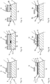
- the Figures 1a to 1c show the example of a first embodiment of a cable 1 in chronological order the steps of the method according to the invention.
- the cable 1 comprises a conductor structure 3 embodied as an inner conductor 4 and an outer cable jacket 7, with a cable foil 6, which consists of a plastic, being arranged between the inner conductor 4 and the cable jacket 7.
- the cable film 6 is accordingly on the as Inner conductor 4 formed conductor structure 3 applied.
- the cable 1 also has a cable axis 2, which represents an axis of symmetry for the cable structure.
- an end section 1b of the cable 1 in which a section 6a of the cable foil 6 to be removed is to be removed from the inner conductor 4 in order to expose a section of the inner conductor 4 .
- the end section 1b of the cable 1 is arranged in sections within an induction coil 12 in order to be able to carry out the inductive heat treatment described below.
- Figure 1b shows the end section 1b during or immediately after the inductive heat treatment by means of the induction coil 12.
- the induction coil 12 heats the inner conductor 4, ie the conductor structure 3 on which the cable foil 6 is applied, inductively. Due to the heating of the inner conductor 4 in a defined area, the cable foil 6 is thermally damaged in a correspondingly defined damage area S.
- the thermal damage can be, for example, a local melting, fusing or melting of the plastic of the cable foil 6 in the damage area S, especially if it is a thermoplastic material. It is also conceivable that the plastic of the cable foil 6 in the damage area S is burned off, degraded or embrittled by the thermal damage, in particular if it is a non-thermoplastic plastic.
- an area is defined in which a movement of the cable foil 6 relative to the inner conductor 4 forms a tear which divides the cable foil 6 into a section 6a to be removed and into a remaining section 6b.
- the section 6a of the cable foil 6 to be removed can be removed from the underlying conductor structure 3, namely the inner conductor 4, if possible without residues of the cable foil 6 remaining in the area of the inner conductor 4 to be exposed.
- the end section 1b is delimited at one end by a cable end 1a, ie an end face of the cable 1.
- the end of the end section 1b opposite the cable end can coincide with the incision 9 and/or the damage area S or can also comprise a section of the cable 1 in which the remaining section 7a of the cable jacket 7 is arranged.
- the incision 9 in the cable jacket 7 is arranged closer to the cable end 1a than the damage area S, so that the cable jacket 7 is intact in that section of the cable 1 that is inside the induction coil 12 during the inductive heat treatment. Since the heat treatment takes place inductively, the damaged area S can be produced without the cable jacket 7 having to be removed in the area to be processed beforehand. By offsetting the incision 9 and the damage area S, it is also possible to ensure that any residues of the cable foil 6 that remain on the inner conductor when it is removed are covered by the cable jacket 7, so that the stripped area of the inner conductor 4 is in any case free of plastic residues that would impede contact.
- the cable 1 is shown during a pull-off movement of the cable foil 6, with a crack having already formed in the damage area S, which has expanded or enlarged as a result of the pull-off, i.e. the movement of the cable foil 6 in the direction of the cable end 1a.
- the Cable foil 6 usually adheres to the cable sheath 7 or the adhesion between cable sheath 7 and cable foil 6 is greater than between cable foil 6 and the underlying conductor structure 3, here on the inner conductor 4. Accordingly, the section 7a of the cable sheath 7 to be removed and the removing portion 6a of the cable foil 6 is removed together by a common relative movement. This also makes it easier to grip the cable foil 6, since the cable sheath 7 can be gripped and moved using a suitable removal tool.
- the relative movement that leads to the formation of the crack does not (exclusively) necessarily have to be a translatory movement, but that a rotary movement or buckling are also conceivable.
- the sections 6a, 7a to be removed from the cable foil 6 and the cable jacket 7 are removed after the crack has formed, preferably by means of a translatory pull-off movement in the direction of the cable end 1a.
- the cable 1 in the first exemplary embodiment comprises only a single conductor structure 3, namely the inner conductor 4
- the cable 1 in the second exemplary embodiment has an inner conductor 4 and an outer conductor structure 5, namely a metal mesh 5a designed as a braided shield.
- the cable foil 6 is not applied directly to the inner conductor 4, but to the outer conductor structure 5, ie the metal mesh 5a.
- an inner insulating layer 8 is arranged between inner conductor 4 and metal mesh 5a.
- the penetration depth can be selected by means of the induction coil 12 by appropriate selection of the induction parameters, such as amplitude and frequency of the induction current, so that the metal mesh 5a in particular is heated in the damage area S, so that the cable foil 6 located on the metal mesh 5a in the damage area S is thermally damaged. It is particularly advantageous if the insulation layer 8 has a higher thermal resistance than the cable foil 6 in order to prevent the insulation layer 8 in the damage area S from being significantly thermally damaged.
- the cable 1 has three conductor structures 3, namely an inner conductor 4 and two outer conductor structures 5 on.
- the first outer conductor structure 5a is a metal mesh 5a designed as a braided shield, which is applied to an insulating layer 8 .
- a second outer conductor structure in the form of a metal foil 5b is located on the metal mesh 5a.
- the cable foil 6 is applied to the metal foil 5b, it also being conceivable for the metal foil 5b and the cable foil 6 to be in the form of a composite foil.
- This cable structure is a typical cable structure of a coaxial cable, in which the metal mesh 5a acts as a shield mesh.
- Figure 3b shows that the incision 9 can be made before, after or during the inductive heating of the metal foil 5b by means of the induction coil 12, but in the same processing device 10 (see FIG Figures 4 to 6 ).
- the penetration depth can be selected by appropriate selection of the induction parameters, such as amplitude and frequency of the induction current, so that the metal foil 5b in particular is heated in the damage area S, so that the cable foil 6 located on the metal foil 5b in the damage area S is thermally damaged.
- the metal mesh 5a is exposed by removing the sections 6a, 7a of the cable foil 6 and the cable sheath 7 that are to be removed.
- a tear also forms in the metal foil 5b in the damage area S, so that the metal foil 5b, together with the cable jacket 7 and cable foil 6 can be peeled off from the portion of the end portion 1b of the cable 1 to be exposed.
- the joint removal can be achieved particularly easily with a composite foil, but it is also conceivable that the thermal damage to the cable foil 6 reduces the tensile resistance of the metal foil 5b in such a way that during the relative movement due to the high adhesion between the cable foil 6 and metal foil 5b a crack forms in the metal foil 5b.
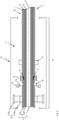
- Processing device 10 shown is intended to illustrate the functioning of the method according to the invention.
- the processing device 10 delimits a processing space 11, in which processing space 11 an end section 1b of a cable 1 to be processed is accommodated, and has at least one passage opening 16 for inserting the end section 1b.
- the structure of the cable 1 corresponds to that in connection with the Figures 3a to 3c described structure, so that the cable 1 comprises an inner conductor 4, an insulation layer 8, a metal mesh 5a designed as a braided shield and a metal foil 5b, a plastic foil 6 applied to the metal foil 5b and a cable jacket 7 in the order given below.
- the induction coil 12 is arranged in the processing space 11 with the end portion 1b passing through the induction coil 12 is, so that at least that area of the cable 1 in which the damage area S is to be generated is arranged within the induction coil 12 . Furthermore, to fix the end section 1b of the cable 1, at least one clamping unit 15 is provided in the processing space 11, by means of which the end section 1b can be clamped during processing.
- the clamping unit 15 preferably comprises one or more clamping elements made of plastic so that they can be positioned in the vicinity of the induction coil 12 .
- the processing device 10 also includes a cutting unit 14 with at least one cutting element 14a for making an incision 9 in the cable jacket 7 and means 13 for pulling off the section 6a of the cable foil 6 to be removed.
- the means 13 for pulling off include a gripping element 13a, which is designed to grip the cable sheath 7 or the cable foil 6, and a movement device 13b, by means of which the gripping elements 13a as soon as they grip the cable sheath 7 or the cable foil 6 have moved relative to the cable 1, preferably can be shifted or twisted.
- the end figure 4 shows the first step of the method, namely the provision of an end section 1b of a cable 1, which has at least one conductor structure 3 and in which a cable film 6 made of plastic is applied to one of the conductor structures 3.
- the clamping unit 15 is already in a state that is clamping the remaining section 7b of the cable sheath 7, and the gripping elements 13a are in engagement with the section 7a of the cable sheath 7 that is to be removed.
- the induction coil 12 is in relation to the cable axis 2 between the means 13 for peeling off the cable foil 6 and the clamping unit 15 in order to fix the section of the cable 1 to be processed.
- figure 5 now shows the step of generating the defined damage area S by that conductor structure 3, im present, the metal foil 5b, which is in contact with the cable foil 6, is inductively heated by means of the induction coil 12, so that the cable foil 6 is thermally damaged in the damage area S.
- the geometry of the induction coil 12, which is preferably water-cooled, and the induction parameters, such as amplitude and frequency as well as the heating duration, are selected in such a way that an electromagnetic alternating field is generated in the induction coil 12 Penetration depth a maximum heating of the metal foil 5b is reached.
- the cable foil 6 Since the metal foil 5b withstands a significantly higher thermal load than the plastic cable foil 6 applied to it due to the material properties, the cable foil 6 is thermally damaged in the damage area S by the inductive heating of the metal foil 5b, for example melted or embrittled or degraded. In order to achieve such thermal damage, the cable foil 6 is brought to a temperature of between 120° C. and 200° C. in the damage area S by means of the inductively heated metal foil 5b. The duration of the inductive heating is advantageously less than 20 s, preferably less than 10 s.
- the metal foil 5b is designed to be structurally weakened by the inductive heating, so that a defined formation of cracks in the metal foil 5b in the damage region S is achieved.
- the cable jacket 7 can be completely intact during the heating, since the alternating electromagnetic field can penetrate the cable jacket 7 without this leading to heating or being impeded by the cable jacket 7 .
- End sections 1b of cables 1 with different diameters and cable structures can also be processed by means of an induction coil 12, since only the parameters of the alternating electromagnetic field have to be set accordingly.
- the end section 1b is shown after the creation of an incision 9 in the cable jacket 7 by means of the cutting unit 14.
- the cutting elements 14a penetrate in the radial direction into the cable jacket 7, the cutting elements 14a being designed to produce an at least partially, preferably completely, circumferential incision 9.
- the portion 7a of the cable sheath 7 to be removed can be pushed toward the cable end 1a by the cutting unit 14 to enlarge the incision 9 in the axial direction.
- the cutting unit 14 is arranged between the means 13 for pulling off the cable foil 6, in particular between the gripping elements 13a, and the induction coil 12, so that the section between the incision 9 and the cable end 1a is less than the distance between the cable end 1a and the induction coil 12 Seen from the passage opening 16 , the induction coil 12 is positioned between the passage opening 16 and the cutting unit 14 .
- Appropriate positioning of the cutting unit 14 ensures that any remnants of the cable foil 6 remaining in the damage area S during the subsequent relative movement and removal are covered by the remaining section 7b of the cable sheath 7 and thus do not adversely affect contacting of the metal mesh 5a.
- the described positioning of the cutting unit 14 ensures that the cable sheath 7 is intact in that area of the cable 1 in which the damage area S is generated by the induction coil 12 is.
- the cutting unit 14 is not necessarily a required part of the Processing device 10, since the incision 9 can also be made before the insertion of the end section 1b into the processing space 11 or the cable sheath 7 can be removed in the section to be processed before insertion.
- FIG 7 the step of moving the cable foil 6 relative to the conductor structures 3 remaining on the cable 1, namely relative to the inner conductor 4 and the metal mesh 5a, is shown. Due to the relative movement, which can be a translational movement, a twisting movement or a buckling movement, a tear forms in the cable foil 6 in the damage area S, which tear separates the section 6a to be removed and the remaining section 6b of the cable foil 6 from one another . Furthermore, a crack also forms in the metal foil 5b in the damage area S, so that the metal foil 5b can then also be removed together with the sections 6a, 7a of cable foil 6 and cable jacket 7 to be removed in order to expose the metal mesh 5a for contacting.
- the relative movement which can be a translational movement, a twisting movement or a buckling movement
- a tear forms in the cable foil 6 in the damage area S, which tear separates the section 6a to be removed and the remaining section 6b of the cable foil 6 from one another .
- a crack also forms in the
- the movement of the gripping elements 13a which clamp the section 7a of the cable sheath 7 to be removed, also clamps the section 6a to be removed of the cable foil 6 adhering to the cable sheath 7 and the metal foil 5b adhering to the cable foil 6, in particular if the cable foil 6 and Metal foil 5b are formed as a composite film, moved relative to the metal mesh 5a to form the crack.
- the crack will form as a result of the thermal damage to the cable foil 6 .
- the removing sections 6a, 7a of the cable foil 6 and cable jacket 7 and of the metal foil 5b can be completely removed from the cable in a simple manner, preferably by the means 13 for pulling 1 be deducted in order to expose the metal braiding 5a designed as a braided shield.
- processing device 10 described above can be used to process cables with cable structures that are shown in the exemplary embodiments described in detail above, as well as cables with cable structures that have one or more intermediate layers.
- the cutting unit 14 can be arranged in a further processing space of a cutting device of the processing device 10 and/or the means 13 for removing the cable foil 6 can be arranged in a further processing space of a stripping device of the processing device 10, while the induction coil 12 and preferably the clamping unit 15 are in the processing space 11 is arranged.
Landscapes
- Physics & Mathematics (AREA)
- Optics & Photonics (AREA)
- Engineering & Computer Science (AREA)
- Manufacturing & Machinery (AREA)
- Processing Of Terminals (AREA)
- Removal Of Insulation Or Armoring From Wires Or Cables (AREA)
- Insulated Conductors (AREA)
- Details Of Cutting Devices (AREA)
Claims (13)
- Procédé pour enlever une section à enlever (6a) d'une feuille de câble (6) d'une section terminale (1b) d'un câble (1),
comprenant les étapes suivantes :- la fourniture d'une section terminale (1b) d'un câble (1) présentant un axe de câble (2), le câble (1) comprenant une gaine de câble (7) ainsi qu'au moins une structure conductrice d'électricité (3, 4, 5) et la feuille de câble (6) en plastique disposée sur une des structures conductrices (3, 4, 5) ;- la génération d'une zone de dommage (S) définie dans la section terminale (1b) fournie du câble (1), dans laquelle au moins chaque structure conductrice (3, 4, 5a, 5b), sur laquelle est disposée la feuille de câble (6), est chauffée par induction de telle sorte que la feuille de câble (6) disposée sur la structure conductrice chauffée (3, 4, 5a, 5b) est endommagée thermiquement au moins partiellement dans la zone de dommage (S),la feuille de câble (6) étant recouverte par la gaine de câble (7) dans la zone de dommage (S) pendant le chauffage par induction de l'au moins une structure (3, 4, 5),- la coupe au moins partiellement circonférentielle de la gaine de câble (7) pendant ou après la génération de la zone de dommage (S), la coupe au moins partiellement circonférentielle s'effectuant sur une position qui est disposée plus près d'une extrémité de câble (1a) de la section terminale (1b) que la zone de dommage (S) ;- le mouvement de la feuille de câble (6) relativement à une des structures conductrices (3, 4, 5), une fissure se formant dans la zone de dommage (S) en raison du mouvement relatif, fissure qui sépare la section à enlever (6a) de la feuille de câble (6) d'une section (6b) restée sur le câble (1) de la feuille de câble (6). - Procédé pour enlever une section à enlever (6a) d'une feuille de câble (6) d'une section terminale (1b) d'un câble (1),
comprenant les étapes suivantes :- la fourniture d'une section terminale (1b) d'un câble (1) présentant un axe de câble (2), le câble (1) comprenant une gaine de câble (7) ainsi qu'au moins une structure conductrice d'électricité (3, 4, 5) et la feuille de câble (6) en plastique disposée sur une des structures conductrices (3, 4, 5) ;- la production d'une entaille (9) dans la section terminale (1b) fournie du câble (1) après la coupe au moins partiellement circonférentielle de la gaine de câble (7) ;- la génération d'une zone de dommage (S) définie dans la section terminale (1b) du câble (1), dans laquelle au moins la structure conductrice (3, 4, 5a, 5b), sur laquelle est disposée la feuille de câble (6), est chauffée par induction de telle sorte que la feuille de câble (6) disposée sur la structure conductrice chauffée (3, 4, 5a, 5b) est endommagée thermiquement au moins partiellement dans la zone de dommage (S),la zone de dommage (S) étant générée après la production de l'entaille (9),un écart entre une extrémité de câble (1a) de la section terminale (1b) et la zone de dommage (S) étant plus grand qu'entre l'extrémité de câble (1a) et une position de l'entaille (9),la feuille de câble (6) étant recouverte par la gaine de câble (7) dans la zone de dommage (S) pendant le chauffage par induction de l'au moins une structure conductrice (3, 4, 5) ;- le mouvement de la feuille de câble (6) relativement à une des structures conductrices (3, 4, 5), une fissure se formant dans la zone de dommage (S) en raison du mouvement relatif, fissure qui sépare la section à enlever (6a) de la feuille de câble (6) d'une section (6b) restée sur le câble (1) de la feuille de câble (6). - Procédé selon la revendication 1 ou 2, dans lequel l'au moins une structure conductrice (3) se compose d'un conducteur intérieur (4) et d'au moins une structure conductrice (5, 5a, 5b) extérieure, la feuille de câble (6) étant disposée sur une des structures conductrices (5, 5a, 5b) extérieures.
- Procédé selon la revendication 3, dans lequel chaque structure conductrice extérieure (5), sur laquelle est disposé la feuille de câble (6), est configurée comme une feuille métallique (5b).
- Procédé selon la revendication 4, dans lequel la structure conductrice (5) extérieure configurée comme une feuille métallique (5b) est affaiblie structurellement en raison du chauffage par induction dans la zone de dommage (S).
- Procédé selon l'une quelconque des revendications 1 à 5, dans lequel le chauffage par induction s'effectue au moyen d'une bobine d'induction (12), au moyen de laquelle (12) un champ alternatif électromagnétique est généré, au moins la zone de dommage (S) du câble (1) étant disposée à l'intérieur de la bobine d'induction (12) pendant le chauffage par induction.
- Procédé selon l'une quelconque des revendications 1 à 6, dans lequel la gaine de câble (7) est divisée par une entaille (9) produite au moyen de l'étape de la coupe au moins partiellement circonférentielle dans une section à enlever (7a) de la gaine de câble (7) et une section restante (7b) de la gaine de câble (7) et en ce que la section à enlever (7a) de la gaine de câble (7) est déplacée dans la direction de l'axe de câble (2), la section à enlever (6a) de la feuille de câble (6) adhérant au moins partiellement à la gaine de câble (7) étant retirée en raison du mouvement.
- Procédé selon l'une quelconque des revendications 1 à 7, dans lequel les étapes- chauffage par induction au moins de la structure conductrice (3, 4, 5a, 5b) sur laquelle la feuille de câble (6) est déposée ;- la coupe au moins partiellement circonférentielle de la gaine de câble (7) ;- l'enlèvement commun d'une section à enlever (7a) de la gaine de câble (7) et de la section à enlever (6a) de la feuille de câble (6) sont réalisées dans l'espace d'usinage (11) d'un dispositif d'usinage (10).
- Procédé selon l'une quelconque des revendications 1 à 8, dans lequel l'au moins une structure conductrice (3, 4, 5), sur laquelle la feuille de câble (6) est déposée, est chauffée par induction à une température égale ou supérieure à 80 °C, de préférence égale ou supérieure à 100 °C, mieux encore égale ou supérieure à 200 °C, notamment égale ou supérieure à 300 °C.
- Dispositif d'usinage (10) pour la mise en œuvre d'un procédé selon l'une quelconque des revendications 1 à 9 comprenant :- un espace d'usinage (11) pour la réception d'une section terminale (1b) d'un câble à usiner (1), le câble (1) comprenant une gaine de câble (7) ainsi qu'au moins une structure conductrice d'électricité (3, 4, 5) et une feuille de câble (6) en plastique disposée sur une des structures conductrices (3, 4, 5),l'espace d'usinage (11) présentant une ouverture de passage (16) pour le câble (1) ;- une bobine à induction (12) disposée dans l'espace d'usinage (11) ;- un moyen (13) pour retirer une section à enlever (6a) de la feuille de câble (6) définie par une zone de dommage (S) ;- une unité de coupe (14) pour la coupe au moins partiellement circonférentielle de la gaine de câble (7),caractérisé en ce quela bobine à induction (12) est conçue pour générer un champ alternatif électromagnétique afin de chauffer par induction au moins la structure conductrice (3, 4, 5a, 5b) d'une section du câble (1) se trouvant dans la bobine à induction (12) pendant une opération d'usinage, structure conductrice (3, 4, 5a, 5b) sur laquelle est disposée la feuille de câble (6), de telle sorte que la feuille de câble (6) disposée sur la structure conductrice (3, 4, 5a, 5b) chauffée est endommagée thermiquement au moins partiellement dans la zone de dommage (S) ;et en ce quel'unité de coupe (14) est disposée dans l'espace d'usinage (11), la bobine à induction (12) étant disposée entre l'unité de coupe (14) et l'ouverture de passage (16), et l'unité de coupe (14) est conçue pour couper la gaine de câble (7) à une position qui est située plus près sur l'extrémité de câble (1a) de la section terminale (1b) que la zone de dommage (S).
- Dispositif d'usinage (10) selon la revendication 10, caractérisé en ce qu'au moins une unité de serrage (15) pour fixer la section terminale (1b) du câble (1) pendant une opération d'usinage est disposée dans l'espace d'usinage (11).
- Dispositif d'usinage (10) selon l'une quelconque des revendications 10 à 11, caractérisé en ce que les moyens (13) pour retirer la section à enlever (6a) de la feuille de câble (6) sont configurés pour toucher une section à enlever (7a) de la gaine de câble (7) définie par une entaille (9) puis pour enlever par un mouvement de retrait la section à enlever (7a) de la gaine de câble (7) avec une section à enlever (6a) de la feuille de câble (6a).
- Dispositif d'usinage (10) selon l'une quelconque des revendications 10 à 12, caractérisé en ce que les moyens (13) pour retirer la section à enlever (6a) de la feuille de câble (6) sont disposés dans l'espace d'usinage (11).
Priority Applications (11)
| Application Number | Priority Date | Filing Date | Title |
|---|---|---|---|
| EP19207945.7A EP3820006B1 (fr) | 2019-11-08 | 2019-11-08 | Procédé d'enlèvement d'une feuille pour câble |
| CN202080031679.4A CN113785455B (zh) | 2019-11-08 | 2020-11-05 | 用于去除线缆箔的方法以及加工设备 |
| JP2022521442A JP7657787B2 (ja) | 2019-11-08 | 2020-11-05 | ケーブル箔を除去する方法 |
| KR1020227018384A KR102961978B1 (ko) | 2019-11-08 | 2020-11-05 | 케이블 박막의 제거 방법 |
| DE112020005497.7T DE112020005497A5 (de) | 2019-11-08 | 2020-11-05 | Verfahren zum Entfernen einer Kabelfolie |
| PCT/EP2020/081210 WO2021089744A1 (fr) | 2019-11-08 | 2020-11-05 | Procédé de retrait d'un film de câble |
| DE202020005834.3U DE202020005834U1 (de) | 2019-11-08 | 2020-11-05 | Bearbeitungsvorrichtung zum Entfernen einer Kabelfolie |
| DE202020005837.8U DE202020005837U1 (de) | 2019-11-08 | 2020-11-05 | Bearbeitungsvorrichtung zum Entfernen einer Kabelfolie |
| US17/755,752 US20220393445A1 (en) | 2019-11-08 | 2020-11-05 | Method For Removing A Cable Film |
| MX2022005426A MX2022005426A (es) | 2019-11-08 | 2020-11-05 | Procedimiento para retirar la pelicula de un cable. |
| US19/427,631 US20260112869A1 (en) | 2019-11-08 | 2025-12-19 | Method for removing a cable film |
Applications Claiming Priority (1)
| Application Number | Priority Date | Filing Date | Title |
|---|---|---|---|
| EP19207945.7A EP3820006B1 (fr) | 2019-11-08 | 2019-11-08 | Procédé d'enlèvement d'une feuille pour câble |
Publications (2)
| Publication Number | Publication Date |
|---|---|
| EP3820006A1 EP3820006A1 (fr) | 2021-05-12 |
| EP3820006B1 true EP3820006B1 (fr) | 2022-03-02 |
Family
ID=68501397
Family Applications (1)
| Application Number | Title | Priority Date | Filing Date |
|---|---|---|---|
| EP19207945.7A Active EP3820006B1 (fr) | 2019-11-08 | 2019-11-08 | Procédé d'enlèvement d'une feuille pour câble |
Country Status (7)
| Country | Link |
|---|---|
| US (2) | US20220393445A1 (fr) |
| EP (1) | EP3820006B1 (fr) |
| JP (1) | JP7657787B2 (fr) |
| CN (1) | CN113785455B (fr) |
| DE (3) | DE202020005837U1 (fr) |
| MX (1) | MX2022005426A (fr) |
| WO (1) | WO2021089744A1 (fr) |
Families Citing this family (2)
| Publication number | Priority date | Publication date | Assignee | Title |
|---|---|---|---|---|
| US12088029B2 (en) * | 2021-07-20 | 2024-09-10 | Dell Products L.P. | Cable termination for information handling systems |
| DE202023002310U1 (de) | 2023-06-15 | 2024-06-25 | Feintechnik R. Rittmeyer Gmbh | Vorrichtung zur partiellen Erwärmung von linearen Medien mit metallischen Anteilen mittels magnetischen Wechselfeld |
Citations (1)
| Publication number | Priority date | Publication date | Assignee | Title |
|---|---|---|---|---|
| WO2020188456A1 (fr) * | 2019-03-20 | 2020-09-24 | Te Connectivity Corporation | Procédé d'élimination de protection en feuille d'un câble |
Family Cites Families (16)
| Publication number | Priority date | Publication date | Assignee | Title |
|---|---|---|---|---|
| US3765276A (en) * | 1972-03-24 | 1973-10-16 | Western Electric Co | Wire stripper device |
| JP2951359B2 (ja) * | 1989-04-20 | 1999-09-20 | 古河電気工業株式会社 | 光ファイバ用被覆除去装置 |
| JPH0710141B2 (ja) * | 1989-09-21 | 1995-02-01 | 株式会社日立製作所 | ケーブルの端末処理方法およびその端末処理装置 |
| DE4036011C2 (de) * | 1990-11-13 | 1993-11-25 | Horst Schlauteck | Vorrichtung zum Durchtrennen einer metallischen Abschirmung |
| JPH11332050A (ja) * | 1998-05-08 | 1999-11-30 | Miyaden:Kk | リード端末処理方法及びその処理装置 |
| JP4091348B2 (ja) * | 2002-06-10 | 2008-05-28 | 矢崎総業株式会社 | フラットシールド電線のシールド処理構造及びそのシールド処理方法 |
| US9511536B2 (en) * | 2002-10-18 | 2016-12-06 | The Boeing Company | Method and apparatus to assist with removing an adhesive system |
| DE102011004078B4 (de) * | 2011-02-14 | 2012-10-31 | Aloys Wobben | Vorrichtung und Verfahren zum induktiven Abisolieren von Drähten und/oder Profilen |
| US9318884B2 (en) * | 2011-03-30 | 2016-04-19 | Illinois Tool Works Inc. | Induction heating wire insulation heating and removal |
| RS61248B1 (sr) * | 2016-10-18 | 2021-01-29 | Komax Holding Ag | Postupak i uređaj za skidanje izolacije kabla sa višeslojnom oblogom |
| EP3322054B1 (fr) * | 2016-11-15 | 2020-06-03 | Schleuniger Holding AG | Dispositif et procédé destinés à enlever une gaine intérieure de conducteur électrique |
| JP6353586B1 (ja) * | 2017-06-01 | 2018-07-04 | 株式会社岩崎電機製作所 | ケーブル被覆体のストリップ装置 |
| DE102017118445A1 (de) | 2017-08-14 | 2019-02-14 | Metzner Maschinenbau Gmbh | Verfahren und Vorrichtung zum Entfernen einer Kabelfolie |
| EP3447865B1 (fr) * | 2017-08-23 | 2022-10-05 | Komax Holding Ag | Procédé d'enlèvement d'une partie d'une feuille écran d'un habillage de câble de ligne et dispositif d'enlèvement des feuilles permettant l'enlèvement d'une partie d'une feuille écran d'un habillage de câble de ligne à un point de rupture de l'habillage de câble de ligne |
| CN207765892U (zh) * | 2017-11-13 | 2018-08-24 | 胡朝海 | 一种高效率电气工程用剥线装置 |
| DE102017221115B3 (de) * | 2017-11-27 | 2019-01-31 | Leoni Kabel Gmbh | Verfahren sowie Vorrichtung zum Abisolieren einer Leitung |
-
2019
- 2019-11-08 EP EP19207945.7A patent/EP3820006B1/fr active Active
-
2020
- 2020-11-05 CN CN202080031679.4A patent/CN113785455B/zh active Active
- 2020-11-05 DE DE202020005837.8U patent/DE202020005837U1/de active Active
- 2020-11-05 US US17/755,752 patent/US20220393445A1/en active Pending
- 2020-11-05 DE DE112020005497.7T patent/DE112020005497A5/de active Pending
- 2020-11-05 JP JP2022521442A patent/JP7657787B2/ja active Active
- 2020-11-05 WO PCT/EP2020/081210 patent/WO2021089744A1/fr not_active Ceased
- 2020-11-05 DE DE202020005834.3U patent/DE202020005834U1/de active Active
- 2020-11-05 MX MX2022005426A patent/MX2022005426A/es unknown
-
2025
- 2025-12-19 US US19/427,631 patent/US20260112869A1/en active Pending
Patent Citations (1)
| Publication number | Priority date | Publication date | Assignee | Title |
|---|---|---|---|---|
| WO2020188456A1 (fr) * | 2019-03-20 | 2020-09-24 | Te Connectivity Corporation | Procédé d'élimination de protection en feuille d'un câble |
Also Published As
| Publication number | Publication date |
|---|---|
| DE202020005837U1 (de) | 2022-12-06 |
| JP2023500036A (ja) | 2023-01-04 |
| EP3820006A1 (fr) | 2021-05-12 |
| CN113785455B (zh) | 2023-03-07 |
| DE202020005834U1 (de) | 2022-12-05 |
| US20260112869A1 (en) | 2026-04-23 |
| CN113785455A (zh) | 2021-12-10 |
| MX2022005426A (es) | 2022-08-04 |
| US20220393445A1 (en) | 2022-12-08 |
| JP7657787B2 (ja) | 2025-04-07 |
| WO2021089744A1 (fr) | 2021-05-14 |
| DE112020005497A5 (de) | 2022-09-15 |
| KR20220122981A (ko) | 2022-09-05 |
Similar Documents
| Publication | Publication Date | Title |
|---|---|---|
| EP2912736B1 (fr) | Dispositif et procedure de preparation de la partie terminale d'un cable | |
| EP3925041B1 (fr) | Procédé et dispositif permettant de produire un câble électrique | |
| EP4092850B1 (fr) | Procédé et dispositif d'enlèvement d'une feuille de câble | |
| DE102017221115B3 (de) | Verfahren sowie Vorrichtung zum Abisolieren einer Leitung | |
| EP3312956B1 (fr) | Procédé et dispositif pour dénuder un câble comprenant une gaine multicouches | |
| EP2887475B1 (fr) | Procédé et dispositif de séparation d'un blindage d'un câble coaxial | |
| EP3820006B1 (fr) | Procédé d'enlèvement d'une feuille pour câble | |
| DE102015112320B3 (de) | Vorrichtung und Verfahren zum Abisolieren von Leitungen oder Kabeln | |
| DE2841143A1 (de) | Verfahren zur herstellung einer elektrischen verbindung sowie verbindungsteil, verbindungssatz und abstandshalter zur durchfuehrung des verfahrens | |
| EP3952035B1 (fr) | Procédé et dispositif d'usinage d'une extrémité de câble, ainsi que câble ainsi usiné | |
| DE102013105678B4 (de) | Verfahren zum Trennen von Wickelschläuchen | |
| EP4055674B1 (fr) | Procédé et dispositif de traitement d'un câble électrique | |
| EP3804048B1 (fr) | Dispositif et procédé servant à usiner une extrémité d'un câble électrique | |
| EP3824521B1 (fr) | Dispositif et procédé de traitement d'une extrémité d'un câble électrique | |
| EP2274797B1 (fr) | Cable electrique ainsi que procede et dispositif pour sa production | |
| DE102017215970B3 (de) | Verfahren zum Verbinden einer elektrischen Aluminiumleitung mit einem Aluminiumrohr | |
| EP3925040B1 (fr) | Procédé et dispositif pour retirer une feuille de câble | |
| EP3238871B1 (fr) | Procédé de fabrication d'un tube en métal uilisant le soudage par laser | |
| DE102020123696A1 (de) | Verfahren zum abmanteln eines kabels und vorrichtung hierfür | |
| DE19958763C1 (de) | Verfahren zum Bearbeiten von mineral-isolierten Leitungen | |
| DE202022001574U1 (de) | Vorrichtung zur Vorschädigung von Trennhilfen oder Teilen davon aus thermoplastischem Gewebe und deren Entfernung von elektrischen Leitern | |
| EP2410612A1 (fr) | Procédé destiné à la fabrication de câbles comprenants de conducteurs en aluminium | |
| EP3192394B1 (fr) | Procédé de production d'un joint-brosse d'étanchéité comprenant des soies obliques | |
| DE202020003741U1 (de) | Vorrichtung zur Vorschädigung von Verbund-Schirmfolien und deren Entfernung von elektrischen Leitungen | |
| DE102006026502A1 (de) | Verfahren zum Herstellen einer elektrisch leitenden Kontaktierung zu einem Außenleiter eines mit einer Isolierung versehenen Koaxialkabels |
Legal Events
| Date | Code | Title | Description |
|---|---|---|---|
| STAA | Information on the status of an ep patent application or granted ep patent |
Free format text: STATUS: EXAMINATION IS IN PROGRESS |
|
| PUAI | Public reference made under article 153(3) epc to a published international application that has entered the european phase |
Free format text: ORIGINAL CODE: 0009012 |
|
| 17P | Request for examination filed |
Effective date: 20200804 |
|
| AK | Designated contracting states |
Kind code of ref document: A1 Designated state(s): AL AT BE BG CH CY CZ DE DK EE ES FI FR GB GR HR HU IE IS IT LI LT LU LV MC MK MT NL NO PL PT RO RS SE SI SK SM TR |
|
| GRAP | Despatch of communication of intention to grant a patent |
Free format text: ORIGINAL CODE: EPIDOSNIGR1 |
|
| STAA | Information on the status of an ep patent application or granted ep patent |
Free format text: STATUS: GRANT OF PATENT IS INTENDED |
|
| INTG | Intention to grant announced |
Effective date: 20211112 |
|
| GRAS | Grant fee paid |
Free format text: ORIGINAL CODE: EPIDOSNIGR3 |
|
| GRAA | (expected) grant |
Free format text: ORIGINAL CODE: 0009210 |
|
| STAA | Information on the status of an ep patent application or granted ep patent |
Free format text: STATUS: THE PATENT HAS BEEN GRANTED |
|
| AK | Designated contracting states |
Kind code of ref document: B1 Designated state(s): AL AT BE BG CH CY CZ DE DK EE ES FI FR GB GR HR HU IE IS IT LI LT LU LV MC MK MT NL NO PL PT RO RS SE SI SK SM TR |
|
| REG | Reference to a national code |
Ref country code: GB Ref legal event code: FG4D Free format text: NOT ENGLISH |
|
| REG | Reference to a national code |
Ref country code: CH Ref legal event code: EP Ref country code: AT Ref legal event code: REF Ref document number: 1473033 Country of ref document: AT Kind code of ref document: T Effective date: 20220315 |
|
| REG | Reference to a national code |
Ref country code: DE Ref legal event code: R096 Ref document number: 502019003549 Country of ref document: DE |
|
| REG | Reference to a national code |
Ref country code: IE Ref legal event code: FG4D Free format text: LANGUAGE OF EP DOCUMENT: GERMAN |
|
| REG | Reference to a national code |
Ref country code: LT Ref legal event code: MG9D |
|
| REG | Reference to a national code |
Ref country code: NL Ref legal event code: MP Effective date: 20220302 |
|
| PG25 | Lapsed in a contracting state [announced via postgrant information from national office to epo] |
Ref country code: SE Free format text: LAPSE BECAUSE OF FAILURE TO SUBMIT A TRANSLATION OF THE DESCRIPTION OR TO PAY THE FEE WITHIN THE PRESCRIBED TIME-LIMIT Effective date: 20220302 Ref country code: RS Free format text: LAPSE BECAUSE OF FAILURE TO SUBMIT A TRANSLATION OF THE DESCRIPTION OR TO PAY THE FEE WITHIN THE PRESCRIBED TIME-LIMIT Effective date: 20220302 Ref country code: NO Free format text: LAPSE BECAUSE OF FAILURE TO SUBMIT A TRANSLATION OF THE DESCRIPTION OR TO PAY THE FEE WITHIN THE PRESCRIBED TIME-LIMIT Effective date: 20220602 Ref country code: LT Free format text: LAPSE BECAUSE OF FAILURE TO SUBMIT A TRANSLATION OF THE DESCRIPTION OR TO PAY THE FEE WITHIN THE PRESCRIBED TIME-LIMIT Effective date: 20220302 Ref country code: HR Free format text: LAPSE BECAUSE OF FAILURE TO SUBMIT A TRANSLATION OF THE DESCRIPTION OR TO PAY THE FEE WITHIN THE PRESCRIBED TIME-LIMIT Effective date: 20220302 Ref country code: ES Free format text: LAPSE BECAUSE OF FAILURE TO SUBMIT A TRANSLATION OF THE DESCRIPTION OR TO PAY THE FEE WITHIN THE PRESCRIBED TIME-LIMIT Effective date: 20220302 Ref country code: BG Free format text: LAPSE BECAUSE OF FAILURE TO SUBMIT A TRANSLATION OF THE DESCRIPTION OR TO PAY THE FEE WITHIN THE PRESCRIBED TIME-LIMIT Effective date: 20220602 |
|
| PG25 | Lapsed in a contracting state [announced via postgrant information from national office to epo] |
Ref country code: PL Free format text: LAPSE BECAUSE OF FAILURE TO SUBMIT A TRANSLATION OF THE DESCRIPTION OR TO PAY THE FEE WITHIN THE PRESCRIBED TIME-LIMIT Effective date: 20220302 Ref country code: LV Free format text: LAPSE BECAUSE OF FAILURE TO SUBMIT A TRANSLATION OF THE DESCRIPTION OR TO PAY THE FEE WITHIN THE PRESCRIBED TIME-LIMIT Effective date: 20220302 Ref country code: GR Free format text: LAPSE BECAUSE OF FAILURE TO SUBMIT A TRANSLATION OF THE DESCRIPTION OR TO PAY THE FEE WITHIN THE PRESCRIBED TIME-LIMIT Effective date: 20220603 Ref country code: FI Free format text: LAPSE BECAUSE OF FAILURE TO SUBMIT A TRANSLATION OF THE DESCRIPTION OR TO PAY THE FEE WITHIN THE PRESCRIBED TIME-LIMIT Effective date: 20220302 |
|
| PG25 | Lapsed in a contracting state [announced via postgrant information from national office to epo] |
Ref country code: NL Free format text: LAPSE BECAUSE OF FAILURE TO SUBMIT A TRANSLATION OF THE DESCRIPTION OR TO PAY THE FEE WITHIN THE PRESCRIBED TIME-LIMIT Effective date: 20220302 |
|
| PG25 | Lapsed in a contracting state [announced via postgrant information from national office to epo] |
Ref country code: SM Free format text: LAPSE BECAUSE OF FAILURE TO SUBMIT A TRANSLATION OF THE DESCRIPTION OR TO PAY THE FEE WITHIN THE PRESCRIBED TIME-LIMIT Effective date: 20220302 Ref country code: SK Free format text: LAPSE BECAUSE OF FAILURE TO SUBMIT A TRANSLATION OF THE DESCRIPTION OR TO PAY THE FEE WITHIN THE PRESCRIBED TIME-LIMIT Effective date: 20220302 Ref country code: RO Free format text: LAPSE BECAUSE OF FAILURE TO SUBMIT A TRANSLATION OF THE DESCRIPTION OR TO PAY THE FEE WITHIN THE PRESCRIBED TIME-LIMIT Effective date: 20220302 Ref country code: PT Free format text: LAPSE BECAUSE OF FAILURE TO SUBMIT A TRANSLATION OF THE DESCRIPTION OR TO PAY THE FEE WITHIN THE PRESCRIBED TIME-LIMIT Effective date: 20220704 Ref country code: EE Free format text: LAPSE BECAUSE OF FAILURE TO SUBMIT A TRANSLATION OF THE DESCRIPTION OR TO PAY THE FEE WITHIN THE PRESCRIBED TIME-LIMIT Effective date: 20220302 Ref country code: CZ Free format text: LAPSE BECAUSE OF FAILURE TO SUBMIT A TRANSLATION OF THE DESCRIPTION OR TO PAY THE FEE WITHIN THE PRESCRIBED TIME-LIMIT Effective date: 20220302 |
|
| PG25 | Lapsed in a contracting state [announced via postgrant information from national office to epo] |
Ref country code: IS Free format text: LAPSE BECAUSE OF FAILURE TO SUBMIT A TRANSLATION OF THE DESCRIPTION OR TO PAY THE FEE WITHIN THE PRESCRIBED TIME-LIMIT Effective date: 20220702 Ref country code: AL Free format text: LAPSE BECAUSE OF FAILURE TO SUBMIT A TRANSLATION OF THE DESCRIPTION OR TO PAY THE FEE WITHIN THE PRESCRIBED TIME-LIMIT Effective date: 20220302 |
|
| REG | Reference to a national code |
Ref country code: DE Ref legal event code: R097 Ref document number: 502019003549 Country of ref document: DE |
|
| PLBE | No opposition filed within time limit |
Free format text: ORIGINAL CODE: 0009261 |
|
| STAA | Information on the status of an ep patent application or granted ep patent |
Free format text: STATUS: NO OPPOSITION FILED WITHIN TIME LIMIT |
|
| PG25 | Lapsed in a contracting state [announced via postgrant information from national office to epo] |
Ref country code: DK Free format text: LAPSE BECAUSE OF FAILURE TO SUBMIT A TRANSLATION OF THE DESCRIPTION OR TO PAY THE FEE WITHIN THE PRESCRIBED TIME-LIMIT Effective date: 20220302 |
|
| 26N | No opposition filed |
Effective date: 20221205 |
|
| P01 | Opt-out of the competence of the unified patent court (upc) registered |
Effective date: 20230510 |
|
| PG25 | Lapsed in a contracting state [announced via postgrant information from national office to epo] |
Ref country code: MC Free format text: LAPSE BECAUSE OF FAILURE TO SUBMIT A TRANSLATION OF THE DESCRIPTION OR TO PAY THE FEE WITHIN THE PRESCRIBED TIME-LIMIT Effective date: 20220302 |
|
| REG | Reference to a national code |
Ref country code: CH Ref legal event code: PL |
|
| REG | Reference to a national code |
Ref country code: BE Ref legal event code: MM Effective date: 20221130 |
|
| PG25 | Lapsed in a contracting state [announced via postgrant information from national office to epo] |
Ref country code: LI Free format text: LAPSE BECAUSE OF NON-PAYMENT OF DUE FEES Effective date: 20221130 Ref country code: CH Free format text: LAPSE BECAUSE OF NON-PAYMENT OF DUE FEES Effective date: 20221130 |
|
| PG25 | Lapsed in a contracting state [announced via postgrant information from national office to epo] |
Ref country code: LU Free format text: LAPSE BECAUSE OF NON-PAYMENT OF DUE FEES Effective date: 20221108 |
|
| PG25 | Lapsed in a contracting state [announced via postgrant information from national office to epo] |
Ref country code: IE Free format text: LAPSE BECAUSE OF NON-PAYMENT OF DUE FEES Effective date: 20221108 |
|
| PG25 | Lapsed in a contracting state [announced via postgrant information from national office to epo] |
Ref country code: BE Free format text: LAPSE BECAUSE OF NON-PAYMENT OF DUE FEES Effective date: 20221130 |
|
| PG25 | Lapsed in a contracting state [announced via postgrant information from national office to epo] |
Ref country code: CY Free format text: LAPSE BECAUSE OF FAILURE TO SUBMIT A TRANSLATION OF THE DESCRIPTION OR TO PAY THE FEE WITHIN THE PRESCRIBED TIME-LIMIT Effective date: 20220302 |
|
| PG25 | Lapsed in a contracting state [announced via postgrant information from national office to epo] |
Ref country code: MK Free format text: LAPSE BECAUSE OF FAILURE TO SUBMIT A TRANSLATION OF THE DESCRIPTION OR TO PAY THE FEE WITHIN THE PRESCRIBED TIME-LIMIT Effective date: 20220302 Ref country code: HU Free format text: LAPSE BECAUSE OF FAILURE TO SUBMIT A TRANSLATION OF THE DESCRIPTION OR TO PAY THE FEE WITHIN THE PRESCRIBED TIME-LIMIT; INVALID AB INITIO Effective date: 20191108 |
|
| PG25 | Lapsed in a contracting state [announced via postgrant information from national office to epo] |
Ref country code: TR Free format text: LAPSE BECAUSE OF FAILURE TO SUBMIT A TRANSLATION OF THE DESCRIPTION OR TO PAY THE FEE WITHIN THE PRESCRIBED TIME-LIMIT Effective date: 20220302 |
|
| PG25 | Lapsed in a contracting state [announced via postgrant information from national office to epo] |
Ref country code: MT Free format text: LAPSE BECAUSE OF FAILURE TO SUBMIT A TRANSLATION OF THE DESCRIPTION OR TO PAY THE FEE WITHIN THE PRESCRIBED TIME-LIMIT Effective date: 20220302 |
|
| PGFP | Annual fee paid to national office [announced via postgrant information from national office to epo] |
Ref country code: DE Payment date: 20251126 Year of fee payment: 7 |
|
| PGFP | Annual fee paid to national office [announced via postgrant information from national office to epo] |
Ref country code: GB Payment date: 20251125 Year of fee payment: 7 |
|
| PG25 | Lapsed in a contracting state [announced via postgrant information from national office to epo] |
Ref country code: AT Free format text: LAPSE BECAUSE OF NON-PAYMENT OF DUE FEES Effective date: 20241108 |
|
| PGFP | Annual fee paid to national office [announced via postgrant information from national office to epo] |
Ref country code: IT Payment date: 20251121 Year of fee payment: 7 |
|
| PGFP | Annual fee paid to national office [announced via postgrant information from national office to epo] |
Ref country code: FR Payment date: 20251124 Year of fee payment: 7 |
|
| REG | Reference to a national code |
Ref country code: AT Ref legal event code: MM01 Ref document number: 1473033 Country of ref document: AT Kind code of ref document: T Effective date: 20241108 |
|
| PG25 | Lapsed in a contracting state [announced via postgrant information from national office to epo] |
Ref country code: SI Free format text: LAPSE BECAUSE OF FAILURE TO SUBMIT A TRANSLATION OF THE DESCRIPTION OR TO PAY THE FEE WITHIN THE PRESCRIBED TIME-LIMIT Effective date: 20220302 |
|
| PGFP | Annual fee paid to national office [announced via postgrant information from national office to epo] |
Ref country code: AT Payment date: 20260410 Year of fee payment: 5 |