EP3926122A1 - Pièce d'angle et sous-structure pour un revêtement de cheminée d'aération - Google Patents
Pièce d'angle et sous-structure pour un revêtement de cheminée d'aération Download PDFInfo
- Publication number
- EP3926122A1 EP3926122A1 EP21179624.8A EP21179624A EP3926122A1 EP 3926122 A1 EP3926122 A1 EP 3926122A1 EP 21179624 A EP21179624 A EP 21179624A EP 3926122 A1 EP3926122 A1 EP 3926122A1
- Authority
- EP
- European Patent Office
- Prior art keywords
- angle piece
- lock
- chimney
- gear
- leg
- Prior art date
- Legal status (The legal status is an assumption and is not a legal conclusion. Google has not performed a legal analysis and makes no representation as to the accuracy of the status listed.)
- Granted
Links
Images


Classifications
-
- F—MECHANICAL ENGINEERING; LIGHTING; HEATING; WEAPONS; BLASTING
- F16—ENGINEERING ELEMENTS AND UNITS; GENERAL MEASURES FOR PRODUCING AND MAINTAINING EFFECTIVE FUNCTIONING OF MACHINES OR INSTALLATIONS; THERMAL INSULATION IN GENERAL
- F16B—DEVICES FOR FASTENING OR SECURING CONSTRUCTIONAL ELEMENTS OR MACHINE PARTS TOGETHER, e.g. NAILS, BOLTS, CIRCLIPS, CLAMPS, CLIPS OR WEDGES; JOINTS OR JOINTING
- F16B2/00—Friction-grip releasable fastenings
- F16B2/02—Clamps, i.e. with gripping action effected by positive means other than the inherent resistance to deformation of the material of the fastening
- F16B2/06—Clamps, i.e. with gripping action effected by positive means other than the inherent resistance to deformation of the material of the fastening external, i.e. with contracting action
- F16B2/08—Clamps, i.e. with gripping action effected by positive means other than the inherent resistance to deformation of the material of the fastening external, i.e. with contracting action using bands
-
- E—FIXED CONSTRUCTIONS
- E04—BUILDING
- E04F—FINISHING WORK ON BUILDINGS, e.g. STAIRS, FLOORS
- E04F17/00—Vertical ducts; Channels, e.g. for drainage
- E04F17/02—Vertical ducts; Channels, e.g. for drainage for carrying away waste gases, e.g. flue gases; Building elements specially designed therefor, e.g. shaped bricks or sets thereof
-
- E—FIXED CONSTRUCTIONS
- E04—BUILDING
- E04F—FINISHING WORK ON BUILDINGS, e.g. STAIRS, FLOORS
- E04F17/00—Vertical ducts; Channels, e.g. for drainage
- E04F17/02—Vertical ducts; Channels, e.g. for drainage for carrying away waste gases, e.g. flue gases; Building elements specially designed therefor, e.g. shaped bricks or sets thereof
- E04F17/026—Exterior cladding, e.g. of chimney parts extending above the roof; Rain covers for chimney tops without draught-inducing aspects
-
- E—FIXED CONSTRUCTIONS
- E04—BUILDING
- E04F—FINISHING WORK ON BUILDINGS, e.g. STAIRS, FLOORS
- E04F19/00—Other details of constructional parts for finishing work on buildings
- E04F19/005—Chimney mantel pieces
-
- E—FIXED CONSTRUCTIONS
- E04—BUILDING
- E04D—ROOF COVERINGS; SKY-LIGHTS; GUTTERS; ROOF-WORKING TOOLS
- E04D13/00—Special arrangements or devices in connection with roof coverings; Protection against birds; Roof drainage ; Sky-lights
- E04D13/14—Junctions of roof sheathings to chimneys or other parts extending above the roof
- E04D13/147—Junctions of roof sheathings to chimneys or other parts extending above the roof specially adapted for inclined roofs
- E04D13/1473—Junctions of roof sheathings to chimneys or other parts extending above the roof specially adapted for inclined roofs specially adapted to the cross-section of the parts extending above the roof
- E04D13/1475—Junctions of roof sheathings to chimneys or other parts extending above the roof specially adapted for inclined roofs specially adapted to the cross-section of the parts extending above the roof wherein the parts extending above the roof have a generally rectangular cross-section
-
- E—FIXED CONSTRUCTIONS
- E04—BUILDING
- E04F—FINISHING WORK ON BUILDINGS, e.g. STAIRS, FLOORS
- E04F13/00—Coverings or linings, e.g. for walls or ceilings
- E04F13/07—Coverings or linings, e.g. for walls or ceilings composed of covering or lining elements; Sub-structures therefor; Fastening means therefor
- E04F13/072—Coverings or linings, e.g. for walls or ceilings composed of covering or lining elements; Sub-structures therefor; Fastening means therefor composed of specially adapted, structured or shaped covering or lining elements
- E04F13/073—Coverings or linings, e.g. for walls or ceilings composed of covering or lining elements; Sub-structures therefor; Fastening means therefor composed of specially adapted, structured or shaped covering or lining elements for particular building parts, e.g. corners or columns
Definitions
- the invention relates to an angle piece according to the preamble of claim 1 and a substructure of a chimney cladding.
- a generic elbow is known.
- Several such angle pieces are mounted around a chimney, typically at the same height.
- the angle pieces are connected to one another by a strap so that they surround the chimney in the manner of a ring.
- Further such rings are then mounted on the chimney at different heights.
- the angle pieces of the individual rings are aligned vertically one above the other so that they can be used to hold vertical profiles.
- the chimney cladding can then be attached to the profiles, which can be designed, for example, in the form of wooden roof battens or metal profile tubes.
- the tensioning band is tightened - tensioned - and fixed in this tensioned state by means of a clamping device, so that the angle pieces this ring are now fixed on the chimney without the need for damage to the chimney, for example by drilling holes or the like.
- the tensioning band In order to tension the tensioning band, it is manually pulled taut as far as possible. Then it is fixed to the winding axis.
- the winding axis can now be rotated using a tool in order to further increase the tension in the tensioning belt.
- the winding axis is fixed in its desired rotational position on the leg of the angle piece by means of a lock nut.
- the invention is based on the object of improving a generic angle piece in such a way that it can be manufactured inexpensively and that it simplifies the fastening of the ring to a chimney. Furthermore, the invention is based on the object of specifying a substructure for a chimney cladding which ensures a secure hold on the chimney and can be assembled in a short time and with simple handling.
- the invention proposes to fix the winding axis in a rotationally fixed manner in several stages with the aid of a gear.
- a lock either engages between two teeth of the gear wheel or releases the gear wheel in that the lock and the gear wheel are movable relative to one another. Due to this handling, it is not necessary on the one hand to hold the winding axis in its maximum tensioning rotational position of the tensioning band and at the same time to actuate the lock nut to close the winding axis in this rotational position on the leg of the elbow fix, whereby the lock nut must be tightened so tightly that the winding axis does not return to its original position under the influence of the tightening strap.
- the lock can be designed, for example, as a hinged bolt that can be pivoted or shifted back and forth between a locked position and a release position.
- a particularly simple and inexpensive and easy-to-use design of the elbow can, however, consist in that the lock on the leg is designed to be stationary and not as a movable element. Because the winding axis is a movable element anyway, so that its mobility can be used advantageously to bring the gear into engagement or disengagement from the stationary lock.
- the teeth can advantageously run asymmetrically obliquely or curved, so that the gear is designed as a ratchet and can also be moved in a first direction of rotation when the clamping device is in its locking position. A movement of the gear in the opposite direction of rotation is, however, reliably prevented by the lock. This ensures that the tensioning strap does not accidentally loosen when it is tensioned. Rather, “tooth by tooth", the tension of the tensioning band is increased and reliably maintained by a corresponding rotation of the winding axis, even if the user should not exert any force on the winding axis.
- the design of the clamping device with a toothed wheel has the effect, in favor of the simplest and fastest possible handling, that the tension in the tensioning band can only be generated and maintained in stages.
- the winding axis can possibly be rotated further by a certain angle, but without the lock being able to engage behind the next tooth of the gearwheel. If no further torque is exerted on the winding axis, the winding axis is reset until the lock rests against the last tooth reached on the gearwheel and prevents further reverse rotation of the gearwheel.
- the gear can advantageously have fine toothing, namely at least 25 teeth, advantageously between 30 and 40 teeth, so that the gear engages in small angular increments.
- fine toothing namely at least 25 teeth, advantageously between 30 and 40 teeth.
- the diameter of the winding axis which can be, for example, in the range of 10 to 15 mm where the tensioning strap is wound, a very small-scale tensioning of the tensioning belt is made possible at the end of the entire tensioning path, so that the correspondingly small resetting of the winding axis is more secure Hold of the ring on the chimney is not endangered.
- a structurally simple and correspondingly inexpensive way to move the clamping device between the release position and the locking position is to move the gear in the axial direction of the winding axis so that it either engages or disengages from the fixed lock.
- the angle piece can advantageously consist of sheet metal in a manner known per se. In comparison to wooden or plastic components, this guarantees optimal fire protection.
- the lock is to be designed as an immovable component, it can be created in a simple manner by means of a corresponding sheet metal section of the leg, for example by means of a suitably aligned tab.
- the angle piece consists of a single, multiple-folded sheet metal blank. Negative influences, which can be caused, for example, by longer weld seams and the heat thus introduced into the sheet metal piece, are reliably avoided in this way.
- the clamping device can advantageously be created using a number of commercially available and correspondingly inexpensive standard parts: two screws are provided, which extend from different directions into a threaded sleeve and with this form the winding axis.
- the winding axis carries the gear, which is arranged on the threaded sleeve in a rotationally fixed manner and can accordingly be rotated together with it.
- the two screw heads at the outer ends of this winding axis lie outside the leg and at a distance from the surface of the leg, so that the entire winding axis is movably supported in the leg in the axial direction of the two screws. In this way, a relative mobility of the gear with respect to the lock can also be achieved with simple means.
- the screw heads also serve as a safeguard against loss if a bore is provided in the leg through which the winding axis extends, and this bore has a smaller diameter than the respective screw head.
- the threaded sleeve has a transverse bore through which the tension band extends.
- the tension band can be fixed in the threaded sleeve by means of one of the two screws, which extends up to the transverse bore.
- the tensioning band can therefore initially be tensioned manually by pulling it through the transverse bore as far as possible, but without great effort.
- Neither the winding axis nor the gear rotates.
- the tension band can then be fixed in the threaded sleeve using the appropriate screw. Since the tension band is not yet tightly tensioned, this work can be carried out in a simple manner. Only then is the tensioning band tightened by turning the winding axis. At the same time, the gear wheel also rotates, and the gear wheel is brought into engagement with the lock in the desired angular position of the winding axis.
- the threaded sleeve can advantageously have not only one, but two transverse bores.
- a first end of the tensioning band can be fixed in the winding axis, and a second area of the tensioning band can be defined, as described above, when the tightening band is tightened.
- the two screws can advantageously extend independently of one another as far as the respective next transverse bore so that they can define the respective section of the tensioning strap independently of one another. Accordingly, it is not necessary to mount the first-mentioned end of the tensioning band, which is fixedly fixed to the winding axis, in any other way, for example by soldering or the like.
- a screw outside the leg carries a lock nut.
- the operation of this lock nut is possible in a particularly simple way, since the lock nut only requires low forces. because it does not serve to secure the winding axis against reverse rotation by high clamping forces. Rather, the lock nut only serves to prevent axial adjustment of the winding axis.
- the clamping device of the winding axis can be reliably held in its blocking position, so that accidental resetting of the winding axis and the associated loosening of the tensioning strap can be excluded.
- the actual holding forces, in order to prevent the rewinding of the winding axis are rather provided by the clamping device and taken up between the gearwheel and the lock.
- a proposed design of a substructure of a chimney cladding is made possible by the fact that it has a ring with a proposed angle piece, i.e. at least two angle pieces that are held together on a tensioning strap and one of which is designed according to the proposal as described above.
- the elbow can also be used effectively for a completely different purpose. This improves the economy, since the angle piece can be manufactured in correspondingly larger numbers.
- This further use also relates to an application on a building roof.
- the same group of people who assemble the substructure of a chimney cladding on a chimney can therefore also assemble the angle pieces for this other purpose: the tensioning strap can be tensioned at a distance of several centimeters above a roof edge as a bird barrier in order to prevent that birds perch on this edge of the roof.
- the roof edge can, for example, be the ridge of a saddle roof or a pent roof, or it can be the edge of a flat roof.
- the distance between the angle pieces is several meters, corresponding to the length of the respective Roof edge, so that either a correspondingly long tensioning strap can be used or the bird barrier can be assembled from several sections, each with correspondingly short tensioning straps and using several angle pieces.
- two angle pieces can be mounted at the two ends of the ridge so that the tensioning strap between the two angle pieces at a distance of z. B. 3 to 10 cm above the roof ridge.
- the two angle pieces can be aligned in such a way that they are symmetrically opposite each other, each with a first, upright leg that is used to attach the angle piece to the roof, and with a second leg that faces the opposite angle piece.
- the longer leg can be used to attach the elbow directly to the house roof by attaching this longer leg to the house roof, for. B. by means of screws.
- This longer length does not prevent the use of the elbow on the chimney.
- the two legs are designed to be of the same length and comparatively short, as is sufficient, for example, for the use of the elbow on the chimney.
- the attachment to the roof can be done indirectly, namely by means of a corresponding base, which in turn is attached to the roof and to which the angle piece can then be attached directly, for. B. by means of screws.
- an edge of the roof surface forms the roof edge, e.g. B. on a flat roof
- two angle pieces can be mounted opposite each other, as described for the situation on a ridge.
- the tightening strap runs along only one side of the roof.
- the tensioning strap can run along two sides of the roof.
- the tensioning strap can run along three or even all four sides of the roof.
- the three or four angle pieces can be aligned in such a way that their legs run horizontally, as is also provided when using the chimney, so that in this case the legs run parallel to the roof surface, for example.
- the distance between the tension band and the roof edge can be achieved by means of a correspondingly high base on which the respective angle piece is mounted.
- the tension band necessarily sags slightly.
- the distance to the ridge is therefore chosen to be so large that contact between the tensioning band and the roof ridge is avoided, firstly to avoid wear on the tensioning band and the roof covering and, secondly, to avoid undesirable noise development.
- the distance can be chosen so large that smaller birds such as z.
- B. sparrows can still use the roof edge as a seat, larger birds such.
- B. pigeons which can cause significant pollution, but can no longer use the edge of the roof as a seat.
- the length of the longer leg or the base is dimensioned according to the desired distance that the tensioning strap should have from the roof edge.
- a modified embodiment for this purpose as a bird barrier it can be provided that no angle piece is used, but rather the clamping mechanism of the angle piece also on a straight, non-angled one Holder can be mounted.
- the two legs of the elbow can consist of a single workpiece, which according to the desired angle - z. B. 90 ° - has been angled, e.g. B. has been bent or folded. If it is only intended to be used as a bird barrier, the angling step can be omitted. If it is necessary to remove material prior to the angling manufacturing step, e.g. making a wedge-shaped incision in the material, e.g. B. in a metal profile, before this is folded by 90 °, this manufacturing step can also be omitted.
- the production of the bird barrier is particularly inexpensive.
- the basically same component provided with the clamping device but not angled can be used, which would otherwise form the two legs of the elbow and which is accordingly as long as the total length of the two legs. Because of this great length, this component can also form the aforementioned base or, without the use of its own additional base, enable the clamping device to be installed at the desired height above the roof edge. Since the additional base can be omitted, the economy of the bird barrier is further improved.
- a bird barrier can consequently be designed as follows: it has a holder which carries a clamping device which has a rotatable winding axis which takes up a tensioning strap and can be locked in several rotational positions, the clamping device having a toothed wheel, which cooperates with a fixed lock, the gear wheel and the lock being movable relative to each other in such a way that either in a locked position the lock protrudes between two adjacent teeth of the gear or in a release position the lock is located outside the teeth.
- the holder of the bird barrier can be designed as an angle piece of a fitting that forms part of a substructure used to attach a chimney cladding to a chimney and has two legs that run at an angle to each other, with the legs on the inside of the angle piece each intended to rest on a chimney Have contact surface and on the outside of the elbow, the legs have connection surfaces that are intended for connection to the chimney cladding, and the elbow has a clamping device for a tensioning strap that can be guided around the chimney, the clamping device having a rotatable winding axis that can be locked in several rotational positions is, wherein the clamping device has a gear which cooperates with a fixed lock, and the gear and the lock relative to each other are movable in such a way that optionally in a locking position, the lock between two adjacent Bart teeth of the gear protrudes or in a release position the lock is outside the teeth.
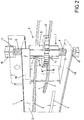
- Fig. 1 an angle piece 1 is shown through which a tensioning strap 2 designed as a wire rope is threaded. If more angle pieces 1 are threaded onto the tensioning strap 2, a ring can be created that is part of a substructure is used to attach a chimney cladding, the ring running around the chimney in an approximately horizontal orientation.
- the mentioned further angle pieces can be arranged freely movable on the tensioning band 2, while the angle piece 1 shown in the drawing has a clamping device 3 which is used to fix the tensioning band 2 and with which the tensioning band 2 can also be tensioned.
- FIG Fig. 1 only the angle piece 1 of the above-mentioned ring provided with the clamping device 3 is shown in FIG Fig. 1 shown.
- the angle piece 1 has several slots 4 so that the tensioning band 2 can run through some of these slots 4 and the angle piece 1 is thus retained on the tensioning band 2 in a captive manner. Except for the clamping device 3, the angle piece 1 consists of a single, multiple-edged stainless steel sheet metal blank. Where two legs 5 of the angle piece 1 running at right angles to one another meet along a contact line 6, the adjacent legs 5 can be connected to one another by welding points in order to increase the stability of the angle piece 1.
- the sheet metal of both legs 5 forms abutment surfaces which are beveled upwards and downwards, so that a large-area, gentle contact of the elbow 1 on a chimney is made possible.
- the outer sides of the legs 5 facing the viewer represent connection surfaces in which the slots 4 are used to attach other elements of the substructure of a chimney cladding, e.g. B. vertically extending strips. For example, mounting screws with a pointed end and a coarse thread can be screwed into the slots 4 in order to fasten these further elements to the angle piece 1.
- the clamping device 3 has a winding axis 7 which is formed by two screws 8 and a threaded sleeve 9.
- the two screws 8 extend from opposite sides into the threaded sleeve 9, and screw heads 10 of the screws 8 are located outside and at a distance from the relevant leg 5.
- the leg 5 has two aligned bores 11, so that the winding axis 7 in relation is mounted on the leg 5 so as to be axially movable.
- the threaded sleeve 9 has an outer circumference deviating from the circular shape, which is designed as a hexagon in the exemplary embodiment shown. With a matching, likewise hexagonal inner contour, a gear 12 is non-rotatably mounted on the threaded sleeve 9.
- a particularly inexpensive embodiment of the clamping device 3 is made possible by the fact that the gear wheel 12 is not fixed on the threaded sleeve 9, for example by gluing, welding or the like.
- the gear 12 has a fine toothing in that it has 25 teeth with a diameter of 3 cm.
- the gears extend asymmetrically radially outwards.
- the tensioning band 2 has a first end which protrudes only slightly beyond the threaded sleeve 9. In the vicinity of this first end and below the gear 12, the tensioning band 2 is fixed in the threaded sleeve 9. After the tightening strap 2 the Fig. 1 Describes the apparent loop, it is passed above the gear 12 for the second time through the threaded sleeve 9 and it extends further to a second end of the tensioning strap 2 in a direction leading to the viewer.
- tension band 2 runs through the threaded sleeve 9, it acts like a stop which limits the axial mobility of the gear 12 on the threaded sleeve 9, so that the gear 12 is fixed on the threaded sleeve 9 with a corresponding axial play.
- Fig. 2 shows the area of the winding axis 7 on a larger scale than Fig. 1 and from a different angle.
- Two transverse bores 14 can be seen in the threaded sleeve 9, above and below the gear 12, through which the tensioning band 2 runs.
- a lock 15 in the form of a sheet metal tab can be seen, which is formed by a correspondingly beveled section of the leg 5 and has a freewheel recess 16.
- Fig. 2 the clamping device 3 is in its release position in that the gear wheel 12 is aligned with the freewheel recess 16 and partially extends into it.
- the lock 15 is accordingly not effective and the winding axis 7 can be rotated about its longitudinal axis in any direction.
- the threaded sleeve 9 is just as spaced from the two side walls of the leg 5 as the two screw heads 10, so that the winding axis 7 is accordingly able to move axially in the axial direction.
- a lock nut 17 rests against the screw head 10 of the upper screw 8, so it is at the greatest possible distance from the leg 5, so that in this configuration the maximum mobility of the clamping device 3 is given both in the axial and in the direction of rotation.
- Fig. 3 shows that the lock nut 17 has been lowered on the upper screw until it rests against the leg 5.
- the entire winding axis 7 has been raised until the threaded sleeve 9 rests against the upper side wall of the leg 5 from the inside.
- the gear wheel 12 engages with the lock 15. Due to the asymmetrical design of the teeth, the gear wheel 12 enables a ratchet function in that it can still be rotated in one direction of rotation even in the locked position and in this way enables the tensioning strap 2 to be attached to the Wind up the winding shaft 7 and thus continue to tension it beyond the manually applied pretension.
- the length of the sheet metal tab which forms the lock 15 causes the lock 15 to be flexible in order to also enable the aforementioned ratchet function.
- the lock 15 prevents the gear wheel 12 from being reset Fig. 2 be brought so that the tensioning strap 2 can be relaxed in this configuration, for example to correct the position of the ring on the chimney or to dismantle the ring from the chimney.
- the transverse bores 14 are arranged in the threaded sleeve 9 according to the following boundary conditions:
- the transverse bore 14, which is closer to the lock nut 17, is the upper transverse bore 14, and the end of the threaded sleeve 9 which is closer to the lock nut 17 is also the upper end of the threaded sleeve 9.
- the upper transverse bore 14 is so far removed from the upper end of the threaded sleeve 9 that the threaded sleeve 9 can be moved up to the stop on the sheet metal of the leg 5 and held in this position by means of the lock nut 17 without the tension band 2 comes into collision with the upper edge web 18.
- the lower transverse bore 14 is so far removed from the lower end of the threaded sleeve 9 that in the Fig. 3 visible, raised or locked position of the winding axle 7 ensures that the gear 12 meshes with the lock 15 and is not positioned in front of the freewheel recess 16.
- a third boundary condition is that the two transverse bores 14 are spaced from one another so far that there is sufficient space between them for the arrangement of the gear wheel 12.
- the angle piece 1 can be used in the embodiment shown.
- manufacturing steps can be omitted in order to create a straight holder that the clamping device 3 carries: the angle piece 1 shown in the drawings consists, except for the clamping device 3, of a single, multiple-edged stainless steel sheet metal blank. Where two legs 5 of the angle piece 1 running at right angles to one another meet along a contact line 6, material has first been removed from this sheet metal blank, or the sheet metal blank has two notches far from the start, so that at least after the folding process, the two banks of the abut each notch on the contact line.
- no material is initially removed from the sheet metal blank or the sheet metal blank is initially produced without notches, and then the manufacturing step of edging is also omitted, so that the straight holder is particularly easy and inexpensive to manufacture.
Landscapes
- Engineering & Computer Science (AREA)
- Architecture (AREA)
- Civil Engineering (AREA)
- Structural Engineering (AREA)
- General Engineering & Computer Science (AREA)
- Mechanical Engineering (AREA)
- Clamps And Clips (AREA)
Applications Claiming Priority (1)
| Application Number | Priority Date | Filing Date | Title |
|---|---|---|---|
| DE202020103513.4U DE202020103513U1 (de) | 2020-06-18 | 2020-06-18 | Winkelstück, und Unterkonstruktion einer Schornsteinbekleidung |
Publications (2)
| Publication Number | Publication Date |
|---|---|
| EP3926122A1 true EP3926122A1 (fr) | 2021-12-22 |
| EP3926122B1 EP3926122B1 (fr) | 2023-09-06 |
Family
ID=72518652
Family Applications (1)
| Application Number | Title | Priority Date | Filing Date |
|---|---|---|---|
| EP21179624.8A Active EP3926122B1 (fr) | 2020-06-18 | 2021-06-15 | Pièce d'angle et sous-structure pour un revêtement de cheminée d'aération |
Country Status (2)
| Country | Link |
|---|---|
| EP (1) | EP3926122B1 (fr) |
| DE (1) | DE202020103513U1 (fr) |
Citations (3)
| Publication number | Priority date | Publication date | Assignee | Title |
|---|---|---|---|---|
| AT310915B (de) * | 1971-08-19 | 1973-10-25 | Ziegelwerk Rohr Obermair | Kamin aus Mantelsteinen und Innenrohren |
| DE3732152A1 (de) * | 1987-09-24 | 1989-04-06 | Thomas Koeglsperger | Verkleidung fuer rechteckige kamine |
| DE202015102792U1 (de) | 2015-05-29 | 2015-08-26 | Matthias Velken | Winkelstück |
-
2020
- 2020-06-18 DE DE202020103513.4U patent/DE202020103513U1/de not_active Expired - Lifetime
-
2021
- 2021-06-15 EP EP21179624.8A patent/EP3926122B1/fr active Active
Patent Citations (3)
| Publication number | Priority date | Publication date | Assignee | Title |
|---|---|---|---|---|
| AT310915B (de) * | 1971-08-19 | 1973-10-25 | Ziegelwerk Rohr Obermair | Kamin aus Mantelsteinen und Innenrohren |
| DE3732152A1 (de) * | 1987-09-24 | 1989-04-06 | Thomas Koeglsperger | Verkleidung fuer rechteckige kamine |
| DE202015102792U1 (de) | 2015-05-29 | 2015-08-26 | Matthias Velken | Winkelstück |
Also Published As
| Publication number | Publication date |
|---|---|
| EP3926122B1 (fr) | 2023-09-06 |
| DE202020103513U1 (de) | 2020-09-01 |
Similar Documents
| Publication | Publication Date | Title |
|---|---|---|
| EP3804121B1 (fr) | Installation solaire ayant un table de modules pivotantes et fixables | |
| DE3344185A1 (de) | Vorrichtung zum verhindern des ueberspannens der motorfeder in einem fensterrollo oder dergleichen | |
| EP3643847B1 (fr) | Système de fixation et rail pour un système de fixation | |
| EP3769018A1 (fr) | Unité de pivotement pour un dispositif de poursuite pour des modules solaires | |
| LU85715A1 (de) | Kraftschluessig-elastische schienenbefestigung fuer gleisanlagen | |
| EP3705676B1 (fr) | Procédé de montage d'un coffre de volet roulant et coffre de volet roulant posé sur une partie du cadre | |
| DE102008046166B4 (de) | Werkzeug für Zahnflankenspiel | |
| EP3926122B1 (fr) | Pièce d'angle et sous-structure pour un revêtement de cheminée d'aération | |
| EP0011239B2 (fr) | Mur de protection acoustique | |
| DE9403006U1 (de) | Sonnenschutzvorrichtung | |
| EP1092881A2 (fr) | Dispositif de fixation ou d'assemblage d'éléments de construction | |
| DE3131537A1 (de) | "eckverbindung" | |
| CH693161A5 (de) | Ausziehvorrichtung eines Hochschrankes. | |
| DE102014004160B3 (de) | Einrichtung zum Spannen von Strangelementen | |
| DE2645952A1 (de) | Leiter mit rueckenschutz | |
| EP0704011B1 (fr) | Systeme et element de liaison de pieces en bois | |
| EP3983625A1 (fr) | Noeud d'échafaudage, rosette d'échafaudage, tige d'échafaudage et montant d'échafaudage, et procédé de fabrication pour une rosette d'échafaudage | |
| DE102023119208B3 (de) | Hebe- und Transportvorrichtung | |
| EP0422254B1 (fr) | Plafond filtrant spécialement pour chambres de pulvérisation | |
| EP2090736B1 (fr) | Store | |
| EP1471190B1 (fr) | Mécanisme de serrage | |
| AT408784B (de) | Anordnung zum befestigen von im wesentlichen u-förmigen führungsschienen für rolladen sowie baugruppe aus führungsschiene und halteteilen für eine solche anordnung | |
| DE2404812A1 (de) | Schieberlueftung, insbesondere fuer tueren, fenster und dgl. | |
| EP0317695A1 (fr) | Echafaudage métallique pour le bâtiment | |
| DE102017129293A1 (de) | Transportvorrichtung |
Legal Events
| Date | Code | Title | Description |
|---|---|---|---|
| PUAI | Public reference made under article 153(3) epc to a published international application that has entered the european phase |
Free format text: ORIGINAL CODE: 0009012 |
|
| STAA | Information on the status of an ep patent application or granted ep patent |
Free format text: STATUS: THE APPLICATION HAS BEEN PUBLISHED |
|
| AK | Designated contracting states |
Kind code of ref document: A1 Designated state(s): AL AT BE BG CH CY CZ DE DK EE ES FI FR GB GR HR HU IE IS IT LI LT LU LV MC MK MT NL NO PL PT RO RS SE SI SK SM TR |
|
| B565 | Issuance of search results under rule 164(2) epc |
Effective date: 20211118 |
|
| STAA | Information on the status of an ep patent application or granted ep patent |
Free format text: STATUS: REQUEST FOR EXAMINATION WAS MADE |
|
| 17P | Request for examination filed |
Effective date: 20220610 |
|
| RBV | Designated contracting states (corrected) |
Designated state(s): AL AT BE BG CH CY CZ DE DK EE ES FI FR GB GR HR HU IE IS IT LI LT LU LV MC MK MT NL NO PL PT RO RS SE SI SK SM TR |
|
| GRAP | Despatch of communication of intention to grant a patent |
Free format text: ORIGINAL CODE: EPIDOSNIGR1 |
|
| STAA | Information on the status of an ep patent application or granted ep patent |
Free format text: STATUS: GRANT OF PATENT IS INTENDED |
|
| INTG | Intention to grant announced |
Effective date: 20221028 |
|
| GRAJ | Information related to disapproval of communication of intention to grant by the applicant or resumption of examination proceedings by the epo deleted |
Free format text: ORIGINAL CODE: EPIDOSDIGR1 |
|
| STAA | Information on the status of an ep patent application or granted ep patent |
Free format text: STATUS: REQUEST FOR EXAMINATION WAS MADE |
|
| INTC | Intention to grant announced (deleted) | ||
| GRAP | Despatch of communication of intention to grant a patent |
Free format text: ORIGINAL CODE: EPIDOSNIGR1 |
|
| STAA | Information on the status of an ep patent application or granted ep patent |
Free format text: STATUS: GRANT OF PATENT IS INTENDED |
|
| INTG | Intention to grant announced |
Effective date: 20230510 |
|
| GRAS | Grant fee paid |
Free format text: ORIGINAL CODE: EPIDOSNIGR3 |
|
| GRAA | (expected) grant |
Free format text: ORIGINAL CODE: 0009210 |
|
| STAA | Information on the status of an ep patent application or granted ep patent |
Free format text: STATUS: THE PATENT HAS BEEN GRANTED |
|
| AK | Designated contracting states |
Kind code of ref document: B1 Designated state(s): AL AT BE BG CH CY CZ DE DK EE ES FI FR GB GR HR HU IE IS IT LI LT LU LV MC MK MT NL NO PL PT RO RS SE SI SK SM TR |
|
| REG | Reference to a national code |
Ref country code: GB Ref legal event code: FG4D Free format text: NOT ENGLISH |
|
| REG | Reference to a national code |
Ref country code: CH Ref legal event code: EP |
|
| REG | Reference to a national code |
Ref country code: IE Ref legal event code: FG4D Free format text: LANGUAGE OF EP DOCUMENT: GERMAN |
|
| REG | Reference to a national code |
Ref country code: DE Ref legal event code: R096 Ref document number: 502021001420 Country of ref document: DE |
|
| REG | Reference to a national code |
Ref country code: LT Ref legal event code: MG9D |
|
| REG | Reference to a national code |
Ref country code: NL Ref legal event code: MP Effective date: 20230906 |
|
| P01 | Opt-out of the competence of the unified patent court (upc) registered |
Effective date: 20231208 |
|
| PG25 | Lapsed in a contracting state [announced via postgrant information from national office to epo] |
Ref country code: GR Free format text: LAPSE BECAUSE OF FAILURE TO SUBMIT A TRANSLATION OF THE DESCRIPTION OR TO PAY THE FEE WITHIN THE PRESCRIBED TIME-LIMIT Effective date: 20231207 |
|
| PG25 | Lapsed in a contracting state [announced via postgrant information from national office to epo] |
Ref country code: SE Free format text: LAPSE BECAUSE OF FAILURE TO SUBMIT A TRANSLATION OF THE DESCRIPTION OR TO PAY THE FEE WITHIN THE PRESCRIBED TIME-LIMIT Effective date: 20230906 Ref country code: RS Free format text: LAPSE BECAUSE OF FAILURE TO SUBMIT A TRANSLATION OF THE DESCRIPTION OR TO PAY THE FEE WITHIN THE PRESCRIBED TIME-LIMIT Effective date: 20230906 Ref country code: NO Free format text: LAPSE BECAUSE OF FAILURE TO SUBMIT A TRANSLATION OF THE DESCRIPTION OR TO PAY THE FEE WITHIN THE PRESCRIBED TIME-LIMIT Effective date: 20231206 Ref country code: LV Free format text: LAPSE BECAUSE OF FAILURE TO SUBMIT A TRANSLATION OF THE DESCRIPTION OR TO PAY THE FEE WITHIN THE PRESCRIBED TIME-LIMIT Effective date: 20230906 Ref country code: LT Free format text: LAPSE BECAUSE OF FAILURE TO SUBMIT A TRANSLATION OF THE DESCRIPTION OR TO PAY THE FEE WITHIN THE PRESCRIBED TIME-LIMIT Effective date: 20230906 Ref country code: HR Free format text: LAPSE BECAUSE OF FAILURE TO SUBMIT A TRANSLATION OF THE DESCRIPTION OR TO PAY THE FEE WITHIN THE PRESCRIBED TIME-LIMIT Effective date: 20230906 Ref country code: GR Free format text: LAPSE BECAUSE OF FAILURE TO SUBMIT A TRANSLATION OF THE DESCRIPTION OR TO PAY THE FEE WITHIN THE PRESCRIBED TIME-LIMIT Effective date: 20231207 Ref country code: FI Free format text: LAPSE BECAUSE OF FAILURE TO SUBMIT A TRANSLATION OF THE DESCRIPTION OR TO PAY THE FEE WITHIN THE PRESCRIBED TIME-LIMIT Effective date: 20230906 |
|
| PG25 | Lapsed in a contracting state [announced via postgrant information from national office to epo] |
Ref country code: NL Free format text: LAPSE BECAUSE OF FAILURE TO SUBMIT A TRANSLATION OF THE DESCRIPTION OR TO PAY THE FEE WITHIN THE PRESCRIBED TIME-LIMIT Effective date: 20230906 |
|
| PG25 | Lapsed in a contracting state [announced via postgrant information from national office to epo] |
Ref country code: IS Free format text: LAPSE BECAUSE OF FAILURE TO SUBMIT A TRANSLATION OF THE DESCRIPTION OR TO PAY THE FEE WITHIN THE PRESCRIBED TIME-LIMIT Effective date: 20240106 |
|
| PG25 | Lapsed in a contracting state [announced via postgrant information from national office to epo] |
Ref country code: ES Free format text: LAPSE BECAUSE OF FAILURE TO SUBMIT A TRANSLATION OF THE DESCRIPTION OR TO PAY THE FEE WITHIN THE PRESCRIBED TIME-LIMIT Effective date: 20230906 |
|
| PG25 | Lapsed in a contracting state [announced via postgrant information from national office to epo] |
Ref country code: SM Free format text: LAPSE BECAUSE OF FAILURE TO SUBMIT A TRANSLATION OF THE DESCRIPTION OR TO PAY THE FEE WITHIN THE PRESCRIBED TIME-LIMIT Effective date: 20230906 Ref country code: RO Free format text: LAPSE BECAUSE OF FAILURE TO SUBMIT A TRANSLATION OF THE DESCRIPTION OR TO PAY THE FEE WITHIN THE PRESCRIBED TIME-LIMIT Effective date: 20230906 Ref country code: IS Free format text: LAPSE BECAUSE OF FAILURE TO SUBMIT A TRANSLATION OF THE DESCRIPTION OR TO PAY THE FEE WITHIN THE PRESCRIBED TIME-LIMIT Effective date: 20240106 Ref country code: ES Free format text: LAPSE BECAUSE OF FAILURE TO SUBMIT A TRANSLATION OF THE DESCRIPTION OR TO PAY THE FEE WITHIN THE PRESCRIBED TIME-LIMIT Effective date: 20230906 Ref country code: EE Free format text: LAPSE BECAUSE OF FAILURE TO SUBMIT A TRANSLATION OF THE DESCRIPTION OR TO PAY THE FEE WITHIN THE PRESCRIBED TIME-LIMIT Effective date: 20230906 Ref country code: CZ Free format text: LAPSE BECAUSE OF FAILURE TO SUBMIT A TRANSLATION OF THE DESCRIPTION OR TO PAY THE FEE WITHIN THE PRESCRIBED TIME-LIMIT Effective date: 20230906 Ref country code: PT Free format text: LAPSE BECAUSE OF FAILURE TO SUBMIT A TRANSLATION OF THE DESCRIPTION OR TO PAY THE FEE WITHIN THE PRESCRIBED TIME-LIMIT Effective date: 20240108 Ref country code: SK Free format text: LAPSE BECAUSE OF FAILURE TO SUBMIT A TRANSLATION OF THE DESCRIPTION OR TO PAY THE FEE WITHIN THE PRESCRIBED TIME-LIMIT Effective date: 20230906 |
|
| PG25 | Lapsed in a contracting state [announced via postgrant information from national office to epo] |
Ref country code: PL Free format text: LAPSE BECAUSE OF FAILURE TO SUBMIT A TRANSLATION OF THE DESCRIPTION OR TO PAY THE FEE WITHIN THE PRESCRIBED TIME-LIMIT Effective date: 20230906 Ref country code: IT Free format text: LAPSE BECAUSE OF FAILURE TO SUBMIT A TRANSLATION OF THE DESCRIPTION OR TO PAY THE FEE WITHIN THE PRESCRIBED TIME-LIMIT Effective date: 20230906 |
|
| REG | Reference to a national code |
Ref country code: DE Ref legal event code: R097 Ref document number: 502021001420 Country of ref document: DE |
|
| PG25 | Lapsed in a contracting state [announced via postgrant information from national office to epo] |
Ref country code: DK Free format text: LAPSE BECAUSE OF FAILURE TO SUBMIT A TRANSLATION OF THE DESCRIPTION OR TO PAY THE FEE WITHIN THE PRESCRIBED TIME-LIMIT Effective date: 20230906 |
|
| PLBE | No opposition filed within time limit |
Free format text: ORIGINAL CODE: 0009261 |
|
| STAA | Information on the status of an ep patent application or granted ep patent |
Free format text: STATUS: NO OPPOSITION FILED WITHIN TIME LIMIT |
|
| PG25 | Lapsed in a contracting state [announced via postgrant information from national office to epo] |
Ref country code: DK Free format text: LAPSE BECAUSE OF FAILURE TO SUBMIT A TRANSLATION OF THE DESCRIPTION OR TO PAY THE FEE WITHIN THE PRESCRIBED TIME-LIMIT Effective date: 20230906 Ref country code: SI Free format text: LAPSE BECAUSE OF FAILURE TO SUBMIT A TRANSLATION OF THE DESCRIPTION OR TO PAY THE FEE WITHIN THE PRESCRIBED TIME-LIMIT Effective date: 20230906 |
|
| 26N | No opposition filed |
Effective date: 20240607 |
|
| PG25 | Lapsed in a contracting state [announced via postgrant information from national office to epo] |
Ref country code: BG Free format text: LAPSE BECAUSE OF FAILURE TO SUBMIT A TRANSLATION OF THE DESCRIPTION OR TO PAY THE FEE WITHIN THE PRESCRIBED TIME-LIMIT Effective date: 20230906 |
|
| PG25 | Lapsed in a contracting state [announced via postgrant information from national office to epo] |
Ref country code: BG Free format text: LAPSE BECAUSE OF FAILURE TO SUBMIT A TRANSLATION OF THE DESCRIPTION OR TO PAY THE FEE WITHIN THE PRESCRIBED TIME-LIMIT Effective date: 20230906 |
|
| PG25 | Lapsed in a contracting state [announced via postgrant information from national office to epo] |
Ref country code: MC Free format text: LAPSE BECAUSE OF FAILURE TO SUBMIT A TRANSLATION OF THE DESCRIPTION OR TO PAY THE FEE WITHIN THE PRESCRIBED TIME-LIMIT Effective date: 20230906 |
|
| PG25 | Lapsed in a contracting state [announced via postgrant information from national office to epo] |
Ref country code: LU Free format text: LAPSE BECAUSE OF NON-PAYMENT OF DUE FEES Effective date: 20240615 |
|
| PG25 | Lapsed in a contracting state [announced via postgrant information from national office to epo] |
Ref country code: IE Free format text: LAPSE BECAUSE OF NON-PAYMENT OF DUE FEES Effective date: 20240615 |
|
| PG25 | Lapsed in a contracting state [announced via postgrant information from national office to epo] |
Ref country code: BE Free format text: LAPSE BECAUSE OF NON-PAYMENT OF DUE FEES Effective date: 20240630 |
|
| REG | Reference to a national code |
Ref country code: BE Ref legal event code: MM Effective date: 20240630 |
|
| PGFP | Annual fee paid to national office [announced via postgrant information from national office to epo] |
Ref country code: DE Payment date: 20250630 Year of fee payment: 5 |
|
| PGFP | Annual fee paid to national office [announced via postgrant information from national office to epo] |
Ref country code: GB Payment date: 20250618 Year of fee payment: 5 |
|
| PGFP | Annual fee paid to national office [announced via postgrant information from national office to epo] |
Ref country code: FR Payment date: 20250627 Year of fee payment: 5 |
|
| PGFP | Annual fee paid to national office [announced via postgrant information from national office to epo] |
Ref country code: AT Payment date: 20250721 Year of fee payment: 5 |
|
| PGFP | Annual fee paid to national office [announced via postgrant information from national office to epo] |
Ref country code: CH Payment date: 20250701 Year of fee payment: 5 |
|
| PG25 | Lapsed in a contracting state [announced via postgrant information from national office to epo] |
Ref country code: CY Free format text: LAPSE BECAUSE OF FAILURE TO SUBMIT A TRANSLATION OF THE DESCRIPTION OR TO PAY THE FEE WITHIN THE PRESCRIBED TIME-LIMIT; INVALID AB INITIO Effective date: 20210615 |
|
| PG25 | Lapsed in a contracting state [announced via postgrant information from national office to epo] |
Ref country code: HU Free format text: LAPSE BECAUSE OF FAILURE TO SUBMIT A TRANSLATION OF THE DESCRIPTION OR TO PAY THE FEE WITHIN THE PRESCRIBED TIME-LIMIT; INVALID AB INITIO Effective date: 20210615 |