EP3926347B1 - Optical fiber winding for measuring the current circulating through a conductor and optical fiber-based current measuring equipment - Google Patents
Optical fiber winding for measuring the current circulating through a conductor and optical fiber-based current measuring equipment Download PDFInfo
- Publication number
- EP3926347B1 EP3926347B1 EP20382515.3A EP20382515A EP3926347B1 EP 3926347 B1 EP3926347 B1 EP 3926347B1 EP 20382515 A EP20382515 A EP 20382515A EP 3926347 B1 EP3926347 B1 EP 3926347B1
- Authority
- EP
- European Patent Office
- Prior art keywords
- optical fiber
- cable
- rotation direction
- central support
- support core
- Prior art date
- Legal status (The legal status is an assumption and is not a legal conclusion. Google has not performed a legal analysis and makes no representation as to the accuracy of the status listed.)
- Active
Links
Images


Classifications
-
- G—PHYSICS
- G01—MEASURING; TESTING
- G01R—MEASURING ELECTRIC VARIABLES; MEASURING MAGNETIC VARIABLES
- G01R15/00—Details of measuring arrangements of the types provided for in groups G01R17/00 - G01R29/00, G01R33/00 - G01R33/26 or G01R35/00
- G01R15/14—Adaptations providing voltage or current isolation, e.g. for high-voltage or high-current networks
- G01R15/24—Adaptations providing voltage or current isolation, e.g. for high-voltage or high-current networks using light-modulating devices
- G01R15/245—Adaptations providing voltage or current isolation, e.g. for high-voltage or high-current networks using light-modulating devices using magneto-optical modulators, e.g. based on the Faraday or Cotton-Mouton effect
- G01R15/246—Adaptations providing voltage or current isolation, e.g. for high-voltage or high-current networks using light-modulating devices using magneto-optical modulators, e.g. based on the Faraday or Cotton-Mouton effect based on the Faraday, i.e. linear magneto-optic, effect
-
- G—PHYSICS
- G01—MEASURING; TESTING
- G01R—MEASURING ELECTRIC VARIABLES; MEASURING MAGNETIC VARIABLES
- G01R15/00—Details of measuring arrangements of the types provided for in groups G01R17/00 - G01R29/00, G01R33/00 - G01R33/26 or G01R35/00
- G01R15/14—Adaptations providing voltage or current isolation, e.g. for high-voltage or high-current networks
- G01R15/24—Adaptations providing voltage or current isolation, e.g. for high-voltage or high-current networks using light-modulating devices
- G01R15/247—Details of the circuitry or construction of devices covered by G01R15/241 - G01R15/246
-
- G—PHYSICS
- G01—MEASURING; TESTING
- G01R—MEASURING ELECTRIC VARIABLES; MEASURING MAGNETIC VARIABLES
- G01R33/00—Arrangements or instruments for measuring magnetic variables
- G01R33/02—Measuring direction or magnitude of magnetic fields or magnetic flux
- G01R33/032—Measuring direction or magnitude of magnetic fields or magnetic flux using magneto-optic devices, e.g. Faraday or Cotton-Mouton effect
- G01R33/0322—Measuring direction or magnitude of magnetic fields or magnetic flux using magneto-optic devices, e.g. Faraday or Cotton-Mouton effect using the Faraday or Voigt effect
Definitions
- the present invention relates to an optical fiber winding and optical fiber-based current measuring equipment for measuring the current circulating through a conductor.
- Measuring equipment based on optical fiber for measuring the current circulating through a conductor operates according to the Faraday effect, i.e., the magnetic field generated by the current circulating through the conductor causes a rotation in the polarization of the light circulating through the optical fiber winding arranged around the conductor.
- the operation of said measuring equipment consists of emitting light through optical fiber to the optical fiber winding in which the characteristics of the light are modified depending on the current circulating through the conductor, and analyzing the rotation caused in the polarization of light so as to determine the magnitude of the current circulating through the conductor.
- the polarization of light of a perfectly circular single-mode optical fiber in which said light is propagated in a longitudinal propagation direction remains unchanged if it receives no external actions of any type. That is, theoretically speaking, the polarization of light at the inlet of the optical fiber would be identical to the polarization of light at the outlet of the optical fiber. Therefore, in the event of the action of a magnetic field generated by the current circulating through a conductor, the rotation in the polarization of light would only be due to the current circulating through the conductor.
- the polarization of light within an optical fiber presents a fairly random behavior which hinders measuring current.
- the core of the optical fiber is not perfectly circular; when the optical fiber is arranged around the conductor mechanical stresses which are not homogeneous along its longitudinal extension are created; optical fiber is an element with an elastic behavior which can be twisted and bent. All of this causes changes in the polarization of light.
- GB2190744A shows an apparatus for sensing magnetics fields by means of the Faraday effect which comprises two spun highly birefringent fibers which have a diminished birefringence produced by spinning during the drawing process.
- the two spun highly birefringent fibers are arranged in a helical manner around a central support core.
- EP0108012A1 shows an apparatus for measuring electric intensity using the Faraday effect.
- DE3115433A1 shows a measuring device for magneto-optical current measurement.
- JP2010266262A shows an optical fiber structure that reduces complexity in the work for winding an optical fiber, and also shows a method of mounting the same.
- EP3104183A1 or EP3598149A1 both belonging to the same applicant as the present invention, disclose optical fiber-based current measuring equipment for measuring the current circulating through a conductor, comprising an interrogator with light-emitting means and light-receiving means, a sensing portion close to the conductor, and an optical fiber transmission means arranged between the interrogator and the sensing portion.
- the object of the invention is to provide an optical fiber winding and optical fiber-based current measuring equipment for measuring the current circulating through a conductor, as defined in the claims.
- a first aspect of the invention relates to an optical fiber winding for measuring the current circulating through a conductor, comprising:
- the optical fiber cables extend in a helical manner around the central support core.
- the optical fiber cables are standard single-mode optical fiber cables.
- the first optical fiber cable is twisted about its longitudinal axis in a first twist direction
- the second optical fiber cable is twisted about its longitudinal axis in a second twist direction, the first twist direction being opposite the second twist direction, so that, since the optical fiber cables are twisted in opposite directions, the efforts that said optical fiber cables make to recover their shape are counteracted.
- a second aspect of the invention relates to optical fiber-based current measuring equipment for measuring the current circulating through a conductor, comprising:
- the twisting of the optical fiber allows single-mode optical fiber cables to be used for measuring the current circulating through the conductor.
- the twisting of the optical fiber is one of the factors changing the polarity of the light circulating through the optical fiber, such that by applying twisting on the longitudinal axis of the fiber, the remaining factors changing the polarity of light can be considered negligible with respect to the twisting factor. Therefore, by introducing controlled twisting in the optical fiber allows for the changes in the polarization of light basically being due to the magnetic field caused by the current circulating through the conductor, where the other factors can be considered irrelevant for the measurement of the current.
- optical fiber is an elastic element which tends to recover its original shape when twisting is no longer applied.
- the two optical fiber cables twisted in opposite directions and arranged around the central support core allow obtaining a stable mechanical assembly which can be readily wound around the conductor the current of which is to be measured.
- the natural tendency of optical fiber cables is to return to their natural position, but since the cables are twisted in opposite directions, they will make efforts to recover their shape which will be counteracted.
- a winding which is free of mechanical stresses and can be used as an optical fiber assembly for measuring the current of a conductor is thereby obtained.
- the optical fiber winding can be arranged around the conductor, with the optical fibers of the winding remaining twisted around the central support core, without loops or bends arising which hinder the placement of the winding on the conductor.
- the invention relates to an optical fiber winding 100 arranged around a conductor 5 for measuring the current I circulating through the conductor 5.
- the optical fiber winding 100 operates according to the Faraday effect.
- the magnetic field generated by the current I circulating through the conductor 5 causes a rotation in the polarization of the light circulating through the optical fiber winding 100 arranged around the conductor 5.
- the optical fiber winding 100 comprises a central support core 110 extending in a longitudinal direction Z, a first optical fiber cable 120 arranged around the central support core 110, and a second optical fiber cable 130 arranged around the central support core 110.
- the optical fiber cables 120 and 130 extend in a helical manner around the central support core 110 in the longitudinal direction Z.
- the first optical fiber cable 120 is twisted about its longitudinal axis Z1 in a first twist direction T1
- the second optical fiber cable 130 is twisted about its longitudinal axis Z2 in a second twist direction T2, the first twist direction T1 being opposite the second twist direction T2.
- Twisting is understood as the optical fiber cables 120 and 130 being rotated about their longitudinal axes a certain number of turns.
- the material with which the optical fiber cables are made has an elastic behavior, such that when a force is applied on the cable, the shape of the cable is modified, but when is removed said force, the elastic behavior of the cable tends to return it to its natural position.
- the configuration of the optical fiber winding 100 of the invention solves that problem.
- the central support core 110 keeps the optical fiber cables 120 and 130 extended in the longitudinal direction Z, impeding the natural tendency of the fiber to go back to its natural position. Furthermore, since the cables 120 and 130 are twisted in opposite directions, they make efforts to recover their shape that are counteracted. All this allows a mechanical stability of the optical fiber winding 100 without the need to apply external forces to maintain said stability.
- a force can be applied at each end of the cable and in the opposite direction, i.e., the optical fiber cables 120 and 130 can be longitudinally stressed from their ends to keep them twisted.
- longitudinal tension causes the optical fiber cable to acquire an elliptical instead of circular shape, i.e., linear birefringence increases, which causes the measurement capacity to be reduced.
- the previously described arrangement of the winding 100 allows maintaining the twisting of the cables 120 and 130 without having to apply longitudinal tension in the cables.
- Figure 5 shows an example of optical fiber-based current measuring equipment for measuring the current circulating through a conductor 5.
- the equipment comprises an interrogator 1 with light-emitting means 2 and light-receiving means 3, a sensing portion 4 close to the conductor 5, and optical fiber transmission means 6 arranged between the interrogator 1 and the sensing portion 4.
- the sensing portion 4 comprises an optical fiber winding 100 such as the one previously described, which is arranged around the conductor 5 for measuring the current I circulating through the conductor 5.
- the operation of the measuring equipment consists of emitting light through the optical fiber transmission means 6 to the optical fiber winding 100 in which the features of the light are modified depending on the current I circulating through the conductor 5, and analyzing the rotation caused in the polarization of the light so as to determine the magnitude of the current I circulating through the conductor 5.
- Pulses of light are sent from the light-emitting means 2 of the interrogator 1 to the optical fiber winding 100 of the sensing portion 4 through the optical fiber transmission means 6.
- the pulses are reflected in reflection means 7, such as a Faraday mirror, or a normal mirror, and return through the optical fiber winding 100, being directed towards the light-receiving means 3 of the interrogator 1 through the optical fiber transmission means 6.
- the interrogator 1 is located away from the sensing portion 4 for measuring the current I remotely, and the optical fiber transmission means 6 allow connecting the interrogator 1 with the sensing portion 4 at large distances.
- Figure 5 illustrates the optical fiber winding 100 arranged in a helical manner around the conductor 5.
- the optical fiber winding 100 can be arranged on an optical fiber reel.
- the winding 100 is therefore not arranged in a helical manner on the conductor 5, but rather the winding 100 is wound up a certain number of turns forming a loop inside the reel, and the conductor 5 is passed through the center of said reel.
- the reel is arranged transversely with respect to the longitudinal direction in which the conductor extends.
- Figures 1 and 2 show first and second embodiments of the optical fiber winding 100.
- the first optical fiber cable 120 extends in a helical manner around the central support core 110 according to a first rotation direction R1
- the second optical fiber cable 130 extends in a helical manner around the central support core 110 according to a second rotation direction R2, the first rotation direction R1 being opposite the second rotation direction R2, such that the optical fiber cables 120,130 are interlaced with one another around the central support core 110. Therefore, every time the cables 120 and 130 are interlaced, a contact area is created between both which favors the cables maintaining the twisting and their stability on the core central 110.
- the first twist direction T1 of the first cable 120 is counterclockwise
- the first rotation direction R1 of the first cable 120 is counterclockwise
- the second twist direction T2 of the second cable 130 is clockwise
- the second rotation direction R2 of the second cable 130 is clockwise.
- first twist direction T1 of the first cable 120 is clockwise
- first rotation direction R1 of the first cable 120 is counterclockwise
- second twist direction T2 of the second cable 130 is counterclockwise
- the second rotation direction R2 of the second cable 130 is clockwise.
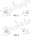
- Figures 3 and 4 show third and fourth embodiments of the optical fiber winding 100.
- the first optical fiber cable 120 extends in a helical manner around the central support core 110 according to a first rotation direction R1
- the second optical fiber cable 130 extends in a helical manner around the central support core 110 according to a second rotation direction R2, the first rotation direction R1 being the same as the second rotation direction R2, and the optical fiber cables 120 and 130 being in contact with one another along their entire longitudinal extension around the central support core 110.
- the cables 120 and 130 are not interlaced with one another, such that retaining points between them are not created; however, the cables 120 and 130 are at all times in contact with the central support core 110 and with one another.
- first twist direction T1 of the first cable 120 is counterclockwise
- second twist direction T2 of the second cable 130 is clockwise
- first rotation direction R1 of the first cable 120 and the second rotation direction R2 of the second cable 130 are counterclockwise.
- first twist direction T1 of the first cable 120 is clockwise
- second twist direction T2 of the second cable 130 is counterclockwise
- first rotation direction R1 of the first cable 120 and the second rotation direction R2 of the second cable 130 are clockwise.
- the first optical fiber cable 120 is twisted about its longitudinal axis Z1 a first number of turns
- the second optical fiber cable 130 is twisted about its longitudinal axis Z2 a second number of turns, the first and the second number of turns being the same.
- the twisting of both cables is therefore the same, and the behavior of the polarization of light in both cables is therefore similar. This feature allows applying methods for measuring current in which it is necessary for both cables to emit optical signals in order to carry out the measurement.
- the optical fiber cables 120 and 130 are twisted 12 ⁇ 2 ⁇ rad m , i.e., the cables are twisted 12 certain turns for each meter of cable.
- the central support core 110 can be a mechanical element, such as a metal or plastic cable.
- the central support core 110 is made up of one or more optical fiber cables. This arrangement allows emitting an additional number of optical signals which can be used for applying different methods for measuring the current I circulating through the conductor 5.
- the optical fiber cables 120 and 130 are standard single-mode optical fiber cables of the type normally used in the telecommunication sector.
- the twisting of the optical fiber cables 120 and 130 allows being able to use single-mode optical fiber cables to perform the measurement of the current of the conductor 5. Therefore, by using standard optical fiber cables a low-cost optical fiber winding 100 is obtained to perform current measurements, which is particularly relevant when the current in long cables for carrying electrical energy is to be measured.
- the optical fiber winding 100 may be 100 meters long.
- a single-mode optical fiber cable generally comprises a core, a cladding surrounding the core, a buffer surrounding the cladding, and a jacket surrounding the buffer.
- the core is the physical component that carries light and is generally made of glass fiber
- the cladding protects the core and allows the propagation of the light.
- the buffer and the jacket are elements generally made of rigid plastic which provide protection and stiffness to the optical fiber cable.
- E xo E yo cos ⁇ l + j ⁇ l 2 ⁇ sin ⁇ l ⁇ + ⁇ c 2 ⁇ sin ⁇ l ⁇ ⁇ + ⁇ c 2 ⁇ sin ⁇ l cos ⁇ l ⁇ j ⁇ l 2 ⁇ sin ⁇ l E xi E yi
- the twisting may be unstable once certain levels of magnitude are reached, the light is required to pass through the turns of the winding 100, to be reflected in the mirror 7 and to go back through said turns of the winding 100, such that the effect of mechanical twisting is cancelled out, and given that the effect of the magnetic field is not symmetrical, the magnetic field measurement is doubled.
- the invention proposes twisting the optical fiber cables 120 and 130 to preferably be able to use standard single-mode optical fiber cables for measuring current.
- the manner in which the optical fiber winding 100 is performed allows maintaining the twisting of the optical fiber cables 120 and 130 without the need to use external forces or elements.
Landscapes
- Engineering & Computer Science (AREA)
- Power Engineering (AREA)
- Physics & Mathematics (AREA)
- General Physics & Mathematics (AREA)
- Condensed Matter Physics & Semiconductors (AREA)
- Measuring Instrument Details And Bridges, And Automatic Balancing Devices (AREA)
Priority Applications (5)
| Application Number | Priority Date | Filing Date | Title |
|---|---|---|---|
| DK20382515.3T DK3926347T3 (da) | 2020-06-15 | 2020-06-15 | Optisk fibervikling til måling af strømmen, der cirkulerer gennem en leder og strømmåleudstyr baseret på optisk fiber |
| ES20382515T ES2995076T3 (en) | 2020-06-15 | 2020-06-15 | Optical fiber winding for measuring the current circulating through a conductor and optical fiber-based current measuring equipment |
| EP20382515.3A EP3926347B1 (en) | 2020-06-15 | 2020-06-15 | Optical fiber winding for measuring the current circulating through a conductor and optical fiber-based current measuring equipment |
| US17/340,462 US11519942B2 (en) | 2020-06-15 | 2021-06-07 | Optical fiber winding for measuring the current circulating through a conductor, and optical fiber-based current measuring equipment |
| US17/868,102 US11693034B2 (en) | 2020-06-15 | 2022-07-19 | Optical fiber winding for measuring the current circulating through a conductor, and optical fiber-based current measuring equipment |
Applications Claiming Priority (1)
| Application Number | Priority Date | Filing Date | Title |
|---|---|---|---|
| EP20382515.3A EP3926347B1 (en) | 2020-06-15 | 2020-06-15 | Optical fiber winding for measuring the current circulating through a conductor and optical fiber-based current measuring equipment |
Publications (2)
| Publication Number | Publication Date |
|---|---|
| EP3926347A1 EP3926347A1 (en) | 2021-12-22 |
| EP3926347B1 true EP3926347B1 (en) | 2024-08-21 |
Family
ID=71409352
Family Applications (1)
| Application Number | Title | Priority Date | Filing Date |
|---|---|---|---|
| EP20382515.3A Active EP3926347B1 (en) | 2020-06-15 | 2020-06-15 | Optical fiber winding for measuring the current circulating through a conductor and optical fiber-based current measuring equipment |
Country Status (4)
| Country | Link |
|---|---|
| US (2) | US11519942B2 (da) |
| EP (1) | EP3926347B1 (da) |
| DK (1) | DK3926347T3 (da) |
| ES (1) | ES2995076T3 (da) |
Family Cites Families (6)
| Publication number | Priority date | Publication date | Assignee | Title |
|---|---|---|---|---|
| DE3115433A1 (de) * | 1981-04-16 | 1982-11-11 | Philips Kommunikations Industrie AG, 8500 Nürnberg | "messvorrichtung zur magneto-optischen strommessung" |
| EP0108012A1 (fr) * | 1982-10-28 | 1984-05-09 | Commissariat à l'Energie Atomique | Dispositif de mesure d'intensité électrique à effet Faraday |
| GB8612190D0 (en) * | 1986-05-20 | 1986-07-16 | Qian J R | Optical fibre apparatus |
| JP2010266262A (ja) * | 2009-05-13 | 2010-11-25 | Yazaki Corp | 光ファイバ構造体及びその取付方法 |
| EP3104183A1 (en) * | 2015-06-10 | 2016-12-14 | Lumiker Aplicaciones Tecnologicas S.L. | Current measuring equipment based on optical fiber for measuring the current circulating through a conductor and the associated method |
| EP3598149A1 (en) | 2018-07-19 | 2020-01-22 | Lumiker Aplicaciones Tecnologicas S.L. | Method for measuring the current circulating through at least one conductor with optical fiber-based measuring equipment, and measuring equipment |
-
2020
- 2020-06-15 DK DK20382515.3T patent/DK3926347T3/da active
- 2020-06-15 ES ES20382515T patent/ES2995076T3/es active Active
- 2020-06-15 EP EP20382515.3A patent/EP3926347B1/en active Active
-
2021
- 2021-06-07 US US17/340,462 patent/US11519942B2/en active Active
-
2022
- 2022-07-19 US US17/868,102 patent/US11693034B2/en active Active
Also Published As
| Publication number | Publication date |
|---|---|
| US11519942B2 (en) | 2022-12-06 |
| US11693034B2 (en) | 2023-07-04 |
| US20210389350A1 (en) | 2021-12-16 |
| DK3926347T3 (da) | 2024-11-11 |
| EP3926347A1 (en) | 2021-12-22 |
| US20220365113A1 (en) | 2022-11-17 |
| ES2995076T3 (en) | 2025-02-06 |
Similar Documents
| Publication | Publication Date | Title |
|---|---|---|
| US4255018A (en) | Fibre optical arrangement for measuring the intensity of an electric current | |
| Bertholds et al. | Determination of the individual strain-optic coefficients in single-mode optical fibres | |
| US5182779A (en) | Device, system and process for detecting tensile loads on a rope having an optical fiber incorporated therein | |
| US4298245A (en) | Waveguides with a low birefringence | |
| EP2823272B1 (en) | Method for detecting torsion in a cable, electric cable with torsion sensor and method for manufacturing said cable | |
| US4949038A (en) | Optical fiber having a helical core for sensing a magnetic field | |
| EP3926347B1 (en) | Optical fiber winding for measuring the current circulating through a conductor and optical fiber-based current measuring equipment | |
| Sasaki et al. | Optical fiber cable employing 200 µm-coated multicore fibers for high density wiring in datacom | |
| US11788909B2 (en) | Measuring device and measuring method using tape core wire | |
| GB2104213A (en) | Electric current measurement | |
| EP1664876B1 (en) | Dielectric optical fiber cable having improved installation features | |
| Westbrook et al. | Distributed sensing over meter lengths using twisted multicore optical fiber with continuous Bragg gratings | |
| CN100538310C (zh) | 光纤及光纤偏振模色散测定方法 | |
| EP0267256A1 (en) | Optical fibre apparatus and method | |
| US6727491B1 (en) | Sensor and method for detecting changes in distance | |
| JP4028035B2 (ja) | 光ファイバー応用計測器 | |
| Westbrook et al. | Performance characteristics of continuously grated multicore sensor fiber | |
| Palmieri | Accurate distributed characterization of polarization properties in optical fibers | |
| KR100339978B1 (ko) | 광변형센서 | |
| EP3327473B1 (en) | Mode scrambler | |
| EP0619021B1 (en) | Current sensor | |
| JPH02103434A (ja) | 光フアイバケーブルの長さ方向歪分布測定方法とそれに使用する装置および光フアイバ | |
| Palmieri et al. | Distributed characterization of bending-induced birefringence in spun fibers by means of P-OFDR | |
| Galtarossa et al. | Polarization Effects in Optical Fibers For Distributed Sensing | |
| JPS61231515A (ja) | 光フアイバケ−ブル |
Legal Events
| Date | Code | Title | Description |
|---|---|---|---|
| PUAI | Public reference made under article 153(3) epc to a published international application that has entered the european phase |
Free format text: ORIGINAL CODE: 0009012 |
|
| STAA | Information on the status of an ep patent application or granted ep patent |
Free format text: STATUS: THE APPLICATION HAS BEEN PUBLISHED |
|
| AK | Designated contracting states |
Kind code of ref document: A1 Designated state(s): AL AT BE BG CH CY CZ DE DK EE ES FI FR GB GR HR HU IE IS IT LI LT LU LV MC MK MT NL NO PL PT RO RS SE SI SK SM TR |
|
| B565 | Issuance of search results under rule 164(2) epc |
Effective date: 20201202 |
|
| STAA | Information on the status of an ep patent application or granted ep patent |
Free format text: STATUS: REQUEST FOR EXAMINATION WAS MADE |
|
| 17P | Request for examination filed |
Effective date: 20220622 |
|
| RBV | Designated contracting states (corrected) |
Designated state(s): AL AT BE BG CH CY CZ DE DK EE ES FI FR GB GR HR HU IE IS IT LI LT LU LV MC MK MT NL NO PL PT RO RS SE SI SK SM TR |
|
| GRAP | Despatch of communication of intention to grant a patent |
Free format text: ORIGINAL CODE: EPIDOSNIGR1 |
|
| STAA | Information on the status of an ep patent application or granted ep patent |
Free format text: STATUS: GRANT OF PATENT IS INTENDED |
|
| INTG | Intention to grant announced |
Effective date: 20240318 |
|
| GRAS | Grant fee paid |
Free format text: ORIGINAL CODE: EPIDOSNIGR3 |
|
| GRAA | (expected) grant |
Free format text: ORIGINAL CODE: 0009210 |
|
| STAA | Information on the status of an ep patent application or granted ep patent |
Free format text: STATUS: THE PATENT HAS BEEN GRANTED |
|
| AK | Designated contracting states |
Kind code of ref document: B1 Designated state(s): AL AT BE BG CH CY CZ DE DK EE ES FI FR GB GR HR HU IE IS IT LI LT LU LV MC MK MT NL NO PL PT RO RS SE SI SK SM TR |
|
| REG | Reference to a national code |
Ref country code: GB Ref legal event code: FG4D |
|
| REG | Reference to a national code |
Ref country code: CH Ref legal event code: EP |
|
| REG | Reference to a national code |
Ref country code: IE Ref legal event code: FG4D |
|
| REG | Reference to a national code |
Ref country code: DE Ref legal event code: R096 Ref document number: 602020036135 Country of ref document: DE |
|
| REG | Reference to a national code |
Ref country code: NL Ref legal event code: FP |
|
| REG | Reference to a national code |
Ref country code: DK Ref legal event code: T3 Effective date: 20241106 |
|
| REG | Reference to a national code |
Ref country code: SE Ref legal event code: TRGR |
|
| REG | Reference to a national code |
Ref country code: LT Ref legal event code: MG9D |
|
| REG | Reference to a national code |
Ref country code: AT Ref legal event code: MK05 Ref document number: 1715986 Country of ref document: AT Kind code of ref document: T Effective date: 20240821 |
|
| PG25 | Lapsed in a contracting state [announced via postgrant information from national office to epo] |
Ref country code: FI Free format text: LAPSE BECAUSE OF FAILURE TO SUBMIT A TRANSLATION OF THE DESCRIPTION OR TO PAY THE FEE WITHIN THE PRESCRIBED TIME-LIMIT Effective date: 20240821 Ref country code: PT Free format text: LAPSE BECAUSE OF FAILURE TO SUBMIT A TRANSLATION OF THE DESCRIPTION OR TO PAY THE FEE WITHIN THE PRESCRIBED TIME-LIMIT Effective date: 20241223 Ref country code: GR Free format text: LAPSE BECAUSE OF FAILURE TO SUBMIT A TRANSLATION OF THE DESCRIPTION OR TO PAY THE FEE WITHIN THE PRESCRIBED TIME-LIMIT Effective date: 20241122 Ref country code: PL Free format text: LAPSE BECAUSE OF FAILURE TO SUBMIT A TRANSLATION OF THE DESCRIPTION OR TO PAY THE FEE WITHIN THE PRESCRIBED TIME-LIMIT Effective date: 20240821 |
|
| PG25 | Lapsed in a contracting state [announced via postgrant information from national office to epo] |
Ref country code: BG Free format text: LAPSE BECAUSE OF FAILURE TO SUBMIT A TRANSLATION OF THE DESCRIPTION OR TO PAY THE FEE WITHIN THE PRESCRIBED TIME-LIMIT Effective date: 20240821 |
|
| PG25 | Lapsed in a contracting state [announced via postgrant information from national office to epo] |
Ref country code: LV Free format text: LAPSE BECAUSE OF FAILURE TO SUBMIT A TRANSLATION OF THE DESCRIPTION OR TO PAY THE FEE WITHIN THE PRESCRIBED TIME-LIMIT Effective date: 20240821 |
|
| PG25 | Lapsed in a contracting state [announced via postgrant information from national office to epo] |
Ref country code: AT Free format text: LAPSE BECAUSE OF FAILURE TO SUBMIT A TRANSLATION OF THE DESCRIPTION OR TO PAY THE FEE WITHIN THE PRESCRIBED TIME-LIMIT Effective date: 20240821 Ref country code: IS Free format text: LAPSE BECAUSE OF FAILURE TO SUBMIT A TRANSLATION OF THE DESCRIPTION OR TO PAY THE FEE WITHIN THE PRESCRIBED TIME-LIMIT Effective date: 20241221 |
|
| PG25 | Lapsed in a contracting state [announced via postgrant information from national office to epo] |
Ref country code: HR Free format text: LAPSE BECAUSE OF FAILURE TO SUBMIT A TRANSLATION OF THE DESCRIPTION OR TO PAY THE FEE WITHIN THE PRESCRIBED TIME-LIMIT Effective date: 20240821 |
|
| PG25 | Lapsed in a contracting state [announced via postgrant information from national office to epo] |
Ref country code: RS Free format text: LAPSE BECAUSE OF FAILURE TO SUBMIT A TRANSLATION OF THE DESCRIPTION OR TO PAY THE FEE WITHIN THE PRESCRIBED TIME-LIMIT Effective date: 20241121 |
|
| PG25 | Lapsed in a contracting state [announced via postgrant information from national office to epo] |
Ref country code: RS Free format text: LAPSE BECAUSE OF FAILURE TO SUBMIT A TRANSLATION OF THE DESCRIPTION OR TO PAY THE FEE WITHIN THE PRESCRIBED TIME-LIMIT Effective date: 20241121 Ref country code: PT Free format text: LAPSE BECAUSE OF FAILURE TO SUBMIT A TRANSLATION OF THE DESCRIPTION OR TO PAY THE FEE WITHIN THE PRESCRIBED TIME-LIMIT Effective date: 20241223 Ref country code: PL Free format text: LAPSE BECAUSE OF FAILURE TO SUBMIT A TRANSLATION OF THE DESCRIPTION OR TO PAY THE FEE WITHIN THE PRESCRIBED TIME-LIMIT Effective date: 20240821 Ref country code: LV Free format text: LAPSE BECAUSE OF FAILURE TO SUBMIT A TRANSLATION OF THE DESCRIPTION OR TO PAY THE FEE WITHIN THE PRESCRIBED TIME-LIMIT Effective date: 20240821 Ref country code: IS Free format text: LAPSE BECAUSE OF FAILURE TO SUBMIT A TRANSLATION OF THE DESCRIPTION OR TO PAY THE FEE WITHIN THE PRESCRIBED TIME-LIMIT Effective date: 20241221 Ref country code: HR Free format text: LAPSE BECAUSE OF FAILURE TO SUBMIT A TRANSLATION OF THE DESCRIPTION OR TO PAY THE FEE WITHIN THE PRESCRIBED TIME-LIMIT Effective date: 20240821 Ref country code: GR Free format text: LAPSE BECAUSE OF FAILURE TO SUBMIT A TRANSLATION OF THE DESCRIPTION OR TO PAY THE FEE WITHIN THE PRESCRIBED TIME-LIMIT Effective date: 20241122 Ref country code: FI Free format text: LAPSE BECAUSE OF FAILURE TO SUBMIT A TRANSLATION OF THE DESCRIPTION OR TO PAY THE FEE WITHIN THE PRESCRIBED TIME-LIMIT Effective date: 20240821 Ref country code: BG Free format text: LAPSE BECAUSE OF FAILURE TO SUBMIT A TRANSLATION OF THE DESCRIPTION OR TO PAY THE FEE WITHIN THE PRESCRIBED TIME-LIMIT Effective date: 20240821 Ref country code: AT Free format text: LAPSE BECAUSE OF FAILURE TO SUBMIT A TRANSLATION OF THE DESCRIPTION OR TO PAY THE FEE WITHIN THE PRESCRIBED TIME-LIMIT Effective date: 20240821 |
|
| REG | Reference to a national code |
Ref country code: ES Ref legal event code: FG2A Ref document number: 2995076 Country of ref document: ES Kind code of ref document: T3 Effective date: 20250206 |
|
| PG25 | Lapsed in a contracting state [announced via postgrant information from national office to epo] |
Ref country code: SM Free format text: LAPSE BECAUSE OF FAILURE TO SUBMIT A TRANSLATION OF THE DESCRIPTION OR TO PAY THE FEE WITHIN THE PRESCRIBED TIME-LIMIT Effective date: 20240821 Ref country code: RO Free format text: LAPSE BECAUSE OF FAILURE TO SUBMIT A TRANSLATION OF THE DESCRIPTION OR TO PAY THE FEE WITHIN THE PRESCRIBED TIME-LIMIT Effective date: 20240821 |
|
| PG25 | Lapsed in a contracting state [announced via postgrant information from national office to epo] |
Ref country code: EE Free format text: LAPSE BECAUSE OF FAILURE TO SUBMIT A TRANSLATION OF THE DESCRIPTION OR TO PAY THE FEE WITHIN THE PRESCRIBED TIME-LIMIT Effective date: 20240821 |
|
| PG25 | Lapsed in a contracting state [announced via postgrant information from national office to epo] |
Ref country code: CZ Free format text: LAPSE BECAUSE OF FAILURE TO SUBMIT A TRANSLATION OF THE DESCRIPTION OR TO PAY THE FEE WITHIN THE PRESCRIBED TIME-LIMIT Effective date: 20240821 |
|
| PG25 | Lapsed in a contracting state [announced via postgrant information from national office to epo] |
Ref country code: SK Free format text: LAPSE BECAUSE OF FAILURE TO SUBMIT A TRANSLATION OF THE DESCRIPTION OR TO PAY THE FEE WITHIN THE PRESCRIBED TIME-LIMIT Effective date: 20240821 Ref country code: IT Free format text: LAPSE BECAUSE OF FAILURE TO SUBMIT A TRANSLATION OF THE DESCRIPTION OR TO PAY THE FEE WITHIN THE PRESCRIBED TIME-LIMIT Effective date: 20240821 |
|
| REG | Reference to a national code |
Ref country code: DE Ref legal event code: R097 Ref document number: 602020036135 Country of ref document: DE |
|
| PLBE | No opposition filed within time limit |
Free format text: ORIGINAL CODE: 0009261 |
|
| STAA | Information on the status of an ep patent application or granted ep patent |
Free format text: STATUS: NO OPPOSITION FILED WITHIN TIME LIMIT |
|
| PGFP | Annual fee paid to national office [announced via postgrant information from national office to epo] |
Ref country code: DE Payment date: 20250627 Year of fee payment: 6 |
|
| PGFP | Annual fee paid to national office [announced via postgrant information from national office to epo] |
Ref country code: DK Payment date: 20250625 Year of fee payment: 6 |
|
| PGFP | Annual fee paid to national office [announced via postgrant information from national office to epo] |
Ref country code: NO Payment date: 20250627 Year of fee payment: 6 |
|
| PGFP | Annual fee paid to national office [announced via postgrant information from national office to epo] |
Ref country code: NL Payment date: 20250626 Year of fee payment: 6 |
|
| 26N | No opposition filed |
Effective date: 20250522 |
|
| PGFP | Annual fee paid to national office [announced via postgrant information from national office to epo] |
Ref country code: SE Payment date: 20250627 Year of fee payment: 6 |
|
| PGFP | Annual fee paid to national office [announced via postgrant information from national office to epo] |
Ref country code: ES Payment date: 20250704 Year of fee payment: 6 |
|
| REG | Reference to a national code |
Ref country code: CH Ref legal event code: H13 Free format text: ST27 STATUS EVENT CODE: U-0-0-H10-H13 (AS PROVIDED BY THE NATIONAL OFFICE) Effective date: 20260127 |
|
| PG25 | Lapsed in a contracting state [announced via postgrant information from national office to epo] |
Ref country code: MC Free format text: LAPSE BECAUSE OF FAILURE TO SUBMIT A TRANSLATION OF THE DESCRIPTION OR TO PAY THE FEE WITHIN THE PRESCRIBED TIME-LIMIT Effective date: 20240821 |
|
| PG25 | Lapsed in a contracting state [announced via postgrant information from national office to epo] |
Ref country code: LU Free format text: LAPSE BECAUSE OF NON-PAYMENT OF DUE FEES Effective date: 20250615 |
|
| GBPC | Gb: european patent ceased through non-payment of renewal fee |
Effective date: 20250615 |
|
| REG | Reference to a national code |
Ref country code: BE Ref legal event code: MM Effective date: 20250630 |
|
| PG25 | Lapsed in a contracting state [announced via postgrant information from national office to epo] |
Ref country code: GB Free format text: LAPSE BECAUSE OF NON-PAYMENT OF DUE FEES Effective date: 20250615 |
|
| PG25 | Lapsed in a contracting state [announced via postgrant information from national office to epo] |
Ref country code: IE Free format text: LAPSE BECAUSE OF NON-PAYMENT OF DUE FEES Effective date: 20250615 |
|
| PG25 | Lapsed in a contracting state [announced via postgrant information from national office to epo] |
Ref country code: BE Free format text: LAPSE BECAUSE OF NON-PAYMENT OF DUE FEES Effective date: 20250630 |
|
| PG25 | Lapsed in a contracting state [announced via postgrant information from national office to epo] |
Ref country code: FR Free format text: LAPSE BECAUSE OF NON-PAYMENT OF DUE FEES Effective date: 20250630 |
|
| PG25 | Lapsed in a contracting state [announced via postgrant information from national office to epo] |
Ref country code: CH Free format text: LAPSE BECAUSE OF NON-PAYMENT OF DUE FEES Effective date: 20250630 |