EP3926751B1 - Sekundärbatterie mit spezifischem stromabnehmerelement, batteriemodul und vorrichtung - Google Patents
Sekundärbatterie mit spezifischem stromabnehmerelement, batteriemodul und vorrichtung Download PDFInfo
- Publication number
- EP3926751B1 EP3926751B1 EP19954959.3A EP19954959A EP3926751B1 EP 3926751 B1 EP3926751 B1 EP 3926751B1 EP 19954959 A EP19954959 A EP 19954959A EP 3926751 B1 EP3926751 B1 EP 3926751B1
- Authority
- EP
- European Patent Office
- Prior art keywords
- tab
- connection part
- width direction
- along
- notch
- Prior art date
- Legal status (The legal status is an assumption and is not a legal conclusion. Google has not performed a legal analysis and makes no representation as to the accuracy of the status listed.)
- Active
Links
Images


Classifications
-
- H—ELECTRICITY
- H01—ELECTRIC ELEMENTS
- H01M—PROCESSES OR MEANS, e.g. BATTERIES, FOR THE DIRECT CONVERSION OF CHEMICAL ENERGY INTO ELECTRICAL ENERGY
- H01M50/00—Constructional details or processes of manufacture of the non-active parts of electrochemical cells other than fuel cells, e.g. hybrid cells
- H01M50/50—Current conducting connections for cells or batteries
- H01M50/543—Terminals
- H01M50/552—Terminals characterised by their shape
- H01M50/553—Terminals adapted for prismatic, pouch or rectangular cells
- H01M50/557—Plate-shaped terminals
-
- H—ELECTRICITY
- H01—ELECTRIC ELEMENTS
- H01M—PROCESSES OR MEANS, e.g. BATTERIES, FOR THE DIRECT CONVERSION OF CHEMICAL ENERGY INTO ELECTRICAL ENERGY
- H01M50/00—Constructional details or processes of manufacture of the non-active parts of electrochemical cells other than fuel cells, e.g. hybrid cells
- H01M50/10—Primary casings; Jackets or wrappings
- H01M50/102—Primary casings; Jackets or wrappings characterised by their shape or physical structure
- H01M50/103—Primary casings; Jackets or wrappings characterised by their shape or physical structure prismatic or rectangular
-
- H—ELECTRICITY
- H01—ELECTRIC ELEMENTS
- H01M—PROCESSES OR MEANS, e.g. BATTERIES, FOR THE DIRECT CONVERSION OF CHEMICAL ENERGY INTO ELECTRICAL ENERGY
- H01M50/00—Constructional details or processes of manufacture of the non-active parts of electrochemical cells other than fuel cells, e.g. hybrid cells
- H01M50/10—Primary casings; Jackets or wrappings
- H01M50/147—Lids or covers
- H01M50/166—Lids or covers characterised by the methods of assembling casings with lids
-
- H—ELECTRICITY
- H01—ELECTRIC ELEMENTS
- H01M—PROCESSES OR MEANS, e.g. BATTERIES, FOR THE DIRECT CONVERSION OF CHEMICAL ENERGY INTO ELECTRICAL ENERGY
- H01M50/00—Constructional details or processes of manufacture of the non-active parts of electrochemical cells other than fuel cells, e.g. hybrid cells
- H01M50/50—Current conducting connections for cells or batteries
- H01M50/531—Electrode connections inside a battery casing
- H01M50/533—Electrode connections inside a battery casing characterised by the shape of the leads or tabs
-
- H—ELECTRICITY
- H01—ELECTRIC ELEMENTS
- H01M—PROCESSES OR MEANS, e.g. BATTERIES, FOR THE DIRECT CONVERSION OF CHEMICAL ENERGY INTO ELECTRICAL ENERGY
- H01M50/00—Constructional details or processes of manufacture of the non-active parts of electrochemical cells other than fuel cells, e.g. hybrid cells
- H01M50/50—Current conducting connections for cells or batteries
- H01M50/543—Terminals
- H01M50/547—Terminals characterised by the disposition of the terminals on the cells
- H01M50/548—Terminals characterised by the disposition of the terminals on the cells on opposite sides of the cell
-
- H—ELECTRICITY
- H01—ELECTRIC ELEMENTS
- H01M—PROCESSES OR MEANS, e.g. BATTERIES, FOR THE DIRECT CONVERSION OF CHEMICAL ENERGY INTO ELECTRICAL ENERGY
- H01M50/00—Constructional details or processes of manufacture of the non-active parts of electrochemical cells other than fuel cells, e.g. hybrid cells
- H01M50/50—Current conducting connections for cells or batteries
- H01M50/543—Terminals
- H01M50/564—Terminals characterised by their manufacturing process
- H01M50/567—Terminals characterised by their manufacturing process by fixing means, e.g. screws, rivets or bolts
-
- H—ELECTRICITY
- H01—ELECTRIC ELEMENTS
- H01M—PROCESSES OR MEANS, e.g. BATTERIES, FOR THE DIRECT CONVERSION OF CHEMICAL ENERGY INTO ELECTRICAL ENERGY
- H01M2220/00—Batteries for particular applications
- H01M2220/20—Batteries in motive systems, e.g. vehicle, ship, plane
-
- Y—GENERAL TAGGING OF NEW TECHNOLOGICAL DEVELOPMENTS; GENERAL TAGGING OF CROSS-SECTIONAL TECHNOLOGIES SPANNING OVER SEVERAL SECTIONS OF THE IPC; TECHNICAL SUBJECTS COVERED BY FORMER USPC CROSS-REFERENCE ART COLLECTIONS [XRACs] AND DIGESTS
- Y02—TECHNOLOGIES OR APPLICATIONS FOR MITIGATION OR ADAPTATION AGAINST CLIMATE CHANGE
- Y02E—REDUCTION OF GREENHOUSE GAS [GHG] EMISSIONS, RELATED TO ENERGY GENERATION, TRANSMISSION OR DISTRIBUTION
- Y02E60/00—Enabling technologies; Technologies with a potential or indirect contribution to GHG emissions mitigation
- Y02E60/10—Energy storage using batteries
Definitions
- the present invention relates to the field of batteries, in particular, to a current collecting member and a manufacturing method thereof, a secondary battery and a manufacturing method thereof, a battery module, and an apparatus.
- Secondary batteries such as lithium-ion batteries are widely used in electronic apparatuses such as mobile phones and notebook computers due to their high energy densities and environmental friendliness.
- electronic apparatuses such as mobile phones and notebook computers due to their high energy densities and environmental friendliness.
- application of lithium-ion batteries has been rapidly expanded to gasoline-electric hybrid vehicles, steamships, and energy storage systems.
- a secondary battery includes a housing, an electrode assembly, electrode terminals, and a current collecting member.
- the electrode assembly is accommodated in the housing, and the current collecting member connects the electrode terminals and the electrode assembly.
- US2017/324125 A1 relates to a battery pack including a thermally conductive plate that can be cooled or heated, and an array of electrochemical cells.
- the cells include a stacked or rolled arrangement of electrode plates, and a current collector disposed in the battery cell that forms an electrical connection with the electrode plates and provides a thermal conduction pathway for conducting heat from the electrode plates to the thermally conductive plate.
- the power generation body 3 is an electrode group in which the positive and negative electrode bodies are wound flatly with a separator interposed there between, and on both end sides in the winding axis direction, an electrode foil exposed surface on which the positive electrode mixture and the negative electrode mixture are not applied are formed as a positive electrode connecting portion 31 and a negative electrode connecting portion 32, respectively, and one ends 4A1 and 4B1 of positive and negative electrode current collecting plates 4A and 4B are connected to these positive and negative electrode connecting portions 31 and 32, respectively.
- the lower ends of the positive and negative electrode connecting members (caulking members) 8A, 8B are caulked and fixed to the other ends 4A2, 4B2 of the positive and negative electrode current collecting plates 4A, 4B.
- a purpose of the present invention is to provide a current collecting member and a manufacturing method thereof, a secondary battery and a manufacturing method thereof, a battery module, and an apparatus, so as to connect an electrode terminal and an electrode assembly, reduce assembling difficulty of a current collecting member and an electrode assembly, and improve a flow capacity.
- the present invention provides a current collecting member of a secondary battery.
- the current collecting member of the secondary battery includes a terminal connection part, a transition part, and a tab connection part.
- the terminal connection part is perpendicular to a height direction.
- the transition part is connected to the terminal connection part and is bent to a side of the terminal connection part along the height direction, a connection between the transition part and the terminal connection part extends along a first direction, and the first direction is inclined relative to a length direction and a width direction.
- the tab connection part is connected to the transition part and is bent relative to the transition part, and a connection between the transition part and the tab connection part is parallel to the length direction.
- the tab connection part is at least partially perpendicular to the width direction. Along the height direction, the tab connection part is located on a side of the transition part away from the terminal connection part.
- a first edge and a second edge are oppositely arranged on two ends of the terminal connection part.
- a projection of the tab connection part is at least partially located between a projection of the first edge and a projection of the second edge.
- the transition part includes a first bending part, an adapting part, and a second bending part, where the adapting part is located on a lower side of the terminal connection part along the height direction, the first bending part is connected between the terminal connection part and the adapting part and is parallel to the first direction, and the second bending part is connected between the tab connection part and the adapting part and is parallel to the length direction.
- a projection of the second bending part is at least partially located between a projection of the first edge and a projection of the second edge.
- the adapting part is parallel to the terminal connection part.
- the current collecting member has a first notch
- the first notch has a first sub-notch and a second sub-notch
- the first sub-notch and the second sub-notch are communicated with each other.
- the first sub-notch is located on a side of the first bending part close to the tab connection part along the first direction, an included angle between the first direction and the width direction is ⁇ , a dimension of the terminal connection part along the width direction is L, and a dimension of the first bending part along the first direction is less than L/cos ⁇ .
- the second sub-notch is located on a side of the second bending part along the length direction. Along the length direction, a dimension of the tab connection part is larger than a dimension of the second bending part.
- the included angle between the first direction and the width direction is 40 degrees to 50 degrees.
- the current collecting member further has a second notch, and the second notch is at least partially located on a side of the first bending part away from the tab connection part along the first direction.
- a maximum dimension of the terminal connection part in the width direction is a maximum dimension of the current collecting member in the width direction.
- the dimension of the terminal connection part along the width direction is equal to the dimension of the tab connection part along the length direction.
- the present invention provides a secondary battery.
- the secondary battery includes a top cover assembly, an electrode assembly, a housing, and the aforementioned current collecting member.
- the electrode assembly is accommodated in the housing.
- the electrode assembly includes a base part and a tab, and the tab extends from an end of the base part in the length direction.
- the top cover assembly includes a top cover plate and an electrode terminal, where the top cover plate is connected to the housing, and the electrode terminal is disposed on the top cover plate.
- the terminal connection part of the current collecting member is connected to the electrode terminal, and the tab connection part of the current collecting member is connected to the tab.
- the tab is arranged on a side of the tab connection part along the width direction.
- the tab connection part includes a first part and a second part, where the first part is perpendicular to the width direction, the second part is connected between the first part and the transition part, and the second part is inclined relative to the first part toward a direction away from the tab.
- a projection of the first part at least partially overlaps a projection of the transition part.
- the tab includes a fixing part and a convex part, where the fixing part is connected to the first part, and the convex part is connected to the fixing part and is located on a side of the fixing part close to the transition part.
- a dimension of the convex part is larger than a dimension of the fixing part; and in the height direction, a portion of the convex part is located between the second part and the transition part.
- the tab connection part includes a third part connected between the second part and the transition part, and the third part is perpendicular to the width direction. In a plane perpendicular to the width direction, a projection of the third part at least partially overlaps a projection of the convex part.
- the terminal connection part has a first through hole and a second through hole, where the first through hole and the second through hole are arranged along the length direction.
- the electrode terminal passes through the first through hole.
- the top cover assembly further includes a lower insulator, where the lower insulator is arranged on the top cover plate and separates the top cover plate from the current collecting member.
- the lower insulator has a protrusion, where the protrusion is inserted into the second through hole.
- the present invention further provides a battery module, where the battery module includes the aforementioned secondary battery, and there are a plurality of secondary batteries.
- the present invention further provides an apparatus, where the apparatus includes a main body and the aforementioned secondary battery, and there are a plurality of secondary batteries disposed in the main body.
- the present invention further provides a method for manufacturing a current collecting member, including: providing a metal plate, where the metal plate includes a first long side and a second long side that are disposed opposite to each other in a width direction; opening a first notch on the first long side of the metal plate; bending the metal plate in a region in which the first notch is opened, and forming a terminal connection part, a flat plate part partially overlapping the terminal connection part along the height direction, and a first bending part connecting the terminal connection part and the flat plate part, where the first bending part extends in a first direction inclined relative to the length direction and the width direction; after bending the metal plate, forming, at the first notch, at least a first sub-notch and a second sub-notch that are communicated each other, where the first sub-notch is opened on a side of the first bending part along the first direction, and at least a portion of the second sub-notch is opened on a side of the flat plate part along the length direction; and
- the method for manufacturing a current collecting member further includes: opening a second notch on the second long side of the metal plate, where the first notch and the second notch are located on two sides of the metal plate along the width direction respectively. After the first notch and the second notch are opened, the metal plate is bent in the region in which the first notch is opened. After the metal plate is bent and the first bending part is formed, the second notch is at least partially located on a side of the first bending part away from the tab connection part along the first direction.
- the method for manufacturing a current collecting member further includes: after the tab connection part is formed, bending the tab connection part to form a first part perpendicular to the adapting part, a third part that is parallel to the first part and that is connected to the second bending part, and a second part that connects the first part and the third part and that is inclined relative to the first part.
- the present invention further provides a method for manufacturing a secondary battery, including: providing a current collecting member manufactured according to the aforementioned method for manufacturing a current collecting member; connecting a terminal connection part of the current collecting member to an electrode terminal of a top cover assembly, and connecting a tab connection part of the current collecting member to a tab of the electrode assembly; and placing the electrode assembly into a housing, and connecting a top cover plate of the top cover assembly to the housing in a sealed manner.
- the current collecting member provided in this application can connect the electrode terminal and the electrode assembly, to implement charging and discharging of the secondary battery.
- a bending structure of the current collecting member of this application can make at least a portion of the tab connection part perpendicular to the width direction, and the tab can be directly attached to the portion of the tab connection part perpendicular to the width direction without bending, thereby reducing assembly difficulty.
- the tab can be laminated on the tab connection part, to increase a connection area between the tab and the tab connection part, enhance connection strength between the tab connection part and the tab, and improve a flow capacity.
- connection should be understood in its general senses.
- connection may be a fixed connection, a detachable connection, an integrated connection, or an electrical connection, or a signal connection; or may be a direct connection, or an indirect connection through an intermediate medium.
- the "perpendicular” not only includes absolute perpendicularity, but also includes the conventionally recognized perpendicularity in engineering, and therefore an error is allowed.
- the "parallel” not only includes absolute parallelism, but also includes the conventionally recognized parallelism in engineering, and therefore an error is allowed. It should be understood that the directional terms such as “up” and “down” described in the embodiments of this application are described as seen from the angles shown in the accompanying drawings, and should not be understood as a limitation to the embodiments of this application. This application is hereinafter further described in detail with reference to specific embodiments and accompanying drawings.
- the apparatus includes a main body and a secondary battery 1000, where there are a plurality of secondary batteries 1000 disposed in the main body.
- the apparatus may be a steamship, a vehicle, or the like.
- the vehicle is a new energy vehicle, which may be a battery electric vehicle, or may be a hybrid electric vehicle or an extended-range electric vehicle.
- the main body of the vehicle is provided with a drive motor.
- the drive motor is electrically connected to the secondary battery 1000, and is provided with electrical energy by the secondary battery 1000.
- the drive motor is connected to wheels on the main body of the vehicle through a transmission mechanism to drive the vehicle.
- the secondary battery 1000 is a lithium-ion battery.
- the battery module includes a plurality of secondary batteries 1000, where the plurality of secondary batteries 1000 are arranged in sequence.
- the battery module may further include a support frame, where the support frame accommodates and fixes the plurality of secondary batteries 1000.
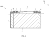
- the secondary battery includes a current collecting member 1, an electrode assembly 2, a housing 3, and a top cover assembly 4.
- the electrode assembly 2 is a core member of the secondary battery for implementing a charging and discharging function.
- the electrode assembly 2 includes a positive electrode plate, a negative electrode plate, and a separator, where the separator separates the positive electrode plate and the negative electrode plate.
- the electrode assembly 2 may be of a wound structure. Specifically, quantities of both the positive electrode plate and the negative electrode plate are one, and the positive electrode plate and the negative electrode plate are of a strip structure. The positive electrode plate, the separator, and the negative electrode plate are sequentially stacked and wound by two or more turns to form the electrode assembly 2. In preparation of the electrode assembly 2, the electrode assembly 2 may be first wound to form a hollow cylindrical structure. After the winding, the electrode assembly 2 is leveled to a plate shape.
- the electrode assembly 2 may alternatively be of a laminated structure. Specifically, there are a plurality of the positive electrode plates and a plurality of the negative electrode plates. The plurality of positive electrode plates and the negative electrode plates are alternately stacked, and the separator separates the positive electrode plates and the negative electrode plates.
- the positive electrode plate includes a positive electrode current collector and a positive active material layer coated on a surface of the positive electrode current collector.
- the positive electrode current collector may be an aluminum foil, and the positive active material layer includes a ternary material, lithium manganate, or lithium iron phosphate.
- the positive electrode current collector includes a positive electrode coating region and a positive electrode blank region, where a surface of the positive electrode coating region is coated with the positive active material layer, and a surface of the positive electrode blank region is not coated with the positive active material layer.
- the negative electrode plate includes a negative electrode current collector and a negative active material layer coated on a surface of the negative electrode current collector.
- the negative electrode current collector may be a copper foil, and the negative active material layer includes graphite or silicon.
- the negative electrode current collector includes a negative electrode coating region and a negative electrode blank region, where a surface of the negative electrode coating region is coated with the negative active material layer, and a surface of the negative electrode blank region is not coated with the negative active material layer.
- the electrode assembly 2 includes a base part 21 and a tab 22 and the tab 22 extends from an end of the base part 21 in a length direction X. There may be two tabs 22 extending from two ends of the base part 21 in the length direction X, respectively.
- the two tabs 22 are a positive electrode tab and a negative electrode tab.
- the base part 21 includes the separator, the positive electrode coating region, and the negative electrode coating region.
- the positive electrode tab includes the positive electrode blank region, and the negative electrode tab includes the negative electrode blank region.
- each tab 22 has a multilayer structure. Specifically, each tab 22 includes a plurality of tab layers stacked in a width direction Y
- the housing 3 may have a hexahedral shape or other shapes.
- An accommodating cavity is formed inside the housing 3 to accommodate the electrode assembly 2 and electrolyte.
- An end of the housing 3 along a height direction Z forms an opening, and the electrode assembly 2 can be placed into the accommodating cavity of the housing 3 through the opening.
- the housing 3 may be made of a conductive metal material, and preferably, the housing 3 is made of aluminum or aluminum alloy.
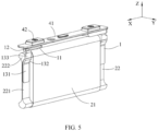
- the top cover assembly 4 includes a top cover plate 41 and an electrode terminal 42, where the top cover plate 41 is connected to the housing 3, and the electrode terminal 42 is disposed on the top cover plate 41.
- a shape of the top cover plate 41 matches that of the opening of the housing 3, and the top cover plate 41 may be connected to the housing 3 through welding or the like to cover the opening of the housing 3, thereby implementing sealing of the housing 3.
- the positive electrode terminal is electrically connected to the positive electrode tab
- the negative electrode terminal is electrically connected to the negative electrode tab.
- a current collecting member 1 of this application includes a terminal connection part 11, a transition part 12, and a tab connection part 13.
- the terminal connection part 11 is perpendicular to a height direction Z.
- the terminal connection part 11 may be connected to the electrode terminal 42 through welding, riveting, or the like.
- the terminal connection part 11 is plate-shaped, that is, in the height direction Z, the terminal connection part 11 has a uniform thickness.
- the transition part 12 is connected to the terminal connection part 11 and is bent to a side of the terminal connection part 11 along the height direction Z.
- the transition part 12 is bent to the side of the terminal connection part 11 away from a top cover assembly 4 along the height direction Z.
- a connection between the transition part 12 and the terminal connection part 11 extends along a first direction D, and the first direction D is inclined relative to a length direction X and a width direction Y
- a dimension of the secondary battery along the length direction X is larger than a dimension of the secondary battery along the width direction Y
- the tab connection part 13 is connected to the transition part 12 and is bent relative to the transition part 12, and a connection between the transition part 12 and the tab connection part 13 is parallel to the length direction X. Along the height direction Y, the tab connection part 13 is located on a side of the transition part 12 away from the terminal connection part 11.
- the tab connection part 13 may be connected to a tab 22 through welding or the like.
- the tab connection part 13 is at least partially perpendicular to the width direction Y In some embodiments, the tab connection part 13 is plate-shaped and is parallel to the length direction X.
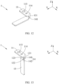
- the current collecting member 1 of this application is formed by bending a metal plate.
- the current collecting member 1 is formed based on the following steps: Referring to FIG. 11 , a strip-shaped metal plate is provided, where a dimension of the metal plate along the length direction X is larger than a dimension of the metal plate along the width direction Y
- the metal plate is bent to form a terminal connection part 11 and a flat plate part, where the flat plate part partially overlaps the terminal connection part 11 in the height direction Z, where a bending part of the metal plate is inclined relative to the length direction X and the width direction Y
- the flat plate part is bent downward along the height direction Z, and the transition part 12 and the tab connection part 13 are formed after the bending.
- the tab connection part 13 is perpendicular to the terminal connection part 11, the transition part 12 is connected between the terminal connection part 11 and tab connection part 13, and a connection between the transition part 12 and the tab connection part 13 is parallel to the length direction X.
- the tab 22 is substantially parallel to the length direction X. If the tab connection part 13 is perpendicular to the length direction X, when the electrode assembly 2 and the current collecting member 1 are assembled, only the tab 22 can be bent, or an end of the tab 22 away from a base part 21 is connected to the tab connection part 13. Bending the tab 22 increases processes and reduces assembly efficiency. In addition, the tab 22 is a metal foil, and therefore a thickness of each tab layer of the tab 22 is small. Connecting an end of each tab layer to the tab connection part 13 results in low connection strength and a small flow area.
- a bending structure of the current collecting member 1 of this application can make at least a portion of the tab connection part 13 perpendicular to the width direction Y, and the tab 22 can be directly attached to the portion of the tab connection part 13 perpendicular to the width direction Y without bending, thereby reducing assembly difficulty.
- a plurality of tab layers of the tab 22 can be laminated on the tab connection part 13, to increase a connection area between each tab layer and the tab connection part 13, enhance connection strength between the tab connection part 13 and the tab 22, and improve a flow capacity.
- a first edge 111 and a second edge 112 are oppositely arranged on two ends of the terminal connection part 11.
- the first edge 111 and the second edge 112 are parallel to the length direction X.
- a projection of the tab connection part 13 is at least partially located between a projection of the first edge 111 and a projection of the second edge 112. This can reduce an additional space occupied by the tab connection part 13 in the width direction Y, reduce a maximum dimension of the current collecting member 1 in the width direction Y, reduce a space occupied by the current collecting member 1 in the housing 3, and improve an energy density of the secondary battery.
- the transition part 12 includes a first bending part 121, an adapting part 122, and a second bending part 123, where the adapting part 122 is located on a lower side of the terminal connection part 11 along the height direction Z, the first bending part 121 is connected between the terminal connection part 11 and the adapting part 122 and is parallel to the first direction D, and the second bending part 123 is connected between the tab connection part 13 and the adapting part 122 and is parallel to the length direction X.
- the first bending part 121 and the second bending part 123 are respectively formed in two bending processes of the current collecting member 1, and an outer surface of the first bending part 121 and an outer surface of the second bending part 123 are generally arc.
- a projection of the second bending part 123 is at least partially located between the projection of the first edge 111 and the projection of the second edge 112. This can reduce an additional space occupied by the transition part 12 in the width direction Y, reduce a maximum dimension of the current collecting member 1 in the width direction Y, reduce a space occupied by the current collecting member 1 in the housing 3, and improve an energy density of the secondary battery.
- the adapting part 122 is located on an inner side the second bending part 123 in the width direction Y In a plane perpendicular to the height direction Z, along the width direction Y, the adapting part 122 is located between the projection of the first edge 111 and the projection of the second edge 112. In other words, the adapting part 122 does not occupy an additional space in the width direction Y
- the adapting part 122 is parallel to the terminal connection part 11. In this way, a gap between the adapting part 122 and the terminal connection part 11 can be reduced, and the dimension of the current collecting member 1 in the height direction Z can be reduced. Further preferably, the adapting part 122 contacts the terminal connection part 11; during charging and discharging, a current can be directly transmitted to the terminal connection part 11 through the adapting part 122, thereby increasing the flow area between the transition part 12 and the terminal connection part 121, and improving a flow capacity of the current collecting member 1.
- the current collecting member 1 has a first notch 14.
- the first notch 14 has a first sub-notch 141 and a second sub-notch 142, and the first sub-notch 141 and the second sub-notch 142 are communicated with each other.
- the first sub-notch 141 is located on a side of the first bending part 121 close to the tab connection part 13 along the first direction D, an included angle between the first direction D and the width direction Y is ⁇ , a dimension of the terminal connection part 11 along the width direction Y is L, and a dimension of the first bending part 121 along the first direction D is less than L/cos ⁇ .
- the end of the first bending part 121 close to the tab connection part 13 in the first direction D directly affects a position of the second bending part 123 in the width direction Y
- the space occupied by the second bending part 123 and the tab connection part 13 in the width direction Y can be reduced.
- the first bending part 121 and the tab connection part 13 do not occupy an additional space in the width direction Y In other words, in a plane perpendicular to the height direction Z, along the width direction Y, neither a projection of the second bending part 123 nor a projection of tab connection part 13 goes beyond the projection of the first edge 111 or the projection of the second edge 112.
- the second sub-notch 142 is located on a side of the second bending part 123 along the length direction X. Along the length direction X, a dimension of the tab connection part 13 is larger than a dimension of the second bending part 123.
- the included angle ⁇ between the first direction D and the width direction Y is 40 degrees to 50 degrees.
- the included angle ⁇ between the first direction D and the width direction Y is 45 degrees.
- the tab connection part 13 can be substantially parallel to the height direction Z, avoiding the tab connection part 13 being inclined relative to the height direction Z, and reducing the space occupied by the tab connection part 13.
- the included angle ⁇ between the first direction D and the width direction Y is 45 ⁇ 5 degrees.
- the manufacturing method includes the following steps.
- a metal plate is provided, where a dimension of the metal plate along a length direction X is larger than a dimension of the metal plate in a width direction Y, and the metal plate includes a first long side and a second long side that are oppositely arranged in the width direction Y
- a first notch 14 is opened on the first long side of the metal plate.
- the first notch 14 may be formed by punching or the like, and the first notch 14 may be rectangular, trapezoidal, triangular, semicircular, or the like.
- the metal plate is bent in a region in which the first notch 14 is opened, and a terminal connection part 11, a flat plate part, and a first bending part 121 are formed, where the flat plate part partially overlaps the terminal connection part 11 in a height direction Z, the first bending part 121 connects the terminal connection part 11 and the flat plate part, and the first bending part 121 extends along a first direction D inclined relative to the length direction X and the width direction Y
- first sub-notch 141 and a second sub-notch 142 that are communicated with each other are formed at the first notch 14.
- the first sub-notch 141 is opened on the first bending part 121.
- the first sub-notch 141 is opened on a side of the first bending part 121 along the first direction D.
- the second sub-notch 142 is opened on the flat plate part.
- the second sub-notch 142 is located on a side of a partial region of the flat plate part along the length direction X.
- the flat plate part is bent along the height direction Z, and an adapting part 122, a tab connection part 13, and the second bending part 123 are formed after the bending.
- the adapting part 122 is located on a lower side of the terminal connection part 11 along the height direction Z
- the tab connection part 13 is perpendicular to the adapting part 122
- the second bending part 123 is connected between the adapting part 122 and the tab connection part 13 and is parallel to the length direction X.
- the additional space occupied by the transition part 12 and the tab connection part 13 in the width direction Y can be reduced, the maximum dimension of the current collecting member 1 in the width direction Y can be reduced, and the space occupied by the current collecting member 1 in the housing 3 can be reduced.
- the current collecting member 1 further has a second notch 15, where the second notch 15 is at least partially located on a side of the first bending part 121 away from the tab connection part 13 along the first direction D.
- the dimension of the first bending part 121 along the first direction D can be reduced, so that an end of the first bending part 121 away from the tab connection part 13 in the first direction D tapers inwards.
- the additional space occupied by the first bending part 121 in the width direction Y can be reduced.
- a maximum dimension of the terminal connection part 11 in the width direction Y is a maximum dimension of the current collecting member 1 in the width direction Y
- neither a projection of the transition part 12 nor a projection of tab connection part 13 goes beyond the projection of the first edge 111 or the projection of the second edge 112.
- neither the transition part 12 nor the tab connection part 13 occupies the additional space in the width direction Y, thereby reducing the space occupied by the current collecting member 1 in the housing 3, and improving an energy density of the secondary battery.
- the manufacturing method includes the following steps.
- a metal plate is provided, where a dimension of the metal plate along a length direction X is larger than a dimension of the metal plate in a width direction Y, and the metal plate includes a first long side and a second long side that are oppositely arranged in the width direction Y
- a first notch 14 is opened on the first long side of the metal plate, and a second notch 15 is opened on the second long side of the metal plate.
- the first notch 14 and the second notch 15 may be formed in a same punching process, or may be formed in two punching processes, respectively.
- the metal plate is bent in a region in which the first notch 14 is opened, and a terminal connection part 11, a flat plate part, and a first bending part 121 are formed, where the flat plate part partially overlaps the terminal connection part 11 in a height direction Z, the first bending part 121 connects the terminal connection part 11 and the flat plate part, and the first bending part 121 extends along a first direction D inclined relative to the length direction X and the width direction Y
- a first sub-notch 141 and a second sub-notch 142 that are communicated with each other are formed at the first notch.
- the first sub-notch 141 is opened on the first bending part 121.
- the first sub-notch 141 is opened on a side of the first bending part 121 along the first direction D.
- the second sub-notch 142 is opened on the flat plate part.
- the second sub-notch 142 is located on a side of a partial region of the flat plate part along the length direction X.
- the second notch 15 is at least partially located on a side of the first bending part 121 away from the tab connection part 13 along the first direction D.
- the flat plate part is bent along the height direction Z, and an adapting part 122, a tab connection part 13, and the second bending part 123 are formed after the bending.
- the adapting part 122 is located on a lower side of the terminal connection part 11 along the height direction Z
- the tab connection part 13 is perpendicular to the adapting part 122
- the second bending part 123 is connected between the adapting part 122 and the tab connection part 13 and is parallel to the length direction X.
- a dimension of the terminal connection part 11 in the width direction Y is equal to a dimension of the tab connection part 13 in the length direction X.
- the current collecting member 1 of this application can be formed by a metal plate with equal widths through processes such as notch punching and bending.
- the tab 22 is arranged on a side of the tab connection part 13 along the width direction Y
- the tab connection part 13 includes a first part 131 and a second part 132, where the first part 131 is perpendicular to the width direction, the second part 132 is connected between the first part 131 and a transition part 12, and the second part 132 is inclined relative to the first part 131 toward a direction away from the tab 22. In a plane perpendicular to the height direction Z, a projection of the first part 131 at least partially overlaps a projection of the transition part 12.
- the tab 22 includes a fixing part 221 and a convex part 222, where the fixing part 221 is connected to the first part 131, and the convex part 222 is connected to the fixing part 221 and is located on a side of the fixing part 221 close to the transition part 12.
- the fixing part 221 may be connected to the first part 131 through welding or the like.
- the tab 22 is of a multi-layer structure, a plurality of tab layers of the tab 22 are gathered together in a middle region along the height direction Z and is connected to the first part 131, and the gathered middle region forms the fixing part 221.
- a convex part 222 is formed in an end region of the plurality of tab layers of the tab 22 in the height direction Z.
- a dimension of the convex part 222 is larger than a dimension of the fixing part 221.
- the second part 132 is inclined relative to the first part 131 toward a direction away from the tab 22, and therefore the second part 132 can reserve a specific space for the convex part 222 to accommodate the convex part 222 with a larger dimension.
- a portion of the convex part 222 is located between the second part 132 and the transition part 12.
- the tab connection part 13 further includes a third part 133, where the third part 133 is connected between the second part 132 and the transition part 12, and the third part 133 is perpendicular to the width direction Y In a plane perpendicular to the width direction Y, a projection of the third part 133 at least partially overlaps a projection of the convex part 222.
- the terminal connection part 11 has a first through hole 113 and a second through hole 114, where the first through hole 113 and the second through hole 114 are arranged along the length direction X.
- the top cover 41 has a terminal hole, and the first through hole 113 is provided on a lower side of the terminal hole.
- the electrode terminal 42 has a flange part and an extension part, where the flange part supports the terminal connection part 11 from the lower side, and the extension part extends from the flange part, passes through the first through hole 113 and the terminal hole, and extends outside of the top cover plate.
- the top cover assembly 4 further includes a lower insulator 43, where the lower insulator 43 is arranged on the top cover plate 41 and separates the top cover plate 41 from the current collecting member 1.
- the lower insulator 43 has a protrusion 431, where the protrusion 431 is inserted into the second through hole 114. The protrusion 431 can prevent the current collecting member 1 from rotating along the electrode terminal 42.
- this application also provides a method for manufacturing a current collecting member, including:
- the additional space occupied by the transition part 12 and the tab connection part 13 in the width direction Y can be reduced, the maximum dimension of the current collecting member 1 in the width direction Y can be reduced, and the space occupied by the current collecting member 1 in the housing 3 can be reduced.
- the method for manufacturing a current collecting member in this application further includes: opening a second notch 15 on the second long side of the metal plate, where the first notch 14 and the second notch 15 are respectively located on two sides of the metal plate along the width direction Y; after opening the first notch 14 and the second notch 15, bending the metal plate in a region in which the first notch 14 is opened, where after the metal plate is bent and the first bending part 121 is formed, the second notch 15 is at least partially located on a side of the first bending part 121 away from the tab connection part 13 along the first direction.
- the dimension of the first bending part 121 along the first direction D can be reduced, so that an end of the first bending part 121 away from the tab connection part 13 in the first direction D tapers inwards.
- the additional space occupied by the first bending part 121 in the width direction Y can be reduced.
- the method for manufacturing a current collecting member in this application further includes: after the tab connection part 13 is formed, bending the tab connection part 13 to form a first part 131 perpendicular to the adapting part 122, a third part 133 that is parallel to the first part 131 and that is connected to the second bending part 123, and a second part 132 that connects the first part 131 and the third part 133 and that is inclined relative to the first part 131.
- the bent tab connection part 13 can reserve a specific space for the convex part 222 to accommodate the convex part 222 with a larger dimension.
- This application further provides a method for manufacturing a secondary battery, including:
Landscapes
- Chemical & Material Sciences (AREA)
- Chemical Kinetics & Catalysis (AREA)
- Electrochemistry (AREA)
- General Chemical & Material Sciences (AREA)
- Engineering & Computer Science (AREA)
- Manufacturing & Machinery (AREA)
- Connection Of Batteries Or Terminals (AREA)
- Sealing Battery Cases Or Jackets (AREA)
Claims (12)
- Sekundärbatterie, umfassend: eine obere Abdeckungsanordnung (4), eine Elektrodenanordnung (2), ein Gehäuse (3) und ein Stromsammelglied (1), wobeidie Elektrodenanordnung (2) in dem Gehäuse (3) untergebracht ist und die Elektrodenanordnung (2) ein Basisteil (21) und eine Lasche (22) umfasst, wobei die Lasche (22) sich von einem Ende des Basisteils (21) in der Längsrichtung (X) erstreckt, wobei die Lasche (22) eine mehrschichtige Struktur aufweist und die Lasche (22) eine Vielzahl von Laschenschichten umfasst, die in einer Breitenrichtung (Y) gestapelt sind;die obere Abdeckungsanordnung (4) eine obere Abdeckungsplatte (41) und einen Elektrodenanschluss (42) umfasst, wobei die obere Abdeckungsplatte (41) mit dem Gehäuse (3) verbunden ist und der Elektrodenanschluss (42) auf der oberen Abdeckungsplatte (41) angeordnet ist;ein Anschlussverbindungsteil (11) des Stromsammelglieds (1) mit dem Elektrodenanschluss (42) verbunden ist und das Laschenverbindungsteil (13) des Stromsammelteils (1) mit der Lasche (22) verbunden ist; unddas Stromsammelteil (1) der Sekundärbatterie durch Biegen einer streifenförmigen Metallplatte gebildet ist und einen Anschlussverbindungsteil (11), einen Übergangsteil (12) und einen Laschenverbindungsteil (13) umfasst, wobeidas Anschlussverbindungsteil (11) senkrecht zu einer Höhenrichtung (Z) steht;der Übergangsteil (12) mit dem Anschlussverbindungsteil (11) verbunden ist und zu einer Seite des Anschlussverbindungsteils (11) entlang der Höhenrichtung (Z) gebogen ist, eine Verbindung zwischen dem Übergangsteil (12) und dem Anschlussverbindungsteil (11) sich entlang einer ersten Richtung (D) erstreckt und die erste Richtung (D) relativ zu einer Längenrichtung (X) und einer Breitenrichtung (Y) geneigt ist;der Laschenverbindungsteil (13) mit dem Übergangsteil (12) verbunden ist und relativ zum Übergangsteil (12) gebogen ist, und eine Verbindung zwischen dem Übergangsteil (12) und dem Laschenverbindungsteil (13) parallel zur Längsrichtung (X) ist;der Laschenverbindungsteil (13) zumindest teilweise senkrecht zur Breitenrichtung (Y) steht; undentlang der Höhenrichtung (Z) sich der Laschenverbindungsteil (13) auf einer Seite des Übergangsteils (12) befindet, die von dem Anschlussverbindungsteil (11) entfernt ist;wobei in der Breitenrichtung (Y) eine erste Kante (111) und eine zweite Kante (112) an zwei Enden des Anschlussverbindungsteils (11) einander gegenüberliegend angeordnet sind;in einer Ebene senkrecht zur Höhenrichtung (Z), entlang der Breitenrichtung (Y), ein Vorsprung des Laschenverbindungsteils (13) zumindest teilweise zwischen einem Vorsprung der ersten Kante (111) und einem Vorsprung der zweiten Kante (112) liegt; unddas Übergangsteil (12) ein erstes Biegeteil (121), ein Anpassungsteil (122) und ein zweites Biegeteil (123) umfasst, wobei das Anpassungsteil (122) an einer unteren Seite des Anschlussverbindungsteils (11) entlang der Höhenrichtung (Z) angeordnet ist, der erste Biegeteil (121) zwischen dem Anschlussverbindungsteil (11) und dem Anpassungsteil (122) verbunden ist und parallel zu der ersten Richtung (D) ist, und der zweite Biegeteil (123) zwischen dem Laschenverbindungsteil (13) und dem Anpassungsteil (122) verbunden ist und parallel zu der Längsrichtung (X) ist; undin einer Ebene senkrecht zur Höhenrichtung (Z), entlang der Breitenrichtung (Y), ein Vorsprung des zweiten Biegeteils (123) zumindest teilweise zwischen dem Vorsprung der ersten Kante (111) und dem Vorsprung der zweiten Kante (112) angeordnet ist.
- Sekundärbatterie nach Anspruch 1, wobei das Anpassungsteil (122) parallel zum Anschlussverbindungsteil (11) ist.
- Sekundärbatterie nach Anspruch 1, wobeidas Stromsammelglied (1) eine erste Kerbe (14) aufweist, die erste Kerbe (14) eine erste Unterkerbe (141) und eine zweite Unterkerbe (142) aufweist, und die erste Unterkerbe (141) und die zweite Unterkerbe (142) miteinander in Verbindung stehen, wobeidie erste Unterkerbe (141) auf einer Seite des ersten Biegeteils (121) nahe dem Laschenverbindungsteil (13) entlang der ersten Richtung (D) angeordnet ist, ein eingeschlossener Winkel zwischen der ersten Richtung (D) und der Breitenrichtung (Y) a ist, eine Abmessung des Endverbindungsteils (11) entlang der Breitenrichtung (Y) L ist, und eine Abmessung des ersten Biegeteils (121) entlang der ersten Richtung (D) kleiner als L/cos a ist;die zweite Unterkerbe (142) auf einer Seite des zweiten Biegeteils (123) entlang der Längsrichtung (X) angeordnet ist; undentlang der Längsrichtung (X) eine Abmessung des Laschenverbindungsteils (13) größer als eine Abmessung des zweiten Biegeteils (123) ist.
- Sekundärbatterie nach Anspruch 3, wobei der eingeschlossene Winkel zwischen der ersten Richtung (D) und der Breitenrichtung (Y) 40 Grad bis 50 Grad beträgt.
- Sekundärbatterie nach Anspruch 3, wobei das Stromabnehmerelement (1) ferner eine zweite Kerbe (15) aufweist und die zweite Kerbe (15) zumindest teilweise auf einer Seite des ersten Biegeteils (121) entfernt von dem Laschenverbindungsteil (13) entlang der ersten Richtung (D) angeordnet ist.
- Sekundärbatterie nach Anspruch 5, wobei eine maximale Abmessung des Anschlussverbindungsteils (11) in der Breitenrichtung (Y) eine maximale Abmessung des Stromsammelteils (1) in der Breitenrichtung (Y) ist.
- Sekundärbatterie nach einem der Ansprüche 1 bis 6, wobei eine Abmessung des Polanschlussteils (11) in der Breitenrichtung (Y) eine Abmessung des Laschenanschlussteils (13) in der Längenrichtung (X) ist.
- Sekundärbatterie nach einem der Ansprüche 1 bis 7,
wobeidie Lasche (22) auf einer Seite des Laschenverbindungsteils (13) entlang der Breitenrichtung (Y) angeordnet ist;der Laschenverbindungsteil (13) einen ersten Teil (131) und einen zweiten Teil (132) umfasst, wobei der erste Teil (13 I) senkrecht zur Breitenrichtung (Y) ist, der zweite Teil (132) zwischen dem ersten Teil (131) und einem Übergangsteil (12) verbunden ist, und der zweite Teil (132) relativ zum ersten Teil (131) in eine Richtung weg von der Lasche (22) geneigt ist;in einer Ebene senkrecht zur Höhenrichtung (Z), eine Projektion des ersten Teils (131) zumindest teilweise eine Projektion des Übergangsteils (12) überlappt;die Lasche (22) einen Befestigungsteil (221) und einen konvexen Teil (222) aufweist, wobei der Befestigungsteil (221) mit dem ersten Teil (131) verbunden ist und der konvexe Teil (222) mit dem Befestigungsteil (221) verbunden ist und auf einer Seite des Befestigungsteils (221) nahe dem Übergangsteil (12) angeordnet ist; und entlang der Breitenrichtung (Y) ist eine Abmessung des konvexen Teils (222) größer als eine Abmessung des Befestigungsteils (221); und in der Höhenrichtung (Z) sich ein Abschnitt des konvexen Teils (222) zwischen dem zweiten Teil (132) und dem Übergangsteil (12) befindet. - Sekundärbatterie nach Anspruch 8, wobeidas Laschenverbindungsteil (13) einen dritten Teil (133) umfasst, wobei der dritte Teil (133) zwischen dem zweiten Teil (132) und dem Übergangsteil (12) verbunden ist, und der dritte Teil (133) senkrecht zur Breitenrichtung (Y) verläuft; undin einer Ebene senkrecht zur Breitenrichtung (Y), eine Projektion des dritten Teils (133) zumindest teilweise eine Projektion des konvexen Teils (222) überlappt.
- Sekundärbatterie nach einem der Ansprüche 1 bis 7,
wobeidas Anschlussverbindungsteil (11) ein erstes Durchgangsloch (113) und ein zweites Durchgangsloch (114) aufweist, wobei das erste Durchgangsloch (113) und das zweite Durchgangsloch (114) entlang der Längsrichtung (X) angeordnet sind;der Elektrodenanschluss (42) durch das erste Durchgangsloch (113) verläuft;die obere Abdeckungsanordnung (4) ferner einen unteren Isolator (43) umfasst, wobei der untere Isolator (43) auf der oberen Abdeckungsplatte (41) angeordnet ist und die obere Abdeckungsplatte (41) von dem Stromabnahmeelement (1) trennt; undder untere Isolator (43) einen Vorsprung (431) aufweist, wobei der Vorsprung (431)
in das zweite Durchgangsloch (114) eingeführt ist. - Batteriemodul, umfassend die Sekundärbatterie nach einem der Ansprüche 1 bis 10, wobei mehrere Sekundärbatterien vorhanden sind.
- Gerät, umfassend einen Hauptkörper und die Sekundärbatterie nach einem der Ansprüche 1 bis 10, wobei mehrere Sekundärbatterien im Hauptkörper angeordnet sind.
Applications Claiming Priority (1)
| Application Number | Priority Date | Filing Date | Title |
|---|---|---|---|
| PCT/CN2019/122647 WO2021108980A1 (zh) | 2019-12-03 | 2019-12-03 | 集流构件及其制造方法、二次电池及其制造方法、电池模块和装置 |
Publications (3)
| Publication Number | Publication Date |
|---|---|
| EP3926751A1 EP3926751A1 (de) | 2021-12-22 |
| EP3926751A4 EP3926751A4 (de) | 2022-04-27 |
| EP3926751B1 true EP3926751B1 (de) | 2023-06-14 |
Family
ID=76221318
Family Applications (1)
| Application Number | Title | Priority Date | Filing Date |
|---|---|---|---|
| EP19954959.3A Active EP3926751B1 (de) | 2019-12-03 | 2019-12-03 | Sekundärbatterie mit spezifischem stromabnehmerelement, batteriemodul und vorrichtung |
Country Status (5)
| Country | Link |
|---|---|
| US (1) | US12315960B2 (de) |
| EP (1) | EP3926751B1 (de) |
| JP (1) | JP7411087B2 (de) |
| CN (1) | CN114144934B (de) |
| WO (1) | WO2021108980A1 (de) |
Families Citing this family (3)
| Publication number | Priority date | Publication date | Assignee | Title |
|---|---|---|---|---|
| WO2024098215A1 (zh) * | 2022-11-07 | 2024-05-16 | 宁德时代新能源科技股份有限公司 | 壳体、电池单体、电池和用电装置 |
| CN120261926B (zh) * | 2025-06-04 | 2025-08-26 | 中创新航科技集团股份有限公司 | 二次电池 |
| CN120709611B (zh) * | 2025-08-26 | 2026-01-06 | 宁德时代新能源科技股份有限公司 | 电池单体、电池装置和用电装置 |
Citations (1)
| Publication number | Priority date | Publication date | Assignee | Title |
|---|---|---|---|---|
| WO2012077216A1 (ja) * | 2010-12-09 | 2012-06-14 | 日立ビークルエナジー株式会社 | 二次電池 |
Family Cites Families (19)
| Publication number | Priority date | Publication date | Assignee | Title |
|---|---|---|---|---|
| GB1422782A (en) * | 1972-04-06 | 1976-01-28 | Alkaline Batteries Ltd | Alkaline electric cells |
| KR101049833B1 (ko) * | 2009-06-23 | 2011-07-15 | 에스비리모티브 주식회사 | 이차전지 |
| JP5656592B2 (ja) * | 2010-12-06 | 2015-01-21 | 日立オートモティブシステムズ株式会社 | 二次電池 |
| JP2012182043A (ja) * | 2011-03-02 | 2012-09-20 | Auto Network Gijutsu Kenkyusho:Kk | バスバー |
| JP2013127948A (ja) | 2011-11-17 | 2013-06-27 | Gs Yuasa Corp | 集電体、蓄電素子及び集電体の製造方法 |
| US20140023913A1 (en) * | 2012-07-17 | 2014-01-23 | Sanyo Electric Co., Ltd. | Prismatic secondary battery |
| US9620762B2 (en) * | 2013-02-01 | 2017-04-11 | Hitachi Automotive Systems, Ltd. | Electrical storage element |
| KR20140124247A (ko) * | 2013-04-16 | 2014-10-24 | 삼성에스디아이 주식회사 | 이차 전지 |
| JP6733175B2 (ja) | 2015-12-28 | 2020-07-29 | 株式会社Gsユアサ | 蓄電素子 |
| US11289746B2 (en) * | 2016-05-03 | 2022-03-29 | Bosch Battery Systems Llc | Cooling arrangement for an energy storage device |
| JP6870316B2 (ja) | 2016-12-21 | 2021-05-12 | 三洋電機株式会社 | 角形二次電池及びその製造方法 |
| KR101928073B1 (ko) * | 2016-12-27 | 2018-12-11 | 주식회사 유라코퍼레이션 | 버스바 어셈블리의 연결 구조 |
| CN207068966U (zh) * | 2017-06-23 | 2018-03-02 | 潍坊力神动力电池系统有限公司 | 一种动力电池模组软连接构件 |
| KR102571487B1 (ko) * | 2017-08-31 | 2023-08-28 | 삼성에스디아이 주식회사 | 이차 전지 및 그 조립 방법 |
| CN208014793U (zh) * | 2018-01-16 | 2018-10-26 | 宁德时代新能源科技股份有限公司 | 连接构件和充电电池 |
| CN207801088U (zh) * | 2018-01-31 | 2018-08-31 | 宁德时代新能源科技股份有限公司 | 汇流排以及电池模组 |
| CN208507745U (zh) * | 2018-07-13 | 2019-02-15 | 宁德时代新能源科技股份有限公司 | 二次电池 |
| DE112018008104B4 (de) | 2018-10-24 | 2026-03-26 | Kabushiki Kaisha Toshiba | Batterie und batteriepack |
| CN209675387U (zh) * | 2019-05-10 | 2019-11-22 | 昆山长盈精密技术有限公司 | 电极防护套 |
-
2019
- 2019-12-03 EP EP19954959.3A patent/EP3926751B1/de active Active
- 2019-12-03 CN CN201980098700.XA patent/CN114144934B/zh active Active
- 2019-12-03 JP JP2022533192A patent/JP7411087B2/ja active Active
- 2019-12-03 WO PCT/CN2019/122647 patent/WO2021108980A1/zh not_active Ceased
-
2021
- 2021-11-19 US US17/530,759 patent/US12315960B2/en active Active
Patent Citations (1)
| Publication number | Priority date | Publication date | Assignee | Title |
|---|---|---|---|---|
| WO2012077216A1 (ja) * | 2010-12-09 | 2012-06-14 | 日立ビークルエナジー株式会社 | 二次電池 |
Also Published As
| Publication number | Publication date |
|---|---|
| CN114144934A (zh) | 2022-03-04 |
| EP3926751A1 (de) | 2021-12-22 |
| US20220085465A1 (en) | 2022-03-17 |
| CN114144934B (zh) | 2024-03-15 |
| JP7411087B2 (ja) | 2024-01-10 |
| JP2023504667A (ja) | 2023-02-06 |
| US12315960B2 (en) | 2025-05-27 |
| WO2021108980A1 (zh) | 2021-06-10 |
| EP3926751A4 (de) | 2022-04-27 |
Similar Documents
| Publication | Publication Date | Title |
|---|---|---|
| KR102944814B1 (ko) | 이차전지 | |
| CN115836438B (zh) | 电池单体、电池、用电设备、电池单体的制造方法及设备 | |
| CN116349052B (zh) | 电池单体、电池、用电装置及制备电池单体的方法和设备 | |
| US12315960B2 (en) | Current collecting member and manufacturing method thereof, secondary battery and manufacturing method thereof, battery module, and apparatus | |
| KR100612236B1 (ko) | 이차 전지와 이에 사용되는 전극 조립체 | |
| US12469936B2 (en) | Battery cell, battery, and electric apparatus with tab including two different connecting portions | |
| US20240429504A1 (en) | Battery cell and manufacturing method therefor and battery | |
| EP4258445A1 (de) | Batterie, elektrische vorrichtung sowie verfahren und vorrichtung zur herstellung der batterie | |
| US20240088447A1 (en) | Electrode assembly, battery cell, battery and electrical device | |
| WO2023133859A1 (zh) | 电池单体及其制造方法、设备、电池及用电装置 | |
| US20250233289A1 (en) | Battery cell, battery, and electric device | |
| US20220247045A1 (en) | Electrode terminal and use thereof | |
| CN114361732A (zh) | 电化学装置及电子设备 | |
| CN100369296C (zh) | 蓄电池 | |
| EP4258437B1 (de) | Batterie und elektrische vorrichtung | |
| WO2024148474A1 (zh) | 电池的极片、电极组件、电池单体、电池和用电设备 | |
| KR20220048230A (ko) | 이차 전지 및 이를 포함하는 디바이스 | |
| US20250246708A1 (en) | Heat transfer device and secondary battery including the heat transfer device | |
| US20250046968A1 (en) | Secondary battery | |
| CN222995406U (zh) | 一种电芯极片、电芯、电池、电池包及用电设备 | |
| CN222927735U (zh) | 电池单体、电池、用电装置及储能装置 | |
| US20260031446A1 (en) | Battery cell, battery, and electric apparatus | |
| EP4593157A1 (de) | Wärmeübertragungsvorrichtung und sekundärbatterie mit der wärmeübertragungsvorrichtung | |
| EP4383386A1 (de) | Batteriezelle mit verbesserter wärmeübertragung | |
| KR20260050654A (ko) | 배터리 셀, 배터리 팩 및 이를 포함하는 자동차 |
Legal Events
| Date | Code | Title | Description |
|---|---|---|---|
| STAA | Information on the status of an ep patent application or granted ep patent |
Free format text: STATUS: THE INTERNATIONAL PUBLICATION HAS BEEN MADE |
|
| PUAI | Public reference made under article 153(3) epc to a published international application that has entered the european phase |
Free format text: ORIGINAL CODE: 0009012 |
|
| STAA | Information on the status of an ep patent application or granted ep patent |
Free format text: STATUS: REQUEST FOR EXAMINATION WAS MADE |
|
| 17P | Request for examination filed |
Effective date: 20210913 |
|
| AK | Designated contracting states |
Kind code of ref document: A1 Designated state(s): AL AT BE BG CH CY CZ DE DK EE ES FI FR GB GR HR HU IE IS IT LI LT LU LV MC MK MT NL NO PL PT RO RS SE SI SK SM TR |
|
| A4 | Supplementary search report drawn up and despatched |
Effective date: 20220324 |
|
| RIC1 | Information provided on ipc code assigned before grant |
Ipc: H01M 50/567 20210101ALI20220319BHEP Ipc: H01M 50/557 20210101ALI20220319BHEP Ipc: H01M 50/548 20210101ALI20220319BHEP Ipc: H01M 50/166 20210101ALI20220319BHEP Ipc: H01M 50/103 20210101ALI20220319BHEP Ipc: H01M 50/531 20210101AFI20220319BHEP |
|
| STAA | Information on the status of an ep patent application or granted ep patent |
Free format text: STATUS: EXAMINATION IS IN PROGRESS |
|
| 17Q | First examination report despatched |
Effective date: 20220818 |
|
| GRAP | Despatch of communication of intention to grant a patent |
Free format text: ORIGINAL CODE: EPIDOSNIGR1 |
|
| STAA | Information on the status of an ep patent application or granted ep patent |
Free format text: STATUS: GRANT OF PATENT IS INTENDED |
|
| INTG | Intention to grant announced |
Effective date: 20230127 |
|
| DAV | Request for validation of the european patent (deleted) | ||
| DAX | Request for extension of the european patent (deleted) | ||
| GRAS | Grant fee paid |
Free format text: ORIGINAL CODE: EPIDOSNIGR3 |
|
| GRAA | (expected) grant |
Free format text: ORIGINAL CODE: 0009210 |
|
| STAA | Information on the status of an ep patent application or granted ep patent |
Free format text: STATUS: THE PATENT HAS BEEN GRANTED |
|
| AK | Designated contracting states |
Kind code of ref document: B1 Designated state(s): AL AT BE BG CH CY CZ DE DK EE ES FI FR GB GR HR HU IE IS IT LI LT LU LV MC MK MT NL NO PL PT RO RS SE SI SK SM TR |
|
| REG | Reference to a national code |
Ref country code: CH Ref legal event code: EP |
|
| P01 | Opt-out of the competence of the unified patent court (upc) registered |
Effective date: 20230516 |
|
| REG | Reference to a national code |
Ref country code: DE Ref legal event code: R096 Ref document number: 602019031219 Country of ref document: DE |
|
| REG | Reference to a national code |
Ref country code: AT Ref legal event code: REF Ref document number: 1579908 Country of ref document: AT Kind code of ref document: T Effective date: 20230715 |
|
| REG | Reference to a national code |
Ref country code: LT Ref legal event code: MG9D |
|
| REG | Reference to a national code |
Ref country code: NL Ref legal event code: MP Effective date: 20230614 |
|
| PG25 | Lapsed in a contracting state [announced via postgrant information from national office to epo] |
Ref country code: SE Free format text: LAPSE BECAUSE OF FAILURE TO SUBMIT A TRANSLATION OF THE DESCRIPTION OR TO PAY THE FEE WITHIN THE PRESCRIBED TIME-LIMIT Effective date: 20230614 Ref country code: NO Free format text: LAPSE BECAUSE OF FAILURE TO SUBMIT A TRANSLATION OF THE DESCRIPTION OR TO PAY THE FEE WITHIN THE PRESCRIBED TIME-LIMIT Effective date: 20230914 Ref country code: ES Free format text: LAPSE BECAUSE OF FAILURE TO SUBMIT A TRANSLATION OF THE DESCRIPTION OR TO PAY THE FEE WITHIN THE PRESCRIBED TIME-LIMIT Effective date: 20230614 |
|
| REG | Reference to a national code |
Ref country code: AT Ref legal event code: MK05 Ref document number: 1579908 Country of ref document: AT Kind code of ref document: T Effective date: 20230614 |
|
| PG25 | Lapsed in a contracting state [announced via postgrant information from national office to epo] |
Ref country code: RS Free format text: LAPSE BECAUSE OF FAILURE TO SUBMIT A TRANSLATION OF THE DESCRIPTION OR TO PAY THE FEE WITHIN THE PRESCRIBED TIME-LIMIT Effective date: 20230614 Ref country code: NL Free format text: LAPSE BECAUSE OF FAILURE TO SUBMIT A TRANSLATION OF THE DESCRIPTION OR TO PAY THE FEE WITHIN THE PRESCRIBED TIME-LIMIT Effective date: 20230614 Ref country code: LV Free format text: LAPSE BECAUSE OF FAILURE TO SUBMIT A TRANSLATION OF THE DESCRIPTION OR TO PAY THE FEE WITHIN THE PRESCRIBED TIME-LIMIT Effective date: 20230614 Ref country code: LT Free format text: LAPSE BECAUSE OF FAILURE TO SUBMIT A TRANSLATION OF THE DESCRIPTION OR TO PAY THE FEE WITHIN THE PRESCRIBED TIME-LIMIT Effective date: 20230614 Ref country code: HR Free format text: LAPSE BECAUSE OF FAILURE TO SUBMIT A TRANSLATION OF THE DESCRIPTION OR TO PAY THE FEE WITHIN THE PRESCRIBED TIME-LIMIT Effective date: 20230614 Ref country code: GR Free format text: LAPSE BECAUSE OF FAILURE TO SUBMIT A TRANSLATION OF THE DESCRIPTION OR TO PAY THE FEE WITHIN THE PRESCRIBED TIME-LIMIT Effective date: 20230915 |
|
| PG25 | Lapsed in a contracting state [announced via postgrant information from national office to epo] |
Ref country code: FI Free format text: LAPSE BECAUSE OF FAILURE TO SUBMIT A TRANSLATION OF THE DESCRIPTION OR TO PAY THE FEE WITHIN THE PRESCRIBED TIME-LIMIT Effective date: 20230614 |
|
| PG25 | Lapsed in a contracting state [announced via postgrant information from national office to epo] |
Ref country code: SK Free format text: LAPSE BECAUSE OF FAILURE TO SUBMIT A TRANSLATION OF THE DESCRIPTION OR TO PAY THE FEE WITHIN THE PRESCRIBED TIME-LIMIT Effective date: 20230614 |
|
| PG25 | Lapsed in a contracting state [announced via postgrant information from national office to epo] |
Ref country code: IS Free format text: LAPSE BECAUSE OF FAILURE TO SUBMIT A TRANSLATION OF THE DESCRIPTION OR TO PAY THE FEE WITHIN THE PRESCRIBED TIME-LIMIT Effective date: 20231014 |
|
| PG25 | Lapsed in a contracting state [announced via postgrant information from national office to epo] |
Ref country code: SM Free format text: LAPSE BECAUSE OF FAILURE TO SUBMIT A TRANSLATION OF THE DESCRIPTION OR TO PAY THE FEE WITHIN THE PRESCRIBED TIME-LIMIT Effective date: 20230614 Ref country code: SK Free format text: LAPSE BECAUSE OF FAILURE TO SUBMIT A TRANSLATION OF THE DESCRIPTION OR TO PAY THE FEE WITHIN THE PRESCRIBED TIME-LIMIT Effective date: 20230614 Ref country code: RO Free format text: LAPSE BECAUSE OF FAILURE TO SUBMIT A TRANSLATION OF THE DESCRIPTION OR TO PAY THE FEE WITHIN THE PRESCRIBED TIME-LIMIT Effective date: 20230614 Ref country code: PT Free format text: LAPSE BECAUSE OF FAILURE TO SUBMIT A TRANSLATION OF THE DESCRIPTION OR TO PAY THE FEE WITHIN THE PRESCRIBED TIME-LIMIT Effective date: 20231016 Ref country code: IS Free format text: LAPSE BECAUSE OF FAILURE TO SUBMIT A TRANSLATION OF THE DESCRIPTION OR TO PAY THE FEE WITHIN THE PRESCRIBED TIME-LIMIT Effective date: 20231014 Ref country code: EE Free format text: LAPSE BECAUSE OF FAILURE TO SUBMIT A TRANSLATION OF THE DESCRIPTION OR TO PAY THE FEE WITHIN THE PRESCRIBED TIME-LIMIT Effective date: 20230614 Ref country code: CZ Free format text: LAPSE BECAUSE OF FAILURE TO SUBMIT A TRANSLATION OF THE DESCRIPTION OR TO PAY THE FEE WITHIN THE PRESCRIBED TIME-LIMIT Effective date: 20230614 Ref country code: AT Free format text: LAPSE BECAUSE OF FAILURE TO SUBMIT A TRANSLATION OF THE DESCRIPTION OR TO PAY THE FEE WITHIN THE PRESCRIBED TIME-LIMIT Effective date: 20230614 |
|
| PG25 | Lapsed in a contracting state [announced via postgrant information from national office to epo] |
Ref country code: PL Free format text: LAPSE BECAUSE OF FAILURE TO SUBMIT A TRANSLATION OF THE DESCRIPTION OR TO PAY THE FEE WITHIN THE PRESCRIBED TIME-LIMIT Effective date: 20230614 |
|
| REG | Reference to a national code |
Ref country code: DE Ref legal event code: R097 Ref document number: 602019031219 Country of ref document: DE |
|
| PLBE | No opposition filed within time limit |
Free format text: ORIGINAL CODE: 0009261 |
|
| STAA | Information on the status of an ep patent application or granted ep patent |
Free format text: STATUS: NO OPPOSITION FILED WITHIN TIME LIMIT |
|
| PG25 | Lapsed in a contracting state [announced via postgrant information from national office to epo] |
Ref country code: DK Free format text: LAPSE BECAUSE OF FAILURE TO SUBMIT A TRANSLATION OF THE DESCRIPTION OR TO PAY THE FEE WITHIN THE PRESCRIBED TIME-LIMIT Effective date: 20230614 |
|
| PG25 | Lapsed in a contracting state [announced via postgrant information from national office to epo] |
Ref country code: SI Free format text: LAPSE BECAUSE OF FAILURE TO SUBMIT A TRANSLATION OF THE DESCRIPTION OR TO PAY THE FEE WITHIN THE PRESCRIBED TIME-LIMIT Effective date: 20230614 |
|
| 26N | No opposition filed |
Effective date: 20240315 |
|
| PG25 | Lapsed in a contracting state [announced via postgrant information from national office to epo] |
Ref country code: SI Free format text: LAPSE BECAUSE OF FAILURE TO SUBMIT A TRANSLATION OF THE DESCRIPTION OR TO PAY THE FEE WITHIN THE PRESCRIBED TIME-LIMIT Effective date: 20230614 Ref country code: IT Free format text: LAPSE BECAUSE OF FAILURE TO SUBMIT A TRANSLATION OF THE DESCRIPTION OR TO PAY THE FEE WITHIN THE PRESCRIBED TIME-LIMIT Effective date: 20230614 |
|
| REG | Reference to a national code |
Ref country code: CH Ref legal event code: PL |
|
| REG | Reference to a national code |
Ref country code: DE Ref legal event code: R081 Ref document number: 602019031219 Country of ref document: DE Owner name: CONTEMPORARY AMPEREX TECHNOLOGY (HONG KONG) LI, HK Free format text: FORMER OWNER: CONTEMPORARY AMPEREX TECHNOLOGY CO., LIMITED, NINGDE, FUJIAN, CN |
|
| PG25 | Lapsed in a contracting state [announced via postgrant information from national office to epo] |
Ref country code: LU Free format text: LAPSE BECAUSE OF NON-PAYMENT OF DUE FEES Effective date: 20231203 |
|
| PG25 | Lapsed in a contracting state [announced via postgrant information from national office to epo] |
Ref country code: MC Free format text: LAPSE BECAUSE OF FAILURE TO SUBMIT A TRANSLATION OF THE DESCRIPTION OR TO PAY THE FEE WITHIN THE PRESCRIBED TIME-LIMIT Effective date: 20230614 |
|
| REG | Reference to a national code |
Ref country code: BE Ref legal event code: MM Effective date: 20231231 |
|
| PG25 | Lapsed in a contracting state [announced via postgrant information from national office to epo] |
Ref country code: MC Free format text: LAPSE BECAUSE OF FAILURE TO SUBMIT A TRANSLATION OF THE DESCRIPTION OR TO PAY THE FEE WITHIN THE PRESCRIBED TIME-LIMIT Effective date: 20230614 Ref country code: LU Free format text: LAPSE BECAUSE OF NON-PAYMENT OF DUE FEES Effective date: 20231203 |
|
| REG | Reference to a national code |
Ref country code: GB Ref legal event code: 732E Free format text: REGISTERED BETWEEN 20240829 AND 20240904 |
|
| REG | Reference to a national code |
Ref country code: IE Ref legal event code: MM4A |
|
| PG25 | Lapsed in a contracting state [announced via postgrant information from national office to epo] |
Ref country code: IE Free format text: LAPSE BECAUSE OF NON-PAYMENT OF DUE FEES Effective date: 20231203 |
|
| PG25 | Lapsed in a contracting state [announced via postgrant information from national office to epo] |
Ref country code: BE Free format text: LAPSE BECAUSE OF NON-PAYMENT OF DUE FEES Effective date: 20231231 |
|
| PG25 | Lapsed in a contracting state [announced via postgrant information from national office to epo] |
Ref country code: CH Free format text: LAPSE BECAUSE OF NON-PAYMENT OF DUE FEES Effective date: 20231231 |
|
| PG25 | Lapsed in a contracting state [announced via postgrant information from national office to epo] |
Ref country code: IE Free format text: LAPSE BECAUSE OF NON-PAYMENT OF DUE FEES Effective date: 20231203 Ref country code: CH Free format text: LAPSE BECAUSE OF NON-PAYMENT OF DUE FEES Effective date: 20231231 Ref country code: BE Free format text: LAPSE BECAUSE OF NON-PAYMENT OF DUE FEES Effective date: 20231231 |
|
| PG25 | Lapsed in a contracting state [announced via postgrant information from national office to epo] |
Ref country code: BG Free format text: LAPSE BECAUSE OF FAILURE TO SUBMIT A TRANSLATION OF THE DESCRIPTION OR TO PAY THE FEE WITHIN THE PRESCRIBED TIME-LIMIT Effective date: 20230614 |
|
| PG25 | Lapsed in a contracting state [announced via postgrant information from national office to epo] |
Ref country code: BG Free format text: LAPSE BECAUSE OF FAILURE TO SUBMIT A TRANSLATION OF THE DESCRIPTION OR TO PAY THE FEE WITHIN THE PRESCRIBED TIME-LIMIT Effective date: 20230614 |
|
| PG25 | Lapsed in a contracting state [announced via postgrant information from national office to epo] |
Ref country code: CY Free format text: LAPSE BECAUSE OF FAILURE TO SUBMIT A TRANSLATION OF THE DESCRIPTION OR TO PAY THE FEE WITHIN THE PRESCRIBED TIME-LIMIT; INVALID AB INITIO Effective date: 20191203 |
|
| PG25 | Lapsed in a contracting state [announced via postgrant information from national office to epo] |
Ref country code: HU Free format text: LAPSE BECAUSE OF FAILURE TO SUBMIT A TRANSLATION OF THE DESCRIPTION OR TO PAY THE FEE WITHIN THE PRESCRIBED TIME-LIMIT; INVALID AB INITIO Effective date: 20191203 |
|
| PG25 | Lapsed in a contracting state [announced via postgrant information from national office to epo] |
Ref country code: TR Free format text: LAPSE BECAUSE OF FAILURE TO SUBMIT A TRANSLATION OF THE DESCRIPTION OR TO PAY THE FEE WITHIN THE PRESCRIBED TIME-LIMIT Effective date: 20230614 |
|
| PGFP | Annual fee paid to national office [announced via postgrant information from national office to epo] |
Ref country code: DE Payment date: 20251212 Year of fee payment: 7 |
|
| PGFP | Annual fee paid to national office [announced via postgrant information from national office to epo] |
Ref country code: GB Payment date: 20251211 Year of fee payment: 7 |
|
| PGFP | Annual fee paid to national office [announced via postgrant information from national office to epo] |
Ref country code: FR Payment date: 20251212 Year of fee payment: 7 |