EP4383386A1 - Batteriezelle mit verbesserter wärmeübertragung - Google Patents
Batteriezelle mit verbesserter wärmeübertragung Download PDFInfo
- Publication number
- EP4383386A1 EP4383386A1 EP22212540.3A EP22212540A EP4383386A1 EP 4383386 A1 EP4383386 A1 EP 4383386A1 EP 22212540 A EP22212540 A EP 22212540A EP 4383386 A1 EP4383386 A1 EP 4383386A1
- Authority
- EP
- European Patent Office
- Prior art keywords
- vertical edge
- cell
- battery cell
- casing
- cell casing
- Prior art date
- Legal status (The legal status is an assumption and is not a legal conclusion. Google has not performed a legal analysis and makes no representation as to the accuracy of the status listed.)
- Pending
Links
Images

Classifications
-
- H—ELECTRICITY
- H01—ELECTRIC ELEMENTS
- H01M—PROCESSES OR MEANS, e.g. BATTERIES, FOR THE DIRECT CONVERSION OF CHEMICAL ENERGY INTO ELECTRICAL ENERGY
- H01M50/00—Constructional details or processes of manufacture of the non-active parts of electrochemical cells other than fuel cells, e.g. hybrid cells
- H01M50/10—Primary casings; Jackets or wrappings
- H01M50/102—Primary casings; Jackets or wrappings characterised by their shape or physical structure
- H01M50/103—Primary casings; Jackets or wrappings characterised by their shape or physical structure prismatic or rectangular
-
- H—ELECTRICITY
- H01—ELECTRIC ELEMENTS
- H01M—PROCESSES OR MEANS, e.g. BATTERIES, FOR THE DIRECT CONVERSION OF CHEMICAL ENERGY INTO ELECTRICAL ENERGY
- H01M50/00—Constructional details or processes of manufacture of the non-active parts of electrochemical cells other than fuel cells, e.g. hybrid cells
- H01M50/10—Primary casings; Jackets or wrappings
- H01M50/172—Arrangements of electric connectors penetrating the casing
- H01M50/174—Arrangements of electric connectors penetrating the casing adapted for the shape of the cells
- H01M50/179—Arrangements of electric connectors penetrating the casing adapted for the shape of the cells for cells having curved cross-section, e.g. round or elliptic
-
- H—ELECTRICITY
- H01—ELECTRIC ELEMENTS
- H01M—PROCESSES OR MEANS, e.g. BATTERIES, FOR THE DIRECT CONVERSION OF CHEMICAL ENERGY INTO ELECTRICAL ENERGY
- H01M10/00—Secondary cells; Manufacture thereof
- H01M10/60—Heating or cooling; Temperature control
- H01M10/65—Means for temperature control structurally associated with the cells
- H01M10/653—Means for temperature control structurally associated with the cells characterised by electrically insulating or thermally conductive materials
-
- H—ELECTRICITY
- H01—ELECTRIC ELEMENTS
- H01M—PROCESSES OR MEANS, e.g. BATTERIES, FOR THE DIRECT CONVERSION OF CHEMICAL ENERGY INTO ELECTRICAL ENERGY
- H01M10/00—Secondary cells; Manufacture thereof
- H01M10/04—Construction or manufacture in general
- H01M10/0431—Cells with wound or folded electrodes
-
- H—ELECTRICITY
- H01—ELECTRIC ELEMENTS
- H01M—PROCESSES OR MEANS, e.g. BATTERIES, FOR THE DIRECT CONVERSION OF CHEMICAL ENERGY INTO ELECTRICAL ENERGY
- H01M10/00—Secondary cells; Manufacture thereof
- H01M10/05—Accumulators with non-aqueous electrolyte
- H01M10/058—Construction or manufacture
- H01M10/0587—Construction or manufacture of accumulators having only wound construction elements, i.e. wound positive electrodes, wound negative electrodes and wound separators
-
- H—ELECTRICITY
- H01—ELECTRIC ELEMENTS
- H01M—PROCESSES OR MEANS, e.g. BATTERIES, FOR THE DIRECT CONVERSION OF CHEMICAL ENERGY INTO ELECTRICAL ENERGY
- H01M10/00—Secondary cells; Manufacture thereof
- H01M10/60—Heating or cooling; Temperature control
- H01M10/61—Types of temperature control
- H01M10/613—Cooling or keeping cold
-
- H—ELECTRICITY
- H01—ELECTRIC ELEMENTS
- H01M—PROCESSES OR MEANS, e.g. BATTERIES, FOR THE DIRECT CONVERSION OF CHEMICAL ENERGY INTO ELECTRICAL ENERGY
- H01M10/00—Secondary cells; Manufacture thereof
- H01M10/60—Heating or cooling; Temperature control
- H01M10/62—Heating or cooling; Temperature control specially adapted for specific applications
- H01M10/625—Vehicles
-
- H—ELECTRICITY
- H01—ELECTRIC ELEMENTS
- H01M—PROCESSES OR MEANS, e.g. BATTERIES, FOR THE DIRECT CONVERSION OF CHEMICAL ENERGY INTO ELECTRICAL ENERGY
- H01M10/00—Secondary cells; Manufacture thereof
- H01M10/60—Heating or cooling; Temperature control
- H01M10/64—Heating or cooling; Temperature control characterised by the shape of the cells
- H01M10/643—Cylindrical cells
-
- H—ELECTRICITY
- H01—ELECTRIC ELEMENTS
- H01M—PROCESSES OR MEANS, e.g. BATTERIES, FOR THE DIRECT CONVERSION OF CHEMICAL ENERGY INTO ELECTRICAL ENERGY
- H01M10/00—Secondary cells; Manufacture thereof
- H01M10/60—Heating or cooling; Temperature control
- H01M10/65—Means for temperature control structurally associated with the cells
- H01M10/654—Means for temperature control structurally associated with the cells located inside the innermost case of the cells, e.g. mandrels, electrodes or electrolytes
-
- H—ELECTRICITY
- H01—ELECTRIC ELEMENTS
- H01M—PROCESSES OR MEANS, e.g. BATTERIES, FOR THE DIRECT CONVERSION OF CHEMICAL ENERGY INTO ELECTRICAL ENERGY
- H01M4/00—Electrodes
- H01M4/02—Electrodes composed of, or comprising, active material
- H01M4/13—Electrodes for accumulators with non-aqueous electrolyte, e.g. for lithium-accumulators; Processes of manufacture thereof
-
- H—ELECTRICITY
- H01—ELECTRIC ELEMENTS
- H01M—PROCESSES OR MEANS, e.g. BATTERIES, FOR THE DIRECT CONVERSION OF CHEMICAL ENERGY INTO ELECTRICAL ENERGY
- H01M50/00—Constructional details or processes of manufacture of the non-active parts of electrochemical cells other than fuel cells, e.g. hybrid cells
- H01M50/50—Current conducting connections for cells or batteries
- H01M50/528—Fixed electrical connections, i.e. not intended for disconnection
-
- H—ELECTRICITY
- H01—ELECTRIC ELEMENTS
- H01M—PROCESSES OR MEANS, e.g. BATTERIES, FOR THE DIRECT CONVERSION OF CHEMICAL ENERGY INTO ELECTRICAL ENERGY
- H01M50/00—Constructional details or processes of manufacture of the non-active parts of electrochemical cells other than fuel cells, e.g. hybrid cells
- H01M50/50—Current conducting connections for cells or batteries
- H01M50/531—Electrode connections inside a battery casing
- H01M50/533—Electrode connections inside a battery casing characterised by the shape of the leads or tabs
-
- H—ELECTRICITY
- H01—ELECTRIC ELEMENTS
- H01M—PROCESSES OR MEANS, e.g. BATTERIES, FOR THE DIRECT CONVERSION OF CHEMICAL ENERGY INTO ELECTRICAL ENERGY
- H01M50/00—Constructional details or processes of manufacture of the non-active parts of electrochemical cells other than fuel cells, e.g. hybrid cells
- H01M50/50—Current conducting connections for cells or batteries
- H01M50/543—Terminals
- H01M50/545—Terminals formed by the casing of the cells
-
- H—ELECTRICITY
- H01—ELECTRIC ELEMENTS
- H01M—PROCESSES OR MEANS, e.g. BATTERIES, FOR THE DIRECT CONVERSION OF CHEMICAL ENERGY INTO ELECTRICAL ENERGY
- H01M4/00—Electrodes
- H01M4/02—Electrodes composed of, or comprising, active material
- H01M2004/026—Electrodes composed of, or comprising, active material characterised by the polarity
- H01M2004/027—Negative electrodes
-
- H—ELECTRICITY
- H01—ELECTRIC ELEMENTS
- H01M—PROCESSES OR MEANS, e.g. BATTERIES, FOR THE DIRECT CONVERSION OF CHEMICAL ENERGY INTO ELECTRICAL ENERGY
- H01M2220/00—Batteries for particular applications
- H01M2220/20—Batteries in motive systems, e.g. vehicle, ship, plane
-
- Y—GENERAL TAGGING OF NEW TECHNOLOGICAL DEVELOPMENTS; GENERAL TAGGING OF CROSS-SECTIONAL TECHNOLOGIES SPANNING OVER SEVERAL SECTIONS OF THE IPC; TECHNICAL SUBJECTS COVERED BY FORMER USPC CROSS-REFERENCE ART COLLECTIONS [XRACs] AND DIGESTS
- Y02—TECHNOLOGIES OR APPLICATIONS FOR MITIGATION OR ADAPTATION AGAINST CLIMATE CHANGE
- Y02E—REDUCTION OF GREENHOUSE GAS [GHG] EMISSIONS, RELATED TO ENERGY GENERATION, TRANSMISSION OR DISTRIBUTION
- Y02E60/00—Enabling technologies; Technologies with a potential or indirect contribution to GHG emissions mitigation
- Y02E60/10—Energy storage using batteries
-
- Y—GENERAL TAGGING OF NEW TECHNOLOGICAL DEVELOPMENTS; GENERAL TAGGING OF CROSS-SECTIONAL TECHNOLOGIES SPANNING OVER SEVERAL SECTIONS OF THE IPC; TECHNICAL SUBJECTS COVERED BY FORMER USPC CROSS-REFERENCE ART COLLECTIONS [XRACs] AND DIGESTS
- Y02—TECHNOLOGIES OR APPLICATIONS FOR MITIGATION OR ADAPTATION AGAINST CLIMATE CHANGE
- Y02P—CLIMATE CHANGE MITIGATION TECHNOLOGIES IN THE PRODUCTION OR PROCESSING OF GOODS
- Y02P70/00—Climate change mitigation technologies in the production process for final industrial or consumer products
- Y02P70/50—Manufacturing or production processes characterised by the final manufactured product
Definitions
- the disclosure relates generally to a battery cell.
- the disclosure relates to a cylindrical or prismatic battery cell with improved heat transfer.
- the disclosure can be applied in any application using a battery cell, but in particular in vehicles, such as electrical vehicles and heavy-duty vehicles, such as trucks, buses, and construction equipment.
- Prismatic cells may also have a stacked electrode assembly configuration.
- the battery cells are usually cooled down by applying cooling to the cell casing. Since the heat is generated within the cell, this cooling takes a long time as heat transfer in a radial direction is much slower compared to heat transfer in a plane direction.
- the heat generated in the electrode assembly must be removed since otherwise the battery cell may become overheated, age too quickly or create safety hazards or loose efficiency too quickly. There is thus a need for a new and improved cell design for a cylindrical and prismatic battery cell.
- a battery cell comprising a cell casing, and an electrode assembly comprising a negative electrode and a positive electrode, and at least two insulating layers in a sandwich configuration, wherein said negative electrode comprises a current collector and a negative electrode material coating arranged thereon, and has an outer vertical edge extending along a vertical axis, and which is facing said cell casing, wherein said outer vertical edge is attached to said cell casing by at least 80 % of the length of the vertical edge.
- the first aspect of the disclosure may seek to provide for a reduced cell aging with time and usage.
- a technical benefit may include improved and more efficient cooling of the inside of the cell by means of heat conduction.
- By attaching the edge of the negative electrode to the cell casing an increased surface area for heat transfer between the cell casing and the inside of the electrode assembly is achieved, through the direct cooling of the negative electrode. This means that the cooling of the body or can of the battery cell will be more efficiently transferred to the inside of the battery cell, and this may reduce ageing effects, improve the function and life-time of the battery cell.
- the vertical edge of said current collector may be attached to said cell casing.
- a technical benefit may include a more efficient heat transfer through the current collector, which often is a copper foil.
- said vertical edge of said current collector may have a reinforced portion arranged along the length of the vertical edge.
- reinforced portion is meant that the current collector is thicker at the edge portion.
- a technical benefit of the reinforced edge may include ensuring that the attachment to the cell casing is stable and does not break.
- said outer vertical edge may be attached to said cell casing by at least 90 %, or at least 95 %, or at least 99 % of the length of the vertical edge.
- a technical benefit of attaching substantially the complete edge of the edge to the cell casing is that the heat efficient transfer and cooling is ensured.
- the battery cell according to the first aspect further may comprise a soldered portion arranged between said vertical edge and said cell casing.
- the soldered portion ensures the connection between the cell casing and the electrode.
- the soldered portion may comprise a material having a thermal conductivity in the range of 50 to 400 W/m ⁇ K.
- Conventional soldering materials, such as tin has a thermal conductivity around 50 W/m K.
- the soldering portion or the soldering material used in the present disclosure is preferably formed by a material with a thermal conductivity in the higher range, and the technical benefit may include an increase in the heat transfer and cooling.
- a vehicle comprising the battery cell according to the first aspect.
- the second aspect of the disclosure may seek to provide a vehicle comprising a battery pack with an improved life-time, which is beneficial from both an environmental and sustainability aspect.
- a method for manufacturing a battery cell comprising: providing a cell casing; providing an electrode assembly comprising a negative electrode, a positive electrode, and at least two insulating layers in a sandwich configuration, and wherein said negative electrode comprises a current collector and a negative electrode material coated thereon; placing said electrode assembly into said cell casing and attaching an outer vertical edge of said negative electrode to said cell casing, wherein said outer vertical edge is attached to cell casing by at least 80 % of the length of the vertical edge.
- the third aspect of the disclosure may seek to provide for a reduced cell aging with time and usage.
- the method may further comprise arranging said electrode assembly to form a rolled-up sandwich configuration before placing said rolled-up sandwich configuration into said cell casing.
- the method may further comprise arranging said electrode assembly to form a stacked configuration, before placing said stacked configuration into said cell casing.
- said vertical edge may be attached to the cell casing by at least 90 %, or at least 95 % or at least 99 % of the length of the vertical edge.
- a technical benefit of attaching substantially the complete edge of the edge to the cell casing is that the heat efficient transfer and cooling is ensured.
- a vertical edge of said current collector may be attached to said cell casing.
- said vertical edge may be attached to said cell casing by soldering, such that a soldered portion is formed between said vertical edge and said cell casing.
- the technical benefit of the soldered portion may include ensuring that the connection between the cell casing and the electrode is stable.
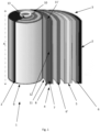
- the electrode assembly 3 comprises a negative electrode 4 and a positive electrode 5, and insulating layers 6, 6' arranged in a sandwich configuration.
- the electrode assembly 3 is rolled-up into a so called jelly-roll or Swiss roll assembly.
- the rolled-up assembly or configuration 3' is placed in the cell casing 2 to form a cylindrical battery cell 1. This type of configuration can also be seen in a prismatic cell (not shown).
- the negative electrode or anode 4 has two opposing longitudinal edges 11, 11' and two opposing vertical edges 12. Only the outer vertical edge 12 is showing in Fig. 1 as the opposing vertical edge is arranged at the center portion 13 of the rolled-up electrode assembly 3.
- the vertical edge 12 extends along a vertical axis A, i.e. along the length of the cylindrical battery cell.
- the longitudinal edges 11, 11' are arranged such that it is facing the top portion 10 and bottom portion 9 of the cell casing 2 respectively.
- the outer vertical edge 12 may according to one alternative be attached to the cell casing 2, by at least 90 % of the vertical edge.
- the vertical edge 12 may be attached to the casing 2 by soldering the outer vertical edge 12 to the casing.
- a soldered portion (not shown in Fig. 1 ) may thus be formed between the casing 2 and the outer vertical edge 12.
- a vertical edge 12 of the current collector 8 of the negative electrode 4 in a jelly-roll configuration 3' may be attached to the cell casing 2 of a cylindrical or prismatic battery cell.
- the current collector 8 (or the conductive substrate) may thus have an uncoated or extended portion which is attached to the cell casing.
- Example 1 A battery cell 1 comprising a cell casing 2, and an electrode assembly 3 comprising a negative electrode 4 and a positive electrode 5, and at least two insulating layers 6, 6' in a sandwich configuration, wherein said negative electrode 4 comprises a current collector 7 and a negative electrode material 8 coating arranged thereon, and has an outer vertical edge 12 extending along a vertical axis A, and which is facing said cell casing 2, wherein said outer vertical edge 12 is attached to said cell casing 2 by at least 80 % of the length of the vertical edge.
- Example 2 The battery cell 1 according to the example 1, wherein a vertical edge 12 of said current collector 7 is attached to said cell casing 2.
- Example 3 The battery cell 1 according to example 1 or 2, wherein said vertical edge 12 of said current collector 7 has a reinforced portion arranged along the length of the vertical edge.
- Example 6 The battery cell according to any one of examples 1 to 3, wherein said outer vertical edge 12 is attached to said cell casing 2 by at least 99 % of the length of the vertical edge.
- Example 8 The battery cell of example 7, wherein said soldered portion comprises a material having a thermal conductivity in the range of 50 to 400 W/m ⁇ K.
- Example 9 The battery cell according to any one of examples 1 to 8, wherein said battery cell is any one of a cylindrical battery cell and a prismatic battery cell.
- Example 10 A vehicle comprising the battery cell according to any of examples 1-9.
- Example 11 A method for manufacturing a battery cell 1 according to any one of examples 1 to 9, comprising: providing a cell casing 2; providing an electrode assembly 3 comprising a negative electrode 4, a positive electrode 5, and at least two insulating layers 6, 6' in a sandwich configuration, and wherein said negative electrode 4 comprises a current collector 7 and a negative electrode material 8 coated thereon; placing said electrode assembly 3 into said cell casing 2; and attaching an outer vertical edge 7 of said negative electrode 4 to said cell casing 2, wherein said outer vertical edge 12 is attached to cell casing 2 by at least 80 % of the length of the vertical edge 12.
- Example 12 The method for manufacturing said battery cell 1 according to example 11, wherein the method further comprises: arranging said electrode assembly to form a rolled-up sandwich configuration 3' before placing said rolled-up sandwich configuration 3' into said cell casing 2.
- Example 13 The method for manufacturing said battery cell 1 according to claim 11, wherein the method further comprises: arranging said electrode assembly to form a stacked configuration 14, before placing said stacked configuration into said cell casing 2.
- Example 19 The method for manufacturing a battery cell 1 according to any one of examples 11 to 18, wherein said vertical edge 12 is attached to said cell casing 2 by soldering such that a soldered portion is formed between said vertical edge 12 and said cell casing.
- Example 20 The method for manufacturing a battery cell 1 according to example 19, wherein said soldered portion comprises a material having a thermal conductivity in the range of 50 to 400 W/m K.
- Relative terms such as “below” or “above” or “upper” or “lower” or “horizontal” or “vertical” may be used herein to describe a relationship of one element to another element as illustrated in the Figures. It will be understood that these terms and those discussed above are intended to encompass different orientations of the device in addition to the orientation depicted in the Figures. It will be understood that when an element is referred to as being “connected” or “coupled” to another element, it can be directly connected or coupled to the other element, or intervening elements may be present. In contrast, when an element is referred to as being “directly connected” or “directly coupled” to another element, there are no intervening elements present.
Landscapes
- Chemical & Material Sciences (AREA)
- Chemical Kinetics & Catalysis (AREA)
- Electrochemistry (AREA)
- General Chemical & Material Sciences (AREA)
- Engineering & Computer Science (AREA)
- Manufacturing & Machinery (AREA)
- Materials Engineering (AREA)
- Sealing Battery Cases Or Jackets (AREA)
- Secondary Cells (AREA)
Priority Applications (3)
| Application Number | Priority Date | Filing Date | Title |
|---|---|---|---|
| EP22212540.3A EP4383386A1 (de) | 2022-12-09 | 2022-12-09 | Batteriezelle mit verbesserter wärmeübertragung |
| US18/515,959 US20240194970A1 (en) | 2022-12-09 | 2023-11-21 | Battery cell with improved heat transfer |
| CN202311572527.7A CN118173952A (zh) | 2022-12-09 | 2023-11-23 | 具有改进的热传递的电池单体 |
Applications Claiming Priority (1)
| Application Number | Priority Date | Filing Date | Title |
|---|---|---|---|
| EP22212540.3A EP4383386A1 (de) | 2022-12-09 | 2022-12-09 | Batteriezelle mit verbesserter wärmeübertragung |
Publications (1)
| Publication Number | Publication Date |
|---|---|
| EP4383386A1 true EP4383386A1 (de) | 2024-06-12 |
Family
ID=84487842
Family Applications (1)
| Application Number | Title | Priority Date | Filing Date |
|---|---|---|---|
| EP22212540.3A Pending EP4383386A1 (de) | 2022-12-09 | 2022-12-09 | Batteriezelle mit verbesserter wärmeübertragung |
Country Status (3)
| Country | Link |
|---|---|
| US (1) | US20240194970A1 (de) |
| EP (1) | EP4383386A1 (de) |
| CN (1) | CN118173952A (de) |
Citations (4)
| Publication number | Priority date | Publication date | Assignee | Title |
|---|---|---|---|---|
| JP2001068145A (ja) * | 1999-08-30 | 2001-03-16 | Toshiba Battery Co Ltd | 角形アルカリ二次電池 |
| US7108942B1 (en) * | 2003-03-27 | 2006-09-19 | Wilson Greatbatch Technologies, Inc. | Efficient electrode assembly design for cells with alkali metal anodes |
| WO2012042830A1 (ja) * | 2010-09-30 | 2012-04-05 | パナソニック株式会社 | 非水電解質二次電池 |
| WO2022044936A1 (ja) * | 2020-08-28 | 2022-03-03 | 三洋電機株式会社 | 二次電池 |
-
2022
- 2022-12-09 EP EP22212540.3A patent/EP4383386A1/de active Pending
-
2023
- 2023-11-21 US US18/515,959 patent/US20240194970A1/en active Pending
- 2023-11-23 CN CN202311572527.7A patent/CN118173952A/zh active Pending
Patent Citations (4)
| Publication number | Priority date | Publication date | Assignee | Title |
|---|---|---|---|---|
| JP2001068145A (ja) * | 1999-08-30 | 2001-03-16 | Toshiba Battery Co Ltd | 角形アルカリ二次電池 |
| US7108942B1 (en) * | 2003-03-27 | 2006-09-19 | Wilson Greatbatch Technologies, Inc. | Efficient electrode assembly design for cells with alkali metal anodes |
| WO2012042830A1 (ja) * | 2010-09-30 | 2012-04-05 | パナソニック株式会社 | 非水電解質二次電池 |
| WO2022044936A1 (ja) * | 2020-08-28 | 2022-03-03 | 三洋電機株式会社 | 二次電池 |
Also Published As
| Publication number | Publication date |
|---|---|
| CN118173952A (zh) | 2024-06-11 |
| US20240194970A1 (en) | 2024-06-13 |
Similar Documents
| Publication | Publication Date | Title |
|---|---|---|
| EP2293367B1 (de) | Wiederaufladbare Sekundärbatterie mit verbesserter Sicherheit bei Nagel- und Impakttest | |
| US12136694B2 (en) | Battery, electric apparatus, and cell installation method | |
| JP3997370B2 (ja) | 非水系二次電池 | |
| US11715855B2 (en) | Battery module | |
| WO2005013408A1 (ja) | リチウムイオン二次電池 | |
| KR20180081752A (ko) | 나노다공성 세퍼레이터 상의 전극 직접 코팅을 이용한 배터리 | |
| US20220311057A1 (en) | Electrode assembly and secondary battery comprising same | |
| KR20130132231A (ko) | 단차를 갖는 전극 조립체 및 이를 포함하는 전지셀, 전지팩 및 디바이스 | |
| CN103119764A (zh) | 具有包含双极性电极的长方六面体形电池的电池组 | |
| KR101783914B1 (ko) | 파우치형 이차 전지 및 이를 포함하는 배터리 팩 | |
| US12021269B2 (en) | Electrode assembly, battery cell, battery, electrical apparatus, and manufacturing method and device | |
| CN114665101B (zh) | 电化学装置以及电子装置 | |
| US20200373549A1 (en) | Pouch type lithium secondary battery preventing internal short circuit | |
| JP4009803B2 (ja) | 非水系二次電池 | |
| KR20040005243A (ko) | 전지부와 이를 채용한 리튬이차전지 | |
| EP3926751B1 (de) | Sekundärbatterie mit spezifischem stromabnehmerelement, batteriemodul und vorrichtung | |
| US11721839B2 (en) | Electrode assembly with improved connection between electrode tabs | |
| CN104247093A (zh) | 电池单元 | |
| KR101515672B1 (ko) | 2 이상의 양극 및 음극을 포함하는 전극 조립체 및 이에 의한 전기 화학 소자 | |
| KR20200099391A (ko) | 이차 전지 및 전지 모듈 | |
| EP4383386A1 (de) | Batteriezelle mit verbesserter wärmeübertragung | |
| WO2013110182A1 (en) | Electrode assembly for a lithium-ion battery | |
| CN111697261A (zh) | 锂二次电池 | |
| JP6773208B2 (ja) | 二次電池およびその製造方法 | |
| KR100528908B1 (ko) | 내부발열의 방열을 용이하게 하기 위한 리튬 이차전지 |
Legal Events
| Date | Code | Title | Description |
|---|---|---|---|
| PUAI | Public reference made under article 153(3) epc to a published international application that has entered the european phase |
Free format text: ORIGINAL CODE: 0009012 |
|
| STAA | Information on the status of an ep patent application or granted ep patent |
Free format text: STATUS: THE APPLICATION HAS BEEN PUBLISHED |
|
| AK | Designated contracting states |
Kind code of ref document: A1 Designated state(s): AL AT BE BG CH CY CZ DE DK EE ES FI FR GB GR HR HU IE IS IT LI LT LU LV MC ME MK MT NL NO PL PT RO RS SE SI SK SM TR |
|
| STAA | Information on the status of an ep patent application or granted ep patent |
Free format text: STATUS: REQUEST FOR EXAMINATION WAS MADE |
|
| 17P | Request for examination filed |
Effective date: 20241212 |