EP3928107B1 - Verfahren zur diagnose einer batterie eines kraftfahrzeugs - Google Patents
Verfahren zur diagnose einer batterie eines kraftfahrzeugs Download PDFInfo
- Publication number
- EP3928107B1 EP3928107B1 EP19848809.0A EP19848809A EP3928107B1 EP 3928107 B1 EP3928107 B1 EP 3928107B1 EP 19848809 A EP19848809 A EP 19848809A EP 3928107 B1 EP3928107 B1 EP 3928107B1
- Authority
- EP
- European Patent Office
- Prior art keywords
- battery
- ibat
- network
- comparison
- converter
- Prior art date
- Legal status (The legal status is an assumption and is not a legal conclusion. Google has not performed a legal analysis and makes no representation as to the accuracy of the status listed.)
- Active
Links
Images
Classifications
-
- G—PHYSICS
- G01—MEASURING; TESTING
- G01R—MEASURING ELECTRIC VARIABLES; MEASURING MAGNETIC VARIABLES
- G01R31/00—Arrangements for testing electric properties; Arrangements for locating electric faults; Arrangements for electrical testing characterised by what is being tested not provided for elsewhere
- G01R31/36—Arrangements for testing, measuring or monitoring the electrical condition of accumulators or electric batteries, e.g. capacity or state of charge [SoC]
- G01R31/3644—Constructional arrangements
- G01R31/3646—Constructional arrangements for indicating electrical conditions or variables, e.g. visual or audible indicators
-
- G—PHYSICS
- G01—MEASURING; TESTING
- G01R—MEASURING ELECTRIC VARIABLES; MEASURING MAGNETIC VARIABLES
- G01R31/00—Arrangements for testing electric properties; Arrangements for locating electric faults; Arrangements for electrical testing characterised by what is being tested not provided for elsewhere
- G01R31/36—Arrangements for testing, measuring or monitoring the electrical condition of accumulators or electric batteries, e.g. capacity or state of charge [SoC]
- G01R31/3644—Constructional arrangements
- G01R31/3647—Constructional arrangements for determining the ability of a battery to perform a critical function, e.g. cranking
-
- G—PHYSICS
- G01—MEASURING; TESTING
- G01R—MEASURING ELECTRIC VARIABLES; MEASURING MAGNETIC VARIABLES
- G01R31/00—Arrangements for testing electric properties; Arrangements for locating electric faults; Arrangements for electrical testing characterised by what is being tested not provided for elsewhere
- G01R31/36—Arrangements for testing, measuring or monitoring the electrical condition of accumulators or electric batteries, e.g. capacity or state of charge [SoC]
- G01R31/389—Measuring internal impedance, internal conductance or related variables
-
- Y—GENERAL TAGGING OF NEW TECHNOLOGICAL DEVELOPMENTS; GENERAL TAGGING OF CROSS-SECTIONAL TECHNOLOGIES SPANNING OVER SEVERAL SECTIONS OF THE IPC; TECHNICAL SUBJECTS COVERED BY FORMER USPC CROSS-REFERENCE ART COLLECTIONS [XRACs] AND DIGESTS
- Y02—TECHNOLOGIES OR APPLICATIONS FOR MITIGATION OR ADAPTATION AGAINST CLIMATE CHANGE
- Y02T—CLIMATE CHANGE MITIGATION TECHNOLOGIES RELATED TO TRANSPORTATION
- Y02T10/00—Road transport of goods or passengers
- Y02T10/60—Other road transportation technologies with climate change mitigation effect
- Y02T10/70—Energy storage systems for electromobility, e.g. batteries
Definitions
- the invention relates to a method for diagnosing a battery of a motor vehicle, and more particularly to diagnosing a battery of a vehicle configured to be able to drive without requiring the delivery of significant power by said battery.
- Motor vehicles whether with thermal, electric or hybrid thermal/electric engines, generally include a so-called on-board electrical network making it possible to power at least one consumer of the vehicle.
- This consumer can equally participate in the comfort of the passengers of the vehicle, as when it concerns ventilation of the passenger compartment of the motor vehicle, as well as in the safety of the passengers of the vehicle, as when it concerns 'an aid to braking the motor vehicle.
- a driving phase of the vehicle can be carried out using only the energy source from the powertrain comprising an electric motor and a generator or a so-called power battery.
- the generator or the power battery are coupled to said electric motor via, for example, an electric power converter (DCDC) in order to carry out this driving phase without requiring the delivery of significant power from the network battery. on board.
- DCDC electric power converter
- the capacity of the on-board network battery to provide sufficient power to operate the on-board network consumer correctly cannot be checked before or during the driving phase of the vehicle. vehicle other than at the time of request from the consumer(s). This is all the more problematic if the consumer(s) in question participate in safety functions such as braking, immobilization, steering assistance or even vehicle stability control.
- the document US 2018/147942 A1 describes a status determination device and an auxiliary battery status determination method for determining the status of an auxiliary battery provided separately from a driving battery serving as a source of electrical energy for an automobile engine driving a vehicle.
- the document FR-A1-3044099 describes a diagnosis of a battery of a first electrical network of a motor vehicle, the first network also comprising a first measuring member and a consumer.
- a second measuring member is coupled to said first electrical network and isolates this first network from a second electrical network.
- the diagnosis of the battery is carried out by comparing a measurement of an operating parameter of the battery made by the first measuring member with a measurement of the same operating parameter of the battery made by the second measuring member.
- Such a diagnosis effectively makes it possible to carry out a double diagnosis of the battery making it possible to check the capacity of the battery to provide significant power even when the driving of the motor vehicle does not require the delivery of such power by the battery of the first network.
- the objective of the invention is to propose a method for diagnosing the state of a battery of a motor vehicle not requiring the delivery of significant power by said battery in order to be able to drive while guaranteeing at the beginning, at the end and/or while driving a predefined level of safety depending on the equipment level of the vehicle starting from an entry-level technical definition in terms of driving assistance up to the level defined in the vehicle standard autonomous and while allowing the manufacture of a lighter, less expensive and less bulky vehicle than those of the prior art.
- a method for diagnosing the state of a battery of an electrical network of a motor vehicle comprising a consumer supplied with direct electric current by said battery and by a power converter coupled to a traction chain of the vehicle and to the network, the method comprising a measurement of at least one operating parameter of the battery during a discharge of the battery and a comparison of said measured operating parameter with a diagnostic threshold of predetermined state, the method comprising, before said measurement, an initialization discharge of the battery then an initialization activation of the converter at an output voltage greater than or equal to a voltage required to power the consumer ending the initialization discharge of the battery.
- Such a diagnostic method thus makes it possible, thanks to the initialization discharge and the initialization activation, to cancel the polarization effect of the battery in order to obtain a measurement that can be used to check the state of the vehicle battery. .
- the method makes it possible to carry out this diagnosis of the battery while the vehicle is driving or before a driving phase without the network consumer requiring the delivery of significant power from the battery.
- the process requiring only a single measurement also allows the manufacture of a lighter, less expensive and less bulky vehicle than those of the prior art.
- canceling the battery polarization effect makes it possible to improve the control results, particularly in the sense of robustness and repeatability of the results.
- Battery status includes, for example, state of charge, health status, and internal resistance parameters.
- a motor vehicle with an electric motor or a thermal/electric hybrid motor comprising a first electrical network, a second electrical network and a DC/DC power converter coupling the first network and the second network.
- the first network comprising a battery and at least one consumer supplied with direct electric current by said battery and/or by the power converter
- the motor vehicle comprising a system implementing a battery diagnostic method as previously described.
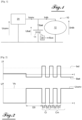
- FIG. 1 represents an electrical network 10 comprising a battery 11 and at least one consumer 12.
- a DC/DC power converter 20 couples the network 10 to a second network not shown.
- the network 10 and/or said second network are coupled to a vehicle traction chain.
- the electrical network 10 belongs to a motor vehicle.
- the motor vehicle has an electric motor or a thermal/electric hybrid motor.
- the power converter 20 is configured to recharge the battery 11 and/or supply the consumer 12 with electrical energy.
- the electrical network 10 is adapted to the circulation of a current having a voltage of approximately 12 Volts.
- the second network is adapted to the circulation of a current having a voltage higher than the voltage of the network 10 to which said battery 11 belongs.
- the power converter 20 is able to be activated in order to deliver an electric current having a non-zero output voltage Uconv, for example equal to 12.8 Volts.
- the power converter 20 When the power converter 20 is active, the current delivered by it makes it possible to recharge the battery 11 and to power the consumer 12 of the electrical network 10. Such a recharge is shown on the figure 2 by a negative intensity Ibat of the current circulating in the battery 11.
- the power converter 20 is able to be inactivated so as not to deliver any electric current.
- the inactivation of the power converter 20 is not complete so that the converter 20 delivers an electric current having an output voltage Uconv lower than the voltage Urdb required to supply the consumer 12 of the electrical network 10, for example equal to 10.5 Volts (adjustable value between 9.5 Volts and 10.5 Volts).
- the battery 11 discharges to maintain a voltage Urdb in the electrical network 10 sufficient to supply the consumer 12 in the situation where the battery 11 is capable of doing so.
- the minimum voltage Urdb in the electrical network 10 is guaranteed by the power converter 20. In this last situation, battery 11 is declared faulty.
- the battery 11 discharges to deliver an electric current making it possible to power the consumer 12 of the electrical network 10. Such a discharge is shown on the figure 2 by an intensity Ibat of the current circulating in the positive battery 11.
- the at least one consumer 12 is a device belonging to the electrical steering assistance of the motor vehicle, to the braking means of the motor vehicle, to the means of starting the thermal engine of the motor vehicle and/or to the means lighting or signaling of the motor vehicle.
- a method for diagnosing the state of the battery 11 comprises an original power supply phase of the on-board network 10 by the power converter 20.
- This original power phase recharges the battery 11 and supplies the consumer 12.
- this original power supply is initiated by opening a door of the motor vehicle. According to different embodiments, this original power supply is initiated by contacting the vehicle.
- the original power supply is carried out for a duration D0.
- the original power supply is produced at a voltage Vs.
- the voltage Vs is for example equal to 12.8 Volts for example adjustable as a function of the rest voltage of the battery 11 depending on the technology of the battery 11.
- the state of charge of the battery 11 is measured before implementing the diagnostic method.
- the method comprises a comparison of the value of an intensity Iconv of the current delivered by the converter 20 with a predetermined original diagnostic threshold Isd.
- the original diagnostic threshold Isd is greater than or equal to the need of the consumer 12 so that the battery 11 does not discharge.
- the method comprises a comparison of the difference of the value of the intensity Iconv of the current delivered by the converter 20 by the value of the intensity Ibat of the current delivered by the battery 11 with a predetermined original diagnostic threshold Isd, for example equal to 70 Amps.
- the method comprises, according to the embodiment shown, an initialization cycle Ci comprising an inactivation of the power converter 20 for a duration D1, as shown in the figure 2 .
- the duration D1 is approximately equal to 200 milliseconds.
- the inactivation of the power converter 20 forces the battery 11 to discharge in order to supply the consumer 12. Said inactivation of the power converter 20 of the initialization cycle Ci is not necessarily complete, so that the converter 20 delivers a current electric low enough for the battery 11 to discharge, can thus be called initialization discharge of the battery (11).
- the initialization cycle Ci includes activation of the power converter 20 for a duration D2, as shown in the figure. figure 2 .
- the duration D2 is approximately equal to 200 milliseconds.
- the activation of the converter 20 supplies the consumer with electrical energy at a maximum voltage which is for example the polarization voltage of the battery 11 of 12.8 Volts with the aim of not polarizing it before initiating the next cycle.
- This initialization cycle Ci makes it possible to cancel the polarization effect of the battery 11.
- the method then comprises at least one evaluation cycle Cm, each evaluation cycle Cm comprising an inactivation during the duration D1 and an activation during the duration D2 of the converter 20.
- the inactivation and activation durations are different from each other and/or between the initialization cycle Ci and the evaluation cycle Cm.
- the method comprises, when the power converter 20 is inactivated, a measurement of a voltage Ubat across the terminals of the battery 11 and of the intensity Ibat of the current circulating in the battery 11.
- the method includes a calculation of an internal discharge resistance Rint of the battery 11 by dividing the voltage Ubat across the terminals of the battery 11 by the intensity Ibat of the current circulating in the battery 11 measured.
- the internal discharge resistor Rint represents the capacity of the battery 11 to provide power.
- measurements of the voltage Ubat across the terminals of the battery 11 and of the intensity Ibat of the current circulating in the battery 11 are carried out every millisecond (i.e. at a frequency of 1 kilohertz). For each cycle Cm of evaluation of the converter 20 an average of all the voltages Ubat and intensities Ibat measured or an average of all the internal resistances Rint calculated is made.
- the measurement(s) of the voltage Ubat across the terminals of the battery 11 and the intensity Ibat of the current circulating in the battery 11 and the calculation(s) of the internal discharge resistance Rint are carried out from 'an intensity gradient of the current circulating in the battery 11 over a given duration greater than a predetermined threshold.
- This threshold is for example equal to 70 Amps for a duration of for example 5 milliseconds.
- This internal Rint resistance or this average internal Rint resistance calculated at each evaluation cycle Cm is then compared, for example in a chart, to at least one predetermined health status diagnostic threshold of the battery 11.
- the battery 11 is considered to be in good condition, to be regenerated or to recycle meaning for example that the capacity of the battery 11 to provide power is considered nominal, temporarily degraded, degraded or even incapable.
- the comparison leading to the most unfavorable result is taken into account.
- an average of the results of the comparisons is carried out.
- the regeneration of the battery 11 makes it possible, in the best case, to restore to it functional characteristics substantially identical to the nominal characteristics of a new battery.
- the method then comprises processing the result of the comparison by the electrical energy management system.
- information is generated allowing functions of the vehicle to be reconfigured in particular by limiting the maximum current level of certain functions such as for example the steering assist function.
- the method includes an indication of the result, for example, to the driver of the motor vehicle so that he can adapt the use of his vehicle according to the level of seriousness of the information brought to his attention.
- this information is recorded and dated in order to be able, for example, to be analyzed by the after-sales service of the vehicle manufacturer and/or to serve as objective proof during a legal appeal if an accident occurs at the same time. upon the appearance of the information brought to the driver's attention, in order to clarify the various responsibilities associated with this accident.
- an intensity Irdb of a current circulating in the consumer 12 is equal to the sum of the intensity Iconv of the current delivered by the power converter 20 and the intensity Ibat of the current circulating in the battery 11.
- the measurements of the voltage Ubat at the terminals of the battery 11 and of the intensity Ibat of the current circulating in the battery 11 are carried out by a Battery State of Charge Box (BECB) 30 present on all vehicles.
- BECB Battery State of Charge Box
- the impedance across the consumer 12 is less than a critical impedance.
- Such a method for diagnosing the battery 11 of a motor vehicle thus allows, without requiring the delivery of significant power by said battery 11 in order to be able to drive, the verification of the capacity of the battery 11 to provide sufficient power to do so. operate correctly the consumer 12.
- Such a diagnostic method also allows the manufacture of a lighter, less expensive and less bulky vehicle than those of the prior art.
Landscapes
- Physics & Mathematics (AREA)
- General Physics & Mathematics (AREA)
- Electric Propulsion And Braking For Vehicles (AREA)
- Secondary Cells (AREA)
- Tests Of Electric Status Of Batteries (AREA)
- Charge And Discharge Circuits For Batteries Or The Like (AREA)
Claims (10)
- Verfahren zur Zustandsdiagnose einer Batterie (11) eines elektrischen Netzes (10) eines Kraftfahrzeugs, wobei das Netz (10) einen Verbraucher (12) umfasst, der von der Batterie (11) und einem Stromrichter mit elektrischem Gleichstrom versorgt wird (20), gekoppelt an eine Traktionskette des Fahrzeugs und an das Netzwerk (10), wobei das Verfahren eine Messung mindestens eines Parameters ( Ubat , Ibat ) des Betriebs der Batterie (11) während einer Entladung der Batterie (11) umfasst) und einen Vergleich des gemessenen Betriebsparameters ( Ubat , Ibat ) mit einem vorbestimmten Zustandsdiagnoseschwellenwert, wobei das Verfahren dadurch gekennzeichnet ist, dass es vor der Messung eine Initialisierungsentladung der Batterie (11) und dann eine Initialisierungsaktivierung des Wandlers umfasst (20) bei einer Ausgangsspannung ( Uconv ), die größer oder gleich einer Spannung ( Urdb ) ist, die zum Betreiben des Verbrauchers (12) erforderlich ist, wodurch die Initialisierungsentladung der Batterie (11) beendet wird.
- Diagnoseverfahren nach dem vorhergehenden Anspruch, dadurch gekennzeichnet, dass der mindestens eine gemessene Betriebsparameter ( Ubat , Ibat ) der Batterie (11) ein Drehmoment ist, das eine Spannung ( Ubat ) an den Anschlüssen der Batterie (11) und eine Intensität umfasst ( Ibat ) eines in dem die Batterie (11) umfassenden Zweig des Netzes (10) zirkulierenden Stroms und dadurch, dass der Vergleich des Betriebsparameters ( Ubat , Ibat ) durch Berechnung eines Innenwiderstands ( Rint ) der Entladung erfolgt Batterie (11) durch Teilen der Spannung ( Ubat ) durch die Intensität ( Ibat ).
- Diagnoseverfahren nach einem der vorhergehenden Ansprüche, dadurch gekennzeichnet, dass die Initialisierungsentladung und die Initialisierungsaktivierung nach einer Zugangsanfrage zum Kraftfahrzeug oder einer Aktivierungsanfrage des Kraftfahrzeugs durchgeführt werden.
- Diagnoseverfahren nach einem der vorhergehenden Ansprüche, dadurch gekennzeichnet, dass es nach der Initialisierungsaktivierung des Wandlers (20) mehrere aufeinanderfolgende Messungen des mindestens einen Parameters (Ubat, Ibat ) des Betriebs der Batterie (11) umfasst Entladungen der Batterie (11) und zwischen jeder Entladung Aktivierung des Wandlers (20) bei einer Ausgangsspannung ( Uconv ), die größer oder gleich der zur Versorgung des Verbrauchers (12) erforderlichen Spannung ( Urdb ) ist, wie z Nach jeder Entladung wird ein Vergleich durchgeführt, wobei der ungünstigste Vergleich zur Diagnose des Batteriezustands berücksichtigt wird (11).
- Diagnoseverfahren nach dem vorhergehenden Anspruch, dadurch gekennzeichnet, dass die Entladung(en) der Batterie (11) und/oder die Aktivierung(en) des Wandlers (20) zwischen 50 Millisekunden und 250 Millisekunden dauern.
- Diagnoseverfahren nach einem der vorhergehenden Ansprüche, dadurch gekennzeichnet, dass es vor der Initialisierungsentladung und der Initialisierungsaktivierung eine ursprüngliche Gleichstromversorgung des Netzes (10) durch den Leistungswandler (20) und dann einen Vergleich einer Intensität umfasst ( Iconv ) des vom Wandler (20) gelieferten Stroms mit einer vorgegebenen ursprünglichen Diagnoseschwelle ( Isd ), wobei die ursprüngliche Diagnoseschwelle ( Isd ) größer oder gleich der zur Versorgung des Verbrauchers (12) erforderlichen Spannung ( Urdb ) ist, wobei der Intensitätsvergleich den Abschluss der folgenden Schritte bedingt.
- Diagnoseverfahren nach einem der vorhergehenden Ansprüche, dadurch gekennzeichnet, dass es abhängig vom Ergebnis des Vergleichs des gemessenen Betriebsparameters ( Ubat , Ibat ) der Batterie (11) mit der Diagnosezustandsschwelle eine Klassifizierung umfasst Danach gilt die Batterie (11) als in gutem Zustand und muss regeneriert oder recycelt werden.
- Diagnoseverfahren nach einem der vorhergehenden Ansprüche, dadurch gekennzeichnet, dass es eine Validierung des Ergebnisses des Vergleichs umfasst, indem überprüft wird, ob eine Intensität ( Irdb ) eines im Verbraucher (12) zirkulierenden Stroms gleich der Summe einer Intensität ist ( Iconv ) des vom Leistungswandler (20) gelieferten Stroms und die Intensität ( Ibat ) des in der Batterie (11) zirkulierenden Stroms.
- Diagnoseverfahren nach einem der vorhergehenden Ansprüche, dadurch gekennzeichnet, dass es nach dem Vergleich des gemessenen Betriebsparameters ( Ubat , Ibat ) der Batterie mit dem Zustandsdiagnoseschwellenwert eine Anzeige des Ergebnisses des Vergleichs an den Fahrer des Fahrzeugs umfasst Kraftfahrzeug.
- Kraftfahrzeug mit Elektromotor oder thermischem/elektrischem Hybridmotor, wobei das Fahrzeug ein erstes elektrisches Netzwerk (10), ein zweites elektrisches Netzwerk und einen DC/DC-Leistungswandler (20) umfasst, der das erste Netzwerk (10) und das zweite Netzwerk koppelt erstes Netzwerk (10), umfassend eine Batterie (11) und mindestens einen Verbraucher (12), der von der Batterie (11) und/oder vom Stromrichter (20) mit elektrischem Gleichstrom versorgt wird, wobei das Kraftfahrzeug dadurch gekennzeichnet ist, dass es Folgendes umfasst: ein System, das ein Batteriediagnoseverfahren (11) nach einem der vorhergehenden Ansprüche implementiert.
Applications Claiming Priority (2)
| Application Number | Priority Date | Filing Date | Title |
|---|---|---|---|
| FR1901726A FR3093187B1 (fr) | 2019-02-21 | 2019-02-21 | Procédé de diagnostic d’une batterie d’un véhicule automobile |
| PCT/FR2019/053248 WO2020169891A1 (fr) | 2019-02-21 | 2019-12-20 | Procédé de diagnostic d'une batterie d'un véhicule automobile |
Publications (2)
| Publication Number | Publication Date |
|---|---|
| EP3928107A1 EP3928107A1 (de) | 2021-12-29 |
| EP3928107B1 true EP3928107B1 (de) | 2024-03-20 |
Family
ID=67185326
Family Applications (1)
| Application Number | Title | Priority Date | Filing Date |
|---|---|---|---|
| EP19848809.0A Active EP3928107B1 (de) | 2019-02-21 | 2019-12-20 | Verfahren zur diagnose einer batterie eines kraftfahrzeugs |
Country Status (5)
| Country | Link |
|---|---|
| EP (1) | EP3928107B1 (de) |
| CN (1) | CN113454476B (de) |
| ES (1) | ES2977207T3 (de) |
| FR (1) | FR3093187B1 (de) |
| WO (1) | WO2020169891A1 (de) |
Family Cites Families (15)
| Publication number | Priority date | Publication date | Assignee | Title |
|---|---|---|---|---|
| JPH0650340B2 (ja) * | 1986-04-14 | 1994-06-29 | 株式会社日立製作所 | 自動車用バツテリの寿命診断装置 |
| CN1655419A (zh) * | 2004-02-13 | 2005-08-17 | 合肥同智科技发展有限公司 | 蓄电池快/慢充电控制方法 |
| KR100944793B1 (ko) * | 2007-09-05 | 2010-03-02 | 한국전기연구원 | 태양전지 어레이의 열화 진단기능 부가형 태양광 발전용전력변환장치 및 그 운용방법 |
| US9782592B2 (en) * | 2010-07-15 | 2017-10-10 | Boston Scientific Neuromodulation Corporation | Energy efficient high frequency nerve blocking technique |
| WO2012046285A1 (ja) * | 2010-10-04 | 2012-04-12 | 古河電気工業株式会社 | バッテリの状態推定方法及び電源システム |
| FR2984622B1 (fr) * | 2011-12-19 | 2014-05-16 | Schneider Electric Ind Sas | Procede de controle et d'optimisation de fonctionnement d'une borne de chargement d'un vehicule electrique et borne de chargement pour la mise en oeuvre dudit procede |
| FR3009869B1 (fr) * | 2013-08-22 | 2016-10-21 | Renault Sa | Procede de detection d'une deconnexion de batterie d'alimentation d'un vehicule automobile |
| CN104626995B (zh) * | 2013-11-06 | 2016-09-28 | 联合汽车电子有限公司 | 电动汽车高压放电系统 |
| CN103904746A (zh) * | 2014-04-04 | 2014-07-02 | 西北工业大学 | 一种智能型正负脉冲动力电池快速充电机及充电方法 |
| CN104269583B (zh) * | 2014-09-25 | 2016-07-06 | 重庆邮电大学 | 一种带负脉冲的分段恒流恒压交替充电方法 |
| WO2016194271A1 (ja) * | 2015-06-05 | 2016-12-08 | パナソニックIpマネジメント株式会社 | 補機用バッテリの状態判定装置、及び、補機用バッテリの状態判定方法 |
| CN105891717A (zh) * | 2015-07-01 | 2016-08-24 | 乐视移动智能信息技术(北京)有限公司 | 获取电池电量的方法和装置 |
| US10790688B2 (en) * | 2015-09-23 | 2020-09-29 | Faraday & Future Inc. | Method for measuring battery parameters under discharge or charge |
| CN105259508A (zh) * | 2015-10-14 | 2016-01-20 | 惠州Tcl移动通信有限公司 | 一种终端及计算其初始电量的方法 |
| FR3044099B1 (fr) | 2015-11-20 | 2018-11-16 | Psa Automobiles Sa. | Dispositif de diagnostic de batterie |
-
2019
- 2019-02-21 FR FR1901726A patent/FR3093187B1/fr not_active Expired - Fee Related
- 2019-12-20 ES ES19848809T patent/ES2977207T3/es active Active
- 2019-12-20 CN CN201980092268.3A patent/CN113454476B/zh active Active
- 2019-12-20 WO PCT/FR2019/053248 patent/WO2020169891A1/fr not_active Ceased
- 2019-12-20 EP EP19848809.0A patent/EP3928107B1/de active Active
Also Published As
| Publication number | Publication date |
|---|---|
| ES2977207T3 (es) | 2024-08-20 |
| FR3093187B1 (fr) | 2021-02-19 |
| EP3928107A1 (de) | 2021-12-29 |
| FR3093187A1 (fr) | 2020-08-28 |
| CN113454476A (zh) | 2021-09-28 |
| WO2020169891A1 (fr) | 2020-08-27 |
| CN113454476B (zh) | 2025-04-08 |
Similar Documents
| Publication | Publication Date | Title |
|---|---|---|
| FR2988856A1 (fr) | Procede et dispositif de diagnostic d'un circuit de decharge d'un systeme electrique | |
| EP2794342B1 (de) | Verfahren zur überwachung und optimierung der betriebsweise eines gebührenterminals für ein elektrofahrzeug und gebührenterminal zur durchführung des verfahrens | |
| FR3009869A1 (fr) | Procede de detection d'une deconnexion de batterie d'alimentation d'un vehicule automobile | |
| FR2918027A1 (fr) | Procede de pilotage de systeme micro-hybride pour vehicule, ainsi qu'unite de stockage d'energie et systeme hybride pour la mise en oeuvre de celui-ci | |
| EP2396838A1 (de) | Verfahren und einrichtung zum klassifizieren einer batterie | |
| EP4088126B1 (de) | Diagnose des zustands einer zusatzbatterie eines fahrzeugs durch stromimpulse | |
| FR2987939A1 (fr) | Procede de gestion d'un systeme de vehicule automobile et systeme adapte a la mise en oeuvre du procede | |
| FR2994772A1 (fr) | Procede de charge d'une batterie | |
| EP3928107B1 (de) | Verfahren zur diagnose einer batterie eines kraftfahrzeugs | |
| EP3092144B1 (de) | Verfahren zur schätzung der eignung einer batterie zur speisung eines vorbestimmten leistungsprofils | |
| FR2949864A1 (fr) | Procede de determination d'un etat de fonctionnement de moyens de stockage d'energie electrique constitues d'au moins un supercondensateur | |
| WO2012085459A1 (fr) | Dispositif et procede de conversion dc/dc dans le reseau de bord d'un vehicule | |
| WO2017085429A1 (fr) | Dispositif de diagnostic de batterie | |
| WO2023187270A1 (fr) | Procede de controle d'un vehicule comprenant un dispositif de test d'isolement d'un circuit electrique | |
| FR3009754A1 (fr) | Diagnostic de la resistance interne d'une batterie electrique | |
| FR3148176A1 (fr) | Procede d’equilibrage d’un systeme de stockage d’energie | |
| EP4251465B1 (de) | Verfahren mit einem batteriezustandszähler | |
| FR2751145A1 (fr) | Dispositif de controle de la charge d'un supercondensateur et procede de commande d'un tel dispositif | |
| EP4252017B1 (de) | Verfahren mit einer batteriezustandskarte | |
| FR3104264A1 (fr) | Diagnostic d’une batterie basse-tension dans un vehicule electrique | |
| WO2006024802A1 (fr) | Procede d'évaluation de l'etat d'une batterie electrochimique et dispositif de mise en œuvre | |
| FR3105433A1 (fr) | Procédé de diagnostic pour une batterie de véhicule | |
| WO2016009130A1 (fr) | Circuit électrique et procédé de gestion associé | |
| FR3104726A1 (fr) | Procede de controle de l’etat de sante d’un stockeur de vehicules automobiles | |
| FR3116499A1 (fr) | Procede de securisation d’une batterie. |
Legal Events
| Date | Code | Title | Description |
|---|---|---|---|
| STAA | Information on the status of an ep patent application or granted ep patent |
Free format text: STATUS: UNKNOWN |
|
| STAA | Information on the status of an ep patent application or granted ep patent |
Free format text: STATUS: THE INTERNATIONAL PUBLICATION HAS BEEN MADE |
|
| PUAI | Public reference made under article 153(3) epc to a published international application that has entered the european phase |
Free format text: ORIGINAL CODE: 0009012 |
|
| STAA | Information on the status of an ep patent application or granted ep patent |
Free format text: STATUS: REQUEST FOR EXAMINATION WAS MADE |
|
| 17P | Request for examination filed |
Effective date: 20210706 |
|
| AK | Designated contracting states |
Kind code of ref document: A1 Designated state(s): AL AT BE BG CH CY CZ DE DK EE ES FI FR GB GR HR HU IE IS IT LI LT LU LV MC MK MT NL NO PL PT RO RS SE SI SK SM TR |
|
| DAV | Request for validation of the european patent (deleted) | ||
| DAX | Request for extension of the european patent (deleted) | ||
| GRAP | Despatch of communication of intention to grant a patent |
Free format text: ORIGINAL CODE: EPIDOSNIGR1 |
|
| STAA | Information on the status of an ep patent application or granted ep patent |
Free format text: STATUS: GRANT OF PATENT IS INTENDED |
|
| INTG | Intention to grant announced |
Effective date: 20231106 |
|
| RIN1 | Information on inventor provided before grant (corrected) |
Inventor name: MONDOLONI, CHRISTIAN Inventor name: BOUCLY, BERNARD Inventor name: PERSEVAL, HERVE |
|
| RAP3 | Party data changed (applicant data changed or rights of an application transferred) |
Owner name: STELLANTIS AUTO SAS |
|
| GRAS | Grant fee paid |
Free format text: ORIGINAL CODE: EPIDOSNIGR3 |
|
| GRAA | (expected) grant |
Free format text: ORIGINAL CODE: 0009210 |
|
| STAA | Information on the status of an ep patent application or granted ep patent |
Free format text: STATUS: THE PATENT HAS BEEN GRANTED |
|
| REG | Reference to a national code |
Ref country code: DE Ref legal event code: R084 Ref document number: 602019048750 Country of ref document: DE |
|
| AK | Designated contracting states |
Kind code of ref document: B1 Designated state(s): AL AT BE BG CH CY CZ DE DK EE ES FI FR GB GR HR HU IE IS IT LI LT LU LV MC MK MT NL NO PL PT RO RS SE SI SK SM TR |
|
| REG | Reference to a national code |
Ref country code: GB Ref legal event code: FG4D Free format text: NOT ENGLISH |
|
| REG | Reference to a national code |
Ref country code: CH Ref legal event code: EP |
|
| REG | Reference to a national code |
Ref country code: DE Ref legal event code: R096 Ref document number: 602019048750 Country of ref document: DE |
|
| REG | Reference to a national code |
Ref country code: IE Ref legal event code: FG4D Free format text: LANGUAGE OF EP DOCUMENT: FRENCH |
|
| REG | Reference to a national code |
Ref country code: GB Ref legal event code: 746 Effective date: 20240410 |
|
| REG | Reference to a national code |
Ref country code: ES Ref legal event code: GC2A Effective date: 20240508 |
|
| PG25 | Lapsed in a contracting state [announced via postgrant information from national office to epo] |
Ref country code: LT Free format text: LAPSE BECAUSE OF FAILURE TO SUBMIT A TRANSLATION OF THE DESCRIPTION OR TO PAY THE FEE WITHIN THE PRESCRIBED TIME-LIMIT Effective date: 20240320 |
|
| REG | Reference to a national code |
Ref country code: LT Ref legal event code: MG9D |
|
| PG25 | Lapsed in a contracting state [announced via postgrant information from national office to epo] |
Ref country code: GR Free format text: LAPSE BECAUSE OF FAILURE TO SUBMIT A TRANSLATION OF THE DESCRIPTION OR TO PAY THE FEE WITHIN THE PRESCRIBED TIME-LIMIT Effective date: 20240621 |
|
| PG25 | Lapsed in a contracting state [announced via postgrant information from national office to epo] |
Ref country code: HR Free format text: LAPSE BECAUSE OF FAILURE TO SUBMIT A TRANSLATION OF THE DESCRIPTION OR TO PAY THE FEE WITHIN THE PRESCRIBED TIME-LIMIT Effective date: 20240320 Ref country code: RS Free format text: LAPSE BECAUSE OF FAILURE TO SUBMIT A TRANSLATION OF THE DESCRIPTION OR TO PAY THE FEE WITHIN THE PRESCRIBED TIME-LIMIT Effective date: 20240620 |
|
| REG | Reference to a national code |
Ref country code: NL Ref legal event code: MP Effective date: 20240320 |
|
| PG25 | Lapsed in a contracting state [announced via postgrant information from national office to epo] |
Ref country code: RS Free format text: LAPSE BECAUSE OF FAILURE TO SUBMIT A TRANSLATION OF THE DESCRIPTION OR TO PAY THE FEE WITHIN THE PRESCRIBED TIME-LIMIT Effective date: 20240620 Ref country code: NO Free format text: LAPSE BECAUSE OF FAILURE TO SUBMIT A TRANSLATION OF THE DESCRIPTION OR TO PAY THE FEE WITHIN THE PRESCRIBED TIME-LIMIT Effective date: 20240620 Ref country code: LT Free format text: LAPSE BECAUSE OF FAILURE TO SUBMIT A TRANSLATION OF THE DESCRIPTION OR TO PAY THE FEE WITHIN THE PRESCRIBED TIME-LIMIT Effective date: 20240320 Ref country code: HR Free format text: LAPSE BECAUSE OF FAILURE TO SUBMIT A TRANSLATION OF THE DESCRIPTION OR TO PAY THE FEE WITHIN THE PRESCRIBED TIME-LIMIT Effective date: 20240320 Ref country code: GR Free format text: LAPSE BECAUSE OF FAILURE TO SUBMIT A TRANSLATION OF THE DESCRIPTION OR TO PAY THE FEE WITHIN THE PRESCRIBED TIME-LIMIT Effective date: 20240621 Ref country code: FI Free format text: LAPSE BECAUSE OF FAILURE TO SUBMIT A TRANSLATION OF THE DESCRIPTION OR TO PAY THE FEE WITHIN THE PRESCRIBED TIME-LIMIT Effective date: 20240320 Ref country code: BG Free format text: LAPSE BECAUSE OF FAILURE TO SUBMIT A TRANSLATION OF THE DESCRIPTION OR TO PAY THE FEE WITHIN THE PRESCRIBED TIME-LIMIT Effective date: 20240320 |
|
| REG | Reference to a national code |
Ref country code: AT Ref legal event code: MK05 Ref document number: 1668284 Country of ref document: AT Kind code of ref document: T Effective date: 20240320 |
|
| REG | Reference to a national code |
Ref country code: ES Ref legal event code: FG2A Ref document number: 2977207 Country of ref document: ES Kind code of ref document: T3 Effective date: 20240820 |
|
| PG25 | Lapsed in a contracting state [announced via postgrant information from national office to epo] |
Ref country code: SE Free format text: LAPSE BECAUSE OF FAILURE TO SUBMIT A TRANSLATION OF THE DESCRIPTION OR TO PAY THE FEE WITHIN THE PRESCRIBED TIME-LIMIT Effective date: 20240320 Ref country code: LV Free format text: LAPSE BECAUSE OF FAILURE TO SUBMIT A TRANSLATION OF THE DESCRIPTION OR TO PAY THE FEE WITHIN THE PRESCRIBED TIME-LIMIT Effective date: 20240320 |
|
| PG25 | Lapsed in a contracting state [announced via postgrant information from national office to epo] |
Ref country code: NL Free format text: LAPSE BECAUSE OF FAILURE TO SUBMIT A TRANSLATION OF THE DESCRIPTION OR TO PAY THE FEE WITHIN THE PRESCRIBED TIME-LIMIT Effective date: 20240320 |
|
| PG25 | Lapsed in a contracting state [announced via postgrant information from national office to epo] |
Ref country code: NL Free format text: LAPSE BECAUSE OF FAILURE TO SUBMIT A TRANSLATION OF THE DESCRIPTION OR TO PAY THE FEE WITHIN THE PRESCRIBED TIME-LIMIT Effective date: 20240320 |
|
| PG25 | Lapsed in a contracting state [announced via postgrant information from national office to epo] |
Ref country code: IS Free format text: LAPSE BECAUSE OF FAILURE TO SUBMIT A TRANSLATION OF THE DESCRIPTION OR TO PAY THE FEE WITHIN THE PRESCRIBED TIME-LIMIT Effective date: 20240720 |
|
| PG25 | Lapsed in a contracting state [announced via postgrant information from national office to epo] |
Ref country code: PT Free format text: LAPSE BECAUSE OF FAILURE TO SUBMIT A TRANSLATION OF THE DESCRIPTION OR TO PAY THE FEE WITHIN THE PRESCRIBED TIME-LIMIT Effective date: 20240722 Ref country code: SM Free format text: LAPSE BECAUSE OF FAILURE TO SUBMIT A TRANSLATION OF THE DESCRIPTION OR TO PAY THE FEE WITHIN THE PRESCRIBED TIME-LIMIT Effective date: 20240320 |
|
| PG25 | Lapsed in a contracting state [announced via postgrant information from national office to epo] |
Ref country code: EE Free format text: LAPSE BECAUSE OF FAILURE TO SUBMIT A TRANSLATION OF THE DESCRIPTION OR TO PAY THE FEE WITHIN THE PRESCRIBED TIME-LIMIT Effective date: 20240320 Ref country code: CZ Free format text: LAPSE BECAUSE OF FAILURE TO SUBMIT A TRANSLATION OF THE DESCRIPTION OR TO PAY THE FEE WITHIN THE PRESCRIBED TIME-LIMIT Effective date: 20240320 |
|
| PG25 | Lapsed in a contracting state [announced via postgrant information from national office to epo] |
Ref country code: AT Free format text: LAPSE BECAUSE OF FAILURE TO SUBMIT A TRANSLATION OF THE DESCRIPTION OR TO PAY THE FEE WITHIN THE PRESCRIBED TIME-LIMIT Effective date: 20240320 |
|
| PG25 | Lapsed in a contracting state [announced via postgrant information from national office to epo] |
Ref country code: PL Free format text: LAPSE BECAUSE OF FAILURE TO SUBMIT A TRANSLATION OF THE DESCRIPTION OR TO PAY THE FEE WITHIN THE PRESCRIBED TIME-LIMIT Effective date: 20240320 |
|
| PG25 | Lapsed in a contracting state [announced via postgrant information from national office to epo] |
Ref country code: SK Free format text: LAPSE BECAUSE OF FAILURE TO SUBMIT A TRANSLATION OF THE DESCRIPTION OR TO PAY THE FEE WITHIN THE PRESCRIBED TIME-LIMIT Effective date: 20240320 |
|
| PG25 | Lapsed in a contracting state [announced via postgrant information from national office to epo] |
Ref country code: SM Free format text: LAPSE BECAUSE OF FAILURE TO SUBMIT A TRANSLATION OF THE DESCRIPTION OR TO PAY THE FEE WITHIN THE PRESCRIBED TIME-LIMIT Effective date: 20240320 Ref country code: SK Free format text: LAPSE BECAUSE OF FAILURE TO SUBMIT A TRANSLATION OF THE DESCRIPTION OR TO PAY THE FEE WITHIN THE PRESCRIBED TIME-LIMIT Effective date: 20240320 Ref country code: RO Free format text: LAPSE BECAUSE OF FAILURE TO SUBMIT A TRANSLATION OF THE DESCRIPTION OR TO PAY THE FEE WITHIN THE PRESCRIBED TIME-LIMIT Effective date: 20240320 Ref country code: PT Free format text: LAPSE BECAUSE OF FAILURE TO SUBMIT A TRANSLATION OF THE DESCRIPTION OR TO PAY THE FEE WITHIN THE PRESCRIBED TIME-LIMIT Effective date: 20240722 Ref country code: PL Free format text: LAPSE BECAUSE OF FAILURE TO SUBMIT A TRANSLATION OF THE DESCRIPTION OR TO PAY THE FEE WITHIN THE PRESCRIBED TIME-LIMIT Effective date: 20240320 Ref country code: IS Free format text: LAPSE BECAUSE OF FAILURE TO SUBMIT A TRANSLATION OF THE DESCRIPTION OR TO PAY THE FEE WITHIN THE PRESCRIBED TIME-LIMIT Effective date: 20240720 Ref country code: EE Free format text: LAPSE BECAUSE OF FAILURE TO SUBMIT A TRANSLATION OF THE DESCRIPTION OR TO PAY THE FEE WITHIN THE PRESCRIBED TIME-LIMIT Effective date: 20240320 Ref country code: CZ Free format text: LAPSE BECAUSE OF FAILURE TO SUBMIT A TRANSLATION OF THE DESCRIPTION OR TO PAY THE FEE WITHIN THE PRESCRIBED TIME-LIMIT Effective date: 20240320 Ref country code: AT Free format text: LAPSE BECAUSE OF FAILURE TO SUBMIT A TRANSLATION OF THE DESCRIPTION OR TO PAY THE FEE WITHIN THE PRESCRIBED TIME-LIMIT Effective date: 20240320 |
|
| PG25 | Lapsed in a contracting state [announced via postgrant information from national office to epo] |
Ref country code: IT Free format text: LAPSE BECAUSE OF FAILURE TO SUBMIT A TRANSLATION OF THE DESCRIPTION OR TO PAY THE FEE WITHIN THE PRESCRIBED TIME-LIMIT Effective date: 20240320 |
|
| REG | Reference to a national code |
Ref country code: DE Ref legal event code: R097 Ref document number: 602019048750 Country of ref document: DE |
|
| PG25 | Lapsed in a contracting state [announced via postgrant information from national office to epo] |
Ref country code: IT Free format text: LAPSE BECAUSE OF FAILURE TO SUBMIT A TRANSLATION OF THE DESCRIPTION OR TO PAY THE FEE WITHIN THE PRESCRIBED TIME-LIMIT Effective date: 20240320 |
|
| PG25 | Lapsed in a contracting state [announced via postgrant information from national office to epo] |
Ref country code: DK Free format text: LAPSE BECAUSE OF FAILURE TO SUBMIT A TRANSLATION OF THE DESCRIPTION OR TO PAY THE FEE WITHIN THE PRESCRIBED TIME-LIMIT Effective date: 20240320 |
|
| PLBE | No opposition filed within time limit |
Free format text: ORIGINAL CODE: 0009261 |
|
| STAA | Information on the status of an ep patent application or granted ep patent |
Free format text: STATUS: NO OPPOSITION FILED WITHIN TIME LIMIT |
|
| PG25 | Lapsed in a contracting state [announced via postgrant information from national office to epo] |
Ref country code: DK Free format text: LAPSE BECAUSE OF FAILURE TO SUBMIT A TRANSLATION OF THE DESCRIPTION OR TO PAY THE FEE WITHIN THE PRESCRIBED TIME-LIMIT Effective date: 20240320 |
|
| 26N | No opposition filed |
Effective date: 20241223 |
|
| PG25 | Lapsed in a contracting state [announced via postgrant information from national office to epo] |
Ref country code: SI Free format text: LAPSE BECAUSE OF FAILURE TO SUBMIT A TRANSLATION OF THE DESCRIPTION OR TO PAY THE FEE WITHIN THE PRESCRIBED TIME-LIMIT Effective date: 20240320 |
|
| PG25 | Lapsed in a contracting state [announced via postgrant information from national office to epo] |
Ref country code: MC Free format text: LAPSE BECAUSE OF FAILURE TO SUBMIT A TRANSLATION OF THE DESCRIPTION OR TO PAY THE FEE WITHIN THE PRESCRIBED TIME-LIMIT Effective date: 20240320 |
|
| REG | Reference to a national code |
Ref country code: CH Ref legal event code: PL |
|
| PG25 | Lapsed in a contracting state [announced via postgrant information from national office to epo] |
Ref country code: LU Free format text: LAPSE BECAUSE OF NON-PAYMENT OF DUE FEES Effective date: 20241220 |
|
| REG | Reference to a national code |
Ref country code: BE Ref legal event code: MM Effective date: 20241231 |
|
| PG25 | Lapsed in a contracting state [announced via postgrant information from national office to epo] |
Ref country code: BE Free format text: LAPSE BECAUSE OF NON-PAYMENT OF DUE FEES Effective date: 20241231 |
|
| PG25 | Lapsed in a contracting state [announced via postgrant information from national office to epo] |
Ref country code: CH Free format text: LAPSE BECAUSE OF NON-PAYMENT OF DUE FEES Effective date: 20241231 |
|
| PG25 | Lapsed in a contracting state [announced via postgrant information from national office to epo] |
Ref country code: IE Free format text: LAPSE BECAUSE OF NON-PAYMENT OF DUE FEES Effective date: 20241220 |
|
| PGFP | Annual fee paid to national office [announced via postgrant information from national office to epo] |
Ref country code: DE Payment date: 20251126 Year of fee payment: 7 |
|
| PGFP | Annual fee paid to national office [announced via postgrant information from national office to epo] |
Ref country code: GB Payment date: 20251119 Year of fee payment: 7 |
|
| PGFP | Annual fee paid to national office [announced via postgrant information from national office to epo] |
Ref country code: FR Payment date: 20251120 Year of fee payment: 7 |
|
| PGFP | Annual fee paid to national office [announced via postgrant information from national office to epo] |
Ref country code: ES Payment date: 20260102 Year of fee payment: 7 |