EP4096860B1 - Ensemble de traitement de matériau à l'aide d'un faisceau laser, notamment destiné au perçage par laser - Google Patents
Ensemble de traitement de matériau à l'aide d'un faisceau laser, notamment destiné au perçage par laser Download PDFInfo
- Publication number
- EP4096860B1 EP4096860B1 EP21704427.0A EP21704427A EP4096860B1 EP 4096860 B1 EP4096860 B1 EP 4096860B1 EP 21704427 A EP21704427 A EP 21704427A EP 4096860 B1 EP4096860 B1 EP 4096860B1
- Authority
- EP
- European Patent Office
- Prior art keywords
- optical
- laser beam
- assembly
- optical system
- assembly according
- Prior art date
- Legal status (The legal status is an assumption and is not a legal conclusion. Google has not performed a legal analysis and makes no representation as to the accuracy of the status listed.)
- Active
Links
Images
Classifications
-
- B—PERFORMING OPERATIONS; TRANSPORTING
- B23—MACHINE TOOLS; METAL-WORKING NOT OTHERWISE PROVIDED FOR
- B23K—SOLDERING OR UNSOLDERING; WELDING; CLADDING OR PLATING BY SOLDERING OR WELDING; CUTTING BY APPLYING HEAT LOCALLY, e.g. FLAME CUTTING; WORKING BY LASER BEAM
- B23K26/00—Working by laser beam, e.g. welding, cutting or boring
- B23K26/36—Removing material
- B23K26/38—Removing material by boring or cutting
- B23K26/382—Removing material by boring or cutting by boring
-
- B—PERFORMING OPERATIONS; TRANSPORTING
- B23—MACHINE TOOLS; METAL-WORKING NOT OTHERWISE PROVIDED FOR
- B23K—SOLDERING OR UNSOLDERING; WELDING; CLADDING OR PLATING BY SOLDERING OR WELDING; CUTTING BY APPLYING HEAT LOCALLY, e.g. FLAME CUTTING; WORKING BY LASER BEAM
- B23K26/00—Working by laser beam, e.g. welding, cutting or boring
- B23K26/02—Positioning or observing the workpiece, e.g. with respect to the point of impact; Aligning, aiming or focusing the laser beam
- B23K26/04—Automatically aligning, aiming or focusing the laser beam, e.g. using the back-scattered light
- B23K26/046—Automatically focusing the laser beam
-
- B—PERFORMING OPERATIONS; TRANSPORTING
- B23—MACHINE TOOLS; METAL-WORKING NOT OTHERWISE PROVIDED FOR
- B23K—SOLDERING OR UNSOLDERING; WELDING; CLADDING OR PLATING BY SOLDERING OR WELDING; CUTTING BY APPLYING HEAT LOCALLY, e.g. FLAME CUTTING; WORKING BY LASER BEAM
- B23K26/00—Working by laser beam, e.g. welding, cutting or boring
- B23K26/02—Positioning or observing the workpiece, e.g. with respect to the point of impact; Aligning, aiming or focusing the laser beam
- B23K26/06—Shaping the laser beam, e.g. by masks or multi-focusing
- B23K26/062—Shaping the laser beam, e.g. by masks or multi-focusing by direct control of the laser beam
- B23K26/0622—Shaping the laser beam, e.g. by masks or multi-focusing by direct control of the laser beam by shaping pulses
- B23K26/0624—Shaping the laser beam, e.g. by masks or multi-focusing by direct control of the laser beam by shaping pulses using ultrashort pulses, i.e. pulses of 1 ns or less
-
- B—PERFORMING OPERATIONS; TRANSPORTING
- B23—MACHINE TOOLS; METAL-WORKING NOT OTHERWISE PROVIDED FOR
- B23K—SOLDERING OR UNSOLDERING; WELDING; CLADDING OR PLATING BY SOLDERING OR WELDING; CUTTING BY APPLYING HEAT LOCALLY, e.g. FLAME CUTTING; WORKING BY LASER BEAM
- B23K26/00—Working by laser beam, e.g. welding, cutting or boring
- B23K26/02—Positioning or observing the workpiece, e.g. with respect to the point of impact; Aligning, aiming or focusing the laser beam
- B23K26/06—Shaping the laser beam, e.g. by masks or multi-focusing
- B23K26/064—Shaping the laser beam, e.g. by masks or multi-focusing by means of optical elements, e.g. lenses, mirrors or prisms
- B23K26/0643—Shaping the laser beam, e.g. by masks or multi-focusing by means of optical elements, e.g. lenses, mirrors or prisms comprising mirrors
-
- B—PERFORMING OPERATIONS; TRANSPORTING
- B23—MACHINE TOOLS; METAL-WORKING NOT OTHERWISE PROVIDED FOR
- B23K—SOLDERING OR UNSOLDERING; WELDING; CLADDING OR PLATING BY SOLDERING OR WELDING; CUTTING BY APPLYING HEAT LOCALLY, e.g. FLAME CUTTING; WORKING BY LASER BEAM
- B23K26/00—Working by laser beam, e.g. welding, cutting or boring
- B23K26/02—Positioning or observing the workpiece, e.g. with respect to the point of impact; Aligning, aiming or focusing the laser beam
- B23K26/06—Shaping the laser beam, e.g. by masks or multi-focusing
- B23K26/064—Shaping the laser beam, e.g. by masks or multi-focusing by means of optical elements, e.g. lenses, mirrors or prisms
- B23K26/0648—Shaping the laser beam, e.g. by masks or multi-focusing by means of optical elements, e.g. lenses, mirrors or prisms comprising lenses
-
- B—PERFORMING OPERATIONS; TRANSPORTING
- B23—MACHINE TOOLS; METAL-WORKING NOT OTHERWISE PROVIDED FOR
- B23K—SOLDERING OR UNSOLDERING; WELDING; CLADDING OR PLATING BY SOLDERING OR WELDING; CUTTING BY APPLYING HEAT LOCALLY, e.g. FLAME CUTTING; WORKING BY LASER BEAM
- B23K26/00—Working by laser beam, e.g. welding, cutting or boring
- B23K26/08—Devices involving relative movement between laser beam and workpiece
- B23K26/082—Scanning systems, i.e. devices involving movement of the laser beam relative to the laser head
-
- B—PERFORMING OPERATIONS; TRANSPORTING
- B23—MACHINE TOOLS; METAL-WORKING NOT OTHERWISE PROVIDED FOR
- B23K—SOLDERING OR UNSOLDERING; WELDING; CLADDING OR PLATING BY SOLDERING OR WELDING; CUTTING BY APPLYING HEAT LOCALLY, e.g. FLAME CUTTING; WORKING BY LASER BEAM
- B23K26/00—Working by laser beam, e.g. welding, cutting or boring
- B23K26/36—Removing material
- B23K26/38—Removing material by boring or cutting
- B23K26/382—Removing material by boring or cutting by boring
- B23K26/388—Trepanning, i.e. boring by moving the beam spot about an axis
Definitions
- the present invention relates to an arrangement for material processing with a laser beam, in particular for laser beam drilling, with a dynamic deflection device for the laser beam, which is designed to deflect the laser beam in two mutually perpendicular directions, and an optical arrangement with which a laser beam emerging from the deflection device can be focused onto a processing plane.
- the achievable wall angle of the removal flanks is typically in the range of 85° at most. This is due to the reduction in pulse intensity when projected onto the inclined removal flank, as a result of which removal stops at a critical angle. For many applications, however, this is undesirable because, for example, no vertical cutting flanks or only conical holes are possible.
- the limitation of the wall angle also leads to a limitation in the achievable aspect ratio (removal depth to surface diameter).
- Special optics are available for drilling and fine cutting using laser beams. These can be used to adjust the laser beam using various processes to create a cylindrical or even negatively conical hole. With these optics, the wall angle that occurs with perpendicular incidence is compensated for by adjusting the laser beam relative to the workpiece. In fine cutting, a relative movement between the optics and the workpiece is initiated during drilling, creating a cut with a width the same width as the hole diameter.
- the available optics can be divided into two groups depending on the functional principle for adjusting the laser beam. In the first group, the beam is guided using rotating optical elements such as rotating prisms, cylindrical lenses, or wedge plates. The second group uses rotating mirrors for the entire beam guidance, i.e., for offset, adjustment, and deflection.
- a classic application for laser drilling is the creation of precise micro-drilling holes with diameters of a few 10 to 100 ⁇ m in thin films, usually well below 1 mm thick. Drilling is often performed using multi-pass cutting along the borehole wall, meaning there is no complete removal.
- the drilling optics are often designed for a maximum borehole diameter in the order of 1 mm. For larger borehole diameters, the size of the rotatable optical elements must be increased, which results in a nonlinear reduction in the deflection speed.
- the DE 10 2018 208752 A1 (basis for the preamble of claim 1) discloses an arrangement for material processing with a laser beam, which comprises a relay system consisting of a first and a second relay optical group. Following this relay system, an additional focusing unit is required to focus the laser beam onto the focus or processing plane.
- a device and a method for making a micro-hole in a workpiece with a laser beam are known, in which the laser beam is focused on the workpiece and the focus is continuously moved along a circular path concentric with the hole axis.
- the EP 1 082 883 A1 describes a method and device for drilling microvias into electrical circuit carriers or substrates using a laser beam.
- the vias are drilled with a special, e.g., annular intensity distribution of the laser beam, which is generated using steel forming elements.
- An optical device for drilling using a laser beam is known in which the angle of attack and deflection for defining a trepanning radius can be adjusted separately.
- the arrangement has a deflection device with two deflection mirrors, in which the optical distance of at least one of the deflection mirrors relative to the focusing optics can be changed parallel to the main optical axis. This allows the laser beam to be directed at different angles onto the focusing optics, resulting in different angles of attack depending on the position of the deflection mirror.
- the focusing optics in this arrangement is formed by a focusing lens through which the laser beam is focused onto the processing plane.
- the angle of attack can be a maximum of as large as the deflection angle of the deflection device. Large angles of attack can therefore only be achieved for large contours.
- the object of the present invention is to provide an arrangement for material processing with a laser beam, with which large and deep bores or cuts can be produced with a simple and thus very inexpensive and stable structure and which also enables comparatively small bores with a large angle of attack.
- the proposed arrangement comprises a dynamic deflection device for the laser beam, which is designed to deflect the laser beam in two mutually perpendicular directions, and an optical arrangement between the deflection device and a processing plane, with which a laser beam emerging from the deflection device is focused onto the processing plane.
- the dynamic deflection device can, for example, be a two-dimensional galvanometer scanner. Other types of such deflection devices for laser beams can of course also be used.
- the optical arrangement for focusing the laser beam emerging from the deflection device onto the processing plane has at least two optical systems along an optical axis of the optical arrangement.
- An optical system is understood here to be an arrangement comprising one or more beam-guiding and/or beam-shaping optical elements, e.g., one or more lenses.
- the optical axis represents the axis of symmetry of the optical arrangement, along which an incoming laser beam passes through the optical arrangement without deflection.
- the first and second optical systems are designed and arranged in such a way that the laser beam focused on the processing plane forms an intermediate focus between the first and second optical systems and, when entering the optical system, is directed at an angle ( ⁇ 0°) to the optical axis and at a distance from this between the second optical system and the processing plane, crosses the optical axis.
- the entry into the optical system at an angle to the optical axis and at a distance from this is caused by the dynamic deflection device and represents the desired mode of operation of the arrangement for producing a cut or a bore in a workpiece whose surface area to be processed lies in the processing plane, in order to achieve an adjustment of the laser beam (angle > 0° to the surface normal) relative to the surface area of the workpiece.
- the entry of the laser or laser beam at an angle to the optical axis and at a distance from this and the crossing of the optical axis by the laser beam is understood in a known manner to mean that the beam axis of the laser beam runs at an angle to the optical axis and at a distance from this or crosses the optical axis.
- the dynamic deflection device generates an angular offset relative to the optical axis of the optical arrangement.
- the laser thus strikes the first optical system at an angle to the optical axis and at a distance from it, and is focused by the first optical system to an intermediate focus between the first and second optical systems.
- the laser radiation diverging after the intermediate focus is then focused by the second optical system onto the processing plane or the workpiece surface.
- the offset of the laser beam relative to the optical axis leads to the proposed arrangement for adjusting the laser beam with a helix point above the processing plane or focus. In this way, an incident direction suitable for the steep wall angle of a hole is achieved in the processing plane or on the surface of the workpiece.
- an angular deflection of the laser beam is divided into offset and angle of attack or incident beam angle.
- the angle of attack is proportional to the offset from the optical axis, whereby the proportionality factor depends on the selected optical setup and its dimensions.
- the helix point above the processing plane, at which the laser beam crosses the optical axis, allows even small holes with a large angle of attack to be created.
- the laser radiation is already focused on the processing plane by using two optical systems at defined distances from one another, in such a way that the laser beam crosses the optical axis at an angle to the optical axis when entering the first optical system and at a distance from this between the second optical system and the processing plane.
- a relay system merely images the deflection plane onto a plane behind the optical system. Focusing of the laser beam can then be achieved using additional focusing optics, whose entrance pupil is positioned in the imaged deflection plane.
- This corresponds to a conventional setup consisting of a deflection device and a focusing lens, in which there is no intersection of the optical axis between the focusing optics and the processing plane.
- the relay system serves only to spatially separate the deflection device and the focusing optics or to use spatial filters in the intermediate focus.
- the diameter of a borehole to be created and the scanning speed are determined by the deflection and rotation rate of the dynamic deflection direction. Both the proportionality factor and the focus diameter are set or determined depending on the distances between the two optical systems, between the deflection device and the first optical system and between the second optical system and the processing or focal plane, and the choice of the respective focal lengths of the optical systems.
- boreholes can be created both by cutting out and by full ablation.
- the bore contour can be traced with the laser beam in several passes and ablated layer by layer. This multi-pass cutting of the boreholes corresponds to the typical process used in trepanning optics.
- layer-by-layer ablation of the entire borehole area i.e. full ablation
- the surface can be scanned in different ways by controlling the dynamic deflection device accordingly, for example by means of concentric Circles or spirals. Other scan paths are also possible for this complete removal.
- the proposed arrangement can be used to create positively conical, cylindrical, and even negatively conical drill holes with diameters of up to several millimeters. Through full ablation, the focal plane can be pushed into the hole without shielding the laser radiation. Furthermore, three-dimensionally shaped holes, i.e. holes that deviate from a cylindrical shape, can be created. Examples include the creation of drill funnels, the creation of hourglass-shaped holes, or the creation of holes with a Laval nozzle shape. By moving the workpiece relative to the proposed arrangement, the arrangement can also be used for helical cutting. Furthermore, flat ablation with vertical ablation flanks or undercuts can be achieved in microstructuring.
- the first optical system and the second optical system are each formed from a lens or a lens arrangement.
- the distances between the lenses or optical systems and also between the deflection device and the processing plane can be fixed. In an advantageous embodiment, one or more of these distances can also be adjustable by suitable mechanical adjusting elements or adjustment mechanisms on one or both optical systems and/or the deflection device.
- further components for beam guidance and/or beam shaping can also be arranged in the beam path of the laser beam.
- the proposed arrangement can have a telescope in the beam path upstream of the deflection device, with which the beam diameter of the laser beam and thus also the focus diameter in the processing plane can be adjusted.
- An optical device for pre-focusing the laser beam upstream of the deflection device can also be used in order to also be able to adjust the focus diameter in the processing plane. It is also possible to rotate the laser beam during material processing using suitable rotating optical elements, e.g. a DOVE prism rotating around its longitudinal axis, as is known from arrangements for helical drilling using laser radiation.
- one or more suitable adjusting elements are provided to shift or adjust the focal plane perpendicular to the optical axis of the optical arrangement during processing.
- a Z-shift of the focal plane can be achieved by moving a mechanical z-axis or by shifting the optical elements of the first and/or second optical system along the optical axis of the optical arrangement.
- elements for generating a linear, circular, or randomly distributed polarization of the laser radiation can also be used in the beam path of the laser beam.
- suitable optical elements such as ⁇ /2 plate, ⁇ /4 plate, DOVE prism (synchronous, asynchronous).
- one or more process and/or laser parameters can preferably be adapted to the process sequence during the process.
- this concerns the pulse energy, the pulse duration, and the repetition rate; for the process parameters, this concerns the scan geometry, the scan speed, the Z-shift speed, the Z-shift profile, and the waiting times between individual processing phases.
- process gases such as air, inert gas, or active gas can be used in a known manner during processing, e.g., by using a crossjet or a coaxial nozzle, in order to achieve improved removal of the ablation particles from the interaction area with the laser radiation.
- the proposed method allows for large and deep holes or cuts to be made with a very cost-effective and stable setup.
- the proposed arrangement can be subsequently integrated into many available machining or structuring systems.
- the arrangement enables complete removal of the drilled hole cross-section or cutting using spiral or circular movements with an adapted angle of attack.
- the optical arrangement has only two lenses, resulting in only minimal losses in the optical beam path. occur. Since there are no moving components in the optical arrangement, the proposed arrangement has a simple, stable, and cost-effective design.
- the size of the holes that can be produced with the arrangement is limited only by the diameter of the two optical systems. With helical cutting, greater cutting depths are also possible due to a larger kerf.
- the proposed arrangement can be used, for example, for drilling in turbomachinery engineering, electronics manufacturing, or semiconductor technology; for helical cutting, for example, in precision mechanics or semiconductor technology; or even in toolmaking and aircraft construction.
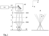
- FIG. 1 shows a schematic representation of an example of the proposed arrangement.
- Collimated laser radiation LS from a laser beam source LA is deflected by the deflection unit AE in two mutually perpendicular directions (X and Y directions).
- This deflection unit AE can be, for example, a two-dimensional galvanometer scanner.
- the figure shows three positions of one of the mirrors of the deflection unit AE with the resulting beam path of the laser radiation.
- the laser radiation strikes the first optical system OS1, in this example a focusing lens, at an angle to the optical axis.
- the laser radiation In the middle position of the mirror of the deflection unit AE shown, the laser radiation propagates along the optical axis through the first optical system OS1.
- An intermediate focus ZF is created at a distance b of the focal length of the first optical system OS1.
- the diverging laser radiation is then focused onto the workpiece W by the second optical system OS2.
- the second optical system OS2 is also formed solely by a focusing lens.
- the distances a, b, c and d between the deflection unit AE and the first optical system OS1, between the first optical system OS1 and the intermediate focus ZF, between the intermediate focus ZF and the second optical system OS2 and between the second optical system OS2 and the workpiece surface W, which in this example corresponds to the machining plane, are selected such that the laser beam crosses the optical axis before hitting the workpiece surface W.
- This is shown enlarged in the enlarged view of section A in the right-hand part of the figure.
- the offset of the laser beam from the center line or The optical axis which was created during the passage through the first optical system OS1 with the corresponding mirror position, leads to the laser beam being angled at an angle ⁇ and a helix point above the focal plane.
- the two optical systems OS1 and OS2 image a virtual point including a virtual deflection above the deflection unit AE, thus leading to an angle adjustment in a direction advantageous for the conicity of the desired bore.
- the desired hole By appropriately dynamically deflecting the laser beam LS with the deflection unit AE, the desired hole can be created.
- the angle of incidence on the workpiece surface is proportional to the offset of the laser beam between the two optical systems OS1, OS2 from the centerline or optical axis.
- both the proportionality factor and the focus diameter can be adjusted.
Landscapes
- Physics & Mathematics (AREA)
- Optics & Photonics (AREA)
- Engineering & Computer Science (AREA)
- Plasma & Fusion (AREA)
- Mechanical Engineering (AREA)
- Laser Beam Processing (AREA)
Claims (9)
- Agencement pour le traitement de matériaux avec un faisceau laser, notamment pour le perçage par faisceau laser, comportant- un dispositif de déviation dynamique (AE) pour le faisceau laser (LS), qui est conçu pour dévier le faisceau laser (LS) dans deux directions mutuellement perpendiculaires, et- un agencement optique, avec lequel un faisceau laser sortant du dispositif de déviation (AE) est focalisé sur un plan de traitement (W),- dans lequel l'agencement optique présente le long d'un axe optique de l'agencement optique un premier système optique (OS1) et un deuxième système optique (OS2), qui sont conçus et disposés de telle sorte que le faisceau laser (LS) forme entre le premier et le deuxième système optique (OS1, OS2) un foyer intermédiaire (ZF), caractérisé en ce que le faisceau laser croise l'axe optique lors de l'entrée dans le premier système optique (OS1) sous un angle par rapport à l'axe optique et espacé de celui-ci entre le deuxième système optique (OS2) et le plan de traitement (W).
- Agencement selon la revendication 1, caractérisé en ce qu'un ou plusieurs éléments de réglage sont fixés à un des deux systèmes optiques (OS1, OS2) ou aux deux systèmes optiques (OS1, OS2), avec lequel ou lesquels une distance entre les deux systèmes optiques (OS1, OS2) et/ou une distance du premier système optique (OS1) à l'unité de déviation (AE) et/ou une distance du deuxième système optique (OS2) au plan de traitement (W) peut être réglée ou modifiée.
- Dispositif selon la revendication 1 ou 2, caractérisé en ce que dans le trajet du faisceau laser (LS) devant le dispositif de déviation (AE) un télescope est disposé, avec lequel un diamètre de faisceau du faisceau laser (LS) peut être modifié.
- Dispositif selon la revendication 1 ou 2, caractérisé en ce qu'un dispositif optique de pré-focalisation du faisceau laser (LS) est disposé dans le trajet du faisceau laser (LS) devant l'agencement optique ou le dispositif de déviation (AE).
- Dispositif selon la revendication 4, caractérisé en ce que le dispositif optique de pré-focalisation est conçu de telle manière qu'il permettre une pré-focalisation variable du faisceau laser (LS).
- Dispositif selon une des revendications 1 à 5, caractérisé en ce que la disposition optique présente un ou plusieurs éléments de réglage, avec lequel ou lesquels un plan focal du faisceau laser (LS) peut être déplacé pendant le traitement du matériau le long de l'axe optique de l'agencement optique.
- Dispositif selon une des revendications 1 à 6, caractérisé en ce que l'agencement optique présente au moins un élément pour influencer la polarisation, ce qui permet de régler une polarisation avantageuse pour le traitement du matériau.
- Utilisation du dispositif selon une ou plusieurs des revendications précédentes pour la réalisation d'un trou de forage par enlèvement complet couche par couche, dans lequel une section transversale du trou de forage est entièrement traversée par le faisceau laser.
- Utilisation du dispositif selon une ou plusieurs des revendications précédentes pour réaliser un trou de forage en découpant un contour de trou de forage au moyen de mouvements en spirale ou circulaires avec le faisceau laser.
Applications Claiming Priority (2)
| Application Number | Priority Date | Filing Date | Title |
|---|---|---|---|
| DE102020201207.5A DE102020201207A1 (de) | 2020-01-31 | 2020-01-31 | Anordnung zur Materialbearbeitung mit einem Laserstrahl, insbesondere zum Laserstrahl-Bohren |
| PCT/EP2021/051977 WO2021152008A1 (fr) | 2020-01-31 | 2021-01-28 | Ensemble de traitement de matériau à l'aide d'un faisceau laser, notamment destiné au perçage par laser |
Publications (2)
| Publication Number | Publication Date |
|---|---|
| EP4096860A1 EP4096860A1 (fr) | 2022-12-07 |
| EP4096860B1 true EP4096860B1 (fr) | 2025-06-18 |
Family
ID=74586983
Family Applications (1)
| Application Number | Title | Priority Date | Filing Date |
|---|---|---|---|
| EP21704427.0A Active EP4096860B1 (fr) | 2020-01-31 | 2021-01-28 | Ensemble de traitement de matériau à l'aide d'un faisceau laser, notamment destiné au perçage par laser |
Country Status (7)
| Country | Link |
|---|---|
| US (1) | US12515279B2 (fr) |
| EP (1) | EP4096860B1 (fr) |
| JP (1) | JP7710452B2 (fr) |
| KR (1) | KR102860749B1 (fr) |
| CN (1) | CN115379922A (fr) |
| DE (1) | DE102020201207A1 (fr) |
| WO (1) | WO2021152008A1 (fr) |
Families Citing this family (1)
| Publication number | Priority date | Publication date | Assignee | Title |
|---|---|---|---|---|
| WO2025105196A1 (fr) * | 2023-11-13 | 2025-05-22 | デクセリアルズ株式会社 | Procédé de production de film individualisé, film individualisé, procédé de production de structure de connexion et structure de connexion |
Citations (2)
| Publication number | Priority date | Publication date | Assignee | Title |
|---|---|---|---|---|
| EP1082883B1 (fr) * | 1998-05-29 | 2002-10-16 | Exitech Limited | Dispositif permettant de forer des trous d'interconnexion microscopiques dans des blocs de connexion de circuit electrique et technique afferente |
| DE102005013949A1 (de) * | 2005-03-26 | 2006-09-28 | Carl Zeiss Meditec Ag | Scanvorrichtung |
Family Cites Families (35)
| Publication number | Priority date | Publication date | Assignee | Title |
|---|---|---|---|---|
| FR2437008B1 (fr) * | 1978-09-20 | 1985-06-28 | Philip Morris Inc | Appareil de production de faisceaux lumineux pulses |
| JP3216987B2 (ja) * | 1996-03-15 | 2001-10-09 | 三菱電機株式会社 | レーザ転写加工装置およびレーザ転写加工方法 |
| US6433303B1 (en) * | 2000-03-31 | 2002-08-13 | Matsushita Electric Industrial Co., Ltd. | Method and apparatus using laser pulses to make an array of microcavity holes |
| DE10045973A1 (de) | 2000-09-16 | 2002-04-04 | Bosch Gmbh Robert | Optische Vorrichtung zum Bohren mittels Laserstrahl |
| DE10054853A1 (de) * | 2000-11-06 | 2002-08-01 | Bosch Gmbh Robert | Verfahren zum Einbringen eines Mikrolochs in ein vorzugsweise metallisches Werkstück und Vorrichtung hierzu |
| JP4069348B2 (ja) * | 2001-02-22 | 2008-04-02 | トヨタ自動車株式会社 | レーザ加工方法およびレーザ加工装置 |
| US6803539B2 (en) | 2002-07-25 | 2004-10-12 | Matsushita Electrical Industrial Co., Ltd. | System and method of aligning a microfilter in a laser drilling system using a CCD camera |
| JP2004261822A (ja) * | 2003-02-28 | 2004-09-24 | Fine Device:Kk | レーザ加工装置 |
| JP2004337925A (ja) * | 2003-05-15 | 2004-12-02 | Mitsubishi Electric Corp | レーザ加工機 |
| US8237082B2 (en) * | 2004-09-02 | 2012-08-07 | Siemens Aktiengesellschaft | Method for producing a hole |
| US20080013182A1 (en) * | 2006-07-17 | 2008-01-17 | Joerg Ferber | Two-stage laser-beam homogenizer |
| US20090312859A1 (en) * | 2008-06-16 | 2009-12-17 | Electro Scientific Industries, Inc. | Modifying entry angles associated with circular tooling actions to improve throughput in part machining |
| KR101057458B1 (ko) * | 2008-11-03 | 2011-08-17 | 주식회사 이오테크닉스 | 드릴링 장치 및 드릴링 방법 |
| US8338745B2 (en) * | 2009-12-07 | 2012-12-25 | Panasonic Corporation | Apparatus and methods for drilling holes with no taper or reverse taper |
| US8525073B2 (en) * | 2010-01-27 | 2013-09-03 | United Technologies Corporation | Depth and breakthrough detection for laser machining |
| DE202010006047U1 (de) | 2010-04-22 | 2010-07-22 | Trumpf Werkzeugmaschinen Gmbh + Co. Kg | Strahlformungseinheit zur Fokussierung eines Laserstrahls |
| DE102011006085A1 (de) | 2011-03-25 | 2012-09-27 | Carl Zeiss Meditec Ag | Ophthalmologisches Gerät |
| JP5758237B2 (ja) * | 2011-09-01 | 2015-08-05 | 株式会社豊田中央研究所 | レーザ加工装置及びレーザ加工方法 |
| JP5994723B2 (ja) * | 2013-05-09 | 2016-09-21 | トヨタ自動車株式会社 | レーザ穴あけ加工方法および装置 |
| JP2017530867A (ja) * | 2014-07-14 | 2017-10-19 | コーニング インコーポレイテッド | 長さおよび直径の調節可能なレーザビーム焦線を用いて透明材料を加工するためのシステムおよび方法 |
| GB2529808B (en) * | 2014-08-26 | 2018-07-25 | M Solv Ltd | Apparatus and methods for performing laser ablation on a substrate |
| KR101527482B1 (ko) * | 2014-11-25 | 2015-06-10 | 유수영 | 레이저를 이용한 미세 부품 가공 장치 |
| US9873628B1 (en) * | 2014-12-02 | 2018-01-23 | Coherent Kaiserslautern GmbH | Filamentary cutting of brittle materials using a picosecond pulsed laser |
| KR102781391B1 (ko) * | 2015-09-09 | 2025-03-17 | 일렉트로 싸이언티픽 인더스트리이즈 인코포레이티드 | 작업물들을 레이저 가공하기 위한 레이저 가공 장치, 방법들 및 관련된 배열들 |
| CN105436703A (zh) | 2015-12-30 | 2016-03-30 | 常州英诺激光科技有限公司 | 一种适用于硬脆基板的激光钻微孔设备及方法 |
| JP6616368B2 (ja) * | 2017-09-14 | 2019-12-04 | ファナック株式会社 | レーザ加工前に光学系の汚染レベルに応じて加工条件を補正するレーザ加工装置 |
| WO2019064325A1 (fr) * | 2017-09-26 | 2019-04-04 | 三菱電機株式会社 | Procédé de traitement laser et dispositif de traitement laser |
| US20190151993A1 (en) * | 2017-11-22 | 2019-05-23 | Asm Technology Singapore Pte Ltd | Laser-cutting using selective polarization |
| KR102748612B1 (ko) * | 2018-03-23 | 2025-01-02 | 로렌스 리버모어 내셔널 시큐리티, 엘엘씨 | 게이트형 cw 및 쇼트 펄스 레이저를 사용한 레이저 드릴링 및 기계 가공 향상 |
| DE102018208752B4 (de) | 2018-06-04 | 2024-08-22 | Fraunhofer-Gesellschaft zur Förderung der angewandten Forschung e.V. | Vorrichtung und Verfahren zur Bearbeitung zur Bearbeitung schwer zugänglicher Werkstücke sowie Verwendung einer Vorrichtung |
| CN108890151A (zh) * | 2018-07-19 | 2018-11-27 | 深圳市吉祥云科技有限公司 | 一种光伏玻璃打孔方法 |
| TWI866446B (zh) * | 2018-10-08 | 2024-12-11 | 美商伊雷克托科學工業股份有限公司 | 用於在基板中形成穿孔的方法 |
| CN109530913B (zh) * | 2018-12-25 | 2021-07-23 | 武汉华工激光工程有限责任公司 | 一种贝塞尔光束的激光加工优化方法及系统 |
| TWI843784B (zh) * | 2019-01-31 | 2024-06-01 | 美商伊雷克托科學工業股份有限公司 | 雷射加工設備、與設備一起使用的控制器及非暫時性電腦可讀取媒體 |
| CN110449731B (zh) * | 2019-08-27 | 2023-07-04 | 华中科技大学 | 一种激光变锥变径旋切孔加工光学系统 |
-
2020
- 2020-01-31 DE DE102020201207.5A patent/DE102020201207A1/de active Pending
-
2021
- 2021-01-28 EP EP21704427.0A patent/EP4096860B1/fr active Active
- 2021-01-28 US US17/796,444 patent/US12515279B2/en active Active
- 2021-01-28 KR KR1020227026462A patent/KR102860749B1/ko active Active
- 2021-01-28 CN CN202180011782.7A patent/CN115379922A/zh active Pending
- 2021-01-28 JP JP2022545969A patent/JP7710452B2/ja active Active
- 2021-01-28 WO PCT/EP2021/051977 patent/WO2021152008A1/fr not_active Ceased
Patent Citations (2)
| Publication number | Priority date | Publication date | Assignee | Title |
|---|---|---|---|---|
| EP1082883B1 (fr) * | 1998-05-29 | 2002-10-16 | Exitech Limited | Dispositif permettant de forer des trous d'interconnexion microscopiques dans des blocs de connexion de circuit electrique et technique afferente |
| DE102005013949A1 (de) * | 2005-03-26 | 2006-09-28 | Carl Zeiss Meditec Ag | Scanvorrichtung |
Also Published As
| Publication number | Publication date |
|---|---|
| DE102020201207A1 (de) | 2021-08-05 |
| EP4096860A1 (fr) | 2022-12-07 |
| WO2021152008A1 (fr) | 2021-08-05 |
| US12515279B2 (en) | 2026-01-06 |
| JP2023512236A (ja) | 2023-03-24 |
| CN115379922A (zh) | 2022-11-22 |
| US20230339047A1 (en) | 2023-10-26 |
| JP7710452B2 (ja) | 2025-07-18 |
| KR20220130714A (ko) | 2022-09-27 |
| KR102860749B1 (ko) | 2025-09-16 |
Similar Documents
| Publication | Publication Date | Title |
|---|---|---|
| EP2673106B1 (fr) | Dispositif, sytème et méthode pour la texturation de pièces plates par interférences lumineuses | |
| DE3934587C2 (de) | Verfahren zum Herstellen von mittels Laserstrahlung erzeugter, hochpräziser Durchgangsbohrungen in Werkstücken | |
| EP2976176B1 (fr) | Méthode et dispositif pour former une surface structurée au moyen d'un faisceau laser | |
| EP2596899B1 (fr) | Dispositif et procédé de structuration par interférences d'échantillons plats | |
| EP4200101B1 (fr) | Procédé de production d'au moins une partie de pièce à usiner et d'une pièce à usiner résiduelle à partir d'une pièce à usiner | |
| DE202008017745U1 (de) | Vorrichtung zum Führen eines Lichtstrahls | |
| EP3965990B1 (fr) | Procédé et dispositif de traitement au laser d'une pièce | |
| EP3154740B1 (fr) | Dispositif d'usinage de matériaux par laser à unité à déplacement parallèle | |
| WO2001039920A1 (fr) | Dispositif pour usiner des substrats et procede mis en oeuvre a l'aide dudit dispositif | |
| EP4238687B1 (fr) | Procédé d'usinage d'une pièce à usiner en forme de plaque ou de tube | |
| WO2000030802A1 (fr) | Dispositif et procede d'exploration de la surface d'un objet a l'aide d'un faisceau laser | |
| DE102020205948A1 (de) | Laserschneidverfahren und Laserschneidanlage | |
| DE10054853A1 (de) | Verfahren zum Einbringen eines Mikrolochs in ein vorzugsweise metallisches Werkstück und Vorrichtung hierzu | |
| DE19817851C1 (de) | Verfahren zum Ablenken eines Laserstrahls | |
| DE102014206358A1 (de) | Verfahren und Laserschneidmaschine zum Laserschneiden kleiner Öffnungen | |
| EP4096860B1 (fr) | Ensemble de traitement de matériau à l'aide d'un faisceau laser, notamment destiné au perçage par laser | |
| EP1291117B1 (fr) | Méthode pour produire un perçage dans une pièce à l'aide d'un faisceau laser | |
| DE102017105955A1 (de) | Laserschleifvorrichtung sowie Verfahren zum Bearbeiten eines Werkstückes | |
| DE102015112151A1 (de) | Verfahren und Vorrichtung zur Laserbearbeitung eines Substrates mit mehrfacher Ablenkung einer Laserstrahlung | |
| DE102004050047A1 (de) | Verfahren und Vorrichtung zur Erzeugung von Bohrungen mittels Laser | |
| EP0683007B1 (fr) | Dispositif d'usinage | |
| DE10140533A1 (de) | Verfahren und Vorrichtung zur Mikrobearbeitung eines Werkstücks mit Laserstrahlung | |
| WO2006000549A1 (fr) | Machine d'usinage au laser pour percer des trous dans une piece, avec un dispositif de deviation optique et une unite de deflexion | |
| DE4202941C2 (de) | Verfahren zum Materialabtrag an einem bewegten Werkstück | |
| DE102022204685B3 (de) | Optik zur Erzeugung eines linearen Fokus, Vorrichtung und Verfahren zur Bearbeitung eines Werkstücks |
Legal Events
| Date | Code | Title | Description |
|---|---|---|---|
| STAA | Information on the status of an ep patent application or granted ep patent |
Free format text: STATUS: UNKNOWN |
|
| STAA | Information on the status of an ep patent application or granted ep patent |
Free format text: STATUS: THE INTERNATIONAL PUBLICATION HAS BEEN MADE |
|
| PUAI | Public reference made under article 153(3) epc to a published international application that has entered the european phase |
Free format text: ORIGINAL CODE: 0009012 |
|
| STAA | Information on the status of an ep patent application or granted ep patent |
Free format text: STATUS: REQUEST FOR EXAMINATION WAS MADE |
|
| 17P | Request for examination filed |
Effective date: 20220811 |
|
| AK | Designated contracting states |
Kind code of ref document: A1 Designated state(s): AL AT BE BG CH CY CZ DE DK EE ES FI FR GB GR HR HU IE IS IT LI LT LU LV MC MK MT NL NO PL PT RO RS SE SI SK SM TR |
|
| DAV | Request for validation of the european patent (deleted) | ||
| DAX | Request for extension of the european patent (deleted) | ||
| GRAP | Despatch of communication of intention to grant a patent |
Free format text: ORIGINAL CODE: EPIDOSNIGR1 |
|
| STAA | Information on the status of an ep patent application or granted ep patent |
Free format text: STATUS: GRANT OF PATENT IS INTENDED |
|
| INTG | Intention to grant announced |
Effective date: 20250203 |
|
| GRAS | Grant fee paid |
Free format text: ORIGINAL CODE: EPIDOSNIGR3 |
|
| GRAA | (expected) grant |
Free format text: ORIGINAL CODE: 0009210 |
|
| STAA | Information on the status of an ep patent application or granted ep patent |
Free format text: STATUS: THE PATENT HAS BEEN GRANTED |
|
| AK | Designated contracting states |
Kind code of ref document: B1 Designated state(s): AL AT BE BG CH CY CZ DE DK EE ES FI FR GB GR HR HU IE IS IT LI LT LU LV MC MK MT NL NO PL PT RO RS SE SI SK SM TR |
|
| REG | Reference to a national code |
Ref country code: GB Ref legal event code: FG4D Free format text: NOT ENGLISH |
|
| REG | Reference to a national code |
Ref country code: CH Ref legal event code: EP |
|
| REG | Reference to a national code |
Ref country code: DE Ref legal event code: R096 Ref document number: 502021007777 Country of ref document: DE |
|
| REG | Reference to a national code |
Ref country code: CH Ref legal event code: EP |
|
| REG | Reference to a national code |
Ref country code: IE Ref legal event code: FG4D Free format text: LANGUAGE OF EP DOCUMENT: GERMAN |
|
| PG25 | Lapsed in a contracting state [announced via postgrant information from national office to epo] |
Ref country code: FI Free format text: LAPSE BECAUSE OF FAILURE TO SUBMIT A TRANSLATION OF THE DESCRIPTION OR TO PAY THE FEE WITHIN THE PRESCRIBED TIME-LIMIT Effective date: 20250618 |
|
| REG | Reference to a national code |
Ref country code: LT Ref legal event code: MG9D |
|
| PG25 | Lapsed in a contracting state [announced via postgrant information from national office to epo] |
Ref country code: NO Free format text: LAPSE BECAUSE OF FAILURE TO SUBMIT A TRANSLATION OF THE DESCRIPTION OR TO PAY THE FEE WITHIN THE PRESCRIBED TIME-LIMIT Effective date: 20250918 Ref country code: GR Free format text: LAPSE BECAUSE OF FAILURE TO SUBMIT A TRANSLATION OF THE DESCRIPTION OR TO PAY THE FEE WITHIN THE PRESCRIBED TIME-LIMIT Effective date: 20250919 |
|
| PG25 | Lapsed in a contracting state [announced via postgrant information from national office to epo] |
Ref country code: BG Free format text: LAPSE BECAUSE OF FAILURE TO SUBMIT A TRANSLATION OF THE DESCRIPTION OR TO PAY THE FEE WITHIN THE PRESCRIBED TIME-LIMIT Effective date: 20250618 |
|
| PG25 | Lapsed in a contracting state [announced via postgrant information from national office to epo] |
Ref country code: HR Free format text: LAPSE BECAUSE OF FAILURE TO SUBMIT A TRANSLATION OF THE DESCRIPTION OR TO PAY THE FEE WITHIN THE PRESCRIBED TIME-LIMIT Effective date: 20250618 |
|
| PG25 | Lapsed in a contracting state [announced via postgrant information from national office to epo] |
Ref country code: RS Free format text: LAPSE BECAUSE OF FAILURE TO SUBMIT A TRANSLATION OF THE DESCRIPTION OR TO PAY THE FEE WITHIN THE PRESCRIBED TIME-LIMIT Effective date: 20250918 |
|
| REG | Reference to a national code |
Ref country code: NL Ref legal event code: MP Effective date: 20250618 |
|
| PG25 | Lapsed in a contracting state [announced via postgrant information from national office to epo] |
Ref country code: LV Free format text: LAPSE BECAUSE OF FAILURE TO SUBMIT A TRANSLATION OF THE DESCRIPTION OR TO PAY THE FEE WITHIN THE PRESCRIBED TIME-LIMIT Effective date: 20250618 |
|
| PG25 | Lapsed in a contracting state [announced via postgrant information from national office to epo] |
Ref country code: NL Free format text: LAPSE BECAUSE OF FAILURE TO SUBMIT A TRANSLATION OF THE DESCRIPTION OR TO PAY THE FEE WITHIN THE PRESCRIBED TIME-LIMIT Effective date: 20250618 |
|
| PG25 | Lapsed in a contracting state [announced via postgrant information from national office to epo] |
Ref country code: PT Free format text: LAPSE BECAUSE OF FAILURE TO SUBMIT A TRANSLATION OF THE DESCRIPTION OR TO PAY THE FEE WITHIN THE PRESCRIBED TIME-LIMIT Effective date: 20251020 |
|
| PG25 | Lapsed in a contracting state [announced via postgrant information from national office to epo] |
Ref country code: IS Free format text: LAPSE BECAUSE OF FAILURE TO SUBMIT A TRANSLATION OF THE DESCRIPTION OR TO PAY THE FEE WITHIN THE PRESCRIBED TIME-LIMIT Effective date: 20251018 |
|
| PG25 | Lapsed in a contracting state [announced via postgrant information from national office to epo] |
Ref country code: SM Free format text: LAPSE BECAUSE OF FAILURE TO SUBMIT A TRANSLATION OF THE DESCRIPTION OR TO PAY THE FEE WITHIN THE PRESCRIBED TIME-LIMIT Effective date: 20250618 |
|
| PG25 | Lapsed in a contracting state [announced via postgrant information from national office to epo] |
Ref country code: CZ Free format text: LAPSE BECAUSE OF FAILURE TO SUBMIT A TRANSLATION OF THE DESCRIPTION OR TO PAY THE FEE WITHIN THE PRESCRIBED TIME-LIMIT Effective date: 20250618 |
|
| PG25 | Lapsed in a contracting state [announced via postgrant information from national office to epo] |
Ref country code: PL Free format text: LAPSE BECAUSE OF FAILURE TO SUBMIT A TRANSLATION OF THE DESCRIPTION OR TO PAY THE FEE WITHIN THE PRESCRIBED TIME-LIMIT Effective date: 20250618 |
|
| PG25 | Lapsed in a contracting state [announced via postgrant information from national office to epo] |
Ref country code: EE Free format text: LAPSE BECAUSE OF FAILURE TO SUBMIT A TRANSLATION OF THE DESCRIPTION OR TO PAY THE FEE WITHIN THE PRESCRIBED TIME-LIMIT Effective date: 20250618 |
|
| PG25 | Lapsed in a contracting state [announced via postgrant information from national office to epo] |
Ref country code: SK Free format text: LAPSE BECAUSE OF FAILURE TO SUBMIT A TRANSLATION OF THE DESCRIPTION OR TO PAY THE FEE WITHIN THE PRESCRIBED TIME-LIMIT Effective date: 20250618 |
|
| PG25 | Lapsed in a contracting state [announced via postgrant information from national office to epo] |
Ref country code: ES Free format text: LAPSE BECAUSE OF FAILURE TO SUBMIT A TRANSLATION OF THE DESCRIPTION OR TO PAY THE FEE WITHIN THE PRESCRIBED TIME-LIMIT Effective date: 20250618 |
|
| P01 | Opt-out of the competence of the unified patent court (upc) registered |
Free format text: CASE NUMBER: UPC_APP_0006342_4096860/2026 Effective date: 20260220 |
|
| PG25 | Lapsed in a contracting state [announced via postgrant information from national office to epo] |
Ref country code: DK Free format text: LAPSE BECAUSE OF FAILURE TO SUBMIT A TRANSLATION OF THE DESCRIPTION OR TO PAY THE FEE WITHIN THE PRESCRIBED TIME-LIMIT Effective date: 20250618 |
|
| PGFP | Annual fee paid to national office [announced via postgrant information from national office to epo] |
Ref country code: DE Payment date: 20260120 Year of fee payment: 6 |
|
| PG25 | Lapsed in a contracting state [announced via postgrant information from national office to epo] |
Ref country code: IT Free format text: LAPSE BECAUSE OF FAILURE TO SUBMIT A TRANSLATION OF THE DESCRIPTION OR TO PAY THE FEE WITHIN THE PRESCRIBED TIME-LIMIT Effective date: 20250618 |
|
| PLBE | No opposition filed within time limit |
Free format text: ORIGINAL CODE: 0009261 |
|
| STAA | Information on the status of an ep patent application or granted ep patent |
Free format text: STATUS: NO OPPOSITION FILED WITHIN TIME LIMIT |