EP3933423B1 - Methode zum testen einer oder mehrerer mikrobatterievorrichtungen und system zur durchführung dieser testmethode - Google Patents
Methode zum testen einer oder mehrerer mikrobatterievorrichtungen und system zur durchführung dieser testmethode Download PDFInfo
- Publication number
- EP3933423B1 EP3933423B1 EP21181069.2A EP21181069A EP3933423B1 EP 3933423 B1 EP3933423 B1 EP 3933423B1 EP 21181069 A EP21181069 A EP 21181069A EP 3933423 B1 EP3933423 B1 EP 3933423B1
- Authority
- EP
- European Patent Office
- Prior art keywords
- voltage
- testing
- time
- order
- anode
- Prior art date
- Legal status (The legal status is an assumption and is not a legal conclusion. Google has not performed a legal analysis and makes no representation as to the accuracy of the status listed.)
- Active
Links
Images

Classifications
-
- G—PHYSICS
- G01—MEASURING; TESTING
- G01R—MEASURING ELECTRIC VARIABLES; MEASURING MAGNETIC VARIABLES
- G01R31/00—Arrangements for testing electric properties; Arrangements for locating electric faults; Arrangements for electrical testing characterised by what is being tested not provided for elsewhere
- G01R31/36—Arrangements for testing, measuring or monitoring the electrical condition of accumulators or electric batteries, e.g. capacity or state of charge [SoC]
- G01R31/385—Arrangements for measuring battery or accumulator variables
-
- G—PHYSICS
- G01—MEASURING; TESTING
- G01R—MEASURING ELECTRIC VARIABLES; MEASURING MAGNETIC VARIABLES
- G01R31/00—Arrangements for testing electric properties; Arrangements for locating electric faults; Arrangements for electrical testing characterised by what is being tested not provided for elsewhere
- G01R31/36—Arrangements for testing, measuring or monitoring the electrical condition of accumulators or electric batteries, e.g. capacity or state of charge [SoC]
- G01R31/382—Arrangements for monitoring battery or accumulator variables, e.g. SoC
- G01R31/3835—Arrangements for monitoring battery or accumulator variables, e.g. SoC involving only voltage measurements
-
- G—PHYSICS
- G01—MEASURING; TESTING
- G01R—MEASURING ELECTRIC VARIABLES; MEASURING MAGNETIC VARIABLES
- G01R31/00—Arrangements for testing electric properties; Arrangements for locating electric faults; Arrangements for electrical testing characterised by what is being tested not provided for elsewhere
- G01R31/36—Arrangements for testing, measuring or monitoring the electrical condition of accumulators or electric batteries, e.g. capacity or state of charge [SoC]
- G01R31/3644—Constructional arrangements
- G01R31/3648—Constructional arrangements comprising digital calculation means, e.g. for performing an algorithm
-
- G—PHYSICS
- G01—MEASURING; TESTING
- G01R—MEASURING ELECTRIC VARIABLES; MEASURING MAGNETIC VARIABLES
- G01R31/00—Arrangements for testing electric properties; Arrangements for locating electric faults; Arrangements for electrical testing characterised by what is being tested not provided for elsewhere
- G01R31/36—Arrangements for testing, measuring or monitoring the electrical condition of accumulators or electric batteries, e.g. capacity or state of charge [SoC]
- G01R31/385—Arrangements for measuring battery or accumulator variables
- G01R31/3865—Arrangements for measuring battery or accumulator variables related to manufacture, e.g. testing after manufacture
-
- G—PHYSICS
- G01—MEASURING; TESTING
- G01R—MEASURING ELECTRIC VARIABLES; MEASURING MAGNETIC VARIABLES
- G01R31/00—Arrangements for testing electric properties; Arrangements for locating electric faults; Arrangements for electrical testing characterised by what is being tested not provided for elsewhere
- G01R31/36—Arrangements for testing, measuring or monitoring the electrical condition of accumulators or electric batteries, e.g. capacity or state of charge [SoC]
- G01R31/389—Measuring internal impedance, internal conductance or related variables
-
- H—ELECTRICITY
- H01—ELECTRIC ELEMENTS
- H01M—PROCESSES OR MEANS, e.g. BATTERIES, FOR THE DIRECT CONVERSION OF CHEMICAL ENERGY INTO ELECTRICAL ENERGY
- H01M10/00—Secondary cells; Manufacture thereof
- H01M10/42—Methods or arrangements for servicing or maintenance of secondary cells or secondary half-cells
- H01M10/4285—Testing apparatus
-
- H—ELECTRICITY
- H01—ELECTRIC ELEMENTS
- H01M—PROCESSES OR MEANS, e.g. BATTERIES, FOR THE DIRECT CONVERSION OF CHEMICAL ENERGY INTO ELECTRICAL ENERGY
- H01M10/00—Secondary cells; Manufacture thereof
- H01M10/05—Accumulators with non-aqueous electrolyte
- H01M10/052—Li-accumulators
-
- H—ELECTRICITY
- H01—ELECTRIC ELEMENTS
- H01M—PROCESSES OR MEANS, e.g. BATTERIES, FOR THE DIRECT CONVERSION OF CHEMICAL ENERGY INTO ELECTRICAL ENERGY
- H01M10/00—Secondary cells; Manufacture thereof
- H01M10/05—Accumulators with non-aqueous electrolyte
- H01M10/056—Accumulators with non-aqueous electrolyte characterised by the materials used as electrolytes, e.g. mixed inorganic/organic electrolytes
- H01M10/0561—Accumulators with non-aqueous electrolyte characterised by the materials used as electrolytes, e.g. mixed inorganic/organic electrolytes the electrolyte being constituted of inorganic materials only
- H01M10/0562—Solid materials
-
- Y—GENERAL TAGGING OF NEW TECHNOLOGICAL DEVELOPMENTS; GENERAL TAGGING OF CROSS-SECTIONAL TECHNOLOGIES SPANNING OVER SEVERAL SECTIONS OF THE IPC; TECHNICAL SUBJECTS COVERED BY FORMER USPC CROSS-REFERENCE ART COLLECTIONS [XRACs] AND DIGESTS
- Y02—TECHNOLOGIES OR APPLICATIONS FOR MITIGATION OR ADAPTATION AGAINST CLIMATE CHANGE
- Y02E—REDUCTION OF GREENHOUSE GAS [GHG] EMISSIONS, RELATED TO ENERGY GENERATION, TRANSMISSION OR DISTRIBUTION
- Y02E60/00—Enabling technologies; Technologies with a potential or indirect contribution to GHG emissions mitigation
- Y02E60/10—Energy storage using batteries
-
- Y—GENERAL TAGGING OF NEW TECHNOLOGICAL DEVELOPMENTS; GENERAL TAGGING OF CROSS-SECTIONAL TECHNOLOGIES SPANNING OVER SEVERAL SECTIONS OF THE IPC; TECHNICAL SUBJECTS COVERED BY FORMER USPC CROSS-REFERENCE ART COLLECTIONS [XRACs] AND DIGESTS
- Y02—TECHNOLOGIES OR APPLICATIONS FOR MITIGATION OR ADAPTATION AGAINST CLIMATE CHANGE
- Y02P—CLIMATE CHANGE MITIGATION TECHNOLOGIES IN THE PRODUCTION OR PROCESSING OF GOODS
- Y02P70/00—Climate change mitigation technologies in the production process for final industrial or consumer products
- Y02P70/50—Manufacturing or production processes characterised by the final manufactured product
Definitions
- the field of the invention is that of the electrical testing of electronic or technological devices produced using microelectronic technology: integrated circuits, sensors, elementary devices (resistance, diode, capacitance, etc.).
- micro-energy storage components commonly called microbatteries.
- a microbattery is made by successive deposition on a substrate of (i) first current collector, (ii) first electrode, (iii) electrolyte, (iv) second electrode, and (v) second current collector. Encapsulation by means of deposition of additional layers, or by transfer of a cap is necessary to protect the device from chemical reactivity with oxygen and water vapor.
- the latter configuration is the most advantageous in the case of integrating microbatteries on silicon substrates and using micro-fabrication techniques: it offers the presence of lithium metal (the most efficient anode in terms of energy density, potential and cyclability) without the disadvantages associated with its presence during the process (sensitivity to air, incompatibility with etching and photolithography solutions).
- the most widely used and reliable electrical sorting and testing protocol consists of (i) testing the microbattery over several complete charge and discharge cycles (going from fully charged to fully discharged) and (ii) comparing the capacity values, voltage profiles and internal resistance to reference values.
- the challenge of sorting in this specific case is to be able to have electrical parameters that can be used to classify microbatteries including those in "Li-free” without having to carry out cycling, at the risk of not being able to sort until after the end of the manufacturing process.
- sorting on the basis of cycling requires that the microbattery be encapsulated, either at the plate level or after cutting and placing in a case, in order to avoid structural changes and sensitivity to air linked to the presence of metallic lithium.
- Intermediate sorting to reduce manufacturing costs and identify failure modes is not possible, and this is what we are trying to achieve in this specific case.
- the document US9209496 proposes a sorting method consisting of measuring the open circuit voltage or OCV (for Open Circuit Voltage) of a battery, discharging it for a certain period and comparing the end of discharge potential with that of the OCV. It is clear that in the case of "Li-free” microbatteries, this sorting method is not suitable since (i) the OCV does not provide any information concerning the state of the battery, and (ii) the discharge of "Li-free” batteries does not allow their potential to be modified in a stable way since the microbattery is completely discharged at the time of the test.
- OCV Open Circuit Voltage
- the document US6526361 proposes a sorting method consisting of applying several successive pulses (either a current pulse application or a voltage pulse application) with a relaxation period between each pulse to batteries, measuring the associated voltage response and sorting based on this response. This approach is not applicable to "Li-free" type microbatteries since it requires a stable initial voltage state.
- the present invention relates to a test method particularly well suited to "Li-Free" type microbatteries, for which the methods of the prior art are not compatible.
- This method makes it possible to carry out non-degrading and rapid tests, and this method can also be applied to one or a plurality of devices tested in parallel.
- the durations ⁇ tbi are of the order of 10 seconds, the times Tbi being of the order of 0.1 second.
- the first thickness is of the order of a few nanometers and preferably 1 to 2 nanometers.
- the durations ⁇ tci are of the order of 50 seconds, the times Tci being of the order of 1 second.
- the second thickness is less than 10 nanometers and preferably equal to 5 nanometers.
- the durations ⁇ tdi are of the order of 10 seconds, the times Tdi being of the order of 1 second.
- the current generator is programmable and the voltmeter is programmable.
- the controller comprises a stopwatch, a memory and a processor.
- test system is such that each controller or the central controller comprises a timer, a memory and a processor.
- the test system of the invention may comprise a central controller comprising a memory, each controller managing the test phases for each test system, recording the voltage measurement results in its memory, the central controller retrieving said measurement results to record them in its memory.
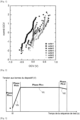
- FIG 1 illustrates the variations of the OCV for a microbattery type component produced on a batch of 7 wafers, and more precisely a Henry diagram, in which the ordinate is the Normit function of x, described in detail in the document accessible via the link: http://www.modulad.fr/numero-35/Excelense-grenier-35/DiagrammedeHenry.pdf;
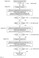
- FIG. 1 illustrates the evolution of the voltage at the terminals of a microbattery device as a function of time during all the steps of the test method according to the invention
- FIG. 3 illustrates a flowchart comprising all the successive test phases in the test method according to the invention
- FIG 4 illustrates an exemplary system for testing a plurality of micro-energy storage devices according to the invention, each device being connected to a controller;
- FIG 5 illustrates an example of a system for testing a plurality of micro-energy storage devices according to the invention, each device being connected to the same central controller.
- test method proposed in the present invention aims to overcome the various aforementioned drawbacks by using a non-degrading and rapid test technique.
- this technique can be applied to one or a plurality of devices tested in parallel.
- test method of the invention uses the test sequence described below, linking the different steps after validation of a criterion in the previous step, thus making it possible to conclude as soon as possible on a faulty device.
- the micro-energy storage device is hereinafter referred to as a microbattery.
- lithium-based microbattery comprising a metal anode which may be made of metal, for example titanium, and comprises a solid electrolyte which may be made of LiPON (English term: Lithium Phosphorus Oxynitride) and a cathode which may be made of LiCoO 2 , for example.
- a metal anode which may be made of metal, for example titanium
- a solid electrolyte which may be made of LiPON (English term: Lithium Phosphorus Oxynitride) and a cathode which may be made of LiCoO 2 , for example.
- This technique is advantageous because it applies four phases for each device tested which are triggered one after the other when a validation criterion is met. These four phases detailed below are called, initial voltage measurement phase OCV, charging phase, stabilization phase and retention phase.
- OCV initial voltage measurement phase
- charging phase charging phase
- stabilization phase retention phase.
- the figure 2 illustrates the sequence of these phases by showing the evolution of the voltage at the terminals of the device tested as a function of time in an example of a method described in more detail below.
- the test system is implemented on a device or the plurality of test systems can be implemented in parallel on a set of devices.
- the means used to implement the test method of the invention can be, according to a first variant of the invention, the following means and this for the test of each device Dn , only one of these devices Dn being represented in figure 4 .
- These means include a programmable current generator An , a programmable voltmeter Vn and a controller Cn .
- the device An has an anode connection Dn-Anode and a cathode connection Dn-cathode , the generator An : a positive connection An-H and a negative connection An-L, the voltmeter: a positive connection Vn-H and a negative connection Vn-L.
- the test method is to perform the microbattery device test by connecting the connections An-H of the current generator, Vn-H of the voltmeter and Dn-Anode of the microbattery device together, the connections An-L of the current generator, Vn-L of the voltmeter and Dn-Cathode of the same microbattery device together.
- This basic system can be repeated a plurality of times to test a plurality of devices.
- Each basic system can be controlled by a controller Cn comprising a processor Pn , a timer Crn and a memory Mn , this controller is connected to each voltmeter Vn and each current generator An and becomes an integral part of this system as also shown in the figure. figure 4 ; in this case all the controllers Cn of the plurality of test systems are themselves connected to a central controller Cc to control all the test systems.
- This configuration is advantageous insofar as the algorithm used has better flexibility and simpler implementation.
- the plurality of systems can be controlled by a central controller Cc comprising a timer Crc and a memory Mc connected to all the voltmeters Vn and to all the current generators An as shown in figure 5 .
- control means can be provided either by a central controller or by a set of individual controllers.
- the controller used has in its memory Mn or Mc , the characteristic times at which the voltage measurements are made by the voltmeters Vn and the time measurements by the chronometers Crn or the chronometer Crc.
- the controller used records these time and voltage measurements in its memory Mn or Mc.
- the central controller Cc In the case where there is only the central controller Cc, it manages the test sequences for the plurality of test systems and records the measurement results in its memory Mc ; in the case where there is a controller Cn associated with each test system, each controller Cn manages the test sequence for each test system, it records the measurement results in its memory Mn , then the central controller retrieves all the measurement results and saves them in its Mc memory.
- the test method according to the invention begins with a first phase Ph-a comprising the measurement of the initial voltage OCV of each device using the voltmeter Vn connected to each device, each of these measurements is recorded in the memory Mn of each controller Cn of each system, or in the memory Mc of the Central control Cc.
- This first phase makes it possible, for example, to obtain the OCV (Open Circuit Voltage) parameter of each device, from the measurement of this voltage at time t0. Only the measurement of a value equal to zero is useful in the case of "Li-free" microbatteries, because it signifies a failure in short-circuit mode and makes it possible to stop the tests for the components concerned.
- Phase Ph-a taken up on the flowchart of the figure 3 illustrates this first phase which can be conclusive and stop the test on a faulty device.
- each current generator An connected to each device Dn applies a current Ib to each device from a time t0.
- This current makes it possible to charge a minimal part of the device, which has the effect of not damaging the device. More specifically, this operation consists in initiating the migration of Li+ ions, and forming a continuous nanometric thickness (for example 1 to 2 nm) of lithium in the anode, and consequently the transition from a "Li-free" configuration to metallic Li, without structural impact on the component, which makes it possible to ensure both the relevance of the sorting a posteriori as well as the possibility of doing this sorting at any time during the manufacturing process.
- This second phase allows for example to obtain the Vb parameter by extracting the max voltage obtained from the measurements recorded during this phase.
- the components are considered compliant if the Vb voltage is located in an interval V bmin -V bmax defined according to the architecture of the component.
- the interval V bmin -V bmax is essentially defined by the redox couple in play, more specifically by the potential of the cathode (or positive electrode) with respect to a metallic lithium electrode.
- this interval will correspond to 3.85-3.89V
- Li4Ti5O12 cathode this interval will correspond to 1.4-1.6V.
- the Ph-b phase taken from the flow chart of the figure 3 illustrates this second phase which can be conclusive and allow continue or stop the test if the device does not meet the expected values and is considered non-compliant.
- each current generator An connected to each device Dn continues to apply a current lc (which can be equal to Ib ) to each device Dn.
- This step aims to adjust the thickness of the nanometric Li layer in relation to the needs of the electrical tests.
- the maximum sufficient thickness can typically be less than 10 nm, and preferably less than 5 nm. It should be noted that the total thickness of metallic lithium that will be used in the case of a complete cycling corresponds to 5000 nm, the proportion used for the test is approximately 1/1000th.
- This third phase allows for example to obtain the parameter Vc by extracting the average of the values of the voltages obtained from the measurements recorded during this phase.
- the components are considered compliant if the parameter Vc is located in an interval V cmin -V cmax defined according to the architecture of the component.
- the determination of V cmin -V cmax is essentially linked to the theoretical variation of the potential of the microbattery after the injection of a quantity of charge corresponding to Ic*time. This quantity is very small (less than 0.1% of the total quantity of charge that the microbattery can store) and in the case of a functional microbattery, the values V cmin -V cmax are substantially similar (+/-10%) to the values V bmin -V bmax .
- the Ph-c phase taken from the flow chart of the figure 3 illustrates this third phase which can be conclusive and allows the test to be continued or stopped if the device does not meet the expected values and is considered non-compliant.
- each current generator applies a zero current, and the process of the Ph-b phase and the Phc phase continues with predetermined times spaced for example by 1 second for 10 seconds.
- This fourth phase allows for example to obtain the Vd parameter by extracting the slope (derivative) of the voltage versus time curve obtained from the measurements recorded during this phase.
- the components are considered compliant, if the Vd parameter is located in an interval V dmin -V dmax defined according to the architecture of the component.
- the Ph-d phase appearing on the flow chart of the figure 3 illustrates this fourth phase which allows us to conclude that the device tested is compliant.
- This phase allows us to evaluate the kinetics and the amplitude of relaxation of the microbattery after the previous charging phase. Ideally, the relaxation is limited to a drop in potential equivalent to lc*Rint (internal resistance), this value being very low given the low current used.
- the set of parameters previously obtained can also be processed according to statistical laws to characterize the plurality of elements.
- test method according to the invention is advantageous because it makes it possible to obtain on devices during manufacture (directly on wafer), a set of parameters characterizing a plurality of devices in a time, if we take the examples of predetermined values given in phases Ph-a to Ph-d, of 1 minute and 10 seconds, and this without being destructive for the devices, then making it possible to finish the manufacturing steps.
Landscapes
- Physics & Mathematics (AREA)
- General Physics & Mathematics (AREA)
- Engineering & Computer Science (AREA)
- Manufacturing & Machinery (AREA)
- Chemical & Material Sciences (AREA)
- Chemical Kinetics & Catalysis (AREA)
- Electrochemistry (AREA)
- General Chemical & Material Sciences (AREA)
- Secondary Cells (AREA)
- Tests Of Electric Status Of Batteries (AREA)
- Battery Electrode And Active Subsutance (AREA)
Claims (15)
- Verfahren zum Testen mindestens einer Mikro-Energiespeichervorrichtung, umfassend eine Lithium-Metall-Anode, die durch Elektroabscheidung von Li+-Ionen auf ein gegenüber Lithiumionen inertes Metall gebildet wird, einen Elektrolyten und eine Kathode, dadurch gekennzeichnet, dass das Verfahren eine Abfolge von Testschritten im Verlauf der Herstellung der Anode umfasst, wobei die Abfolge Folgendes aufweist:- einen Schritt zum Messen (Ph-a) der Anfangsspannung (OCV) der Vorrichtung im Leerlaufmodus, wodurch zu einem Zeitpunkt t0 der Wert der Anfangsspannung der Mikro-Energiespeichervorrichtung erhalten werden kann;- wenn die Anfangsspannung ungleich null ist, einen Schritt der ersten Aufladung (Ph-b), Folgendes umfassend:o Anlegen eines Stroms Ib während einer Zeit tb, wodurch ein erster Teil der Vorrichtung während einer minimalen Ladezeit geladen werden kann, um eine erste Lithiumschichtdicke an der Anode zu bilden;o Messen der Spannung Vb an den Anschlussklemmen der Vorrichtung;Bestimmen des internen Widerstands Rb;- wenn die Spannung Vb in einem in Abhängigkeit von der Architektur der Komponente definierten Intervall Vbmin-Vbmax liegt und wenn der Widerstand Rb in einem in Abhängigkeit von der Architektur der Komponente definierten Intervall Rbmin-Rbmax liegt, einen Stabilisierungsschritt (Ph-c), Folgendes umfassend:o Fortführen des Anlegens mindestens eines Stroms Ic während einer Zeit tc, wodurch ein zweiter Teil der Vorrichtung während einer zweiten Ladezeit tc geladen werden kann, um eine zweite Lithiumschichtdicke an der Anode zu bilden;o Messen der Spannung Vc an den Anschlussklemmen der Vorrichtung;- wenn die Spannung Vc in einem in Abhängigkeit von der Architektur der Komponente definierten Intervall Vcmin-Vcmax liegt, einen Rückhalteschritt (Ph-d), Folgendes umfassend:o Anlegen eines Stroms von null während einer Zeit td;o Messen der Spannung V an den Anschlussklemmen im zeitlichen Verlauf;o Bestimmen des Parameters Vd mit Vd = ΔV/Δt;o wenn Vd in einem in Abhängigkeit von der Architektur der Komponente definierten Intervall Vdmin-Vdmax liegt, ist die Vorrichtung als freigegeben getestet.
- Testverfahren nach Anspruch 1, wobei:- der Schritt des ersten Ladens eine Reihe von Spannungsmessungen Vbi während Zeitdauern Δtbi aufweist, die durch Zeiten Tbi beabstandet sind, wodurch die Kurve Vbi in Abhängigkeit von der Zeit bestimmt werden kann und der Wert der Spannung Vb bestimmt werden kann, der als maximaler Wert der Spannungen Vbi oder als Durchschnitt der Spannungen Vbi definiert werden kann;- der Widerstand Rb nach jeder Zeit tbi durch das Verhältnis Vbi/Ic der Kurve Vbi in Abhängigkeit von der Zeit t bestimmt werden kann.
- Testverfahren nach Anspruch 2, wobei die Zeitdauern Δtbi in der Größenordnung von 10 Sekunden liegen, wobei die Zeiten Tbi in der Größenordnung von 0,1 Sekunde liegen.
- Testverfahren nach einem der Ansprüche 1 oder 2, wobei die erste Dicke in der Größenordnung von einigen Nanometern und vorzugsweise 1 bis 2 Nanometern liegt.
- Testverfahren nach einem der Ansprüche 2 bis 4, wobei:- der Stabilisationsschritt eine Reihe von Messungen der Spannung Vci während Zeitdauern Δtci aufweist, die durch Zeiten Tci beabstandet sind, wodurch der Wert der Spannung Vc, der als Durchschnitt der Spannungen Vci definiert ist, bestimmt werden kann.
- Testverfahren nach Anspruch 5, wobei die Zeitdauern Δtci in der Größenordnung von 50 Sekunden liegen, wobei die Zeiten Tci in der Größenordnung von 1 Sekunde liegen.
- Testverfahren nach einem der Ansprüche 1 bis 6, wobei die zweite Dicke unter 10 Nanometern liegt und vorzugsweise 5 Nanometer beträgt.
- Testverfahren nach einem der Ansprüche 1 bis 7, wobei:- der Rückhalteschritt eine Reihe von Messungen der Spannung Vdi während Zeitdauern Δtdi aufweist, die durch Zeiten Tdi beabstandet sind, wodurch die Kurve Vbi in Abhängigkeit von der Zeit bestimmt werden kann;- der Parameter Vd durch den Steigungskoeffizienten der Kurve Vdi in Abhängigkeit von der Zeit t bestimmt wird.
- Testverfahren nach Anspruch 8, wobei die Zeitdauern Δtdi in der Größenordnung von 10 Sekunden liegen, wobei die Zeiten Tdi in der Größenordnung von 1 Sekunde liegen.
- System zum Testen mindestens einer Mikro-Energiespeichervorrichtung, das ein Verfahren zum Testen mindestens einer Mikro-Energiespeichervorrichtung implementiert, umfassend eine Lithium-Metall-Anode, die durch Elektroabscheidung von Li+-Ionen auf ein gegenüber Lithiumionen inertes Metall gebildet wird, einen Elektrolyten und eine Kathode, nach einem der Ansprüche 1 bis 9, wobei das Testverfahren eine Abfolge von Testschritten im Verlauf der Herstellung der Anode umfasst, wobei die Abfolge Folgendes aufweist:- einen Schritt zum Messen (Ph-a) der Anfangsspannung (OCV) der Vorrichtung im Leerlaumodus, wodurch zu einem Zeitpunkt t0 der Wert der Anfangsspannung der Mikro-Energiespeichervorrichtung erhalten werden kann;- wenn die Anfangsspannung ungleich null ist, einen Schritt der ersten Aufladung (Ph-b), Folgendes umfassend:o Anlegen eines Stroms Ib während einer Zeit tb, wodurch ein erster Teil der Vorrichtung während einer minimalen Ladezeit geladen werden kann, um eine erste Lithiumschichtdicke an der Anode zu bilden;o Messen der Spannung Vb an den Anschlussklemmen der Vorrichtung;Bestimmen des internen Widerstands Rb;- wenn die Spannung Vb in einem in Abhängigkeit von der Architektur der Komponente definierten Intervall Vbmin-Vbmax liegt und wenn der Widerstand Rb in einem in Abhängigkeit von der Architektur der Komponente definierten Intervall Rbmin-Rbmax liegt, einen Stabilisierungsschritt (Ph-c), Folgendes umfassend:o Fortführen des Anlegens mindestens eines Stroms Ic während einer Zeit tc, wodurch ein zweiter Teil der Vorrichtung während einer zweiten Ladezeit tc geladen werden kann, um eine zweite Lithiumschichtdicke an der Anode zu bilden;o Messen der Spannung Vc an den Anschlussklemmen der Vorrichtung;wenn die Spannung Vc in einem in Abhängigkeit von der Architektur der Komponente definierten Intervall Vcmin-Vcmax liegt, einen Rückhalteschritt (Ph-d), Folgendes umfassend:o Anlegen eines Stroms von null während einer Zeit td;o Messen der Spannung V an den Anschlussklemmen im zeitlichen Verlauf;o Bestimmen des Parameters Vd mit Vd = ΔV/Δt;o wenn Vd in einem in Abhängigkeit von der Architektur der Komponente definierten Intervall Vdmin-Vdmax liegt, ist die Vorrichtung als freigegeben getestet;wobei das Testsystem Folgendes umfasst:- einen Stromgenerator, der dafür konfiguriert ist, mit der Vorrichtung verbunden zu werden;- einen Spannungsmesser, der dafür konfiguriert ist, mit der Vorrichtung verbunden zu werden;- einen Kontroller, der an den Stromgenerator und den Spannungsmesser angeschlossen ist.
- Testsystem nach Anspruch 10, wobei der Stromgenerator programmierbar ist und der Spannungsmesser programmierbar ist.
- Testverfahren nach einem der Ansprüche 10 oder 11, wobei der Kontroller einen Zeitmesser, einen Speicher und einen Prozessor umfasst.
- Satz einer Vielzahl von Testsystemen für eine Mikro-Energiespeichervorrichtung (Dn) nach nach einem der Ansprüche 10 bis 12, die das Verfahren nach einem der Ansprüche 1 bis 9 ausführen, wobei jedes System Folgendes umfasst:- einen Stromgenerator (An), der programmierbar sein kann und dafür konfiguriert ist, mit der Vorrichtung (Dn) verbunden zu werden;- einen Spannungsmesser (Vn), der programmierbar sein kann und dafür konfiguriert ist, mit der Vorrichtung (Dn) verbunden zu werden;- wobei jeder Stromgenerator (An) und jeder Spannungsmesser (Vn) an einem Kontroller (Cn) angeschlossen ist.
- Testverfahren nach einem der Ansprüche 10 bis 12, wobei jeder Kontroller oder ein zentraler Kontroller einen Zeitmesser, einen Speicher und einen Prozessor umfasst.
- Testsystem nach Anspruch 12 und Anspruch 14, umfassend einen zentralen Kontroller (Cc), der einen Speicher (Mc) aufweist, wobei jeder Kontroller (Cn) Testphasen für jedes Testsystem verwaltet, die Spannungsmessergebnisse in seinem Speicher (Mn) abspeichert, wobei der zentrale Kontroller die Messergebnisse erfasst, um sie in seinem Speicher (Mc) abzuspeichern.
Applications Claiming Priority (1)
| Application Number | Priority Date | Filing Date | Title |
|---|---|---|---|
| FR2006930A FR3112213B1 (fr) | 2020-07-01 | 2020-07-01 | Méthode de test(s) d’un ou d’une pluralité de dispositifs microbatteries et système mettant en œuvre la méthode de test(s) |
Publications (2)
| Publication Number | Publication Date |
|---|---|
| EP3933423A1 EP3933423A1 (de) | 2022-01-05 |
| EP3933423B1 true EP3933423B1 (de) | 2025-01-01 |
Family
ID=72644469
Family Applications (1)
| Application Number | Title | Priority Date | Filing Date |
|---|---|---|---|
| EP21181069.2A Active EP3933423B1 (de) | 2020-07-01 | 2021-06-23 | Methode zum testen einer oder mehrerer mikrobatterievorrichtungen und system zur durchführung dieser testmethode |
Country Status (5)
| Country | Link |
|---|---|
| US (1) | US11474155B2 (de) |
| EP (1) | EP3933423B1 (de) |
| JP (1) | JP7776942B2 (de) |
| CN (1) | CN113884907B (de) |
| FR (1) | FR3112213B1 (de) |
Families Citing this family (1)
| Publication number | Priority date | Publication date | Assignee | Title |
|---|---|---|---|---|
| FR3134240B1 (fr) | 2022-03-31 | 2024-08-16 | Commissariat Energie Atomique | Procédé de tri d’un ensemble de batteries basé sur un modèle de classification automatique |
Family Cites Families (12)
| Publication number | Priority date | Publication date | Assignee | Title |
|---|---|---|---|---|
| JP2002505747A (ja) | 1997-06-19 | 2002-02-19 | スナップ−オン イクイップメント リミテッド | バッテリー検査および分類 |
| JP5415017B2 (ja) * | 2008-04-28 | 2014-02-12 | 日立ビークルエナジー株式会社 | 二次電池、二次電池の製造方法、及び製造システム |
| FR2947386B1 (fr) * | 2009-06-29 | 2011-09-23 | Commissariat Energie Atomique | Microbatterie lithium-ion non equilibree, procede de realisation d'une microbatterie au lithium et microbatterie au lithium |
| CN102138248B (zh) * | 2009-09-18 | 2013-07-31 | 松下电器产业株式会社 | 非水电解质二次电池的充电方法以及充电装置 |
| KR20110107070A (ko) | 2010-03-24 | 2011-09-30 | 삼성에스디아이 주식회사 | 배터리 셀의 분류 장치 및 그 분류 방법 |
| JP6300000B2 (ja) * | 2013-02-20 | 2018-03-28 | 株式会社Gsユアサ | 充電状態推定装置、充電状態推定方法 |
| US10371753B1 (en) * | 2013-12-20 | 2019-08-06 | Hrl Laboratories, Llc | Methods for online estimation of battery capacity and state of health |
| IL239852A (en) * | 2015-07-08 | 2016-12-29 | Algolion Ltd | Lithium-ion battery safety monitoring |
| CN107838057A (zh) * | 2017-10-12 | 2018-03-27 | 合肥国轩高科动力能源有限公司 | 一种三元锂离子电池快速分选方法 |
| JP2019087404A (ja) * | 2017-11-07 | 2019-06-06 | Jsr株式会社 | 電極活物質の評価方法、電極の製造方法、電極活物質の評価装置、電極活物質の評価システム、及び電極の製造システム |
| JP7027928B2 (ja) * | 2018-02-07 | 2022-03-02 | 住友金属鉱山株式会社 | 非水系電解質二次電池用正極活物質、非水系電解質二次電池用正極活物質の製造方法、非水系電解質二次電池 |
| US20190379090A1 (en) * | 2018-06-12 | 2019-12-12 | GM Global Technology Operations LLC | On-vehicle algorithms to determine if lithium plating has occurred |
-
2020
- 2020-07-01 FR FR2006930A patent/FR3112213B1/fr active Active
-
2021
- 2021-06-11 JP JP2021097798A patent/JP7776942B2/ja active Active
- 2021-06-23 EP EP21181069.2A patent/EP3933423B1/de active Active
- 2021-06-27 US US17/359,594 patent/US11474155B2/en active Active
- 2021-06-30 CN CN202110733457.3A patent/CN113884907B/zh active Active
Also Published As
| Publication number | Publication date |
|---|---|
| JP7776942B2 (ja) | 2025-11-27 |
| US20220003821A1 (en) | 2022-01-06 |
| EP3933423A1 (de) | 2022-01-05 |
| FR3112213B1 (fr) | 2022-11-04 |
| CN113884907B (zh) | 2026-03-17 |
| US11474155B2 (en) | 2022-10-18 |
| FR3112213A1 (fr) | 2022-01-07 |
| JP2022013743A (ja) | 2022-01-18 |
| CN113884907A (zh) | 2022-01-04 |
Similar Documents
| Publication | Publication Date | Title |
|---|---|---|
| EP2397863B1 (de) | Verfahren zur Überwachung des Zustands einer Batterie | |
| EP2144075B1 (de) | Verfahren zur Bestimmung des Ladezustands einer Batterie beim Aufladen oder Entladen mit konstantem Strom | |
| EP2797157B1 (de) | Leistungsstarkes Batteriesystem zur Bestimmung der Impedanz eines Moduls | |
| EP2344900B1 (de) | Verfahren zur bestimmung des ladungszustands einer batterie in einer lade- und entladephase | |
| EP2634591A1 (de) | Methode und System zum Abschätzen des Ladungszustands eines elektrochemischen Elements mit Lithium, das eine positive Elektrode vom Typ Lithium-Phosphat umfasst | |
| FR2970785A1 (fr) | Procede d'evaluation de l'autodecharge d'un accumulateur au lithium | |
| EP2529242A1 (de) | Verfahren zur diagnostizierung des intaktheitsstatus einer batterie | |
| FR2944647A1 (fr) | Procede de diagnostic de la defaillance d'un generateur photovoltaique | |
| EP2702632B1 (de) | Verfahren zur überwachung einer li-ionenbatterie und überwachungsvorrichtung zur implementierung | |
| EP3899562A1 (de) | Schätzung der soh und schätzung des soc eines elektrochemischen elements | |
| EP2270900A1 (de) | Unausgeglichene Lithium-Ionen-Mikrobatterie | |
| FR2905028A1 (fr) | Dispositif de memoire electrochimique | |
| EP4253973A1 (de) | Verfahren zum sortieren einer batterieanordnung auf basis eines automatischen klassifizierungsmodells | |
| EP4367523B1 (de) | Verfahren zur schätzung des ladezustandes eines elektrochemischen elements und zugehörige vorrichtungen | |
| EP3933423B1 (de) | Methode zum testen einer oder mehrerer mikrobatterievorrichtungen und system zur durchführung dieser testmethode | |
| CN114207869A (zh) | 用于降低电池的内阻的方法和内阻降低的电池 | |
| WO2022200241A1 (fr) | Procédé et système pour estimer un indicateur de vieillissement d'une batterie électrique rechargeable | |
| EP3999863B1 (de) | Schätzung des soc eines elektrochemischen elements | |
| EP4519704A1 (de) | Verfahren zur schätzung des ladezustandes eines elektrochemischen elements und zugehörige vorrichtungen | |
| FR3160471A1 (fr) | Procede de detection d’une formation de lithium sur une electrode dans une batterie lithium-ion | |
| WO2024133198A1 (fr) | Procédé d'estimation de l'autodécharge d'un élément électrochimique d'une batterie, procédés et dispositifs associés | |
| EP4484983A1 (de) | Verfahren zur überwachung des gesundheitszustands einer batterie | |
| FR3006813A1 (fr) | Regeneration de capacite de charge d'une batterie | |
| FR2934375A1 (fr) | Procede de determination de l'etat de charge d'une batterie en phase de charge ou de decharge a courant constant |
Legal Events
| Date | Code | Title | Description |
|---|---|---|---|
| PUAI | Public reference made under article 153(3) epc to a published international application that has entered the european phase |
Free format text: ORIGINAL CODE: 0009012 |
|
| STAA | Information on the status of an ep patent application or granted ep patent |
Free format text: STATUS: REQUEST FOR EXAMINATION WAS MADE |
|
| 17P | Request for examination filed |
Effective date: 20210623 |
|
| AK | Designated contracting states |
Kind code of ref document: A1 Designated state(s): AL AT BE BG CH CY CZ DE DK EE ES FI FR GB GR HR HU IE IS IT LI LT LU LV MC MK MT NL NO PL PT RO RS SE SI SK SM TR |
|
| B565 | Issuance of search results under rule 164(2) epc |
Effective date: 20211206 |
|
| GRAP | Despatch of communication of intention to grant a patent |
Free format text: ORIGINAL CODE: EPIDOSNIGR1 |
|
| STAA | Information on the status of an ep patent application or granted ep patent |
Free format text: STATUS: GRANT OF PATENT IS INTENDED |
|
| INTG | Intention to grant announced |
Effective date: 20240321 |
|
| GRAS | Grant fee paid |
Free format text: ORIGINAL CODE: EPIDOSNIGR3 |
|
| GRAJ | Information related to disapproval of communication of intention to grant by the applicant or resumption of examination proceedings by the epo deleted |
Free format text: ORIGINAL CODE: EPIDOSDIGR1 |
|
| GRAL | Information related to payment of fee for publishing/printing deleted |
Free format text: ORIGINAL CODE: EPIDOSDIGR3 |
|
| STAA | Information on the status of an ep patent application or granted ep patent |
Free format text: STATUS: REQUEST FOR EXAMINATION WAS MADE |
|
| GRAP | Despatch of communication of intention to grant a patent |
Free format text: ORIGINAL CODE: EPIDOSNIGR1 |
|
| INTC | Intention to grant announced (deleted) | ||
| STAA | Information on the status of an ep patent application or granted ep patent |
Free format text: STATUS: GRANT OF PATENT IS INTENDED |
|
| INTG | Intention to grant announced |
Effective date: 20240808 |
|
| RAP3 | Party data changed (applicant data changed or rights of an application transferred) |
Owner name: COMMISSARIAT A L'ENERGIE ATOMIQUE ET AUX ENERGIESALTERNATIVES |
|
| GRAA | (expected) grant |
Free format text: ORIGINAL CODE: 0009210 |
|
| STAA | Information on the status of an ep patent application or granted ep patent |
Free format text: STATUS: THE PATENT HAS BEEN GRANTED |
|
| AK | Designated contracting states |
Kind code of ref document: B1 Designated state(s): AL AT BE BG CH CY CZ DE DK EE ES FI FR GB GR HR HU IE IS IT LI LT LU LV MC MK MT NL NO PL PT RO RS SE SI SK SM TR |
|
| REG | Reference to a national code |
Ref country code: GB Ref legal event code: FG4D Free format text: NOT ENGLISH |
|
| REG | Reference to a national code |
Ref country code: CH Ref legal event code: EP |
|
| REG | Reference to a national code |
Ref country code: DE Ref legal event code: R096 Ref document number: 602021024113 Country of ref document: DE |
|
| REG | Reference to a national code |
Ref country code: IE Ref legal event code: FG4D Free format text: LANGUAGE OF EP DOCUMENT: FRENCH |
|
| REG | Reference to a national code |
Ref country code: LT Ref legal event code: MG9D |
|
| REG | Reference to a national code |
Ref country code: NL Ref legal event code: MP Effective date: 20250101 |
|
| REG | Reference to a national code |
Ref country code: AT Ref legal event code: MK05 Ref document number: 1756769 Country of ref document: AT Kind code of ref document: T Effective date: 20250101 |
|
| PG25 | Lapsed in a contracting state [announced via postgrant information from national office to epo] |
Ref country code: NL Free format text: LAPSE BECAUSE OF FAILURE TO SUBMIT A TRANSLATION OF THE DESCRIPTION OR TO PAY THE FEE WITHIN THE PRESCRIBED TIME-LIMIT Effective date: 20250101 |
|
| PG25 | Lapsed in a contracting state [announced via postgrant information from national office to epo] |
Ref country code: FI Free format text: LAPSE BECAUSE OF FAILURE TO SUBMIT A TRANSLATION OF THE DESCRIPTION OR TO PAY THE FEE WITHIN THE PRESCRIBED TIME-LIMIT Effective date: 20250101 |
|
| PG25 | Lapsed in a contracting state [announced via postgrant information from national office to epo] |
Ref country code: PL Free format text: LAPSE BECAUSE OF FAILURE TO SUBMIT A TRANSLATION OF THE DESCRIPTION OR TO PAY THE FEE WITHIN THE PRESCRIBED TIME-LIMIT Effective date: 20250101 |
|
| PGFP | Annual fee paid to national office [announced via postgrant information from national office to epo] |
Ref country code: DE Payment date: 20250618 Year of fee payment: 5 |
|
| PG25 | Lapsed in a contracting state [announced via postgrant information from national office to epo] |
Ref country code: ES Free format text: LAPSE BECAUSE OF FAILURE TO SUBMIT A TRANSLATION OF THE DESCRIPTION OR TO PAY THE FEE WITHIN THE PRESCRIBED TIME-LIMIT Effective date: 20250101 |
|
| PGFP | Annual fee paid to national office [announced via postgrant information from national office to epo] |
Ref country code: GB Payment date: 20250625 Year of fee payment: 5 |
|
| PG25 | Lapsed in a contracting state [announced via postgrant information from national office to epo] |
Ref country code: NO Free format text: LAPSE BECAUSE OF FAILURE TO SUBMIT A TRANSLATION OF THE DESCRIPTION OR TO PAY THE FEE WITHIN THE PRESCRIBED TIME-LIMIT Effective date: 20250401 Ref country code: IS Free format text: LAPSE BECAUSE OF FAILURE TO SUBMIT A TRANSLATION OF THE DESCRIPTION OR TO PAY THE FEE WITHIN THE PRESCRIBED TIME-LIMIT Effective date: 20250501 |
|
| PG25 | Lapsed in a contracting state [announced via postgrant information from national office to epo] |
Ref country code: HR Free format text: LAPSE BECAUSE OF FAILURE TO SUBMIT A TRANSLATION OF THE DESCRIPTION OR TO PAY THE FEE WITHIN THE PRESCRIBED TIME-LIMIT Effective date: 20250101 |
|
| PG25 | Lapsed in a contracting state [announced via postgrant information from national office to epo] |
Ref country code: PT Free format text: LAPSE BECAUSE OF FAILURE TO SUBMIT A TRANSLATION OF THE DESCRIPTION OR TO PAY THE FEE WITHIN THE PRESCRIBED TIME-LIMIT Effective date: 20250502 Ref country code: LV Free format text: LAPSE BECAUSE OF FAILURE TO SUBMIT A TRANSLATION OF THE DESCRIPTION OR TO PAY THE FEE WITHIN THE PRESCRIBED TIME-LIMIT Effective date: 20250101 |
|
| PGFP | Annual fee paid to national office [announced via postgrant information from national office to epo] |
Ref country code: FR Payment date: 20250623 Year of fee payment: 5 |
|
| PG25 | Lapsed in a contracting state [announced via postgrant information from national office to epo] |
Ref country code: GR Free format text: LAPSE BECAUSE OF FAILURE TO SUBMIT A TRANSLATION OF THE DESCRIPTION OR TO PAY THE FEE WITHIN THE PRESCRIBED TIME-LIMIT Effective date: 20250402 Ref country code: BG Free format text: LAPSE BECAUSE OF FAILURE TO SUBMIT A TRANSLATION OF THE DESCRIPTION OR TO PAY THE FEE WITHIN THE PRESCRIBED TIME-LIMIT Effective date: 20250101 |
|
| PG25 | Lapsed in a contracting state [announced via postgrant information from national office to epo] |
Ref country code: AT Free format text: LAPSE BECAUSE OF FAILURE TO SUBMIT A TRANSLATION OF THE DESCRIPTION OR TO PAY THE FEE WITHIN THE PRESCRIBED TIME-LIMIT Effective date: 20250101 |
|
| PG25 | Lapsed in a contracting state [announced via postgrant information from national office to epo] |
Ref country code: CZ Free format text: LAPSE BECAUSE OF FAILURE TO SUBMIT A TRANSLATION OF THE DESCRIPTION OR TO PAY THE FEE WITHIN THE PRESCRIBED TIME-LIMIT Effective date: 20250101 |
|
| PG25 | Lapsed in a contracting state [announced via postgrant information from national office to epo] |
Ref country code: SE Free format text: LAPSE BECAUSE OF FAILURE TO SUBMIT A TRANSLATION OF THE DESCRIPTION OR TO PAY THE FEE WITHIN THE PRESCRIBED TIME-LIMIT Effective date: 20250101 |
|
| REG | Reference to a national code |
Ref country code: DE Ref legal event code: R097 Ref document number: 602021024113 Country of ref document: DE |
|
| PG25 | Lapsed in a contracting state [announced via postgrant information from national office to epo] |
Ref country code: SM Free format text: LAPSE BECAUSE OF FAILURE TO SUBMIT A TRANSLATION OF THE DESCRIPTION OR TO PAY THE FEE WITHIN THE PRESCRIBED TIME-LIMIT Effective date: 20250101 |
|
| PG25 | Lapsed in a contracting state [announced via postgrant information from national office to epo] |
Ref country code: DK Free format text: LAPSE BECAUSE OF FAILURE TO SUBMIT A TRANSLATION OF THE DESCRIPTION OR TO PAY THE FEE WITHIN THE PRESCRIBED TIME-LIMIT Effective date: 20250101 |
|
| PG25 | Lapsed in a contracting state [announced via postgrant information from national office to epo] |
Ref country code: IT Free format text: LAPSE BECAUSE OF FAILURE TO SUBMIT A TRANSLATION OF THE DESCRIPTION OR TO PAY THE FEE WITHIN THE PRESCRIBED TIME-LIMIT Effective date: 20250101 |
|
| PG25 | Lapsed in a contracting state [announced via postgrant information from national office to epo] |
Ref country code: EE Free format text: LAPSE BECAUSE OF FAILURE TO SUBMIT A TRANSLATION OF THE DESCRIPTION OR TO PAY THE FEE WITHIN THE PRESCRIBED TIME-LIMIT Effective date: 20250101 |
|
| PG25 | Lapsed in a contracting state [announced via postgrant information from national office to epo] |
Ref country code: RO Free format text: LAPSE BECAUSE OF FAILURE TO SUBMIT A TRANSLATION OF THE DESCRIPTION OR TO PAY THE FEE WITHIN THE PRESCRIBED TIME-LIMIT Effective date: 20250101 |
|
| PG25 | Lapsed in a contracting state [announced via postgrant information from national office to epo] |
Ref country code: SK Free format text: LAPSE BECAUSE OF FAILURE TO SUBMIT A TRANSLATION OF THE DESCRIPTION OR TO PAY THE FEE WITHIN THE PRESCRIBED TIME-LIMIT Effective date: 20250101 |
|
| PLBE | No opposition filed within time limit |
Free format text: ORIGINAL CODE: 0009261 |
|
| STAA | Information on the status of an ep patent application or granted ep patent |
Free format text: STATUS: NO OPPOSITION FILED WITHIN TIME LIMIT |
|
| REG | Reference to a national code |
Ref country code: CH Ref legal event code: L10 Free format text: ST27 STATUS EVENT CODE: U-0-0-L10-L00 (AS PROVIDED BY THE NATIONAL OFFICE) Effective date: 20251112 |
|
| 26N | No opposition filed |
Effective date: 20251002 |
|
| REG | Reference to a national code |
Ref country code: CH Ref legal event code: H13 Free format text: ST27 STATUS EVENT CODE: U-0-0-H10-H13 (AS PROVIDED BY THE NATIONAL OFFICE) Effective date: 20260127 |
|
| PG25 | Lapsed in a contracting state [announced via postgrant information from national office to epo] |
Ref country code: MC Free format text: LAPSE BECAUSE OF FAILURE TO SUBMIT A TRANSLATION OF THE DESCRIPTION OR TO PAY THE FEE WITHIN THE PRESCRIBED TIME-LIMIT Effective date: 20250101 |
|
| PG25 | Lapsed in a contracting state [announced via postgrant information from national office to epo] |
Ref country code: LU Free format text: LAPSE BECAUSE OF NON-PAYMENT OF DUE FEES Effective date: 20250623 |
|
| REG | Reference to a national code |
Ref country code: BE Ref legal event code: MM Effective date: 20250630 |
|
| PG25 | Lapsed in a contracting state [announced via postgrant information from national office to epo] |
Ref country code: IE Free format text: LAPSE BECAUSE OF NON-PAYMENT OF DUE FEES Effective date: 20250623 |
|
| PG25 | Lapsed in a contracting state [announced via postgrant information from national office to epo] |
Ref country code: BE Free format text: LAPSE BECAUSE OF NON-PAYMENT OF DUE FEES Effective date: 20250630 |
|
| PG25 | Lapsed in a contracting state [announced via postgrant information from national office to epo] |
Ref country code: CH Free format text: LAPSE BECAUSE OF NON-PAYMENT OF DUE FEES Effective date: 20250630 |