EP3934594B1 - Energieerhöhungsstrukturen zur verwendung in nicht-invasiver in-situ-photobiomodulation - Google Patents
Energieerhöhungsstrukturen zur verwendung in nicht-invasiver in-situ-photobiomodulation Download PDFInfo
- Publication number
- EP3934594B1 EP3934594B1 EP20766528.2A EP20766528A EP3934594B1 EP 3934594 B1 EP3934594 B1 EP 3934594B1 EP 20766528 A EP20766528 A EP 20766528A EP 3934594 B1 EP3934594 B1 EP 3934594B1
- Authority
- EP
- European Patent Office
- Prior art keywords
- energy
- light
- materials
- emission
- converter
- Prior art date
- Legal status (The legal status is an assumption and is not a legal conclusion. Google has not performed a legal analysis and makes no representation as to the accuracy of the status listed.)
- Active
Links
Images










































Classifications
-
- C—CHEMISTRY; METALLURGY
- C09—DYES; PAINTS; POLISHES; NATURAL RESINS; ADHESIVES; COMPOSITIONS NOT OTHERWISE PROVIDED FOR; APPLICATIONS OF MATERIALS NOT OTHERWISE PROVIDED FOR
- C09K—MATERIALS FOR MISCELLANEOUS APPLICATIONS, NOT PROVIDED FOR ELSEWHERE
- C09K11/00—Luminescent materials, e.g. electroluminescent or chemiluminescent
- C09K11/02—Use of particular materials as binders, particle coatings or suspension media therefor
- C09K11/025—Use of particular materials as binders, particle coatings or suspension media therefor non-luminescent particle coatings or suspension media
-
- A—HUMAN NECESSITIES
- A23—FOODS OR FOODSTUFFS; TREATMENT THEREOF, NOT COVERED BY OTHER CLASSES
- A23B—PRESERVATION OF FOODS, FOODSTUFFS OR NON-ALCOHOLIC BEVERAGES; CHEMICAL RIPENING OF FRUIT OR VEGETABLES
- A23B70/00—Preservation of non-alcoholic beverages
- A23B70/50—Preservation of non-alcoholic beverages by irradiation or electric treatment, without heating
-
- A—HUMAN NECESSITIES
- A23—FOODS OR FOODSTUFFS; TREATMENT THEREOF, NOT COVERED BY OTHER CLASSES
- A23L—FOODS, FOODSTUFFS OR NON-ALCOHOLIC BEVERAGES, NOT OTHERWISE PROVIDED FOR; PREPARATION OR TREATMENT THEREOF
- A23L5/00—Preparation or treatment of foods or foodstuffs, in general; Food or foodstuffs obtained thereby; Materials therefor
- A23L5/30—Physical treatment, e.g. electrical or magnetic means, wave energy or irradiation
-
- A—HUMAN NECESSITIES
- A61—MEDICAL OR VETERINARY SCIENCE; HYGIENE
- A61K—PREPARATIONS FOR MEDICAL, DENTAL OR TOILETRY PURPOSES
- A61K35/00—Medicinal preparations containing materials or reaction products thereof with undetermined constitution
- A61K35/12—Materials from mammals; Compositions comprising non-specified tissues or cells; Compositions comprising non-embryonic stem cells; Genetically modified cells
-
- A—HUMAN NECESSITIES
- A61—MEDICAL OR VETERINARY SCIENCE; HYGIENE
- A61K—PREPARATIONS FOR MEDICAL, DENTAL OR TOILETRY PURPOSES
- A61K41/00—Medicinal preparations obtained by treating materials with wave energy or particle radiation ; Therapies using these preparations
-
- A—HUMAN NECESSITIES
- A61—MEDICAL OR VETERINARY SCIENCE; HYGIENE
- A61K—PREPARATIONS FOR MEDICAL, DENTAL OR TOILETRY PURPOSES
- A61K41/00—Medicinal preparations obtained by treating materials with wave energy or particle radiation ; Therapies using these preparations
- A61K41/0057—Photodynamic therapy with a photosensitizer, i.e. agent able to produce reactive oxygen species upon exposure to light or radiation, e.g. UV or visible light; photocleavage of nucleic acids with an agent
-
- A—HUMAN NECESSITIES
- A61—MEDICAL OR VETERINARY SCIENCE; HYGIENE
- A61N—ELECTROTHERAPY; MAGNETOTHERAPY; RADIATION THERAPY; ULTRASOUND THERAPY
- A61N5/00—Radiation therapy
- A61N5/06—Radiation therapy using light
-
- A—HUMAN NECESSITIES
- A61—MEDICAL OR VETERINARY SCIENCE; HYGIENE
- A61N—ELECTROTHERAPY; MAGNETOTHERAPY; RADIATION THERAPY; ULTRASOUND THERAPY
- A61N5/00—Radiation therapy
- A61N5/06—Radiation therapy using light
- A61N5/0601—Apparatus for use inside the body
-
- A—HUMAN NECESSITIES
- A61—MEDICAL OR VETERINARY SCIENCE; HYGIENE
- A61N—ELECTROTHERAPY; MAGNETOTHERAPY; RADIATION THERAPY; ULTRASOUND THERAPY
- A61N5/00—Radiation therapy
- A61N5/06—Radiation therapy using light
- A61N5/067—Radiation therapy using light using laser light
-
- A—HUMAN NECESSITIES
- A61—MEDICAL OR VETERINARY SCIENCE; HYGIENE
- A61N—ELECTROTHERAPY; MAGNETOTHERAPY; RADIATION THERAPY; ULTRASOUND THERAPY
- A61N5/00—Radiation therapy
- A61N5/10—X-ray therapy; Gamma-ray therapy; Particle-irradiation therapy
-
- A—HUMAN NECESSITIES
- A61—MEDICAL OR VETERINARY SCIENCE; HYGIENE
- A61P—SPECIFIC THERAPEUTIC ACTIVITY OF CHEMICAL COMPOUNDS OR MEDICINAL PREPARATIONS
- A61P37/00—Drugs for immunological or allergic disorders
-
- C—CHEMISTRY; METALLURGY
- C09—DYES; PAINTS; POLISHES; NATURAL RESINS; ADHESIVES; COMPOSITIONS NOT OTHERWISE PROVIDED FOR; APPLICATIONS OF MATERIALS NOT OTHERWISE PROVIDED FOR
- C09J—ADHESIVES; NON-MECHANICAL ASPECTS OF ADHESIVE PROCESSES IN GENERAL; ADHESIVE PROCESSES NOT PROVIDED FOR ELSEWHERE; USE OF MATERIALS AS ADHESIVES
- C09J11/00—Features of adhesives not provided for in group C09J9/00, e.g. additives
- C09J11/02—Non-macromolecular additives
-
- C—CHEMISTRY; METALLURGY
- C09—DYES; PAINTS; POLISHES; NATURAL RESINS; ADHESIVES; COMPOSITIONS NOT OTHERWISE PROVIDED FOR; APPLICATIONS OF MATERIALS NOT OTHERWISE PROVIDED FOR
- C09J—ADHESIVES; NON-MECHANICAL ASPECTS OF ADHESIVE PROCESSES IN GENERAL; ADHESIVE PROCESSES NOT PROVIDED FOR ELSEWHERE; USE OF MATERIALS AS ADHESIVES
- C09J11/00—Features of adhesives not provided for in group C09J9/00, e.g. additives
- C09J11/02—Non-macromolecular additives
- C09J11/04—Non-macromolecular additives inorganic
-
- C—CHEMISTRY; METALLURGY
- C09—DYES; PAINTS; POLISHES; NATURAL RESINS; ADHESIVES; COMPOSITIONS NOT OTHERWISE PROVIDED FOR; APPLICATIONS OF MATERIALS NOT OTHERWISE PROVIDED FOR
- C09J—ADHESIVES; NON-MECHANICAL ASPECTS OF ADHESIVE PROCESSES IN GENERAL; ADHESIVE PROCESSES NOT PROVIDED FOR ELSEWHERE; USE OF MATERIALS AS ADHESIVES
- C09J11/00—Features of adhesives not provided for in group C09J9/00, e.g. additives
- C09J11/02—Non-macromolecular additives
- C09J11/06—Non-macromolecular additives organic
-
- C—CHEMISTRY; METALLURGY
- C09—DYES; PAINTS; POLISHES; NATURAL RESINS; ADHESIVES; COMPOSITIONS NOT OTHERWISE PROVIDED FOR; APPLICATIONS OF MATERIALS NOT OTHERWISE PROVIDED FOR
- C09J—ADHESIVES; NON-MECHANICAL ASPECTS OF ADHESIVE PROCESSES IN GENERAL; ADHESIVE PROCESSES NOT PROVIDED FOR ELSEWHERE; USE OF MATERIALS AS ADHESIVES
- C09J133/00—Adhesives based on homopolymers or copolymers of compounds having one or more unsaturated aliphatic radicals, each having only one carbon-to-carbon double bond, and at least one being terminated by only one carboxyl radical, or of salts, anhydrides, esters, amides, imides, or nitriles thereof; Adhesives based on derivatives of such polymers
- C09J133/04—Homopolymers or copolymers of esters
- C09J133/06—Homopolymers or copolymers of esters of esters containing only carbon, hydrogen and oxygen, the oxygen atom being present only as part of the carboxyl radical
- C09J133/08—Homopolymers or copolymers of acrylic acid esters
-
- C—CHEMISTRY; METALLURGY
- C09—DYES; PAINTS; POLISHES; NATURAL RESINS; ADHESIVES; COMPOSITIONS NOT OTHERWISE PROVIDED FOR; APPLICATIONS OF MATERIALS NOT OTHERWISE PROVIDED FOR
- C09J—ADHESIVES; NON-MECHANICAL ASPECTS OF ADHESIVE PROCESSES IN GENERAL; ADHESIVE PROCESSES NOT PROVIDED FOR ELSEWHERE; USE OF MATERIALS AS ADHESIVES
- C09J5/00—Adhesive processes in general; Adhesive processes not provided for elsewhere, e.g. relating to primers
-
- C—CHEMISTRY; METALLURGY
- C09—DYES; PAINTS; POLISHES; NATURAL RESINS; ADHESIVES; COMPOSITIONS NOT OTHERWISE PROVIDED FOR; APPLICATIONS OF MATERIALS NOT OTHERWISE PROVIDED FOR
- C09J—ADHESIVES; NON-MECHANICAL ASPECTS OF ADHESIVE PROCESSES IN GENERAL; ADHESIVE PROCESSES NOT PROVIDED FOR ELSEWHERE; USE OF MATERIALS AS ADHESIVES
- C09J9/00—Adhesives characterised by their physical nature or the effects produced, e.g. glue sticks
-
- C—CHEMISTRY; METALLURGY
- C09—DYES; PAINTS; POLISHES; NATURAL RESINS; ADHESIVES; COMPOSITIONS NOT OTHERWISE PROVIDED FOR; APPLICATIONS OF MATERIALS NOT OTHERWISE PROVIDED FOR
- C09K—MATERIALS FOR MISCELLANEOUS APPLICATIONS, NOT PROVIDED FOR ELSEWHERE
- C09K11/00—Luminescent materials, e.g. electroluminescent or chemiluminescent
- C09K11/08—Luminescent materials, e.g. electroluminescent or chemiluminescent containing inorganic luminescent materials
- C09K11/77—Luminescent materials, e.g. electroluminescent or chemiluminescent containing inorganic luminescent materials containing rare earth metals
- C09K11/7701—Chalogenides
-
- C—CHEMISTRY; METALLURGY
- C09—DYES; PAINTS; POLISHES; NATURAL RESINS; ADHESIVES; COMPOSITIONS NOT OTHERWISE PROVIDED FOR; APPLICATIONS OF MATERIALS NOT OTHERWISE PROVIDED FOR
- C09K—MATERIALS FOR MISCELLANEOUS APPLICATIONS, NOT PROVIDED FOR ELSEWHERE
- C09K11/00—Luminescent materials, e.g. electroluminescent or chemiluminescent
- C09K11/08—Luminescent materials, e.g. electroluminescent or chemiluminescent containing inorganic luminescent materials
- C09K11/77—Luminescent materials, e.g. electroluminescent or chemiluminescent containing inorganic luminescent materials containing rare earth metals
- C09K11/7728—Luminescent materials, e.g. electroluminescent or chemiluminescent containing inorganic luminescent materials containing rare earth metals containing europium
- C09K11/7741—Sulfates
-
- C—CHEMISTRY; METALLURGY
- C09—DYES; PAINTS; POLISHES; NATURAL RESINS; ADHESIVES; COMPOSITIONS NOT OTHERWISE PROVIDED FOR; APPLICATIONS OF MATERIALS NOT OTHERWISE PROVIDED FOR
- C09K—MATERIALS FOR MISCELLANEOUS APPLICATIONS, NOT PROVIDED FOR ELSEWHERE
- C09K11/00—Luminescent materials, e.g. electroluminescent or chemiluminescent
- C09K11/08—Luminescent materials, e.g. electroluminescent or chemiluminescent containing inorganic luminescent materials
- C09K11/77—Luminescent materials, e.g. electroluminescent or chemiluminescent containing inorganic luminescent materials containing rare earth metals
- C09K11/7783—Luminescent materials, e.g. electroluminescent or chemiluminescent containing inorganic luminescent materials containing rare earth metals containing two or more rare earth metals one of which being europium
- C09K11/7792—Aluminates
-
- C—CHEMISTRY; METALLURGY
- C12—BIOCHEMISTRY; BEER; SPIRITS; WINE; VINEGAR; MICROBIOLOGY; ENZYMOLOGY; MUTATION OR GENETIC ENGINEERING
- C12N—MICROORGANISMS OR ENZYMES; COMPOSITIONS THEREOF; PROPAGATING, PRESERVING, OR MAINTAINING MICROORGANISMS; MUTATION OR GENETIC ENGINEERING; CULTURE MEDIA
- C12N15/00—Mutation or genetic engineering; DNA or RNA concerning genetic engineering, vectors, e.g. plasmids, or their isolation, preparation or purification; Use of hosts therefor
- C12N15/01—Preparation of mutants without inserting foreign genetic material therein; Screening processes therefor
-
- F—MECHANICAL ENGINEERING; LIGHTING; HEATING; WEAPONS; BLASTING
- F21—LIGHTING
- F21K—NON-ELECTRIC LIGHT SOURCES USING LUMINESCENCE; LIGHT SOURCES USING ELECTROCHEMILUMINESCENCE; LIGHT SOURCES USING CHARGES OF COMBUSTIBLE MATERIAL; LIGHT SOURCES USING SEMICONDUCTOR DEVICES AS LIGHT-GENERATING ELEMENTS; LIGHT SOURCES NOT OTHERWISE PROVIDED FOR
- F21K2/00—Non-electric light sources using luminescence; Light sources using electrochemiluminescence
-
- F—MECHANICAL ENGINEERING; LIGHTING; HEATING; WEAPONS; BLASTING
- F21—LIGHTING
- F21S—NON-PORTABLE LIGHTING DEVICES; SYSTEMS THEREOF; VEHICLE LIGHTING DEVICES SPECIALLY ADAPTED FOR VEHICLE EXTERIORS
- F21S11/00—Non-electric lighting devices or systems using daylight
- F21S11/007—Non-electric lighting devices or systems using daylight characterised by the means for transmitting light into the interior of a building
-
- F—MECHANICAL ENGINEERING; LIGHTING; HEATING; WEAPONS; BLASTING
- F21—LIGHTING
- F21V—FUNCTIONAL FEATURES OR DETAILS OF LIGHTING DEVICES OR SYSTEMS THEREOF; STRUCTURAL COMBINATIONS OF LIGHTING DEVICES WITH OTHER ARTICLES, NOT OTHERWISE PROVIDED FOR
- F21V9/00—Elements for modifying spectral properties, polarisation or intensity of the light emitted, e.g. filters
- F21V9/40—Elements for modifying spectral properties, polarisation or intensity of the light emitted, e.g. filters with provision for controlling spectral properties, e.g. colour, or intensity
-
- G—PHYSICS
- G02—OPTICS
- G02F—OPTICAL DEVICES OR ARRANGEMENTS FOR THE CONTROL OF LIGHT BY MODIFICATION OF THE OPTICAL PROPERTIES OF THE MEDIA OF THE ELEMENTS INVOLVED THEREIN; NON-LINEAR OPTICS; FREQUENCY-CHANGING OF LIGHT; OPTICAL LOGIC ELEMENTS; OPTICAL ANALOGUE/DIGITAL CONVERTERS
- G02F1/00—Devices or arrangements for the control of the intensity, colour, phase, polarisation or direction of light arriving from an independent light source, e.g. switching, gating or modulating; Non-linear optics
- G02F1/35—Non-linear optics
- G02F1/353—Frequency conversion, i.e. wherein a light beam is generated with frequency components different from those of the incident light beams
-
- G—PHYSICS
- G02—OPTICS
- G02F—OPTICAL DEVICES OR ARRANGEMENTS FOR THE CONTROL OF LIGHT BY MODIFICATION OF THE OPTICAL PROPERTIES OF THE MEDIA OF THE ELEMENTS INVOLVED THEREIN; NON-LINEAR OPTICS; FREQUENCY-CHANGING OF LIGHT; OPTICAL LOGIC ELEMENTS; OPTICAL ANALOGUE/DIGITAL CONVERTERS
- G02F1/00—Devices or arrangements for the control of the intensity, colour, phase, polarisation or direction of light arriving from an independent light source, e.g. switching, gating or modulating; Non-linear optics
- G02F1/35—Non-linear optics
- G02F1/353—Frequency conversion, i.e. wherein a light beam is generated with frequency components different from those of the incident light beams
- G02F1/354—Third or higher harmonic generation
-
- G—PHYSICS
- G02—OPTICS
- G02F—OPTICAL DEVICES OR ARRANGEMENTS FOR THE CONTROL OF LIGHT BY MODIFICATION OF THE OPTICAL PROPERTIES OF THE MEDIA OF THE ELEMENTS INVOLVED THEREIN; NON-LINEAR OPTICS; FREQUENCY-CHANGING OF LIGHT; OPTICAL LOGIC ELEMENTS; OPTICAL ANALOGUE/DIGITAL CONVERTERS
- G02F1/00—Devices or arrangements for the control of the intensity, colour, phase, polarisation or direction of light arriving from an independent light source, e.g. switching, gating or modulating; Non-linear optics
- G02F1/35—Non-linear optics
- G02F1/355—Non-linear optics characterised by the materials used
-
- H—ELECTRICITY
- H10—SEMICONDUCTOR DEVICES; ELECTRIC SOLID-STATE DEVICES NOT OTHERWISE PROVIDED FOR
- H10F—INORGANIC SEMICONDUCTOR DEVICES SENSITIVE TO INFRARED RADIATION, LIGHT, ELECTROMAGNETIC RADIATION OF SHORTER WAVELENGTH OR CORPUSCULAR RADIATION
- H10F10/00—Individual photovoltaic cells, e.g. solar cells
- H10F10/10—Individual photovoltaic cells, e.g. solar cells having potential barriers
-
- H—ELECTRICITY
- H10—SEMICONDUCTOR DEVICES; ELECTRIC SOLID-STATE DEVICES NOT OTHERWISE PROVIDED FOR
- H10F—INORGANIC SEMICONDUCTOR DEVICES SENSITIVE TO INFRARED RADIATION, LIGHT, ELECTROMAGNETIC RADIATION OF SHORTER WAVELENGTH OR CORPUSCULAR RADIATION
- H10F77/00—Constructional details of devices covered by this subclass
- H10F77/10—Semiconductor bodies
- H10F77/14—Shape of semiconductor bodies; Shapes, relative sizes or dispositions of semiconductor regions within semiconductor bodies
-
- H—ELECTRICITY
- H10—SEMICONDUCTOR DEVICES; ELECTRIC SOLID-STATE DEVICES NOT OTHERWISE PROVIDED FOR
- H10F—INORGANIC SEMICONDUCTOR DEVICES SENSITIVE TO INFRARED RADIATION, LIGHT, ELECTROMAGNETIC RADIATION OF SHORTER WAVELENGTH OR CORPUSCULAR RADIATION
- H10F77/00—Constructional details of devices covered by this subclass
- H10F77/10—Semiconductor bodies
- H10F77/14—Shape of semiconductor bodies; Shapes, relative sizes or dispositions of semiconductor regions within semiconductor bodies
- H10F77/147—Shapes of bodies
-
- H—ELECTRICITY
- H10—SEMICONDUCTOR DEVICES; ELECTRIC SOLID-STATE DEVICES NOT OTHERWISE PROVIDED FOR
- H10F—INORGANIC SEMICONDUCTOR DEVICES SENSITIVE TO INFRARED RADIATION, LIGHT, ELECTROMAGNETIC RADIATION OF SHORTER WAVELENGTH OR CORPUSCULAR RADIATION
- H10F77/00—Constructional details of devices covered by this subclass
- H10F77/40—Optical elements or arrangements
- H10F77/42—Optical elements or arrangements directly associated or integrated with photovoltaic cells, e.g. light-reflecting means or light-concentrating means
-
- H—ELECTRICITY
- H10—SEMICONDUCTOR DEVICES; ELECTRIC SOLID-STATE DEVICES NOT OTHERWISE PROVIDED FOR
- H10W—GENERIC PACKAGES, INTERCONNECTIONS, CONNECTORS OR OTHER CONSTRUCTIONAL DETAILS OF DEVICES COVERED BY CLASS H10
- H10W72/00—Interconnections or connectors in packages
- H10W72/30—Die-attach connectors
-
- A—HUMAN NECESSITIES
- A23—FOODS OR FOODSTUFFS; TREATMENT THEREOF, NOT COVERED BY OTHER CLASSES
- A23B—PRESERVATION OF FOODS, FOODSTUFFS OR NON-ALCOHOLIC BEVERAGES; CHEMICAL RIPENING OF FRUIT OR VEGETABLES
- A23B2/00—Preservation of foods or foodstuffs, in general
- A23B2/50—Preservation of foods or foodstuffs, in general by irradiation without heating
-
- A—HUMAN NECESSITIES
- A61—MEDICAL OR VETERINARY SCIENCE; HYGIENE
- A61N—ELECTROTHERAPY; MAGNETOTHERAPY; RADIATION THERAPY; ULTRASOUND THERAPY
- A61N5/00—Radiation therapy
- A61N5/06—Radiation therapy using light
- A61N2005/0658—Radiation therapy using light characterised by the wavelength of light used
- A61N2005/0661—Radiation therapy using light characterised by the wavelength of light used ultraviolet
-
- A—HUMAN NECESSITIES
- A61—MEDICAL OR VETERINARY SCIENCE; HYGIENE
- A61N—ELECTROTHERAPY; MAGNETOTHERAPY; RADIATION THERAPY; ULTRASOUND THERAPY
- A61N5/00—Radiation therapy
- A61N5/06—Radiation therapy using light
- A61N2005/0658—Radiation therapy using light characterised by the wavelength of light used
- A61N2005/0662—Visible light
-
- A—HUMAN NECESSITIES
- A61—MEDICAL OR VETERINARY SCIENCE; HYGIENE
- A61N—ELECTROTHERAPY; MAGNETOTHERAPY; RADIATION THERAPY; ULTRASOUND THERAPY
- A61N5/00—Radiation therapy
- A61N5/06—Radiation therapy using light
- A61N2005/0658—Radiation therapy using light characterised by the wavelength of light used
- A61N2005/0662—Visible light
- A61N2005/0663—Coloured light
-
- A—HUMAN NECESSITIES
- A61—MEDICAL OR VETERINARY SCIENCE; HYGIENE
- A61N—ELECTROTHERAPY; MAGNETOTHERAPY; RADIATION THERAPY; ULTRASOUND THERAPY
- A61N5/00—Radiation therapy
- A61N5/06—Radiation therapy using light
- A61N5/0613—Apparatus adapted for a specific treatment
- A61N5/062—Photodynamic therapy, i.e. excitation of an agent
-
- C—CHEMISTRY; METALLURGY
- C08—ORGANIC MACROMOLECULAR COMPOUNDS; THEIR PREPARATION OR CHEMICAL WORKING-UP; COMPOSITIONS BASED THEREON
- C08K—Use of inorganic or non-macromolecular organic substances as compounding ingredients
- C08K2201/00—Specific properties of additives
- C08K2201/001—Conductive additives
-
- C—CHEMISTRY; METALLURGY
- C08—ORGANIC MACROMOLECULAR COMPOUNDS; THEIR PREPARATION OR CHEMICAL WORKING-UP; COMPOSITIONS BASED THEREON
- C08K—Use of inorganic or non-macromolecular organic substances as compounding ingredients
- C08K3/00—Use of inorganic substances as compounding ingredients
-
- C—CHEMISTRY; METALLURGY
- C08—ORGANIC MACROMOLECULAR COMPOUNDS; THEIR PREPARATION OR CHEMICAL WORKING-UP; COMPOSITIONS BASED THEREON
- C08K—Use of inorganic or non-macromolecular organic substances as compounding ingredients
- C08K3/00—Use of inorganic substances as compounding ingredients
- C08K3/01—Use of inorganic substances as compounding ingredients characterized by their specific function
- C08K3/013—Fillers, pigments or reinforcing additives
-
- C—CHEMISTRY; METALLURGY
- C09—DYES; PAINTS; POLISHES; NATURAL RESINS; ADHESIVES; COMPOSITIONS NOT OTHERWISE PROVIDED FOR; APPLICATIONS OF MATERIALS NOT OTHERWISE PROVIDED FOR
- C09J—ADHESIVES; NON-MECHANICAL ASPECTS OF ADHESIVE PROCESSES IN GENERAL; ADHESIVE PROCESSES NOT PROVIDED FOR ELSEWHERE; USE OF MATERIALS AS ADHESIVES
- C09J2301/00—Additional features of adhesives in the form of films or foils
- C09J2301/30—Additional features of adhesives in the form of films or foils characterized by the chemical, physicochemical or physical properties of the adhesive or the carrier
- C09J2301/314—Additional features of adhesives in the form of films or foils characterized by the chemical, physicochemical or physical properties of the adhesive or the carrier the adhesive layer and/or the carrier being conductive
-
- C—CHEMISTRY; METALLURGY
- C09—DYES; PAINTS; POLISHES; NATURAL RESINS; ADHESIVES; COMPOSITIONS NOT OTHERWISE PROVIDED FOR; APPLICATIONS OF MATERIALS NOT OTHERWISE PROVIDED FOR
- C09J—ADHESIVES; NON-MECHANICAL ASPECTS OF ADHESIVE PROCESSES IN GENERAL; ADHESIVE PROCESSES NOT PROVIDED FOR ELSEWHERE; USE OF MATERIALS AS ADHESIVES
- C09J2301/00—Additional features of adhesives in the form of films or foils
- C09J2301/40—Additional features of adhesives in the form of films or foils characterized by the presence of essential components
- C09J2301/408—Additional features of adhesives in the form of films or foils characterized by the presence of essential components additives as essential feature of the adhesive layer
-
- C—CHEMISTRY; METALLURGY
- C09—DYES; PAINTS; POLISHES; NATURAL RESINS; ADHESIVES; COMPOSITIONS NOT OTHERWISE PROVIDED FOR; APPLICATIONS OF MATERIALS NOT OTHERWISE PROVIDED FOR
- C09J—ADHESIVES; NON-MECHANICAL ASPECTS OF ADHESIVE PROCESSES IN GENERAL; ADHESIVE PROCESSES NOT PROVIDED FOR ELSEWHERE; USE OF MATERIALS AS ADHESIVES
- C09J2301/00—Additional features of adhesives in the form of films or foils
- C09J2301/40—Additional features of adhesives in the form of films or foils characterized by the presence of essential components
- C09J2301/416—Additional features of adhesives in the form of films or foils characterized by the presence of essential components use of irradiation
-
- H—ELECTRICITY
- H10—SEMICONDUCTOR DEVICES; ELECTRIC SOLID-STATE DEVICES NOT OTHERWISE PROVIDED FOR
- H10F—INORGANIC SEMICONDUCTOR DEVICES SENSITIVE TO INFRARED RADIATION, LIGHT, ELECTROMAGNETIC RADIATION OF SHORTER WAVELENGTH OR CORPUSCULAR RADIATION
- H10F77/00—Constructional details of devices covered by this subclass
- H10F77/40—Optical elements or arrangements
- H10F77/42—Optical elements or arrangements directly associated or integrated with photovoltaic cells, e.g. light-reflecting means or light-concentrating means
- H10F77/45—Wavelength conversion means, e.g. by using luminescent material, fluorescent concentrators or up-conversion arrangements
-
- H—ELECTRICITY
- H10—SEMICONDUCTOR DEVICES; ELECTRIC SOLID-STATE DEVICES NOT OTHERWISE PROVIDED FOR
- H10W—GENERIC PACKAGES, INTERCONNECTIONS, CONNECTORS OR OTHER CONSTRUCTIONAL DETAILS OF DEVICES COVERED BY CLASS H10
- H10W72/00—Interconnections or connectors in packages
- H10W72/01—Manufacture or treatment
- H10W72/013—Manufacture or treatment of die-attach connectors
- H10W72/01321—Manufacture or treatment of die-attach connectors using local deposition
- H10W72/01323—Manufacture or treatment of die-attach connectors using local deposition in liquid form, e.g. by dispensing droplets or by screen printing
-
- H—ELECTRICITY
- H10—SEMICONDUCTOR DEVICES; ELECTRIC SOLID-STATE DEVICES NOT OTHERWISE PROVIDED FOR
- H10W—GENERIC PACKAGES, INTERCONNECTIONS, CONNECTORS OR OTHER CONSTRUCTIONAL DETAILS OF DEVICES COVERED BY CLASS H10
- H10W72/00—Interconnections or connectors in packages
- H10W72/01—Manufacture or treatment
- H10W72/013—Manufacture or treatment of die-attach connectors
- H10W72/01365—Thermally treating
-
- H—ELECTRICITY
- H10—SEMICONDUCTOR DEVICES; ELECTRIC SOLID-STATE DEVICES NOT OTHERWISE PROVIDED FOR
- H10W—GENERIC PACKAGES, INTERCONNECTIONS, CONNECTORS OR OTHER CONSTRUCTIONAL DETAILS OF DEVICES COVERED BY CLASS H10
- H10W72/00—Interconnections or connectors in packages
- H10W72/071—Connecting or disconnecting
-
- H—ELECTRICITY
- H10—SEMICONDUCTOR DEVICES; ELECTRIC SOLID-STATE DEVICES NOT OTHERWISE PROVIDED FOR
- H10W—GENERIC PACKAGES, INTERCONNECTIONS, CONNECTORS OR OTHER CONSTRUCTIONAL DETAILS OF DEVICES COVERED BY CLASS H10
- H10W72/00—Interconnections or connectors in packages
- H10W72/071—Connecting or disconnecting
- H10W72/0711—Apparatus therefor
-
- H—ELECTRICITY
- H10—SEMICONDUCTOR DEVICES; ELECTRIC SOLID-STATE DEVICES NOT OTHERWISE PROVIDED FOR
- H10W—GENERIC PACKAGES, INTERCONNECTIONS, CONNECTORS OR OTHER CONSTRUCTIONAL DETAILS OF DEVICES COVERED BY CLASS H10
- H10W72/00—Interconnections or connectors in packages
- H10W72/071—Connecting or disconnecting
- H10W72/0711—Apparatus therefor
- H10W72/07141—Means for applying energy, e.g. ovens or lasers
-
- H—ELECTRICITY
- H10—SEMICONDUCTOR DEVICES; ELECTRIC SOLID-STATE DEVICES NOT OTHERWISE PROVIDED FOR
- H10W—GENERIC PACKAGES, INTERCONNECTIONS, CONNECTORS OR OTHER CONSTRUCTIONAL DETAILS OF DEVICES COVERED BY CLASS H10
- H10W72/00—Interconnections or connectors in packages
- H10W72/071—Connecting or disconnecting
- H10W72/073—Connecting or disconnecting of die-attach connectors
- H10W72/07311—Treating the bonding area before connecting, e.g. by applying flux or cleaning
-
- H—ELECTRICITY
- H10—SEMICONDUCTOR DEVICES; ELECTRIC SOLID-STATE DEVICES NOT OTHERWISE PROVIDED FOR
- H10W—GENERIC PACKAGES, INTERCONNECTIONS, CONNECTORS OR OTHER CONSTRUCTIONAL DETAILS OF DEVICES COVERED BY CLASS H10
- H10W72/00—Interconnections or connectors in packages
- H10W72/071—Connecting or disconnecting
- H10W72/073—Connecting or disconnecting of die-attach connectors
- H10W72/07331—Connecting techniques
-
- H—ELECTRICITY
- H10—SEMICONDUCTOR DEVICES; ELECTRIC SOLID-STATE DEVICES NOT OTHERWISE PROVIDED FOR
- H10W—GENERIC PACKAGES, INTERCONNECTIONS, CONNECTORS OR OTHER CONSTRUCTIONAL DETAILS OF DEVICES COVERED BY CLASS H10
- H10W72/00—Interconnections or connectors in packages
- H10W72/071—Connecting or disconnecting
- H10W72/073—Connecting or disconnecting of die-attach connectors
- H10W72/07331—Connecting techniques
- H10W72/07337—Connecting techniques using a polymer adhesive, e.g. an adhesive based on silicone or epoxy
- H10W72/07338—Connecting techniques using a polymer adhesive, e.g. an adhesive based on silicone or epoxy hardening the adhesive by curing, e.g. thermosetting
-
- H—ELECTRICITY
- H10—SEMICONDUCTOR DEVICES; ELECTRIC SOLID-STATE DEVICES NOT OTHERWISE PROVIDED FOR
- H10W—GENERIC PACKAGES, INTERCONNECTIONS, CONNECTORS OR OTHER CONSTRUCTIONAL DETAILS OF DEVICES COVERED BY CLASS H10
- H10W72/00—Interconnections or connectors in packages
- H10W72/071—Connecting or disconnecting
- H10W72/074—Connecting or disconnecting of anisotropic conductive adhesives
-
- H—ELECTRICITY
- H10—SEMICONDUCTOR DEVICES; ELECTRIC SOLID-STATE DEVICES NOT OTHERWISE PROVIDED FOR
- H10W—GENERIC PACKAGES, INTERCONNECTIONS, CONNECTORS OR OTHER CONSTRUCTIONAL DETAILS OF DEVICES COVERED BY CLASS H10
- H10W72/00—Interconnections or connectors in packages
- H10W72/30—Die-attach connectors
- H10W72/321—Structures or relative sizes of die-attach connectors
- H10W72/322—Multilayered die-attach connectors, e.g. a coating on a top surface of a core
-
- H—ELECTRICITY
- H10—SEMICONDUCTOR DEVICES; ELECTRIC SOLID-STATE DEVICES NOT OTHERWISE PROVIDED FOR
- H10W—GENERIC PACKAGES, INTERCONNECTIONS, CONNECTORS OR OTHER CONSTRUCTIONAL DETAILS OF DEVICES COVERED BY CLASS H10
- H10W72/00—Interconnections or connectors in packages
- H10W72/30—Die-attach connectors
- H10W72/321—Structures or relative sizes of die-attach connectors
- H10W72/322—Multilayered die-attach connectors, e.g. a coating on a top surface of a core
- H10W72/323—Multilayered die-attach connectors, e.g. a coating on a top surface of a core characterised by the structures of the outermost layers, e.g. multilayered coatings
-
- H—ELECTRICITY
- H10—SEMICONDUCTOR DEVICES; ELECTRIC SOLID-STATE DEVICES NOT OTHERWISE PROVIDED FOR
- H10W—GENERIC PACKAGES, INTERCONNECTIONS, CONNECTORS OR OTHER CONSTRUCTIONAL DETAILS OF DEVICES COVERED BY CLASS H10
- H10W72/00—Interconnections or connectors in packages
- H10W72/30—Die-attach connectors
- H10W72/321—Structures or relative sizes of die-attach connectors
- H10W72/325—Die-attach connectors having a filler embedded in a matrix
-
- H—ELECTRICITY
- H10—SEMICONDUCTOR DEVICES; ELECTRIC SOLID-STATE DEVICES NOT OTHERWISE PROVIDED FOR
- H10W—GENERIC PACKAGES, INTERCONNECTIONS, CONNECTORS OR OTHER CONSTRUCTIONAL DETAILS OF DEVICES COVERED BY CLASS H10
- H10W72/00—Interconnections or connectors in packages
- H10W72/30—Die-attach connectors
- H10W72/341—Dispositions of die-attach connectors, e.g. layouts
- H10W72/345—Dispositions of die-attach connectors, e.g. layouts of outermost layers of multilayered die-attach connectors, e.g. coating being only on a part of a core
-
- H—ELECTRICITY
- H10—SEMICONDUCTOR DEVICES; ELECTRIC SOLID-STATE DEVICES NOT OTHERWISE PROVIDED FOR
- H10W—GENERIC PACKAGES, INTERCONNECTIONS, CONNECTORS OR OTHER CONSTRUCTIONAL DETAILS OF DEVICES COVERED BY CLASS H10
- H10W72/00—Interconnections or connectors in packages
- H10W72/30—Die-attach connectors
- H10W72/351—Materials of die-attach connectors
-
- H—ELECTRICITY
- H10—SEMICONDUCTOR DEVICES; ELECTRIC SOLID-STATE DEVICES NOT OTHERWISE PROVIDED FOR
- H10W—GENERIC PACKAGES, INTERCONNECTIONS, CONNECTORS OR OTHER CONSTRUCTIONAL DETAILS OF DEVICES COVERED BY CLASS H10
- H10W72/00—Interconnections or connectors in packages
- H10W72/30—Die-attach connectors
- H10W72/351—Materials of die-attach connectors
- H10W72/352—Materials of die-attach connectors comprising metals or metalloids, e.g. solders
-
- H—ELECTRICITY
- H10—SEMICONDUCTOR DEVICES; ELECTRIC SOLID-STATE DEVICES NOT OTHERWISE PROVIDED FOR
- H10W—GENERIC PACKAGES, INTERCONNECTIONS, CONNECTORS OR OTHER CONSTRUCTIONAL DETAILS OF DEVICES COVERED BY CLASS H10
- H10W72/00—Interconnections or connectors in packages
- H10W72/30—Die-attach connectors
- H10W72/351—Materials of die-attach connectors
- H10W72/353—Materials of die-attach connectors not comprising solid metals or solid metalloids, e.g. ceramics
-
- H—ELECTRICITY
- H10—SEMICONDUCTOR DEVICES; ELECTRIC SOLID-STATE DEVICES NOT OTHERWISE PROVIDED FOR
- H10W—GENERIC PACKAGES, INTERCONNECTIONS, CONNECTORS OR OTHER CONSTRUCTIONAL DETAILS OF DEVICES COVERED BY CLASS H10
- H10W72/00—Interconnections or connectors in packages
- H10W72/30—Die-attach connectors
- H10W72/351—Materials of die-attach connectors
- H10W72/353—Materials of die-attach connectors not comprising solid metals or solid metalloids, e.g. ceramics
- H10W72/354—Materials of die-attach connectors not comprising solid metals or solid metalloids, e.g. ceramics comprising polymers
-
- H—ELECTRICITY
- H10—SEMICONDUCTOR DEVICES; ELECTRIC SOLID-STATE DEVICES NOT OTHERWISE PROVIDED FOR
- H10W—GENERIC PACKAGES, INTERCONNECTIONS, CONNECTORS OR OTHER CONSTRUCTIONAL DETAILS OF DEVICES COVERED BY CLASS H10
- H10W72/00—Interconnections or connectors in packages
- H10W72/50—Bond wires
- H10W72/59—Bond pads specially adapted therefor
-
- H—ELECTRICITY
- H10—SEMICONDUCTOR DEVICES; ELECTRIC SOLID-STATE DEVICES NOT OTHERWISE PROVIDED FOR
- H10W—GENERIC PACKAGES, INTERCONNECTIONS, CONNECTORS OR OTHER CONSTRUCTIONAL DETAILS OF DEVICES COVERED BY CLASS H10
- H10W74/00—Encapsulations, e.g. protective coatings
- H10W74/10—Encapsulations, e.g. protective coatings characterised by their shape or disposition
- H10W74/15—Encapsulations, e.g. protective coatings characterised by their shape or disposition on active surfaces of flip-chip devices, e.g. underfills
-
- H—ELECTRICITY
- H10—SEMICONDUCTOR DEVICES; ELECTRIC SOLID-STATE DEVICES NOT OTHERWISE PROVIDED FOR
- H10W—GENERIC PACKAGES, INTERCONNECTIONS, CONNECTORS OR OTHER CONSTRUCTIONAL DETAILS OF DEVICES COVERED BY CLASS H10
- H10W90/00—Package configurations
- H10W90/701—Package configurations characterised by the relative positions of pads or connectors relative to package parts
- H10W90/731—Package configurations characterised by the relative positions of pads or connectors relative to package parts of die-attach connectors
- H10W90/732—Package configurations characterised by the relative positions of pads or connectors relative to package parts of die-attach connectors between stacked chips
-
- H—ELECTRICITY
- H10—SEMICONDUCTOR DEVICES; ELECTRIC SOLID-STATE DEVICES NOT OTHERWISE PROVIDED FOR
- H10W—GENERIC PACKAGES, INTERCONNECTIONS, CONNECTORS OR OTHER CONSTRUCTIONAL DETAILS OF DEVICES COVERED BY CLASS H10
- H10W90/00—Package configurations
- H10W90/701—Package configurations characterised by the relative positions of pads or connectors relative to package parts
- H10W90/731—Package configurations characterised by the relative positions of pads or connectors relative to package parts of die-attach connectors
- H10W90/734—Package configurations characterised by the relative positions of pads or connectors relative to package parts of die-attach connectors between a chip and a stacked insulating package substrate, interposer or RDL
Definitions
- the disclosure relates to methods, systems, and devices for energy augmentation, with and without an energy modulation agent/energy conversion agent present, and uses particularly for generating or enhancing photon or electron emission and/or for enhancing light or photon collection, and their use in non-invasive systems and methods for performing in-situ (or in-vivo ) photobiomodulation.
- Document WO 2015/164485 discloses a kit for modifying a target structure which mediates or is associated with a biological activity according to the preamble of claim 1.
- light i.e., electromagnetic radiation from the radio frequency through the visible to the X-ray wavelength range
- Light in the infrared and visible range is typically generated from an electrical energy source which for example either heats a material to extremely high temperatures where black body emission occurs (as in an incandescent lamp).
- Light in the visible and ultraviolet range is typically generated by heating a gas to an electrical discharge where transitions from one electronic state of the gas atom or molecule occur with the emission of light.
- semiconductor based light sources as in light emitting diodes and semiconducting lasers
- electrons/holes in a material recombine to produce light emission.
- Visible light is defined as the electromagnetic radiation with wavelengths between 380 nm and 750 nm.
- electromagnetic radiation including light is generated by the acceleration and deceleration or changes in movement (vibration) of electrically charged particles, such as parts of molecules (or adjacent atoms) with high thermal energy, or electrons in atoms (or molecules).
- UV radiation just beyond the red end of the visible region; and, ultra-violet (UV) radiation has a shorter wavelength than violet light.
- the UV portion of the spectrum is divided into three regions: UVA (315 - 400 nm), UVB (280 - 315 nm) and UVC (100 - 280 nm).
- Thermal sources like heated filaments can be made of different type conductors, including W-filaments, halogen-protected W-filaments, and electrically induced high temperature plasmas (arc lamps).
- the power (energy emitted per second) of a radiant source is frequently expressed in watts (W), but light can also be expressed in lumens (lm) to account for the varying sensitivity of the eye to different wavelengths of light.
- the derived relevant units are the radiance (luminance) of a source in W/m 2 (lm/m 2 ) in a certain direction per steradian (unit of solid angle) and the irradiance (illuminance) of a surface in W/m 2 (lm/m 2 or lux).
- UV light is known to sterilize media and is known to drive a number of photo-activated chemical processes such as the cross-linking of polymers in adhesives or coatings.
- ultraviolet sources use gas discharge lamps to generate emitted light in the ultraviolet range. The emitted light is then optically filtered to remove many of not all of the non-ultraviolet frequencies.
- Ultraviolet light can also be produced in semiconductor phosphors from the excitation of these phosphors from high energy sources such as, for example, X-ray irradiation.
- infrared radiation is being increasingly utilized for communications and signaling purposes.
- infrared sources use broad spectrum light sources referred to as glowbars to generate a broad spectrum of light centered in the infrared range or use lasers to emit very specific infrared wavelengths.
- the emitted light is optically filtered to remove many, if not all, of the non-infrared frequencies.
- Down conversion has been one way to convert higher energy light to lower energy, as used in the phosphors noted above.
- Up conversion has also been shown where lower energy light is converted to higher energy light.
- this process is a multi-photon absorption process where two or more photons are used to promote an excited electronic state in a host medium which in turn radiates at a wavelength of light that has a higher energy than the energy of the incident light which promoted the multi-photon absorption process. Both down conversion and up conversion have been studied and documented in the past.
- the properties of light such as its radiance is particularly important in reading or display applications where the human eye has to perceive and discern temporary images or permanent images (as for example shown by road and highway signs) formed with visible light.
- Televisions, computer monitors, displays, and signs use a cathode ray technology (CRT) technology where high energy electrons impinge on phosphors that emit visible light.
- CTR cathode ray technology
- Televisions, computer monitors, displays, and signs more recently have used liquid crystal display or plasma display technology to generate visible images discernable to the human eye.
- the up conversion and the down conversion discussed above have been used in a number of fields to in effect convert an incident wavelength of light to a different wavelength.
- high energy photons such as X-rays are converted by absorption in phosphors of the x-ray energy, and luminescence from the phosphors in the ultraviolet, visible, and/or near infrared spectrum has been used for driving photoactive reactions.
- infrared or near infrared light has been up converted by absorption in phosphors of the infrared or near infrared light, and luminescence from the phosphors in the visible and/or ultraviolet spectrum.
- light within the visible region can be down converted or up converted (depending on the phosphors chosen) to a different band within the visible wavelengths.
- This shifting (energy conversion) can be for color enhancement and can be used in solar cells to convert one part of the solar spectrum to another part more favorable for a photovoltaic device to generate power.
- metallic structures have been placed on the phosphors or in a vicinity of the phosphors to generate a plasmonics effect which essentially is an amplification of the local field very nearby the outside of the metallic structures. Plasmonic effects can enhance coupling of incident light into the phosphors and/or enhance the reactivity of the converted light tons nearby receptor. While the plasmons in the metal can propagate along the metal, the plasmons decay evanescently in the z direction normal to the metal/dielectric interface with 1/e decay length of the order of half the wavelength ( ⁇ 200 nm for wavelengths in the visible range).
- photonic band gap structures have been used in a photonics band gap structure
- the materials thereof consist or photonic crystals (PhCs) are materials with a periodic dielectric profile, which can prevent light of certain frequencies or wavelengths from propagating in one, two or any number of directions within the materials. In this way, light not suitable or detrimental to a process can be rejected while light more suitable for a process can be confined within the photonic band gap structure or better confined within the photovoltaic converter.
- the problem with the plasmonics effect is that, as noted above, the plasmons and the electric field enhancement decays rapidly with distance away from the metal structure meaning that the effect is only useful for a small volume of interaction.
- concentrators The problem with concentrators is that, besides concentrating light which can be converted to power, a concentrator also concentrates light which does not generate power, which in general makes for waste heat.
- photonic band gap structures can serve to reflect or confine light, they have no effective way to gain power from the discarded light.
- energy converters such up conversion materials and down conversion materials have been used in a number of fields in effect to convert an incident wavelength of light to a different wavelength.
- Metallic structures have been placed on the phosphors or in a vicinity of the phosphors to generate a plasmonics effect which essentially is an amplification of the local field very nearby the outside of the metallic structures.
- photonic band gap structures have been used in solar cell applications to prevent light of certain frequencies or wavelengths from propagating in one, two or any number of directions
- the term "energy augmentation” means effecting some change in one or more wavelengths of electromagnetic energy in at least one property, including, but not limited to, intensity, power, associated electrical field, associated magnetic field, wave amplitude, photonic flux, magnetic flux, phase, coherence, propagation direction, etc.
- the structure performing the energy augmentation can be termed an "energy augmentation structure” or an “energy augmentator”. These terms are used interchangeably herein.
- the energy augmentation structure is a non-plasmonic structure (a structure that does not exhibit plasmonic properties).
- the energy augmentator are antennas, such as fractal antennas.
- an energy augmentator 10 is provided that is capable of receiving or capturing one or more wavelengths of electromagnetic energy representing an incident energy wave 12. Having received or captured the incident energy wave 12, the energy augmentator 10 is capable of augmenting the one or more wavelengths of received or captured energy wave flux 12 in at least one property. As shown in Figure 1 , in one embodiment, energy augmentator 10 then outputs an energy wave 14 with the at least one property augmented, with the augmented energy wave 14 incident on target 20. Details of the augmentation are described below.
- the output (augmented) energy wave 14 (i.e., one or more output wavelengths of electromagnetic energy) can be incident on an energy converter 16 (such as the up conversion materials and down conversion materials noted above).
- the energy converter 16 can output photons or electrons 18 which can be directed to target 20.
- target 20 may receive the photons or electrons 18 or the output augmented energy wave 14 simultaneously or separately.
- the energy augmentator 10 may be one or more of an electromagnetic resonator structure, a folded resonator structure, and a fractal structure having a region of an intensified electromagnetic field within those structures.
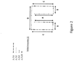
- FIG. 2 is a diagram depicting a folded resonator structure 22 of this invention.
- the resonator in one embodiment of the present invention is a 3/4 ⁇ metal structure bent, as shown in Figure 2 having a "folded" structure making for opposing electrodes between which an intense electric field is developed.
- Exemplary characteristics of the "folded structure" antenna are listed in the following table: Table 1 Wavelength (nm) Antenna Side 1400 1300 1200 1100 1000 900 800 700 600 500 400 A 175.0 162.5 150.0 137.5 125.0 112.5 100.0 87.5 75.0 62.5 50.0 B 65.6 60.9 56.3 52.6 46.9 42.2 37.5 32.8 28.1 23.4 18.8 C 196.9 182.8 168.8 154.7 140.6 126.6 112.5 98.4 84.4 78.3 56.3 D 218.8 203.1 187.5 171.9 156.3 140.6 125.0 109.4 33.8 78.2 62.5 Total 2093.8 1015.5 937.5 859.4 781.3 703.1 625.0 546.9 468.8 390.6 312.5 3/4 lambda 1050 975 900 825 750
- resonators shown in most of the drawings could be characterized as having a rectangular-shape loop connecting the opposing antenna sections or electrodes together, the invention is not so limited.
- Other "loop" shapes could be used, so long as the opposing electrodes are parallel and coplanar with one another, with the loop forming an electrical path having a length of 1 ⁇ 2 ⁇ , with the opposing electrodes having a length of 1/8 ⁇ each, thereby making the 3 ⁇ 4 ⁇ resonator.
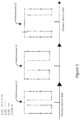
- Figure 3 is a diagram depicting the basic concepts underlying one of the energy augmentation structures of this invention.
- a sinusoidal wave representing for example an instantaneous waveform of a light wave (an incident energy flux 12).
- the depiction shows the length of 3 ⁇ 4 of the wavelength , and how in one embodiment a 3 ⁇ 4 resonator is constructed with the open ends of the resonator "folded" together to form in this embodiment a 3 ⁇ 4 folded resonator 22.
- the folded ends form a region of an intensified, amplified electric field denoted by the horizontally directed arrows between the opposing open ends.
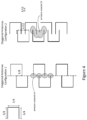
- a resonating antenna could have the configuration below shown in Figure 4 .
- the 3 ⁇ 4 structures oppose and are interdigitated together without a "folded" structure.
- the horizontal stubs are 3 ⁇ 4 long
- the vertical extending connectors are 1 ⁇ 4 long
- the vertical spacing between the horizontal stubs and the extend of interdigitation varies as shown between configuration 1 and configuration 2.
- an energy converter, a light or electron emitting material, or a color emitting or color converter material i.e., emissive material 24
- emissive material 24 is placed inside or around the region of an intensified electric field, as shown in Figure 4 .
- Figure 5 shows that different 3 ⁇ 4 folded resonators can be made having different distances between the opposing electrodes and thus different electric field strengths.
- the folded resonators of the invention can be adjusted such that the strength of the electric field between the opposing electrodes does not exceed the dielectric strength of any material in between.
- Exceeding the dielectric strength of any material in between could result in destruction of that material as intense current (e.g., a micro-arc) would flow during any time that the dielectric strength was exceeded, thus breaking the material down.
- the opposing sides need not have an exact length of 1/8 ⁇ .
- an energy converter, a light or electron emitting material, or a color emitting or color converter material (i.e., an emissive material) 24 is placed inside or around the regions of intensified electric field near/between the opposing electrodes.
- the color emitting or color converter material may itself be absorbing a color light such as for example blue light and emitting lower energy, down-shifted red light. In this case, a red phosphor could be the color emitting or color converter material.
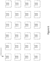
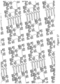
- Figure 6 is diagram showing a pattern of 3 ⁇ 4 folded resonators 22 distributed in space. As to be discussed in more detail later, there are numerous ways to distribute the 3 ⁇ 4 folded resonators. The present invention is not limited to the regular, uniformly spaced and sized resonators shown in Figure 6 . There is no requirement that the distribution be regular, uniformly spaced, uniformly sized, or uniformly oriented. Differently sized, spaced, and oriented resonators may provide better utilization of the full spectrum of the sun or any other light source incident on the object.
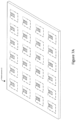
- Figure 7A is a diagram showing a pattern of 3 ⁇ 4 folded resonators 22 distributed in a plane or otherwise along a surface of an object.
- this pattern could be formed by lithographic or stamping processes onto a planar surface such as a glass plate or onto a curved sheet type product.
- the glass plate could itself be a phosphorescent plate or could have sections of different phosphorescent material deposited in a pattern that would align/match the respective positions of the opposing electrodes on each resonator.
- the sheet product could be a laminate type of product applied to for example a nominally white object.
- the infrared part of the solar spectrum normally only heating the surface
- the energy augmentators could be disposed on a perforated sheet, as shown in Figure 7B .
- the perforations in one embodiment are in the regions of intensified electric field such that phosphors or other energy converting materials or devices could be disposed in the perforations.
- the sheet product could be a laminate type of product applied to for example a nominally green object.
- the infrared part of the solar spectrum normally only heating the surface
- the intensified electric field regions In those regions, down converting phosphors converting blue, deep blue and ultraviolet light to green light would convert the blue, deep blue, and ultraviolet light of the solar spectrum to green light and the intensified electric field would enhance greater green light emission.
- the sheet product could be a laminate type of product applied to for example a nominally red object.
- the infrared part of the solar spectrum normally only heating the surface
- the intensified electric field regions In those regions, down converting phosphors converting green, blue, deep blue and ultraviolet light to red light would convert the green, blue, deep blue and ultraviolet light of the solar spectrum to red light and the intensified electric field would enhance greater red light emission.
- the energy augmentators could be disposed on a sheet and then separated into distinct pieces, as shown in Figure 7C , which could be readily added and mixed into a medium to be processed.
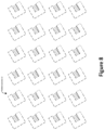
- Figure 8 is a diagram showing a pattern of 3 ⁇ 4 folded resonators 22 distributed in a plane or otherwise along a surface of an object and having a different orientation than in Figure 7 .
- the rotating polarized sun light waves which may at one instance not have an electric field alignment conducive to driving the 3 ⁇ 4 folded resonators, would have their electric field alignment conducive to driving resonators of a different orientation and therefore better aligned. Accordingly, if the sheet type products were used, layers of differently oriented 3 ⁇ 4 folded resonators could be stacked together.
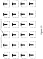
- Figure 9 is a diagram showing a pattern of 3 ⁇ 4 folded resonators 22 having an energy converter, a light or electron emitting material, or a color emitting or color converter material (i.e., emissive material 24) deposited in the region of between the opposing electrodes.
- the color converting or enhancing material deposited in the region of between the opposing electrodes may be deposited such that the color converting or enhancing material has an upper surface raised above the metal traces of the 3 ⁇ 4 folded resonators.
- the raised sections would intercept fringing fields of the intensified electric field between the opposing electrodes.
- Figure 10 is a diagram showing a pattern of 3 ⁇ 4 folded resonators 22 having an energy converter, a light or electron emitting material, or a color emitting or color converter material (i.e., emissive material 24) deposited in the region of between the opposing electrodes.
- the color converting or enhancing material deposited in the region of between the opposing electrodes may be deposited such that the color converting or enhancing material has an upper surface raised above the metal traces of the 3 ⁇ 4 folded resonators.
- the raised sections would intercept fringing fields of the intensified electric field between the opposing electrodes.
- the raised sections would extend around the corners where geometrically the corners would further intensify the electric field.
- Figure 11 is a diagram showing a pattern of 3 ⁇ 4 folded resonators 22 having an energy converter, a light or electron emitting material, or a color emitting or color converter material (i.e., emissive material 24) deposited in the region of between the opposing electrodes.
- the color converting or enhancing material deposited in the region of between the opposing electrodes may be deposited such that the color converting or enhancing material has an upper surface raised above the metal traces of the 3 ⁇ 4 folded resonators.
- the raised sections would intercept fringing fields of the intensified electric field between the opposing electrodes.
- the raised sections would extend around the corners where geometrically the corners would further intensify the electric field and would extend around the ends of the opposing electrodes.
- the energy converters, or light or electron emitting materials, or color emitting or color converter materials are disposed in a vicinity of one or more energy augmentation structures (i.e., the 3 ⁇ 4 folded resonators).
- the energy augmentation structures preferably are in a region of intensified electric field.
- the intensified electric field may represent a region of intensified energy especially if there is electrical current flow conductively coupling the energy converter to the one energy augmentation structures.
- conductively coupling the energy converter to the one energy augmentation structures has advantages.
- the energy converters or color converting or enhancing materials disposed in a vicinity of one or more energy augmentation structures may have a physical conductive connection between the energy converter and the at least one energy augmentation structure.
- the coupling may be more that of radiatively or capacitively coupling the electric fields from the resonant structure into energy converters or color converting or enhancing materials disposed inside the energy augmentation structure, outside the energy augmentation structure, in a layer with the energy augmentation structure, or in a layer above or below the energy augmentation structure.
- the color converting or enhancing materials are disposed in a vicinity of the energy augmentation structures
- Figure 12 is a diagram showing a pattern of 3 ⁇ 4 folded resonators 30 having for its metal traces a fractal pattern for the electrical path that loops around to connect the opposing electrodes.
- a fractal pattern for the electrical path with this pattern means that the metal trace can support various wavelengths resonating with the 3 ⁇ 4 characteristics because of the multiplicity of possible loop paths available because the widths of each segment of the conductive path vary in width permitting electrical paths of different physical lengths to exist around the loop.
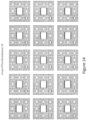
- Figure 13 is a diagram showing another fractal antenna segment 32 where the straight-line sides of the metal pads have regions 24 of locally intensified electric field.
- the fractal antenna segment is designed for resonance in the infrared range, with the intensifies electric field regions 34 (for example as shown toward the straight-line sides of the metal pads being the place where blue phosphors and red phosphors (or other emissive materials 24) would be deposited such that their emission, would be enhanced the intensified electric fields in those regions 34.
- Figure 14 is a diagram showing a repeated pattern (array) of the fractal antenna segments 32 of Figure 13 .
- Figure 15 is a diagram showing a pattern (array) of bowtie fractal antenna segments, providing an alternative embodiment to the fractal antenna segments of Figure 14 .
- the resonant structures can comprise three-dimensional fractal patterns.
- Known in the art is the fabrication of three-dimensional fractal structures by nanoscale anisotropic etching of silicon such as described in Nanoscale etching of 3d fractal structures with many applications including 3d fractal antennas and structures for filters, by Brian Wang, June 22, 2013, in the Journal of Micromechanics and Microengineering, (available at wvw.nextbigfuture.com/2013/06/nanoscale-etching-of-3d-fractal.html ).
- metal is deposited over a silicon three-dimensional fractal structure to form a multi-dimensional light collector.
- Figure 16 is a diagram showing a paired three-dimensional fractal structure with regions 34 of an intensified electric field in between the pairs.
- the paired three-dimensional fractal structure is a color enhancement structure according to one embodiment of the invention.
- these pyramidal type structures would be metallized with opposing faces metalized, a first loop conductor formed around the other sides of the first pyramid, then connecting across a region between the pair, and then a second loop formed around the sides of the second pyramid to the metallized opposing face of the second pyramid, to mimic (as seem from above) the 3 ⁇ 4 folded resonators shown in Figure 3 .
- converter (emissive) materials 24 would be disposed nearby different sections of the pyramidal type structures and preferably between the opposing faces of the pair where the intensified electric field (depicted by the arrows) exists.
- red, yellow, green, and blue converters or other designated emitters could be disposed at different levels within this region of intensified electric field.
- Figure 17 is a diagram showing a pattern (array) of the paired three-dimensional fractal structures of Figure 16 .
- the energy converters, or light or electron emitting materials, or color emitting or color converter materials are disposed in a vicinity of one or more energy augmentation structures (i.e., the 3 ⁇ 4 folded resonators).
- the energy augmentation structures preferably are in a region of intensified electric field.
- the intensified electric field may represent a region of intensified energy especially if there is electrical current flow conductively coupling the energy converter to the one energy augmentation structures.
- conductively coupling the energy converter to the one energy augmentation structures has advantages.
- the energy converters, or light or electron emitting materials, or color emitting or color converter materials disposed in a vicinity of one or more energy augmentation structures may have a physical conductive connection between the energy converter and the at least one energy augmentation structure.
- the coupling may be more that of radiatively coupling the electric fields from the resonant structure into energy converters or color converting or enhancing materials disposed inside the energy augmentation structure, outside the energy augmentation structure, in a layer with the energy augmentation structure, or in a layer above or below the energy augmentation structure.
- the energy augmentation structures are not limited to those shown above. Other variants are possible.
- the 3 ⁇ 4 folded resonators need not to have the "folded sections" which fold inwards as shown in Figure 3 .
- the 3 ⁇ 4 resonators of the invention can have folded sections which fold outward with the regions of intensified electric field being outside of the "loop" of the resonator. The distal ends of the antenna protrude outwardly while maintaining parallelism.
- Figure 8 is a schematic of a 3 ⁇ 4 external-electrode folded resonator 22. This external, opposed electrode pair design follows the general apportioning, scaling aspects, converter material placement, etc., shown in Figures 5 through 11 but with the internal folded sections being replaced by the external-electrode pair.
- the 3 ⁇ 4 external-electrode folded resonator 22 provides the capability to be packed in a concentric-type arrangement with progressively increasing or decreasing size resonators. These resonators are maintained in plane with no overlapping distal ends.
- Figure 19 is a schematic of a plurality of concentric-type 3 ⁇ 4 external-electrode folded resonators 22. Since each of the 3 ⁇ 4 external-electrode folded resonators 22 has a different electrical length, the plurality of concentric-type 3 ⁇ 4 external-electrode resonators will be "tuned" to the different wavelengths associated with the respective electrical lengths. Three different frequencies are therefore focused between the distal ends of the antennas.
- Figure 20 is a schematic of a plurality of concentric-type 3 ⁇ 4 external-electrode folded resonators 22 with overlapping electrodes.
- the overlapping provides a more concentrated/enhanced field region than in the non-overlapping arrangement of Figure 19 .
- the present invention is not limited to planar concentric type packing arrangements as shown in Figures 19 or 20 .
- the three different 3 ⁇ 4 wavelength resonators in Figure 20 are maintained in plane with overlapping distal ends. These antennas are inductively coupled.
- the present invention utilizes an off plane configuration with axial symmetry where the antennas are in an axially rotated, multiple frequency, interleaved 3 ⁇ 4 wave resonator structure.
- Figure 21 is a schematic of an axially rotated, multiple frequency, interleaved 3 ⁇ 4 wave resonators 22 showing (in this example) three differently sized resonators for multiple frequency resonance disposed about/along a common axis but axially rotated.
- the resultant electric field is concentrated without one electrode section perturbing the electric fields from another.
- an energy collector comprising at least one energy augmentation structure; and at least one energy converter capable of receiving an applied electromagnetic energy, converting the applied electromagnetic energy and emitting therefrom an emitted electromagnetic energy shifted in wavelength or energy from the applied electromagnetic energy and the energy converter being disposed in a vicinity of the at least one energy augmentation structure such that the emitted electromagnetic energy is emitted with at least one augmented property compared to if the energy converter were remote from the at least one energy augmentation structure.
- the present invention can use different levels for disposing 3 ⁇ 4 resonators thereon regardless of the resonators being 3 ⁇ 4 internally-folded resonators or 3 ⁇ 4 external-electrode resonators.
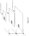
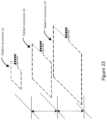
- This packing is shown in Figures 22 and 23 for configuration in parallel planes with distal ends folded in or protruding out respectively.
- the antennas are inductively decoupled.
- This configuration allows the electric field to be focused from three different frequencies in a longer path.
- This configuration can be used to create a mirror image configuration to extend the length of focused electric field as is illustrated in Fig. 24A .
- the resonator configuration in this case is mirror imaged with another set of antennas (folded resonators 22) to create a longer path (doubled) of focused electric field.
- the resonator antenna configuration can be placed in more creative ways to enhance the electric field focusing around a target as is illustrated in the Figure 24B .
- the configuration in Figure 25 allows the surrounding of a target within the plane of the resonator structure/antenna for the purpose of heating and focusing energy around the target. This prevents heat dissipation in silicon where the thermal conductivity is high.
- the silicon substrate in such an instance can be single crystalline, polycrystalline or amorphous.
- an "energy augmentation structure” represents a structure whereby a spatial region of the energy collector contains a converter material (or other light or electron emitting material) exposed to energy which stimulates emission of light at a different energy (wavelength) from that to which it is exposed while being in a spatial area/volume (e.g., between or around or in a vicinity of the folded structures or the external-electrode pairs) where there is an artificially induced higher electrical field and/or a higher energy density.
- These artificial regions can be produced for example by use of structures including, but not limited to, multiple level collection optics, resonators, fractal antennas, and electrical grid (or electrode) patterns.
- the energy augmentation structures of the invention are able to produce light which can be used for a variety of applications, in particular for photostimulation of biological, chemical, and physical reactions such as for example photoactivation of photoreactive drugs, photoactivation of photosensitive materials such as adhesives or lithographic photoresists, or for direct interaction with biological and chemical agents in the environment of the augmentation structures, as in sterilization.
- the light or electron emitting materials noted above are disposed with an energy augmentation structure comprising one or more of an electromagnetic resonator structure, a folded resonator structure, and a fractal resonating structure, any of which having a region of an intensified electromagnetic field within the resonating structures.
- the energy converter or light or electron emitting materials noted above includes one or more luminescing materials.
- luminescing materials there are uses of the energy augmentation structure and/or energy collector embodiments which enhance bioluminescence, chemo-luminescence, photoluminescence, fluorescence, mechano-luminescence, and/or electron emission.
- the energy converter or light emitting materials noted above includes for the one or more luminescent materials phosphorescent materials, fluorescent materials, electroluminescent materials, chemo-luminescent materials, bioluminescent materials, and mechano-luminescent materials used in conjunction with or not in conjunction with the energy augmentation structure noted above.
- the emitted electromagnetic energy from the luminescent material is emitted with at least one augmented property compared to if the energy converter (e.g., the luminescent material) were remote from the at least one energy augmentation structure.
- the bioluminescent materials are UV-emitting bioluminescent materials such as catalyzed luciferase and luminescent proteins.
- the energy converter or light emitting materials noted above includes for the one or more luminescing materials phosphorescent materials, fluorescent materials, electroluminescent materials, chemo-luminescent materials, bioluminescent materials, and mechano-luminescent materials used in conjunction with or not in conjunction with the energy augmentation structure noted above and which emit one of ultra-violet, visible, near infrared, and infrared light.
- the energy converter or light emitting materials includes for the one or more luminescing materials phosphorescent materials, fluorescent materials, electroluminescent materials, chemo-luminescent materials, bioluminescent materials, and mechano-luminescent materials used in conjunction with or not in conjunction with the energy augmentation structure noted above and which emit one of ultra-violet, visible, near infrared, and infrared light.
- UV-emitting electroluminescent materials or mechano-luminescent devices and materials can be used.
- UV-emitting bioluminescent materials can be used.
- metallic patterns form a folded resonator having opposing electrodes with electric fields directed in between, and a converter is positioned between the opposing electrodes or within fringing electric field of the opposing electrodes or otherwise in a vicinity of the opposing electrodes.
- the folded resonator is a 3 ⁇ 4 folded resonator.
- metallic patterns comprise at least one of Au, Ag, Cu, Al, or transparent metal oxides.
- the metallic patterns can be formed with refractory metals such for example Ti, W, and Mo.
- the metallic patterns referenced above comprise an external external-electrode pair structure having opposing electrodes with electric fields directed in between, and a converter is positioned between the opposing electrodes or within fringing electric field of the opposing electrodes or otherwise in a vicinity of the opposing electrodes.
- the resonator is a 3 ⁇ 4 external-electrode pair resonator.
- metallic patterns comprise at least one of Au, Ag, Cu, Al, or transparent metal oxides.
- the metallic patterns can be formed with refractory metals such for example Ti, W, and Mo.
- plural resonators and plural converters are disposed at multiple positions throughout a light collector.
- the plural converters are positioned to convert light being internally scattered within the light collector.
- a first level of metallic patterns (or a second level of metallic patterns) comprises a metal core cladded with a high-K dielectric and a subsequent cladding of a low-K dielectric.
- the first level of metallic patterns noted above (or the second level of metallic patterns) comprises a radial pattern of conductors.
- the first level of metallic patterns noted above (or the second level of metallic patterns) comprises a fractal pattern. In one example, the fractal pattern is embedded within a dielectric material.
- the first level of metallic patterns noted above comprises a three-dimensional fractal structure.
- a panel with the first level of metallic patterns and the second level of metallic patterns and optionally multiple converters formed therein or thereon.
- a sheet with the first level of metallic patterns and the second level of metallic patterns and optionally multiple converters formed therein or thereon.
- the first level of metallic patterns noted above is of different sizes and/or orientations to each other of the first level of metallic patterns or with respect to the second level of metallic patterns.
- the energy augmentator can collect or distribute light.
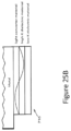
- Figure 25A is a schematic illustrating a distributed point light collector/transmitter of the invention showing a distribution of branches that can either collect light from distributed points 710 or conversely can distribute light from a central source 766 to the distributed points 710.
- the section of the collector/transmitter is shown in Figure 25B showing a core metal, an optional light converter material, a high K dielectric, and a low K dielectric. In this arrangement, as shown, light is confined and not loss to scatter out of the collector/transmitter, except at the ends.
- energy converters are used with the energy augmentators described above.
- the converters are for up conversion of light e.g., from the IR regime into visible electromagnetic radiation and for down conversion of light e.g., from the UV range into visible electromagnetic radiation.
- the invention in various embodiments up converts energy, preferably light in the visible spectrum.
- the invention encompasses a variety of applications where the up and down conversion materials with or without the energy augmentators are included to enhance electromagnetic energy emission, preferably light or photon emission.
- An energy augmentator may be separate from or connected to the energy converter.
- the energy converter can have the energy augmentator formed on its surface through chemical vapor deposition ("CVD") or physical vapor deposition (“PVD”) processes or other nanoscale “printing” methods.
- CVD chemical vapor deposition
- PVD physical vapor deposition
- Such embodiments may be particularly useful in methods for treating human or animal patients, in which having such energy augmentators "imprinted” on a surface of the energy converter can guarantee proximity between the energy augmentator and the energy converter to maximize the interaction with the energy being applied.
- the energy augmentator can be formed on a surface of an inert non-energy converting particle, formed, for example, from silica or formed from a non-energy converting particle coated with an biologically and/or chemically inert coating (such as, for example, diamond, diamond-like carbon, or similar inert materials). Such an energy augmentator can then be co-administered with the energy converter to the human or animal patient.
- Suitable energy modulation agents or energy converters include, but are not limited to, a biocompatible fluorescing metal nanoparticle, fluorescing dye molecule, gold nanoparticle, a water soluble quantum dot encapsulated by polyamidoamine dendrimers, a luciferase (bioluminescence), a biocompatible phosphorescent molecule, a combined electromagnetic energy harvester molecule, and a lanthanide chelate capable of intense luminescence.
- the energy modulation agent or energy converter can emit energy in a form suitable for absorption at a target site or receptor.
- the initiation energy source may be acoustic energy and one energy converter may be capable of receiving acoustic energy and emitting photonic energy (e.g. sonoluminescent molecules) to be received by another energy converter that is capable of receiving photonic energy.
- photonic energy e.g. sonoluminescent molecules
- Other examples include energy converters that receive energy at x-ray wavelength and emit energy at UV wavelength, preferably at UV-A wavelength. A plurality of such energy converters may be used to form a cascade to transfer energy from initiation energy source via a series of energy converters.
- Resonance Energy Transfer is an energy transfer mechanism between two molecules having overlapping emission and absorption bands. Electromagnetic emitters are capable of converting an arriving wavelength to a longer wavelength. For example, UV-B energy absorbed by a first molecule may be transferred by a dipole-dipole interaction to a UV-A-emitting molecule in close proximity to the UV-B-absorbing molecule. Alternatively, a material absorbing a shorter wavelength may be chosen to provide RET to a non-emitting molecule that has an overlapping absorption band with the transferring molecule's emission band. Alternatively, phosphorescence, chemiluminescence, or bioluminescence may be used to transfer energy to a target site or a receptor such as a photoactivatable agent.
- a biocompatible emitting source such as a fluorescing metal nanoparticle or fluorescing dye molecule, is selected as an energy converter that emits in the UV-A band.
- an energy converter comprising a UV-A emitting source can be a gold nanoparticle comprising for example a cluster of 5 gold atoms.
- an energy converter comprising a UV- or light-emitting luciferase is selected as the emitting source.
- a luciferase may be combined with ATP or another molecule, which may then be oxygenated with additional molecules to stimulate light emission at a desired wavelength.
- a phosphorescent emitting source may be used as the energy converter.
- One advantage of a phosphorescent emitting source is that the phosphorescent emitting molecules or other source may be electroactivated or photoactivated prior to insertion into the tumor either by systemic administration or direct insertion into the region of the tumor.
- Phosphorescent materials may have longer relaxation times than fluorescent materials, because relaxation of a triplet state is subject to forbidden energy state transitions, storing the energy in the excited triplet state with only a limited number of quantum mechanical energy transfer processes available for returning to the lower energy state. Energy emission is delayed or prolonged from a fraction of a second to several hours. Otherwise, the energy emitted during phosphorescent relaxation is not otherwise different than fluorescence, and the range of wavelengths may be selected by choosing a particular phosphor.
- the energy converters of the invention can include persistent after-glow phosphor materials emitting light in the visible to near ultraviolet and ultraviolet range.
- Eu-doped strontium aluminate is used as an energy converter in which deep UV light or x-ray or electron beans "charge" the photoluminescence such that these phosphors can be charged outside for example a patient and then injected into target or diseased site where UV photons would be emitted.
- gadolinium strontium magnesium aluminate is used as an energy converter in which deep UV light or x-ray or electron beans "charge" the photoluminescence such that these phosphors can be charged outside for example a patient and then injected into target or diseased site where UV photons would be emitted.
- U.S. Pat. Appl. Publ. No. 20070221883 describes specifically gadolinium-activated strontium magnesium aluminate having an excitation maximum at about 172 nm, and which emits in a narrow-band UV emission at about 310 nm.
- the '883 publication also describes other useful energy converters for this invention, making note of emission spectra between 300 nm and 320 nm for a Sr(Al,Mg) 12 O 19 :Gd phosphor and two 312 nm line emitting phosphors, YMgB 5 O 10 :Gd, Ce and YMgB 5 O 10 :Gd, Ce, Pr.
- WO2016200349 describes long lasting yellowish-green emitting phosphorescent pigments in the strontium aluminate (SrAl2O4) system, which could serve as energy converters in the present invention.
- WO 2016200348 describes long lasting bluish-green emitting phosphorescent pigments in the strontium aluminate (Sr4Al14O25) system, which could serve as energy converters in the present invention.
- the phosphor described by Xiong et al as CaAl 2 O 4 :Ce 3+ having an emission peak of 400 nm and a persistent time of more than 10 h could be used, where it would be charged by x-ray irradiation outside a patient and then injected at a diseased site to provide internally generated UV light.
- the persistent phosphors noted could be activated ex vivo and introduced along with psoralen (or other photoactivatable drug) into the patient by exchange of a bodily fluid or for example by supplying the persistent phosphors and the photoactivatable drug into a patient's blood stream.
- the persistent phosphors noted could be activated in vivo by injection of the phosphors into a diseased site and then exposure to x-rays.
- a combined electromagnetic energy harvester molecule is designed, such as the combined light harvester disclosed in J. Am. Chem. Soc. 2005, 127, 9760-9768 .
- a resonance energy transfer cascade may be used to harvest a wide band of electromagnetic radiation resulting in emission of a narrow band of fluorescent energy.
- a Stokes shift of an emitting source or a series of emitting sources arranged in a cascade is selected to convert a shorter wavelength energy, such as X-rays, to a longer wavelength fluorescence emission such an optical or UV-A.
- a lanthanide chelate capable of intense luminescence is used as an energy converter.
- a biocompatible, endogenous fluorophore emitter is selected as an energy converter.
- the energy converters of the invention can include visible and UV-light emitting bioluminescent materials.
- bioluminescent materials such as coelenterate-type luciferin analogues could be used including amide monoanion known to emit at 480 nm and oxyluciferin known to emit at 395 nm.
- nanoparticle refers to a particle having a size less than one micron. While the description of the invention describes specific examples using nanoparticles, the invention in many embodiments is not limited to particles having a size less than one micron. However, in many of the embodiments, the size range of less than one micron, and especially less than 100 nm produces properties of special interest such as for example emission lifetime luminescence quenching, luminescent quantum efficiency, and concentration quenching and such as for example diffusion, penetration, and dispersion into mediums where larger size particles would not migrate.
- This invention in various embodiments can use a wide variety of down conversion materials (or mixtures of down conversion materials) with or without the energy augmentators to enhance light or photon emission.
- These down conversion materials can include quantum dots, semiconductor materials, alloys of semiconductor materials, scintillation and phosphor materials, materials that exhibit X-ray excited luminescence (XEOL), organic solids, metal complexes, inorganic solids, crystals, rare earth materials (lanthanides), polymers, scintillators, phosphor materials, etc., and materials that exhibit excitonic properties.
- the down conversion materials to enhance light or photon emission can convert energy from one of ultraviolet light, x-rays, and high energy particles to visible light.
- the down conversion materials to enhance light or photon emission can convert energy from higher energy visible light to lower energy visible light.
- a quantum dot mixture with or without the energy augmentators can be used for the multiple nanoparticles.
- Quantum dots are in general nanometer size particles whose energy states in the material of the quantum dot are dependent on the size of the quantum dot.
- quantum dots are known to be semiconductors whose conducting characteristics are closely related to the size and shape of the individual crystal. Generally, the smaller the size of the crystal, the larger the band gap, the greater the difference in energy between the highest valence band and the lowest conduction band becomes. Therefore, more energy is needed to excite the dot, and concurrently, more energy is released when the crystal returns to its resting state.
- Quantum dots represent one way to down convert ultraviolet light of the spectrum to a targeted wavelength or energy emission. Quantum dots represent one way to down convert blue light of the spectrum to a targeted wavelength or energy emission.
- quantum dots can comprise various materials including semiconductors such as zinc selenide (ZnSe), cadmium selenide (CdSe), cadmium sulfide (CdS), indium arsenide (InAs), and indium phosphide (InP).
- semiconductors such as zinc selenide (ZnSe), cadmium selenide (CdSe), cadmium sulfide (CdS), indium arsenide (InAs), and indium phosphide (InP).
- ZnSe zinc selenide
- CdSe cadmium selenide
- CdS cadmium sulfide
- InAs indium arsenide
- InP indium phosphide
- TiO 2 titanium dioxide
- the size of the particle, i.e., the quantum dot 18, may range from about 2 to 10 nm. Since the size of these particles is so small, quantum physics governs many of the electrical and optical
- quantum dots absorb a broad spectrum of optical wavelengths and re-emit radiation having a wavelength that is longer than the wavelength of the absorbed light.
- the wavelength of the emitted light is governed by the size of the quantum dot.
- CdSe quantum dots 5.0 nm in diameter emit radiation having a narrow spectral distribution centered about 625 nm while quantum dots 18 including CdSe 2.2 nm in size emit light having a center wavelength of about 500 nm.
- Semiconductor quantum dots comprising CdSe, InP, and InAs, can emit radiation having center wavelengths in the range between 400 nm to about 1.5 ⁇ m. Titanium dioxide TiO 2 also emits in this range.
- the linewidth of the emission i.e., full-width half-maximum (FWHM)
- FWHM full-width half-maximum
- quantum dots simply need to absorb light having wavelengths shorter than the wavelength of the light emitted by the dots. For example, for 5.0 nm diameter CdSe quantum dots light having wavelengths shorter than about 625 nm is absorbed to produce emission at about 625 nm while for 2.2 nm quantum dots comprising CdSe light having wavelengths smaller than about 500 nm is absorbed and re-emitted at about 500 nm. In practice, however, the excitation or pump radiation is at least about 50 nanometers shorter than the emitted radiation.
- a quantum dot mixture (QDM) coating can be deposited using CVD and or sol-gel techniques using standard precipitation techniques.
- the QDM coating can be made of a silicate structure that does not diminish UV output. Within the silicate family, silica (SiO 2 ) is suitable since it maximizes UV transmission through the coating.
- the coating can further include a second layer of a biocompatible glass.
- bio-compatible glass and glass ceramic compositions can contain calcium, a lanthanide or yttrium, silicon, phosphorus and oxygen.
- Other biocompatible materials and techniques are described in the following patents : U.S. Pat. Nos.
- the down conversion materials for the invention described here can be coated with insulator materials such as for example silica which will reduce the likelihood of any chemical interaction between the luminescent particles and the medium the particles are included therein.
- insulator materials such as for example silica which will reduce the likelihood of any chemical interaction between the luminescent particles and the medium the particles are included therein.
- These and the other conversion materials described here can be used with or without energy augmentators.
- energy augmentators For biocompatible applications of inorganic nanoparticles, one of the major limiting factors is their toxicity. Generally speaking, all semiconductor nanoparticles are more or less toxic. For biocompatible applications, nanoparticles with toxicity as low as possible are desirable or else the nanoparticles have to remain separated from the medium. Pure TiO 2 , ZnO, and Fe 2 O 3 are biocompatible.
- CdTe and CdSe are toxic, while ZnS, CaS, BaS, SrS and Y 2 O 3 are less toxic.
- the toxicity of nanoparticles can result from their inorganic stabilizers, such as TGA, or from dopants such as Eu 2+ , Cr 3+ or Nd 3+ .
- Other suitable down conversion materials which would seem the most biocompatible are zinc sulfide, ZnS:Mn 2+ , ferric oxide, titanium oxide, zinc oxide, zinc oxide containing small amounts of Al 2 O 3 , and AgI nanoclusters encapsulated in zeolite.
- lanthanum and gadolinium oxyhalides activated with thulium
- Er 3+ doped BaTiO 3 nanoparticles Er 3+ doped BaTiO 3 nanoparticles
- Yb 3+ doped CsMnCl 3 and RbMnCl 3 BaFBr:Eu 2+ nanoparticles
- Cesium Iodine Bismuth Germanate, Cadmium Tungstate, and CsBr doped with divalent Eu.
- the following luminescent polymers with or without energy augmentators are also suitable as conversion materials: poly(phenylene ethynylene), poly(phenylene vinylene), poly(p-phenylene), poly(thiophene), poly(pyridyl vinylene), poly(pyrrole), poly(acetylene), poly(vinyl carbazole), poly(fluorenes), and the like, as well as copolymers and/or derivatives thereof.
- the following materials with or without energy augmentators can be used similar to that detailed in U.S. Pat. No. 7,090,355 .
- the following materials can be used.
- Inorganic or ceramic phosphors or nano-particles including but not limited to metal oxides, metal halides, metal chalcogenides (e.g. metal sulfides), or their hybrids, such as metal oxo-halides, metal oxo-chalcogenides.
- Organometallic molecules including at least a metal center such as rare earth elements (e.g. Eu, Tb, Ce, Er, Tm, Pr, Ho) and transitional metal elements such as Cr, Mn, Zn, Ir, Ru, V, and main group elements such as B, Al, Ga, etc.
- the metal elements are chemically bonded to organic groups to prevent the quenching of the fluorescence from the hosts or solvents.
- Phosphors can be used including the Garnet series of phosphors: (Y m A 1-m ) 3 (Al n B 1-n ) 5 O 12 , doped with Ce; where 0 ⁇ m, n ⁇ 1, where A includes other rare earth elements, B includes B, Ga.
- phosphors containing metal silicates, metal borates, metal phosphates, and metal aluminates hosts can be used.
- nano-particulates phosphors containing common rare earth elements (e.g. Eu, Tb, Ce, Dy, Er, Pr, and Tm) and transitional or main group elements (e.g. Mn, Cr, Ti, Ag, Cu, Zn, Bi, Pb, Sn, and Tl) as the fluorescent activators can be used.
- Materials such as Ca, Zn, Cd in tungstates, metal vanadates, ZnO, etc. can be used.
- the commercial laser dye materials obtained from several laser dye vendors can also be used with or without energy augmentators.
- a partial list of the preferred laser dye classes includes: Pyrromethene, Coumarin, Rhodamine, Fluorescein, other aromatic hydrocarbons and their derivatives, etc..
- polymers containing unsaturated carbon-carbon bonds which also serve as fluorescent materials and find many optical and fluorescent applications.
- MEH-PPV, PPV, etc. have been used in opto-electronic devices, such as polymer light emitting diodes (PLED).
- PLED polymer light emitting diodes
- semiconductor nanoparticles can be used with or without energy augmentators.
- semiconductor nanoparticles in the art refers to an inorganic crystallite between 1 nm and 1000 nm in diameter, preferably between 2 nm to 50 nm.
- a semiconductor nano-particle is capable of emitting electromagnetic radiation upon excitation (i.e., the semiconductor nano-particle is luminescent).
- the nanoparticle can be either a homogeneous nano-crystal, or comprises of multiple shells.
- the nanoparticle can include a "core" of one or more first semiconductor materials, and may be surrounded by a "shell" of a second semiconductor material.
- the core and/or the shell can be a semiconductor material including, but not limited to, those of the group II-VI (ZnS, ZnSe, ZnTe, CdS, CdSe, CdTe, HgS, HgSe, HgTe, MgS, MgSe, MgTe, CaS, CaSe, CaTe, SrS, SrSe, SrTe, BaS, BaSe, BaTe, and the like) and III-V (GaN, GaP, GaAs, GaSb, InN, InP, InAs, InSb, and the like) and IV (Ge, Si, and the like) materials, and an alloy or a mixture thereof.
- group II-VI ZnS, ZnSe, ZnTe, CdS, CdSe, CdTe, HgS, HgSe, HgTe, MgS, MgSe, MgTe, CaS, CaSe,
- Fluorescent organometallic molecules containing rare earth or transitional element cations can be used for down conversion materials with or without energy augmentators.
- Such molecules include a metal center of rare earth elements including Eu, Tb, Er, Tm, Ce protected with organic chelating groups.
- the metal center may also include transitional elements such as Zn, Mn, Cr, Ir, etc. and main group elements such as B, Al, Ga.
- Such organometallic molecules can readily dissolve in liquid or transparent solid host media.
- Some examples of such fluorescent organometallic molecules include: 1. 'I'ris(dibenzoylmethane)mono(phenanthroline)europium(III), 2. Tris(8-hydroxyquinoline)erbium; 3.
- down-conversion materials for red emission include those discussed above and europium complexes such as those described in JP Laid-open Patent Publication (Kokai) No. 2003-26969 , constructed such that ⁇ -diketone ligand is coordinated to europium forming an europium complex capable of emitting red fluorescence.
- Other specific examples of the rare earth element complexes include complexes include lanthanum (Ln), europium (Eu), terbium (Tb), and gadolinium (Gd) and combinations thereof.
- An europium (Eu) complex is capable of emitting red fluorescence when irradiated with ultraviolet rays having a wavelength ranging from 365 nm to 410 nm.
- Terbium (Tb) is capable of emitting green fluorescence when irradiated with ultraviolet rays having a wavelength of 365 nm.
- the down conversion materials which emit red light may include europium, light emitting particles which emit green light may include Terbium, and light emitting particles which emit blue or yellow light may include cerium (and/or thulium).
- up conversion materials which emit red light may include praseodymium, light emitting particles which emit green light may include erbium, and light emitting particles which emit blue light may include thulium.
- the conversion materials can be light emitting particles made of fluorescent molecules that emit different colors (e.g. red, green, and blue), or different wavelengths or energies of light.
- the conversion materials can be light emitting particles made of pure organic or organo-metallic dyes with or without energy augmentators.
- rare earth complexes such as a combination of a europium complex and a terbium complex
- down converter materials include for example ZnS, PbS, SbS 3 , MoS 2 , PbTe, PbSe, BeO, MgO. Li 2 CO 3 , Ca(OH) 2 , MoO 3 , SiO 2 , Al 2 O 3 , TeO 2 , SnO 2 , KBr, KCl, and NaCl. These materials can include dopants to tailor the emission properties, as noted above.
- Examples of doped (or alloyed) glass systems suitable for the include Y 2 O 3 :Gd, Y 2 O 3 :Dy, Y 2 O 3 :Tb, Y 2 O 3 :Ho, Y 2 O 3 :Er, Y 2 O 3 :Tm, Gd 2 O 3 :Eu, Y 2 O 2 S:Pr, Y 2 O 2 S:Sm, Y 2 O 2 S:Eu, Y 2 O 2 S:Tb, Y 2 O 2 S:Ho, Y 2 O 2 S:Er, Y 2 O 2 S:Dy, Y 2 O 2 S:Tm, ZnS:Ag:Cl (blue), ZnS:Cu:Al (green), Y 2 O 2 S:Eu (red), Y 2 O 3 :Eu (red), YVO 4 :Eu (red), and Zn 2 SiO 4 :Mn (green).
- U.S. Pat. No. 4,705,952 describes an infrared-triggered phosphor that stores energy in the form of visible light of a first wavelength and released energy in the form of visible light of a second wavelength when triggered by infrared light.
- the phosphors in U.S. Pat. No. 4,705,952 were compositions of alkaline earth metal sulfides, rare earth dopants, and fusible salts.
- 4,705,952 were more specifically phosphors made from strontium sulfide, barium sulfide and mixtures thereof; including a dopant from the rare earth series and europium oxide, and mixtures thereof; and including a fusible salt of fluorides, chlorides, bromides, and iodides of lithium, sodium, potassium, cesium, magnesium, calcium, strontium, and barium, and mixtures thereof.
- the materials described in U.S. Pat. No. 4,705,952 are useful in various embodiments of the invention with or without energy augmentators.
- the infrared-triggered phosphors would be used in conjunction with the folded resonators, and the receipt of a microwave or IR signal would locally heat and trigger emission. (This application would be particularly well suited for color enhancement and/or security applications.)
- the down converter materials can include Y 2 O 3 : Li.
- Sun et al Luminescent properties of Li+ doped nanosized Y2O3:Eu
- Solid State Comm. 119 (2001) 393-396 describe such materials.
- Hou et al Luminescent properties nano-sized Y2O3:Eu fabricated by co-precipitation method
- Journal of Alloys and Compounds, vol. 494, issue 1-2, 2 April 2010, pages 382-385 describe that nano-sized yttria (Y 2 O 3 ) powders have been successfully synthesized by a co-precipitation method.
- Specific downconverting materials may also include at least one or more of Y 2 O 3 , Y 2 O 3 :Gd, Y 2 O 2 S, NaYF 4 , NaYbF 4 , YAG, YAP, Nd 2 O 3 , LaF 3 , LaCl 3 , La 2 O 3 , TiO 2 , LuPO 4 , YVO 4 , YbF 3 , YF 3 , Na-doped YbF 3 , ZnS, ZnSe, MgS, CaS, Zn 2 SiO 4 :Mn, LaOBr:Tm and alkali lead silicate including compositions of SiO 2 , B 2 O 3 , Na 2 O, K 2 O, PbO, MgO, or Ag, and combinations or alloys or layers thereof.
- the down-converting materials can be sulfur containing phosphors, which can help for example in the rubber vulcanization or other photoactivated processes.
- An example of such a sulfur containing phosphor is: (Sr,Ca)Ga 2 S 4 .
- said phosphor particles comprise a thiogallate host material selected from the group consisting of SrGa 2 S 4 , CaGa 2 S 4 BaGa 2 S 4 , MgGa 2 S 4 and solid solutions thereof.
- the particle size of such phosphor can be controlled from 25 nm to 300 microns in size as described in US6153123A .
- the downconverting materials can include a dopant including at least one of Er, Eu, Yb, Tm, Nd, Mn, Sb, Tb, Ce, Y, U, Pr, La, Gd and other rare-earth species or a combination thereof.
- the dopant can be included at a concentration of 0.01%-50% by mol concentration. At times it is preferable to have a combination of dopants rather than one dopant such is the case for a Mn and Sb in silicate matrices.
- the invention in other embodiments can use a wide variety of up conversion materials (or mixtures of up converters) with or without the energy augmentators to enhance a particular wavelength or energy of light emitted from a material or surface.
- up conversion materials can include similar materials as discussed above with regard to down conversion but typically included doped or impurity states in a host crystal that provide a mechanism for up conversion pumping.
- the up conversion materials to enhance wavelength or energy emission can convert energy from one of near infrared, infrared, and microwave irradiation.
- the upconversion materials to enhance color emission can convert energy from lower energy visible light to higher energy visible light.
- a nanoparticle of a lanthanide doped oxide can be excited with near infrared light such as laser light at 980 nm and 808 nm to produce visible light in different parts of the red, green, blue spectrum (different wavelengths or energies) depending on the dopant trivalent rare earth ion(s) chosen, their concentration, and the host lattice.
- near infrared light such as laser light at 980 nm and 808 nm to produce visible light in different parts of the red, green, blue spectrum (different wavelengths or energies) depending on the dopant trivalent rare earth ion(s) chosen, their concentration, and the host lattice.
- the lanthanide doped oxides suitable for this invention differ from more traditional multi-photon up conversion processes where the absorption of, for example, two photons is needed in a simultaneous event to promote an electron from a valence state directly into an upper level conduction band state where relaxation across the band gap of the material produces fluorescence.
- the co-doping produces states in the band gap of the NaYF 4 such that the Yb 3+ ion has an energy state at 2 F 5/2 pumpable by a single photon event and from which other single photon absorption events can populate even higher states. Once in this exited state, transitions to higher energy radiative states are possible, from which light emission will be at a higher energy than that of the incident light pumping the 2 F 5/2 energy state.
- the energy state at 2 F 3/2 of the Yb 3+ ion is the state that absorbs 980 nm light permitting a population build up serving as the basis for the transitions to the higher energy states such as the 4 F 7/2 energy state.
- transitions from the 4 F 7/2 energy state produce visible emissions.
- U.S. Pat. No. 7,008,559 describes the upconversion performance of ZnS where excitation at 767 nm produces emission in the visible range.
- the materials described in U.S. Pat. No. 7,008,559 are suitable in various embodiments of the invention with or without the energy augmentators.
- materials specified for up conversion materials in the invention include CdTe, CdSe, ZnO, CdS, Y 2 O 3 , MgS, CaS, SrS and BaS.
- Such up conversion materials may be any semiconductor and more specifically, but not by way of limitation, sulfide, telluride, selenide, and oxide semiconductors and their nanoparticles, such as Zn 1-x Mn x S y , Zn 1-x Mn x Se y , Zn 1-x Mn x Te y , Cd 1-x MnS y .
- Some nanoparticles such as ZnS:Tb 3+ , Er 3+ ; ZnS:Tb 3+ ; Y 2 O 3 :Tb3 + ; Y 2 O 3 :Tb 3+ , Er3 + ; ZnS:Mn 2+ ; ZnS:Mn,Er 3+ are known in the art to function for both down-conversion luminescence and upconversion luminescence and would be suitable for the invention with or without energy augmentators.
- light emitting particles which emit red light may include praseodymium
- light emitting particles which emit green light may include erbium
- light emitting particles which emit blue light may include thulium.
- the upconversion process generally requires one of more rare-earth dopants, such as Er, Eu, Yb, Tm, Nd, Tb, Ce, Y, U, Pr, La, Gd and other rare-earth species or a combination thereof, doped into a dielectric crystal (of any size >0.1nm), including at least one of Y 2 O 3 , Y 2 O 2 S, NaYF 4 , NaYbF 4 , YAG, YAP, Nd 2 O 3 , LaF 3 , LaCl 3 , La 2 O 3 , TiO 2 , LuPO 4 , YVO 4 , YbF 3 , YF 3 , Na-doped YbF 3 , or SiO 2 , where incident radiation is at longer wavelength than emissive radiation from the crystal.
- rare-earth dopants such as Er, Eu, Yb, Tm, Nd, Tb, Ce, Y, U, Pr, La, Gd and other rare-e
- the dopant ion(s) chosen and their associated and relative concentration in the host crystal For the example of upconversion in a Y 2 O 3 host crystal, to achieve a blue emission ( ⁇ 450 - 480 nm) one could synthesize [Y 2 O 3 ; Yb (3%), Tm (0.2%)], where the Yb and Tm are the percentages doped in the crystal relative to the Y atoms being 100%.
- typical green upconversion materials are [Y 2 O 3 ; Yb (5%), Ho (1%)] and [Y 2 O 3 ; Yb (2%), Er (1%)]
- typical red upconversion materials are [Y 2 O 3 ; Yb (10%), Er (1%)] and [Y 2 O 3 ; Yb (5%), Eu (1%)].
- concentrations of dopants relative to each other and the crystal matrix must be tuned for every combination, and there are multiple ways to achieve multiple wavelength or energy emissions from even the same dopants.
- Up-conversion of red light with a wavelength of about 650 nm in Tm 3+ doped flourozirconate glasses can be used in the invention to produce blue light.
- the blue light consists of two emission bands; one at 450 nm which is ascribed to the 1D2 ⁇ 3H4 transition, the others at 475 nm is ascribed to the 1G4 ⁇ 3H6 transition.
- the emission intensities of both bands have been observed by others to vary quadratically with the excitation power.
- cross-relaxation processes occur which decrease the up-conversion efficiency.
- NIR near-infrared
- Tellurium and germanium oxides are also suitable upconverters. These glasses can be doped with Tm, Yb, Ho, Er, Pr, for example.
- Yb 3+ doped BaZrO 3 is also suitable for upconversion. Er 3+ and/or Tm 3+ doping are also suitable for tailoring the emission wavelengths.
- Nd 3+ :Cs 2 NaGdCl 6 and Nd 3+ , Yb 3+ :Cs 2 NaCdCl 6 polycrystalline powder samples prepared by Morss method have been reported to be up converters and are suitable for the present invention. These materials, under 785 nm irradiation, have shown upconversion emissions near 538 nm (Green), 603 nm (Orange), and 675 nm (Red) were observed and assigned to 4G7/2 ⁇ 419/2, (4G7/2 ⁇ 4I11/2; 4G5/2 ⁇ 4I9/2), and (4G7/2 ⁇ 4I13/2; 4G5/2 ⁇ 4I11/2), respectively.
- Nd 3+ and Ho 3+ co-doped -based ZrF 4 fluoride glasses under 800 nm excitation have been reported to be up converters and are suitable for the present invention.
- the green emission was seen to be extremely strong and the blue and red emission intensities were very weak.
- DPA 9,10-diphenylanthracene
- further energy converters include, but are not limited to, (not ranked by order of preference or utility): CaF 2 , ZnF 2 , KMgF 3 , ZnGa 2 O 4 , ZnAl 2 O 4 , Zn 2 SiO 4 , Zn 2 GeO 4 , Ca 3 (PO 4 ) 3 F, Sr 3 (PO 4 ) 3 F, CaSiO 3 , MgSiO 3 , ZnS, MgGa 2 O 4 , LaAl 11 O 18 , Zn 2 SiO 4 , Ca 5 (PO 4 ) 3 F, Mg 4 Ta 2 O 9 , CaF 2 , LiAl 5 O 8 , LiAlO 2 , CaPO 3 , AlF 3 , and LuPO 4 :Pr 3+
- Examples further include the alkali earth chalcogenide phosphors which are in turn exemplified by the following non-inclusive list: MgS:Eu 3+ , CaS:Mn
- ZnS type phosphors that encompass various derivatives: ZnS:Cu,Al(Cl), ZnS:Cl(Al), ZnS:Cu, I(Cl), ZnS:Cu, ZnS:Cu,In.
- the compound IIIb-Vb phosphors which include the group IIIb and Vb elements of the periodic table.
- These semiconductors include BN, BP, BSb, AlN, AlP, AlAs, AlSb, GaN, GaP, GaAs, GaSb, InN, InP, InAs, InSb and these materials may include donors and acceptors that work together to induce light emission diodes.
- donors include, but are not limited to, Li, Sn, Si, Li, Te, Se, S, O and acceptors include, but are not limited to, C, Be, Mg, Zn, Cd, Si, Ge.
- the major GaP light emitting diodes which include, but are not limited to, GaP:Zn,O, GaP:NN, Gap:N and GaP, which emit colors Red, Yellow, Green and Pure Green respectively.
- the materials can further include such materials as GaAs with compositional variation of the following sort: In 1-y (Ga 1-x Al x ) y P.
- silicon carbide SiC which has commercial relevancy as a luminescent platform in blue light emitting diodes. These include the polytypes 3C-SiC, 6H-SiC, 4H-SiC with donors such as N and Al and acceptors such as Ga and B.
- Another grouping by host compound includes chemical compositions in the halophosphates phosphors, phosphate phosphors, silicate phosphors, aluminate phosphors, borate phosphors, tungstate phosphors, and other phosphors.
- the halophosphates include, but are not limited to: 3Ca 3 (PO 4 ) 2 .Ca(F,Cl) 2 :Sb 3+ , 3Ca 3 (PO 4 ) 2 .Ca(F,Cl) 2 : Sb 3+ /Mn 2+ Sr 10 (PO 4 ) 6 Cl 2 :Eu 2+ , (Sr,Ca) 10 (PO 4 ) s Cl 2 :Eu 2+ , (Sr,Ca) 10 (PO 4 ) 6 .nB 2 O 3 :Eu 3+ , (Sr, Ca,Mg) 10 (PO 4 ) 6 Cl 2 :Eu 2+ .
- the phosphate phosphors include, but are not limited to: Sr 2 P 2 O 7 :Sn 2+ , (Sr,Mg) 3 (PO 4 ) 2 :Sn 2+ , Ca 3 (PO 4 ) 2 .Sn 2+ , Ca 3 (PO 4 ) 2 :Tl + , (Ca,Zn) 3 (PO 4 ) 2 :Tl + , Sr 2 P 2 O 7 :Eu 2+ , SrMgP 2 O 7 :Eu 2+ , Sr 3 (PO 4 ) 2 :Eu 2+ , LaPO 4 :Ce 3+ , Tb 3+ , La 2 O 3 .0.2SiO 2 .0.9P 2 O 5 :Ce 3+ .Tb 3+ , BaO.TiO 2 .P 2 O 5 .
- the aluminate phosphors include, but are not limited to: LiAlO 2 :Fe 3+ , BaAl 8 O 13 :Eu 2+ , BaMg 2 Al 16 O 27 :Eu 2+ , BaMg 2 Al 16 O 27 :Eu 2+ /Mn 2+ , Sr 4 Al 14 O 25 :Eu 2+ , CeMgAl 11 O 19 :Ce 3+ /Tb 3+ .
- the borate phosphors include: Cd 2 B 2 O 5 :Mn 2+ , SrB 4 O 7 F:Eu 2+ , GdMgB 5 O 10 :Ce 3+ /Tb 3+ , GdMgB 5 O 10 :Ce 3+ /Mn 3+ , GdMgB 5 O 10 :Ce 3+ /Tb 3+ /Mn 2+ .
- the tungstate phosphors include, but are not limited to: CaWO 4 , (Ca,Pb)WO 4 , MgWO 4 .
- the activators to the various doped phosphors include, but are not limited to: Tl + , Pb 2+ , Ce 3+ , Eu 2+ , WO 4 2 -, Sn 2+ , Sb 3+ , Mn 2+ , Tb 3+ , Eu 3+ , Mn 4+ , Fe 3+
- the luminescence center Tl + is used with a chemical composition such as: (Ca,Zn) 3 (PO 4 ) 2 :Tl + , Ca 3 (PO 4 ) 2 :Tl + .
- the luminescence center Mn 2+ is used with chemical compositions such as MgGa 2 O 4 :Mn 2+ BaMg 2 Al 16 O 27 :Eu 2+ /Mn 2+ , Zn 2 SiO 4 :Mn 2+ , 3Ca 3 (PO 4 ) 2 .Ca(F,Cl) 2 :Sb 2+ /Mn 2+ , CaSiO 3 :Pb 2+ /Mn 2+ , Cd 2 B 2 O 5 :Mn 2+ , CdB 2 O 3 :Mn 2+ , GdMgB 5 O 10L :Ce 3+ /Mn 2+ , GdMgB 3 O 10 :Ce 3+ /Tb 3+ /Mn 2+ .
- chemical compositions such as MgGa 2 O 4 :Mn 2+ BaMg 2 Al 16 O 27 :Eu 2+ /Mn 2+ , Zn 2 SiO 4 :Mn 2+
- the luminescence center Sn2+ is used with chemical compositions such as: Sr 2 P 2 O 7 :Sn 2+ , (Sr,Mg) 3 (PO 4 )2:Sn 2+ .
- the luminescence center Eu 2+ is used with chemical compositions such as: SrB 4 O 7 F:Eu 2+ , (Sr,Ba)Al 2 Si 2 O 8 :Eu 2+ Sr 3 (PO 4 ) 2 :Eu 2+ , Sr 2 P 2 O 7 :Eu 2+ , Ba 3 MgSi 2 O 8 :Eu 2+ , Sr 10 (PO 4 ) 6 Cl 2 :Eu 2+ , BaMg 2 Al 16 O 27 :Eu 2+ /Mn 2+ , (Sr,Ca) 10 (PO 4 ) 6 Cl 2 :Eu 2+ .
- the luminescence center Pb 2+ is used with chemical compositions such as: (Ba,Mg,Zn) 3 Si 2 O 7 :Pb 2+ , BaSi 2 O 5 :Pb 2+ , (Ba,Sr) 3 Si 2 O 7 :Pb 2+ .
- the luminescence center Sb 2+ is used with chemical compositions such as: 3Ca 3 (PO 4 ) 2 .Ca(F,Cl) 2 :Sb 3+ , 3Ca 3 (PO 4 ) 2 .Ca(F,Cl) 2 :Sb 3+ /Mn 2+
- the luminescence center Tb 3+ is used with chemical compositions such as: CeMgAl 11 O 19 :Ce 3+ /Tb 3+ , LaPO 4 :Ce 3+ /Tb 3+ , Y 2 SiO 5 :Ce 3+ /Tb 3+ , GdMgB 5 O 10 :Ce 3+ /Tb 3+ .
- the luminescence center Eu 3+ is used with chemical compositions such as: Y 2 O 3 :Eu 3+ , Y(V,P)O 4 :Eu 3+ .
- the luminescence center Dy 3+ is used with chemical compositions such as: YVO 4 :Dy 3+
- the luminescence center Fe 3+ is used with chemical compositions such as: LiAlO 2 :Fe 3+ .
- the luminescence center Mn 4+ is used with chemical compositions such as: 6MgO.As 2 O 5 :Mn 4+ , 3.5MgO0.5MgF 2 .GeO 2 :Mn 4+
- the luminescence center Ce 3+ is used with chemical compositions such as: Ca 2 MgSi 2 O 7 :Ce 3+ and Y 2 SiO 3 :Ce 3+
- the luminescence center WO 4 2- is used with chemical compositions such as: CaWO 4 , (Ca,Pb)WO 4 , MgWO 4 .
- the luminescence center TiO 4 4- is used with chemical compositions such as: BaO.TiO 2. P 2 O 5 .
- Additional phosphor chemistries of interest using X-Ray excitations include, but are not limited to, the k-edge of these phosphors. Low energy excitation can lead to intense luminescence in materials with low k-edge. Some of these chemistries and the corresponding k-edge are listed below: BaFCl:Eu 2+ 37.38 keV BaSO 4 :Eu 2+ 37.38 keV CaWO 4 69.48 keV Gd 2 O 2 S:Tb 3+ 50.22 keV LaOBr:Tb 3+ 38.92 keV LaOBr:Tm 3+ 38.92 keV La 2 O 2 S:Tb 3+ 38.92 keV Y 2 O 2 S:Tb 3+ 17.04 keV YTaO 4 67.42 keV YTaO 4 :Nb 67.42 keV ZnS:Ag 9.66 keV (Zn,Cd)S:Ag 9.66/26.7 keV
- compositions can be prepared to obtain the desired output wavelength or spectrum of wavelengths.
- the phosphor selection could be chosen such that under x-ray or other high energy source irradiation, the light emitted from the phosphors could, for example, have exemplary characteristics including:
- Mechano-luminescent materials can be used as energy converters
- Mechano-luminescent energy converters are not a part of the invention and are disclosed for illustrative purposes only.
- Mechano-luminescent materials convert ultrasonic or mechanical energy (such as vibrations naturally existing on an article such as motor or vibrations from driven by transducers) into visible light.
- the mechano-luminescent materials would be placed in a vicinity (e.g., between or around or inside) the folded structures or the external-electrode pairs.
- an electromagnetic wave energy augmentator captures one or more wavelengths of electromagnetic energy, and augments the one or more wavelengths of electromagnetic energy in at least one property (such as electric field intensity in a vicinity of the mechano-luminescent materials), while at the same time the mechano-luminescent materials can be considered an energy converter converting the ultrasonic or mechanical energy into electromagnetic radiation (i.e., emitted light).
- the increased electric field in the folded structure or the external electrode pair increases the luminescence of the mechano-luminescent materials.
- the energy used to build the electric field in the folded structure or the external electrode pair being provided separately from the mechanical energy driving the mechano-luminescence.
- a europium-holmium co-doped strontium aluminate can be used as a mechano-luminescent material (i.e., an energy converter) alone or in conjunction with the energy augmentators.
- the europium-holmium co-doped strontium aluminate and the other mechano-luminescent materials convert sonic or acoustic energy into photon emissions which may or may not be placed in a vicinity of the energy augmentators.
- composite mechano-luminescent emitters provides a structure that, upon stimulation with mechanical or vibrational energy such as from an acoustic or ultrasonic transducer, emit light.
- Electroluminescent and phosphorescent materials can utilize organic fluorescent molecules or inorganic particles capable or fluorescence and phosphorescence having crystalline, polycrystalline or amorphous micro-structures for the converters (optionally including the energy augmentation structures described above). Such molecules or particles are not a part of the invention.
- inorganic electroluminescent phosphor materials SrS:Ce 3+ CaGa 2 S 4 :Ce 3+ SrS:Cu + CaS:Pb 2+ BaAl 2 S 4 :EU 2+ ZnS:Tb 3+ ZnMgS:Mn 2+ SrGa 2 S 4 :Eu 2+ CaAl 2 S 4 :Eu 2+ BaAl 2 S 4 :Eu 2+ ZnS:Mn 2+ MgGa 2 O 4 :Eu 3+ (Ca, Sr)Y 2 S 4 :Eu 2+ BaAl 2 S 4 :Eu 2+
- Organic molecules that can phosphoresce under the influence of an electric field are also of interest in the present application.
- the organic fluorescent compounds with high quantum yield include by way of illustration:
- inorganic fluorescent and phosphorescent materials detailed here are numerous, and various examples are given by way of illustration rather than limitation and can be used with or without energy augmentators. Furthermore, these materials can be doped with specific ions (activators or a combination of activators) that occupy a site in the lattice structure in the case of crystalline or polycrystalline materials and could occupy a network forming site or a bridging and/or non-bridging site in amorphous materials.
- specific ions activators or a combination of activators
- These compounds could include (not ranked by order of preference or utility) the following material examples: CaF 2 , ZnF 2 , KMgF 3 , ZnGa 2 O 4 , ZnAl 2 O 4 , Zn 2 SiO 4 , Zn 2 GeO 4 , Ca 5 (PO 4 ) 3 F, Sr 5 (PO 4 ) 3 F, CaSiO 3 , MgSiO 3 , ZnS, MgGa 2 O 4 , LaAl 11 O 18 , Zn 2 SiO 4 , Ca 5 (PO 4 ) 3 F, Mg 4 Ta 2 O 9 , CaF 2 , LiAl 5 O 8 , LiAlO 2 , CaPO 3 , AlF 3 .
- alkali earth chalcogenide phosphors which are in turn exemplified by the following non-inclusive list: MgS:Eu 3+ , CaS:Mn 2+ , CaS:Cu, CaS:Sb, CaS:Ce 3+ , CaS:Eu 2+ , CaS: Eu 2+ Ce 3+ , CaS: Sm 3+ , CaS:Pb 2+ , CaO:Mn 2+ , CaO:Pb 2+ .
- the examples include the ZnS type phosphors that encompass various derivatives: ZnS:Cu,Al(Cl), ZnS:Cl(Al), ZnS:Cu,I(Cl), ZnS:Cu, ZnS:Cu,In.
- Compound IIIb-Vb phosphors which include the group IIIb and Vb elements of the periodic table are suitable for converter materials.
- These semiconductors include BN, BP, BSb, AlN, AlP, AlAs, AlSb, GaN, GaP, GaAs, GaSb, InN, InP, InAs, InSb and these materials have donors and acceptors that work in together to induce light emission diodes.
- the donors include Li, Sn, Si, Li, Te, Se, S, O, and acceptors include C, Be, Mg, Zn, Cd, Si, Ge.
- GaP light emitting diodes include GaP:Zn, O, GaP:NN, Gap:N and GaP which emit colors Red, Yellow, Green and Pure Green respectively.
- the compounded materials further include such materials as GaAs with compositional variation of the following sort: In1-y(Ga1-xAlx)yP (provides a simple example).
- Silicon Carbide SiC as a luminescent platform has commercial relevancy if the blue light emitting diodes. These include the polytypes 3C-SiC, 6H-SiC, 4H-SiC with donors such as N and Al and acceptors such as Ga and B.
- Multiband luminescent materials suitable for converter materials include for example the following compositions: (Sr, Ca, Ba) 5 (PO 4 ) 3 Cl:Eu 2+ , BaMg 2 Al 16 O 27 :Eu 2+ , CeMgAl 11 O 19 :Ce 3+ :Tb 3+ , LaPO 4 :Ce 3+ : 3+ , GdMgB 5 O 10 :Ce 3+ :Tb 3+ , Y 2 O 3 :Eu 3+ , (Ba,Ca,Mg) 5 (PO 4 ) 3 Cl:Eu 2+ , 2SrO 0.84 P 2 O 5 -0.16B 2 O 3 :Eu 2+ , Sr 4 Al 14 O 25 :Eu 2+ .
- converter materials include those materials used for fluorescent high pressure mercury discharge lamps can be excited with X-Ray and are exemplified by way of family designation as follows: Phosphates (Sr, M)(PO 4 ) 2 :Sn 2+ , Mg or Zn activator, Germanate 4MgO.GeO 2 :Mn 4+ , 4(MgO, MgF 2 )GeO 2 :Mn 4+ , Yttrate Y 2 O 3 :Eu 3+ , Vanadate YVO 4 :Eu 3+ , Y(P,V)O 4 :Eu 3+ , Y(P,V)O 4 :In + , Halo-Silicate Sr2Si3O 8 ⁇ 2SrCl 2 :Eu 2+ , Aluminate (Ba,Mg) 2 Al 16 O 24 :Eu 2+ , (Ba, Mg) 2 Al 16 O 24 :Eu 2+ ,M
- Another grouping of materials suitable for converter materials by host compound include chemical compositions in the Halophosphates phosphors, Phosphate phosphors, Silicate phosphors, Aluminate phosphors, Borate phosphors, Tungstate phosphors, and other phosphors.
- the halophosphates include by way of illustration: 3Ca 3 (PO 4 ) 2 .Ca(F,Cl) 2 :Sb 3+ , 3Ca 3 (PO 4 ) 2 .Ca(F,Cl) 2 :Sb 3+ /Mn 2+ , Sr 10 (PO 4 ) 6 Cl 2 :Eu 2+ , (Sr,Ca) 10 (PO 4 ) 6 Cl 2 :Eu 2+ , (Sr,Ca) 10 (PO 4 ) 6 .nB 2 O 3 :Eu 3+ , (Sr, Ca,Mg) 10 (PO 4 ) 6 Cl 2 :Eu 2+ .
- the phosphate phosphors include by way of illustration Sr 2 P 2 O 7 :Sn 2+ , (Sr,Mg) 3 (PO 4 ) 2 :Sn 2+ , Ca 3 (PO 4 ) 2 .Sn 2+ , Ca 3 (PO 4 ) 2 :Tl + , (Ca,Zn) 3 (PO 4 ) 2 :Tl + , Sr 2 P 2 O 7 :Eu 2+ , SrMgP 2 O 7 :Eu 2+ , Sr 3 (PO 4 ) 2 :Eu 2+ , LaPO 4 :Ce 3+ , Tb 3+ , La 2 O 3 ⁇ 0.2SiO 2 ⁇ 0.9P 2 O 5 :Ce 3+ .Tb 3+ , BaO ⁇ TiO 2 ⁇ P 2 O 5 .
- the aluminate phosphors include: LiAlO 2 :Fe 3+ , BaAl 8 O 13 :Eu 2+ , BaMg 2 Al 16 O 27 :Eu 2+ , BaMg 2 Al 1c O 27 :Eu 2+ /Mn 2+ , Sr 4 Al 14 O 25 :Eu 2+ , CeMgAl 11 O 19 :Ce 3+ /Tb 3 +.
- the borate phosphors include: Cd 2 B 2 O 5 :Mn 2+ , SrB 4 O 7 F:Eu 2+ , GdMgB 5 O 10 :Ce 3+ /Tb 3+ , GdMgB 5 O 10 :Ce 3+ /Mn 3+ , GdMgB 5 O 10 :Ce 3+ /Tb 3+ /Mn 2+ .
- the tungstate phosphors include: CaWO 4 , (Ca,Pb)WO 4 , MgWO 4 .
- Activators of relevance to the various doped phosphors include the following list: Tl + , Pb 2+ , Ce 3+ , Eu 2+ , WO 4 2- , Sn 2+ , Sb 3+ , Mn 2+ , Tb 3+ , Eu 3+ , Mn 4+ , Fe 3+ .
- the luminescence center Tl+ can be used with a chemical composition such as: (Ca,Zn) 3 (PO 4 ) 2 :Tl + , Ca 3 (PO 4 ) 2 :Tl + .
- the luminescence center Mn2+ can be used with chemical compositions such as MgGa 2 O 4 :Mn 2+ , BaMg 2 Al 16 O 27 :Eu 2+ /Mn 2+ , Zn 2 SiO 4 :Mn 2+ , 3Ca 3 (PO 4 ) 2 ⁇ Ca(F,Cl) 2 :Sb 2+ /Mn 2+ , CaSiO 3 :Pb 2+ /Mn 2+ , Cd 2 B 2 O 5 :Mn 2+ , CdB 2 O 5 :Mn 2+ , GdMgB 5 O 10 :Ce 3+ /Mn 2+ , GdMgB 3 O 10 :Ce 3+ /Tb 3+ /Mn 2+ .
- chemical compositions such as MgGa 2 O 4 :Mn 2+ , BaMg 2 Al 16 O 27 :Eu 2+ /Mn 2+ , Zn 2 SiO 4 :
- the luminescence center Sn 2+ can be used with chemical compositions such as: Sr 2 P 2 O 7 :Sn 2+ , (Sr,Mg) 3 (PO 4 ) 2 :Sn 2+ .
- the luminescence center Eu 2+ can also be used with chemical compositions such as: SrB 4 O 7 F:Eu 2+ , (Sr,Ba)Al 2 Si 2 O 8 :Eu 2+ , Sr 3 (PO 4 ) 2 :Eu 2+ , Sr 2 P 2 O 7 :Eu 2+ , Ba 3 MgSi 2 O 8 :Eu 2+ , Sr 10 (PO 4 ) 6 Cl 2 :Eu 2+ , BaMg 2 Al 16 O 27 :Eu 2+ /Mn 2+ , (Sr,Ca) 10 (PO 4 ) 6 Cl 2 :Eu 2+ .
- chemical compositions such as: SrB 4 O 7 F:Eu 2+ , (Sr,Ba)Al 2 Si 2 O 8 :Eu 2+ , Sr 3 (PO 4 ) 2 :Eu 2+ , Sr 2 P 2 O 7 :Eu 2+ , Ba 3 MgSi 2 O 8
- the luminescence center Pb 2+ can be used with chemical compositions such as: (Ba,Mg,Zn) 3 Si 2 O 7 :Pb 2+ , BaSi 2 O 5 :Pb 2+ , (Ba,Sr) 3 Si 2 O 7 :Pb 2+ .
- the luminescence center Sb 2+ can be used with chemical compositions such as: 3Ca 3 (PO 4 ) 2 ⁇ Ca(F,Cl) 2 :Sb 3+ , 3Ca 3 (PO 4 ) 2 ⁇ Ca(F,Cl) 2 :Sb 3+ /Mn 2+ .
- the luminescence center Tb3+ can be used with chemical compositions such as: CeMgAl 11 O 19 :Ce 3+ /Tb 3+ , LaPO 4 :Ce 3+ /Tb 3+ , Y 2 SiO 5 :Ce 3+ /Tb 3+ , GdMgB 5 O 10 :Ce 3+ /Tb 3+ .
- the luminescence center Eu 3+ can be used with chemical compositions such as: Y 2 O 3 :Eu 3+ , Y(V,P)O 4 :Eu 3+ .
- the luminescence center Dy 3+ can be used with chemical compositions such as: YVO 4 :Dy 3+ .
- the luminescence center Fe 3+ can be used with chemical compositions such as: LiAlO 2 :Fe 3+ .
- the luminescence center Mn 4+ can be used with chemical compositions such as: 6MgO ⁇ As 2 O 5 :Mn 4+ , 3.5MgO ⁇ 0.5MgF 2 ⁇ GeO 2 :Mn 4+ .
- the luminescence center Ce 3+ can be used with chemical compositions such as: Ca 2 MgSi 2 O 7 :Ce 3+ and Y 2 SiO 5 :Ce 3+ .
- the luminescence center WO 4 2- can be used with chemical compositions such as: CaWO 4 , (Ca,Pb)WO 4 , MgWO 4 .
- the luminescence center TiO 4 4- can be used with chemical compositions such as: BaO ⁇ TiO 2 ⁇ P 2 O 5 .
- the phosphor chemistry utilized in x-ray excitations can be used with or without energy augmentators.
- energy augmentators Of particular interest is the k-edge of these phosphors. Low energy excitation can lead to intense luminescence in materials
- light from these materials can have their emissions modulated by having those materials included in a vicinity of (including inside) the color enhancing structures described herein.
- high energy particles including x-rays, gamma rays, protons, and electrons
- light from these materials can have their emissions modulated by having those materials included in a vicinity of (including inside) the color enhancing structures described herein.
- high energy particles including x-rays, gamma rays, protons, and electrons
- infrared irradiation to drive resonance in the energy augmentation structures described herein, where the x-ray phosphors would have enhanced light emissions when in the presence of the intensified electric fields.
- electric fields to enhance emissions from these x-ray phosphors.
- Electro Luminescent Materials Various materials used for the electroluminescence with or without energy augmentators can include but are not limited to:
- Figure 26 is a schematic of a depiction of an upconverter or a down converter material (i.e., a photoactive material) according to one embodiment of the invention to be utilized in the color enhancement/augmentation structures noted herein with or without energy augmentators.
- Figure 26 shows a number of structural configurations for placement of a dielectric core upconverter or a down converter material (which is of a nanometer sized scale) in proximity to a metal shell.
- Incident light at a wavelength ⁇ 1 interacts with the upconverting dielectric core.
- the interaction of light ⁇ 1 with the dielectric core produces a secondary emission at a frequency ⁇ 2 which has a shorter wavelength than ⁇ 1 and accordingly has a higher energy than ⁇ 1 . While the exact physical mechanisms for the upconversion may depend on the particular upconversion material and process being used in a particular application, for the purposes for discussion and illustration, the following explanation is offered.
- the end result is a photon of energy greater than the excitation energy being emitted from the host lattice for the upconversion or down conversion process.
- the particular ion being activated (whether it be a dopant ion or a host ion of a lattice such as in the neodymium oxide) will be chosen based on the host material being processed, in order that the dopant ion or the host ion in the dielectric core provide ion states which are pumpable by a NIR source to generate the resultant emission ⁇ 2 .
- the invention in one embodiment provides an upconversion or a down conversion material configured, upon exposure to a first wavelength ⁇ 1 of radiation, to generate a second wavelength ⁇ 2 of radiation having an energy higher or lower than the first wavelength ⁇ 1 .
- the system can include a metallic structure disposed in relation to the nanoparticle (e.g. a metallic shell covering a fraction of the nanoparticle).
- the system may include a receptor disposed in the medium in proximity to the nanoparticle. The receptor upon activation by the second wavelength ⁇ 2 may itself fluoresce producing visible light.
- a physical characteristic of metallic structure (such as those described above and below in the drawings) is set to a value where a surface plasmon resonance in the metallic structure resonates at a frequency which provides spectral overlap with either the first wavelength ⁇ 1 or the second wavelength ⁇ 2 .
- This system with a metallic structure disposed in relation to an up-conversion or a down-conversion nanoparticle becomes the converter utilized in the color enhancement/augmentation structures noted herein.
- the term "physical characteristic" of the metallic shell or core can relate to any characteristic of the metal itself or the shell or core dimensions or shape which affects the surface plasmon resonance frequency. Such physical characteristics can include, but are not limited to, a conductivity, a radial dimension, a chemical composition or a crystalline state of the metal shell or core.
- the metallic structures can be a metallic shell encapsulating at least a fraction of the nanoparticle in the metallic shell wherein a conductivity, a radial dimension, or a crystalline state of the metallic shell sets the surface plasmon resonance in the metallic structure to resonate at a frequency which provides spectral overlap with either the first wavelength ⁇ 1 or the second wavelength ⁇ 2 .
- the metallic structures can be a multi-layer metallic shell encapsulating at least a fraction of the nanoparticle in the metallic shell wherein a conductivity, a radial dimension, or a crystalline state of the metallic shell sets the surface plasmon resonance in the metallic structure to resonate at the first wavelength ⁇ 1 and the second wavelength ⁇ 2 . This capability permits radiation at ⁇ 1 and ⁇ 2 to be amplified.
- the metallic structures can be a metallic particle existing in one or more multiple structures.
- These multiple structures can have a variety of shapes including for example sphere, spheroid, rod, cube, triangle, pyramid, pillar, crescent, tetrahedral shape, star or combination thereof disposed adjacent the nanoparticle wherein a conductivity, a dimension (e.g. a lateral dimension or a thickness), or a crystalline state of the metallic structure sets the surface plasmon resonance in the metallic particle or rod to resonate at a frequency which provides spectral overlap with either the first wavelength ⁇ 1 or the second wavelength ⁇ 2 .
- Such shapes are described in the present figures and in the figures in U.S. Serial No. 12/401,478 .
- the shape choice can affect the frequency of the surface plasmon resonance. It is known that the plasmon band is changed by the shape of nanoparticles (e.g., prolate and obloid spheroids).
- nanoparticles e.g., prolate and obloid spheroids.
- the paper “ Spectral bounds on plasmon resonances for Ag and Au prolate and oblate nanospheroids," in the Journal of Nanophotonics, Vol. 2, 029501 (26 September 2008 ), shows plasmon resonance shifts for shaping of Ag and plasmon resonance shifts for shaping of Au of prolate and obloid spheroids.
- the prolate spheroid resonance is red shifted relative to a sphere with no lower limit (under the assumptions of a Drude dispersion model).
- the oblate resonances are "blue shifted" as the spheroid becomes increasingly flat, but up to a limit.
- the metallic structures disposed in relation to an up-conversion or a down-conversion nanoparticle can be a metallic structure disposed interior to the nanoparticle wherein a conductivity or a dimension (e.g. a lateral dimension or a thickness) of the metallic structure sets the surface plasmon resonance in the metallic structure to resonate at a frequency which provides spectral overlap with either the first wavelength ⁇ 1 or the second wavelength ⁇ 2 .
- the metallic structures can be a metallic multi-layer structure disposed interior to the nanoparticle wherein a conductivity or a dimension (e.g. a lateral dimension or a thickness) of the metallic structure sets the surface plasmon resonance in the metallic structure to resonate at the first wavelength ⁇ 1 and the second wavelength ⁇ 2 . This capability once again permits radiation at ⁇ 1 and ⁇ 2 to be amplified.
- the invention provides a nanoparticle structure including a sub 1000 nm dielectric core and a metallic structure disposed in relation to the nanoparticle.
- the dielectric core includes at least one of Y 2 O 3 , Y 2 O 2 S, NaYF 4 , NaYbF 4 , YAG, YAP, Nd 2 O 3 , LaF 3 , LaCl 3 , La 2 O 3 , TiO 2 , LuPO 4 , YVO 4 , YbF 3 , YF 3 , Na-doped YbF 3 , or SiO 2 .
- Such nanoparticle structures can exhibit in certain embodiments surface plasmon resonance in the metallic structures to enhance upconversion of light from a first wavelength ⁇ 1 to a second wavelength ⁇ 2 .
- a shell (or other structure) is in particular designed with a layer thickness (or for example a lateral dimension) to enhance the photon upconversion process through plasmonic enhancement.
- the thickness of the shell (or other physical characteristic) is "tuned" in its thickness to the absorption process by having a dimension in which plasmons (i.e., electrons oscillations) in shell have a resonance in frequency which provides spectral overlap with the absorption band targeted.
- the thickness of the shell is "tuned” in a thickness to where a plasmon resonance resonates at a frequency also of 980 nm (or in the neighborhood thereof as plasmon resonances are typically broad at these wavelengths).
- a plasmon resonating shell can be made of numerous transition metals, including though not limited to gold, silver, platinum, palladium, nickel, ruthenium, rhenium, copper, and cobalt or a combination or alloys or layers thereof. Such a plasmon resonating shell can be also made of a combination of metals and non-metals.
- the recommended thickness to resonate with 980 nm light is approximately 3.5 nm surrounding an 80 nm upconverting core, as projected by extended Mie theory calculations. (See Jain et al., Nanolett. 2007, 7(9), 2854 .
- Figure 27 is reproduced from Jain et al and illustrates the capability in the invention to "tune" the metal shell to have a spectral overlap with the excitation and/or emission radiation wavelengths.
- the metallic structures disposed in relation to an up-conversion or a down-conversion nanoparticle can be an alloy such as for example a Au:Ag alloy.
- the alloy content can be set to adjust the frequency of the surface plasmon resonance.
- the metallic structures can be an alloy such as for example a Pt:Ag alloy.
- the alloy content can be set to adjust the frequency of the surface plasmon resonance.
- the metallic structures can be an alloy such as for example a Pt:Au alloy.
- the alloy content can be set to adjust the frequency of the surface plasmon resonance.
- the converter nanoparticle can be an alloy of two or more materials.
- the alloy can have a composition between the two or more materials which is set to a compositional value where excitation of the alloy at first wavelength ⁇ 1 produces emission at the second wavelength ⁇ 2 .
- the nanoparticle can be a zinc sulfide and zinc selenide alloy.
- the nanoparticle can be a zinc sulfide and cadmium sulfide alloy.
- the zinc sulfide and zinc selenide nanoparticle alloy can have an alloy content set to provide a predetermined surface plasmon resonance. In one embodiment of the invention, the zinc sulfide and cadmium sulfide nanoparticle alloy can have an alloy content is set to provide a predetermined surface plasmon resonance.
- the thickness of the metal shell disposed in relation to an up-conversion or a down-conversion nanoparticle is set depending on the absorption frequency (or in some cases the emission frequency) of the particular dopant ions in the dielectric core to enhance the total efficiency of the emission process of the upconverted light. Accordingly, the thickness of the shell can be considered as a tool that in one instance enhances the absorption of ⁇ 1 , and in another instance can be considered as a tool that enhances the emission of ⁇ 2 , or in other situations can be considered an enhancement feature that in combination enhances the overall net process.
- plasmon-phonon coupling may be used to reduce a resonance frequency through the tuning of the bands to a degree off resonance. This may be useful in optimizing resonance energy transfer processes for the purpose of shifting the outputted color to a color desirable for a painted, colored, or displayed surface.
- Figure 27 shows an example of the plasmon resonance shift as a function of shell thickness.
- the capability to produce stimulated emission at a targeted wavelength or color or energy is complemented by the ability to design nanoparticles that have designed absorption bands.
- Such absorption materials could for example further serve to improve the monochromaticity of light observed from a paint, ink, dye, or otherwise reflecting surface treated with the color enhancing compositions of the invention.
- the converter materials for the upconverter dielectric core can include a wide variety of dielectric materials, as described above.
- the upconverter dielectric core includes more specifically lanthanide doped oxide materials.
- Lanthanides include lanthanum (La), cerium (Ce), praseodymium (Pr), neodymium (Nd), promethium (Pm), samarium (Sm), europium (Eu), gadolinium (Gd), terbium (Tb), dysprosium (Dy), holmium (Ho), erbium (Er), thulium (Tm), ytterbium (Yb), and lutetium (Lu).
- suitable dielectric core materials include non-lanthanide elements such as yttrium (Y) and scandium (Sc).
- suitable dielectric core materials include Y 2 O 3 , Y 2 O 2 S, NaYF 4 , NaYbF 4 , Na-doped YbF 3 , YAG, YAP, Nd 2 O 3 , LaF 3 , LaCl 3 , La 2 O 3 , TiO 2 , LuPO 4 , YVO 4 , YbF 3 , YF 3 , or SiO 2 .
- These dielectric cores can be doped with Er, Eu, Yb, Tm, Nd, Tb, Ce, Y, U, Pr, La, Gd and other rare-earth species or a combination thereof.
- the transitions within the f-manifold are responsible for many of the photo-physical properties of the lanthanide ions, such as long-lived luminescence and sharp absorption and emission lines.
- the f-electrons are shielded from external perturbations by filled 5s and 5p orbitals, thus giving rise to line-like spectra.
- the f-f electronic transitions are LaPorte forbidden, leading to long excited state lifetimes, in the micro- to millisecond range.
- examples of doped materials in the invention include oxides such as yttrium oxide and neodymium oxide and aluminum oxide as well as sodium yttrium fluoride and nanocrystalline perovskites and garnets such as yttrium aluminum garnet (YAG) and yttrium aluminum perovskite (YAP). Of these materials, doping is required for some, but not all of these materials, for promoting upconversion efficiencies.
- the host nanocrystals are doped with trivalent rare earth lanthanide ions from those lanthanide series elements given above.
- pairs of these dopants are introduced in order to make accessible more energy states in the host crystal.
- the activation and pumping of these energy states follows closely the principles discussed above.
- Doping concentrations in the invention can range from 0.2% to 20% roughly per ion into the host lattice or in a weight or mol% variation.
- the efficiency of the upconversion processes of specific bands in these materials can be modulated by the percentages doped to induce and enhance targeted emissions.
- Lanthanide doped upconverters while not limited to, can use the following mol percent dopant compositions: 5% Er, 10% Yb, 0.2% Tm + 3% Yb, and 1% Er + 10% Yb.
- the size of the nanocrystal will also have an effect on the efficiency of the upconversion process, as a larger nanocrystal will have more sites for dopant ions to be accommodated into the host lattice, therefore enabling more emissions from the same doped host than if the nanocrystal were smaller. While the dopant percentages listed above are not rigidly fixed, these numbers provide a rudimentary teaching of the typical percentages one would use in obtaining a particular dielectric core material of the invention.
- some of these host crystals in one embodiment of the invention may require no specific doping to facilitate upconversion, which has been seen in one instance in Nd 2 O 3 with an excitation wavelength of 587 nm producing emissions at 372 nm, 402 nm, and 468 nm. See Que, W et al. Journal of Applied Physics 2001, vol 90, pg. 4865 . Doping neodymium oxide with Yb 3+ , in one embodiment of the invention, would enhance upconversion through sensitizing the Nd 3+ ions with a lower energy Yb 3+ activator.
- the dielectric core is coated, such as for example with a metallic shell, to enhance electron-phonon coupling and thereby increase up conversion or down conversion efficiency, as discussed above.
- the shell can include a SiO 2 - and/or TiO 2 -coating, and this coating is in one embodiment coated on doped Y 2 O 3 upconverting nanoparticles to thereby, in some instances, increase the upconversion efficiency relative to an uncoated nanocrystal.
- phonon modes of undoped host-lattice are modulated, for example, by Au, Ag, Pt, and Pd shells of varying thicknesses.
- the upconverter dielectric core and the shell system includes as upconverting nanocrystals Y 2 O 3 :Ln with NaYF 4 shells, Y 2 O 3 :Ln with Au(Ag,Pt) shells, NaYF 4 :Ln with Y 2 O 3 shells, NaYF 4 :Ln with Au(Ag,Pt) shells.
- the core diameter and shell outer/inner diameter of the metallic coatings can be set to dimensions that are expected to be tunable to a plasmon mode overlap.
- the metal coating or the metallic structure disposed in relation to an up-conversion or a down-conversion nanoparticle can exist inside the dielectric and the relative position of the metal structure to the dielectric structure can enhance plasmon resonance.
- These structures with the metallic structure inside can be referred to as a metallic core up converter or a metallic core down converter.
- the metallic core technique for energy conversion is useful since it takes advantage of metal nano-particles that have improved surface morphology compared to shell coatings on core dielectrics.
- the metal or metallic alloy in the inner core metallic energy converter can be selected to tune its plasmonic activity.
- These structures with the metallic structure outside can be referred to as a core up converter or a core down converter.
- the upconverter or down converter dielectric core can be coated with thiol-terminated silanes to provide a coating of SiO 2 about the core of similar reactivity to Y 2 O 3 .
- the above-described methodology is used to synthesize core-shell nanoparticles of Y 2 O 3 :Ln with NaYF 4 shells, Y 2 O 3 :Ln with Au(Ag,Pt) shells, NaYF 4 :Ln with Y 2 O 3 shells, NaYF 4 :Ln with Au(Ag,Pt) shells where core and shell diameters varying from 2 to 20 nm.
- the tuned ratio of core-to-shell diameter may permit a plasmon-phonon resonance which should amplify absorption of NIR light and/or upconverted emission.
- control of the core and shell diameters is one factor determining the size dependent effect and subsequent tuning of plasmon-phonon resonance.
- the upconverter dielectric core can be mixed core-shell materials including for example semiconducting Y 2 O 3 and NaYF 4 cores doped with various Ln series metals, which have been shown to possess large upconverting efficiencies.
- These doped Y 2 O 3 and NaYF 4 cores will have shells of Au(Ag,Pt, Pd) or undoped Y 2 O 3 and NaYF 4 matrices which have the potential to enhance or tune the phonon modes needed for energy transfer in the upconversion process.
- Solubility can be enhanced, for example, by addition of thiolated organics (Au shell), organic chain triethanolsilane (Y 2 O 3 shell), and trioctylphosphine-oleic amine (NaYF 4 shell). All core-shell nanoparticles may further be solubilized into a colloidal suspension with the addition of triarginine peptide, polyethylene glycol, and polyethyleneimine surfactants.
- Figure 28A shows some of the various embodiments of the converter structures of the invention that can be designed: (a) a structure including upconverter (UC) molecules bound to a metal (gold) nanoparticle; (b) a structure including an UC-containing nanoparticle covered with metal nanoparticles, (c) a metal nanoparticle covered with an UC-containing nanocap; (d) an UC-containing nanoparticle covered with metal nanocap, (e) a metal nanoparticle covered with UC nanoshell, (f) an UC-containing nanoparticle covered with metal nanoshell, (g) an UC-containing nanoparticle covered with metal nanoshell with protective coating layer.
- UC upconverter
- dielectric spacers for examples silicates as discussed below
- dielectric spacers can be used with the structure of Figure 6A-b to space apart the particle type metallic structures.
- dielectric spacers can be used with the structure of Figure 28A to space apart the metal layers, whether or not these layers are partial metal layers or continuous metal layers. See the schematics in Figure 28B
- multi-layer metallic nanoshells discussed in this application have the potential capability to enhance electromagnetically two spectral regions. Accordingly, the metallic structures of the invention can be used in the upconverting mode to enhance both the excitation at wavelength ⁇ 1 and the emission at wavelength ⁇ 2 . This feature also can be used in the down converting to enhance primarily the emission at wavelength ⁇ 2 and potentially the excitation at wavelength ⁇ 1 .
- Such metallic structures in various embodiments of the invention include conducting materials made for example of metals, or doped glasses or doped semiconductors. These conducting materials can be in the form of pure or nearly pure elemental metals, alloys of such elemental metals, or layers of the conducting materials regardless of the constituency.
- the conducting materials can (as noted above) include non-metallic materials as minor components which do not at the levels of incorporation make the composite material insulating.
- the up or down converting materials can include at least one of a dielectric, a glass, or a semiconductor.
- the up or down converting materials can include an alloy of two or more dielectric materials, an alloy of two or more glasses, or an alloy of two or more semiconductors.
- Figure 28A represents embodiments of the invention where the dielectric core is supplemented with a shell.
- the shell can include a metal layer of a prescribed thickness.
- the metal layer can include materials such as nickel, gold, iron, silver, palladium, platinum and copper and combinations thereof.
- the metal layer can be also made of a combination of metals and non-metals.
- the shell functions as a plasmonic shell where surface plasmons can form in the metal between the dielectric core and the outer environment acting as an exterior dielectric.
- the shell (as shown) may not be a complete shell. Partial metallic shells or metallic shells of varying thicknesses are also acceptable in the invention.
- the metallic shells in another embodiment of the invention serve as scattering centers for UV light where UV light which, even if absorbed in a paint or coating layer contributes at a minimum to localized heating of the paint or coating layer material, will be scattered from the paint or coated layer.
- Figure 28C shows still further embodiments of plasmonics-active nanostructures having upconverting (UC) materials that can be designed: (a) a metal nanoparticle, (b) an UC nanoparticle core covered with metal nanocap, (c) a spherical metal nanoshell covering an UC spheroid core, (d) an oblate metal nanoshell covering UC spheroid core, (e) a metal nanoparticle core covered with UC nanoshell, (f) a metal nanoshell with protective coating layer, (g) multi-layer metal nanoshells covering an UC spheroid core, (h) multi-nanoparticle structures, (i) a metal nanocube and nanotriangle/nanoprism, and (j) a metal cylinder.
- UC upconverting
- Figure 28D shows yet other embodiments of plasmonics-active nanostructures having upconverting materials with linked photo-active (PA) molecules that can be designed.
- PA linked photo-active
- the length of the linker between the PA molecule and the UC material or the metal surface is tailored such that it is sufficiently long to allow the PA molecules to be active (attach to DNA) and short enough to allow efficient excitation of light from the UC to efficiently excite the PA molecules.
- Figure 28D shows (a) PA molecules bound to an UC nanoparticle, (b) an UC material-containing a nanoparticle covered with metal nanoparticles, (c) a metal nanoparticle covered with UC material nanocap, (D) an UC material-containing nanoparticle covered with metal nanocap, (e) a metal nanoparticle covered with an UC material nanoshell, (f) an UC material-containing nanoparticle covered with metal nanoshell, (g) an UC material-containing nanoparticle covered with metal nanoshell with protective coating layer.
- a plasmonics effect can increase the local intensity of the received light or the local intensity of the emitted light from the up and/or down converter structures of the invention.
- a plasmonics effect can occur throughout the electromagnetic region provided the suitable nanostructures, nanoscale dimensions, metal types are used. Plasmonic effects are possible over a wide range of the electromagnetic spectrum, ranging from gamma rays and X rays throughout ultraviolet, visible, infrared, microwave and radio frequency energy. However, for practical reasons, visible and NIR light are used for metal structures such as for example silver and gold nanoparticles, since the plasmon resonances for silver and gold occur in the visible and NIR region, respectively.
- nanoparticles of neodymium and ytterbium doped yttrium oxide, europium and ytterbium doped yttrium oxide, and any combination of rare earth trivalent ions doped into a neodymium oxide nanocrystal can be used.
- the dual doped yttrium oxide of composition neodymium and ytterbium and also the dual doped europium and ytterbium are new for the yttrium oxide host lattice, although such dual doped systems have been shown to work in other host lattices such as YAG.
- a dual dopant permits excitation of either ion in the host glass. For instance, excitation by 980 nm light excites an ytterbium ion, where through transfer of energy from one excited state of the ytterbium ion to another dopant provides a mechanism for upconversion emission of light in the visible and NIR spectral regions.
- Up-conversion phosphors similar in chemical compositions to the down-conversion fluorescent materials discussed above can be used.
- the up-conversion phosphors can include laser dyes, e.g., the organic small molecules that can be excited by the absorption of at least two infrared photons with emission of visible light.
- the up-conversion phosphors can include fluorescent polymers, e.g., the class of polymers that can be excited by the absorption of at least two infrared photons with emission of visible light.
- the up-conversion phosphors can include inorganic or ceramic particles or nano-particles, including the conventional up-conversion phosphors (e.g.
- the up-conversion phosphors can include semiconductor particles, including nano-particles such as II-VI or III-V compound semiconductors, e.g. quantum dots, described in details in the "down-conversion" semiconductors above.
- Fluorescent up-conversion inorganic phosphors can include but are not limited to metal oxides, metal halides, metal chalcogenides (e.g. sulfides), or their hybrids, such as metal oxo-halides, metal oxo-chalcogenides. Fluorescent up-conversion inorganic phosphors are usually doped with rare earth elements (e.g. Yb 3+ , Er 3+ , Tm 3+ ). Some host examples include, but are not limited to: NaYF 4 , YF 3 , BaYF 5 , LaF 3 , La 2 MoO 8 , LaNbO 4 , LnO 2 S; where Ln is the rare earth elements, such as Y, La, Gd).
- rare earth elements e.g. Yb 3+ , Er 3+ , Tm 3+ .
- Some host examples include, but are not limited to: NaYF 4 , YF 3 , BaYF 5 , LaF 3
- converters and the other energy converters described herein which receive energy and generate light or electron emission
- energy converters can be used with the energy augmentators described above for color enhancement.
- the converters are up conversion of light e.g., from the IR regime into visible electromagnetic radiation and for down conversion of light e.g., from the UV range into visible electromagnetic radiation.
- the invention in various embodiments up converts energy, preferably light in the visible spectrum.
- the invention encompasses a variety of applications where the up and down conversion materials with or without energy augmentators are included to enhance the color of the object being displayed. These application areas can include paints on signs, walls, cars, buildings, boats, airplanes. These application areas can include display monitors, computer monitors, telephone displays, watch dials, instrument dials to name but a few.
- nanoparticle refers to a particle having a size less than one micron. While the description of the invention describes specific examples using nanoparticles, the invention in many embodiments is not limited to particles having a size less than one micron. However, in many of the embodiments, the size range of less than one micron, and especially less than 100 nm produces properties of special interest such as for example emission lifetime luminescence quenching, luminescent quantum efficiency, and concentration quenching and such as for example diffusion, penetration, and dispersion into mediums where larger size particles would not migrate.
- This invention in various embodiments can use a wide variety of down conversion materials (or mixtures of down conversion materials) with or without the energy augmentators to enhance a particular color of light observable to an observer.
- These down conversion materials can include quantum dots, semiconductor materials, alloys of semiconductor materials, scintillation and phosphor materials, materials that exhibit X-ray excited luminescence (XEOL), organic solids, metal complexes, inorganic solids, crystals, rare earth materials (lanthanides), polymers, scintillators, phosphor materials, etc., and materials that exhibit excitonic properties.
- the down conversion materials to enhance color emission can convert energy from one of ultraviolet light, x-rays, and high energy particles to visible light.
- the down conversion materials to enhance color emission can convert energy from higher energy visible light to lower energy visible light with or without the energy augmentators.
- a quantum dot mixture with or without the energy augmentators can be used for color enhancement.
- Quantum dots are in general nanometer size particles whose energy states in the material of the quantum dot are dependent on the size of the quantum dot.
- quantum dots are known to be semiconductors whose conducting characteristics are closely related to the size and shape of the individual crystal. Generally, the smaller the size of the crystal, the larger the band gap, the greater the difference in energy between the highest valence band and the lowest conduction band becomes. Therefore, more energy is needed to excite the dot, and concurrently, more energy is released when the crystal returns to its resting state.
- Quantum dots represent one way to down convert ultraviolet light of the spectrum to a targeted color emission, such as for example a green light emission. Quantum dots represent one way to down convert blue light of the spectrum to a targeted color emission, such as for example a green light emission.
- quantum dots can comprise various materials including semiconductors such as zinc selenide (ZnSe), cadmium selenide (CdSe), cadmium sulfide (CdS), indium arsenide (InAs), and indium phosphide (InP).
- semiconductors such as zinc selenide (ZnSe), cadmium selenide (CdSe), cadmium sulfide (CdS), indium arsenide (InAs), and indium phosphide (InP).
- ZnSe zinc selenide
- CdSe cadmium selenide
- CdS cadmium sulfide
- InAs indium arsenide
- InP indium phosphide
- Another material that may suitably be employed is titanium dioxide (TiO 2 ).
- the size of the particle, i.e., the quantum dot 18, may range from about 2 to 10 nm. Since the size of these particles is so
- quantum dots absorb a broad spectrum of optical wavelengths and re-emit radiation having a wavelength that is longer than the wavelength of the absorbed light.
- the wavelength of the emitted light is governed by the size of the quantum dot.
- CdSe quantum dots 5.0 nm in diameter emit radiation having a narrow spectral distribution centered about 625 nm while quantum dots 18 including CdSe 2.2 nm in size emit light having a center wavelength of about 500 nm.
- Semiconductor quantum dots comprising CdSe, InP, and InAs, can emit radiation having center wavelengths in the range between 400 nm to about 1.5 ⁇ m. Titanium dioxide TiO 2 also emits in this range.
- the linewidth of the emission i.e., full-width half-maximum (FWHM)
- FWHM full-width half-maximum
- quantum dots simply need to absorb light having wavelengths shorter than the wavelength of the light emitted by the dots. For example, for 5.0 nm diameter CdSe quantum dots light having wavelengths shorter than about 625 nm is absorbed to produce emission at about 625 nm while for 2.2 nm quantum dots comprising CdSe light having wavelengths smaller than about 500 nm is absorbed and re-emitted at about 500 nm. In practice, however, the excitation or pump radiation is at least about 50 nanometers shorter than the emitted radiation.
- a quantum dot mixture (QDM) coating can be deposited using CVD and or sol-gel techniques using standard precipitation techniques to be used with or without the energy augmentators.
- the QDM coating can be made of a silicate structure that does not diminish UV output. Within the silicate family, silica (SiO 2 ) is suitable since it maximizes UV transmission through the coating.
- the coating can further include a second layer of a biocompatible glass. Such bio-compatible glass and glass ceramic compositions can contain calcium, a lanthanide or yttrium, silicon, phosphorus and oxygen. Other biocompatible materials and techniques are described in the following patents U.S. Pat. Nos.
- the down conversion materials for the invention described here can be coated with insulator materials such as for example silica which will reduce the likelihood of any chemical interaction between the luminescent particles and the medium the particles are included therein.
- insulator materials such as for example silica which will reduce the likelihood of any chemical interaction between the luminescent particles and the medium the particles are included therein.
- These and the other conversion materials here can be used with or without the energy augmentators.
- toxicity For biocompatible applications of inorganic nanoparticles, one of the major limiting factors is their toxicity. Generally speaking, all semiconductor nanoparticles are more or less toxic. For biocompatible applications, nanoparticles with toxicity as low as possible are desirable or else the nanoparticles have to remain separated from the medium. Pure TiO 2 , ZnO, and Fe 2 O 3 are biocompatible.
- CdTe and CdSe are toxic, while ZnS, CaS, BaS, SrS and Y 2 O 3 are less toxic.
- the toxicity of nanoparticles can result from their inorganic stabilizers, such as TGA, or from dopants such as Eu 2+ , Cr 3+ or Nd 3+ .
- Other suitable down conversion materials which would seem the most biocompatible are zinc sulfide, ZnS:Mn 2+ , ferric oxide, titanium oxide, zinc oxide, zinc oxide containing small amounts of Al 2 O 3 , and AgI nanoclusters encapsulated in zeolite.
- lanthanum and gadolinium oxyhalides activated with thulium
- Er 3+ doped BaTiO 3 nanoparticles Er 3+ doped BaTiO 3 nanoparticles
- Yb 3+ doped CsMnCl 3 and RbMnCl 3 BaFBr:Eu 2+ nanoparticles
- Cesium Iodine Bismuth Germanate, Cadmium Tungstate, and CsBr doped with divalent Eu.
- the following luminescent polymers are also suitable as conversion materials with or without the energy augmentators: poly(phenylene ethynylene), poly(phenylene vinylene), poly(p-phenylene), poly(thiophene), poly(pyridyl vinylene), poly(pyrrole), poly(acetylene), poly(vinyl carbazole), poly(fluorenes), and the like, as well as copolymers and/or derivatives thereof.
- the following materials can be used similar to that detailed in U.S. Pat. No. 7,090,355 .
- the following materials can be used with or without the energy augmentators.
- Inorganic or ceramic phosphors or nano-particles including but not limited to metal oxides, metal halides, metal chalcogenides (e.g. metal sulfides), or their hybrids, such as metal oxo-halides, metal oxo-chalcogenides.
- Organometallic molecules including at least a metal center such as rare earth elements (e.g. Eu, Tb, Ce, Er, Tm, Pr, Ho) and transitional metal elements such as Cr, Mn, Zn, Ir, Ru, V, and main group elements such as B, Al, Ga, etc.
- the metal elements are chemically bonded to organic groups to prevent the quenching of the fluorescence from the hosts or solvents.
- Phosphors can be used including the Garnet series of phosphors: (Y m A 1-m ) 3 (Al n B 1-n ) 5 O 12 , doped with Ce; where 0 ⁇ m, n ⁇ 1, where A includes other rare earth elements, B includes B, Ga.
- phosphors containing metal silicates, metal borates, metal phosphates, and metal aluminates hosts can be used.
- nano-particulates phosphors containing common rare earth elements (e.g. Eu, Tb, Ce, Dy, Er, Pr, Tm) and transitional or main group elements (e.g. Mn, Cr, Ti, Ag, Cu, Zn, Bi, Pb, Sn, TI) as the fluorescent activators can be used.
- Materials such as Ca, Zn, Cd in tungstates, metal vanadates, ZnO, etc. can be used with or without the energy augmentators.
- the commercial laser dye materials obtained from several laser dye vendors can also be used with or without the energy augmentators.
- a partial list of the preferred laser dye classes includes: Pyrromethene, Coumarin, Rhodamine, Fluorescein, other aromatic hydrocarbons and their derivatives, etc.
- polymers containing unsaturated carbon-carbon bonds which also serve as fluorescent materials and find many optical and fluorescent applications
- MEH-PPV, PPV, etc. have been used in opto-electronic devices, such as polymer light emitting diodes (PLED).
- PLED polymer light emitting diodes
- semiconductor nanoparticles can be used with or without the energy augmentators.
- semiconductor nanoparticles in the art refers to an inorganic crystallite between 1 nm and 1000 nm in diameter, preferably between 2 nm to 50 nm.
- a semiconductor nano-particle is capable of emitting electromagnetic radiation upon excitation (i.e., the semiconductor nano-particle is luminescent).
- the nanoparticle can be either a homogeneous nano-crystal, or comprises of multiple shells.
- the nanoparticle can include a "core" of one or more first semiconductor materials, and may be surrounded by a "shell" of a second semiconductor material.
- the core and/or the shell can be a semiconductor material including, but not limited to, those of the group II-VI (ZnS, ZnSe, ZnTe, CdS, CdSe, CdTe, HgS, HgSe, HgTe, MgS, MgSe, MgTe, CaS, CaSe, CaTe, SrS, SrSe, SrTe, BaS, BaSe, BaTe, and the like) and III-V (GaN, GaP, GaAs, GaSb, InN, InP, InAs, InSb, and the like) and IV (Ge, Si, and the like) materials, and an alloy or a mixture thereof.
- group II-VI ZnS, ZnSe, ZnTe, CdS, CdSe, CdTe, HgS, HgSe, HgTe, MgS, MgSe, MgTe, CaS, CaSe,
- Fluorescent organometallic molecules containing rare earth or transitional element cations can be used for down conversion materials with or without the energy augmentators.
- Such molecules include a metal center of rare earth elements including Eu, Tb, Er, Tm, Ce protected with organic chelating groups.
- the metal center may also include transitional elements such as Zn, Mn, Cr, Ir, etc. and main group elements such as B, Al, Ga.
- Such organometallic molecules can readily dissolve in liquid or transparent solid host media.
- Some examples of such fluorescent organometallic molecules include: 1. Tris(dibenzoylmethane)mono(phenanthroline)europium(III); 2. Tris(8-hydroxyquinoline)erbium; 3.
- down-conversion materials for red emission include those discussed above and europium complexes such as those described in JP Laid-open Patent Publication (Kokai) No. 2003-26969 , constructed such that ⁇ -diketone ligand is coordinated to europium forming an europium complex capable of emitting red fluorescence.
- Other specific examples of the rare earth element complexes include complexes include lanthanum (Ln), europium (Eu), terbium (Tb), and gadolinium (Gd) and combinations thereof
- a europium (Eu) complex is capable of emitting red fluorescence when irradiated with ultraviolet rays having a wavelength ranging from 365 nm to 410 nm.
- Terbium (Tb) is capable of emitting green fluorescence when irradiated with ultraviolet rays having a wavelength of 365 nm.
- the down conversion materials which emit red light may include europium, light emitting particles which emit green light may include Terbium, and light emitting particles which emit blue or yellow light may include cerium (and/or thulium).
- up conversion materials which emit red light may include praseodymium, light emitting particles which emit green light may include erbium, and light emitting particles which emit blue light may include thulium.
- the conversion materials can be light emitting particles made of fluorescent molecules that emit different colors (e.g. red, green, and blue).
- the conversion materials can be light emitting particles made of pure organic or organo-metallic dyes with or without the energy augmentators.
- rare earth complexes such as a combination of a europium complex and a terbium complex
- down converter materials with or without the energy augmentators include for example ZnS, PbS, SbS 3 , MoS 2 , PbTe, PbSe, BeO, MgO. Li 2 CO 3 , Ca(OH), MoO 3 , SiO 2 , Al 2 O 3 , TeO 2 , SnO 2 , KBr, KCl, and NaCl. These materials can include dopants to tailor the emission properties, as noted above.
- Examples of doped (or alloyed) glass systems suitable for the include Y 2 O 3 :Gd, Y 2 O 3 :Dy, Y 2 O 3 :Tb, Y 2 O 3 :Ho, Y 2 O 3 :Er, Y 2 O 3 :Tm, Gd 2 O 3 :Eu, Y 2 O 2 S:Pr, Y 2 O 2 S:Sm, Y 2 O 2 S:Eu, Y 2 O 2 S:Tb, Y 2 O 2 S:Ho, Y 2 O 2 S:Er, Y 2 O 2 S:Dy, Y 2 O 2 S:Tm, ZnS:Ag:Cl (blue), ZnS:Cu:Al (green), Y 2 O 2 S:Eu (red), Y 2 O 3 :Eu (red), YVO 4 :Eu (red), and Zn 2 SiO 4 :Mn (green).
- U.S. Pat. No. 4,705,952 describes an infrared-triggered phosphor that stores energy in the form of visible light of a first wavelength and released energy in the form of visible light of a second wavelength when triggered by infrared light.
- the phosphors in U.S. Pat. No. 4,705,952 were compositions of alkaline earth metal sulfides, rare earth dopants, and fusible salts.
- 4,705,952 were more specifically phosphors made from strontium sulfide, barium sulfide and mixtures thereof; including a dopant from the rare earth series and europium oxide, and mixtures thereof; and including a fusible salt of fluorides, chlorides, bromides, and iodides of lithium, sodium, potassium, cesium, magnesium, calcium, strontium, and barium, and mixtures thereof.
- the materials described in U.S. Pat. No. 4,705,952 are useful in various embodiments of the invention with or without the energy augmentators.
- the down converter materials can include Y 2 O 3 : Li.
- Sun et al Luminescent properties of Li+ doped nanosized Y2O3:Eu
- Solid State Comm. 119 (2001) 393-396 describe such materials.
- Hou et al Luminescent properties nano-sized Y2O3:Eu fabricated by co-precipitation method
- Journal of Alloys and Compounds, vol. 494, issue 1-2, 2 April 2010, pages 382-385 describe that nano-sized yttria (Y 2 O 3 ) powders have been successfully synthesized by a co-precipitation method.
- the invention in other embodiments can use a wide variety of up conversion materials (or mixtures of up converters) with or without the energy augmentators to enhance a particular color of light observable from reflective material or surface.
- up conversion materials can include similar materials as discussed above with regard to down conversion but typically included doped or impurity states in a host crystal that provide a mechanism for up conversion pumping. Accordingly, the up conversion materials to enhance color emission can convert energy from one of near infrared, infrared, and microwave irradiation.
- the upconversion materials to enhance color emission can convert energy from lower energy visible light to higher energy visible light.
- Upconversion materials with or without the energy augmentators can be used in various ways to enhance visible light emission by way of conversion of infrared light from a solar spectrum (as in daylight exposure) or a black body spectrum (as in an incandescent lamp).
- a nanoparticle of a lanthanide doped oxide can be excited with near infrared light such as laser light at 980 nm and 808 nm to produce visible light in different parts of the red, green, blue spectrum depending on the dopant trivalent rare earth ion(s) chosen, their concentration, and the host lattice.
- the lanthanide doped oxides suitable for this invention differ from more traditional multi-photon up conversion processes where the absorption of, for example, two photons is needed in a simultaneous event to promote an electron from a valence state directly into an upper level conduction band state where relaxation across the band gap of the material produces fluorescence.
- the co-doping produces states in the band gap of the NaYF 4 such that the Yb 3+ ion has an energy state at 2 F 5/2 pumpable by a single photon event and from which other single photon absorption events can populate even higher states. Once in this exited state, transitions to higher energy radiative states are possible, from which light emission will be at a higher energy than that of the incident light pumping the 2 F 5/2 energy state.
- the energy state at 2 F 5/2 of the Yb 3+ ion is the state that absorbs 980 nm light permitting a population build up serving as the basis for the transitions to the higher energy states such as the 4 F 7/2 energy state.
- transitions from the 4 F 7/2 energy state produce visible emissions.
- U.S. Pat. No. 7,008,559 describes the upconversion performance of ZnS where excitation at 767 nm produces emission in the visible range.
- the materials described in U.S. Pat. No. 7,008,559 are suitable in various embodiments of the invention with or without the energy augmentators.
- materials specified for up conversion materials in the invention with or without the energy augmentators include CdTe, CdSe, ZnO, CdS, Y 2 O 3 , MgS, CaS, SrS and BaS.
- Such up conversion materials may be any semiconductor and more specifically, but not by way of limitation, sulfide, telluride, selenide, and oxide semiconductors and their nanoparticles, such as Zn 1-x Mn x S y , Zn 1-x Mn x Se y , Zn 1-x Mn x Te y , Cd 1-x MnS y , Cd 1-x Mn x Se y , Cd 1-x Mn x Te y , Pb 1-x Mn x S y , Pb 1-x Mn x Se y , Pb 1-x Mn x Te y , Mg 1-x MnS y , Ca 1-x Mn x S y , Ba 1-x Mn x S y and S
- Additional conversion materials include insulating and nonconducting materials such as BaF 2 , BaFBr, and BaTiO 3 , to name but a few exemplary compounds.
- Some nanoparticles such as ZnS:Tb 3+ , Er 3+ ; ZnS:Tb 3+ ; Y 2 O 3 :Tb 3+ ; Y 2 O 3 :Tb 3+ , Er3 + ; ZnS:Mn 2+ ; ZnS:Mn,Er 3+ are known in the art to function for both down-conversion luminescence and upconversion luminescence and would be suitable for the invention with or without the energy augmentators.
- light emitting particles which emit red light may include praseodymium
- light emitting particles which emit green light may include erbium
- light emitting particles which emit blue light may include thulium.
- the upconversion process generally requires one of more rare-earth dopants, such as Er, Eu, Yb, Tm, Nd, Tb, Ce, Y, U, Pr, La, Gd and other rare-earth species or a combination thereof, doped into a dielectric crystal (of any size >0.1nm), including at least one of Y 2 O 3 , Y 2 O 2 S, NaYF 4 , NaYbF 4 , YAG, YAP, Nd 2 O 3 , LaF 3 , LaCl 3 , La 2 O 3 , TiO 2 , LuPO 4 , YVO 4 , YbF 3 , YF 3 , Na-doped YbF 3 , or SiO 2 , where incident radiation is at longer wavelength than emissive radiation from the crystal.
- rare-earth dopants such as Er, Eu, Yb, Tm, Nd, Tb, Ce, Y, U, Pr, La, Gd and other rare-e
- the dopant ion(s) chosen and their associated and relative concentration in the host crystal For the example of upconversion in a Y 2 O 3 host crystal, to achieve a blue emission ( ⁇ 450 - 480 nm) one could synthesize [Y 2 O 3 ; Yb (3%), Tm (0.2%)], where the Yb and Tm are the percentages doped in the crystal relative to the Y atoms being 100%.
- typical green upconversion materials are [Y 2 O 3 ; Yb (5%), Ho (1%)] and [Y 2 O 3 ; Yb (2%), Er (1%)]
- typical red upconversion materials are [Y 2 O 3 ; Yb (10%), Er (1%)] and [Y 2 O 3 ; Yb (5%), Eu (1%)].
- concentrations of dopants relative to each other and the crystal matrix must be tuned for every combination, and there are multiple ways to achieve multiple colors from even the same dopants with or without the energy augmentators.
- Up-conversion of red light with a wavelength of about 650 nm in Tm 3+ doped flourozirconate glasses can be used in the invention to produce blue light.
- the blue light consists of two emission bands; one at 450 nm which is ascribed to the 1D2 ⁇ 3H4 transition, the others at 475 nm is ascribed to the 1G4 ⁇ 3H6 transition.
- the emission intensities of both bands have been observed by others to vary quadratically with the excitation power.
- cross-relaxation processes occur which decrease the up-conversion efficiency.
- NIR near-infrared
- Tellurium and germanium oxides are also suitable upconverters. These glasses can be doped with Tm, Yb, Ho, Er, Pr, for example.
- Yb 3+ doped BaZrO 3 is also suitable for upconversion. Er 3+ and/or Tm 3+ doping are also suitable for tailoring the emission wavelengths.
- Nd 3+ :Cs 2 NaGdCl 6 and Nd 3+ , Yb 3+ :Cs 2 NaGdCl 6 polycrystalline powder samples prepared by Morss method have been reported to be up converters and are suitable for the present invention. These materials, under 785 nm irradiation, have shown upconversion emissions near 538 nm (Green), 603 nm (Orange), and 675 nm (Red) were observed and assigned to 4G7/2 ⁇ 4I9/2, (4G7/2 ⁇ 4I11/2; 4G5/2 ⁇ 4I9/2), and (4G7/2 ⁇ 4I13/2; 4G5/2 ⁇ 4I11/2), respectively.
- Nd 3+ and Ho 3+ co-doped -based ZrF 4 fluoride glasses under 800 nm excitation have been reported to be up converters and are suitable for the present invention.
- the green emission was seen to be extremely strong and the blue and red emission intensities were very weak.
- DPA 9,10-diphenylanthracene
- the structures described herein for color enhancement with the energy augmentation structures are denoted as color enhancing/ energy augmentation structures or as energy enhancing/augmentation structures.
- the color enhancing/ energy augmentation structures or the energy enhancing/augmentation structures of the invention are able to produce light which can be used for a variety of applications, in particular for photostimulation of biological, chemical, and physical reactions such as for example photoactivation of photoreactive drugs, photoactivation of photosensitive materials such as adhesives or lithographic photoresists, or for direct interaction with biological and chemical agents in the environment of the augmentation structures, as in sterilization.
- the color enhancement structures described herein can receive polychromatic light from a variety of sources such as sunlight, incandescent bulbs, fluorescent tube, and LED light sources with each having different wavelengths or wavelength bands.
- the resonators are "matched” or “tuned” to those wavelengths such that an intense electric field is established especially between the external-electrode pairs, or the folded resonator electrode pairs if used.
- regions of intense electric field can be disposed color converters (up and/or down phosphors) which can take light from one of the different wavelengths or wavelength bands, and have light of another wavelength or of different wavelength bands be emitted therefrom.
- the intense electric field increases the intensity of the emitted light from the phosphors.
- the resonators establish an increased electric field within the volume of the external-electrode pair, or the folded resonator electrode pairs if used, such that the phosphor material in a vicinity and within the external-electrode pair (or the folded resonator electrode pairs) exhibits an intensity larger than if the converter were remote from the resonator.
- this invention is directed in general to methods and systems for color enhancement utilizing a color enhancement structure having a) an energy collector comprising at least one energy augmentation structure, and b) an energy converter capable of converting a second wavelength/quantum of electromagnetic energy into and emitting therefrom a third wavelength of light shifted in wavelength/energy from the second wavelength/quantum of electromagnetic energy.
- the energy converter is disposed in a vicinity of the at least one energy augmentation structure such that the light shifted in wavelength is emitted with an intensity larger than if the converter were remote from the at least one energy augmentation structure.
- the term "wavelength" will be used to describe the electromagnetic energy entering into the energy converter, even though that electromagnetic energy may be better described in certain embodiments based upon its energy level or strength.
- the color enhancing/augmentation structures or the energy enhancing/augmentation structures of the invention are able to enhance the conversion of one form of energy to another, as a conversion from one or more wavelengths of light to other wavelengths of light, or as a conversion from the one or more wavelengths of light to electrical energy, or as a conversion from the one or more wavelengths of light to heat.
- Conversion from the one or more wavelengths of light to other wavelengths of light is useful for color shifting and color enhancement applications.
- Conversion from the one or more wavelengths of light to electrical energy is useful for harvesting solar energy using for example photovoltaic cells.
- Conversion from the one or more wavelengths of light to heat is useful also for harvesting solar energy using for example thermoelectric cells or other heat-to-electrical energy devices such as thermoelectric generators.
- the color enhancing structure includes a multi-dimensional light collector comprising a first level of metallic patterns and a second level of metallic patterns offset in at least one of a lateral or axial direction from the first level of metallic patterns.
- At least one of the metallic patterns optionally comprises a first resonator dimensioned to be resonant with a first wavelength of light.
- the first resonator can be one of a folded structure or an external-electrode pair structure as noted above.
- the color enhancement structure has a converter capable of converting a second wavelength of light into and emitting therefrom a third wavelength of light shifted in wavelength from the second wavelength of light. The converter is disposed with the first resonator such that the light shifted in wavelength is emitted with an intensity larger than if the converter were remote from the first resonator.
- the energy converter being disposed in a vicinity of the at least one energy augmentation structure is conductively coupled the energy converter to the at least one energy augmentation structure.
- the energy converter being disposed in a vicinity of the at least one energy augmentation structure comprises a physical conductive connection between the energy converter and the at least one energy augmentation structure.
- the energy converter comprises a down converter converting ultraviolet or blue light into red, yellow, or green light. In some embodiments of the color enhancing/augmentation structures, the energy converter comprises an up converter converting infrared or red light into yellow, green light, or blue light.
- the metallic patterns referenced above comprises a folded resonator having opposing electrodes with electric fields directed in between, and the converter is positioned between the opposing electrodes or within fringing electric field of the opposing electrodes or otherwise in a vicinity of the opposing electrodes.
- the folded resonator is a 3 ⁇ 4 folded resonator.
- metallic patterns comprise at least one of Au, Ag, Cu, Al, or transparent metal oxides.
- the metallic patterns can be formed with refractory metals such for example Ti, W, and Mo.
- the metallic patterns referenced above comprises an external external-electrode pair structure having opposing electrodes with electric fields directed in between, and the converter is positioned between the opposing electrodes or within fringing electric field of the opposing electrodes or otherwise in a vicinity of the opposing electrodes.
- the resonator is a 3 ⁇ 4 external-electrode pair resonator.
- metallic patterns comprise at least one of Au, Ag, Cu, Al, or transparent metal oxides.
- the metallic patterns can be formed with refractory metals such for example Ti, W, and Mo.
- the color enhancing structure there is an antireflection film disposed on at least one of the metallic patterns or on the converter.
- the color enhancing structure, the first resonator noted above comprises plural resonators
- the converter noted above comprises plural converters
- the plural converters are disposed at multiple positions throughout the light collector.
- the plural converters are positioned to convert light being internally scattered within the light collector.
- the first level of metallic patterns noted above comprises a metal core cladded with a high-K dielectric and a subsequent cladding of a low-K dielectric.
- the first level of metallic patterns noted above comprises a radial pattern of conductors.
- the first level of metallic patterns noted above comprises a fractal pattern. In one example, the fractal pattern is embedded within a dielectric material.
- the first level of metallic patterns noted above comprises a three-dimensional fractal structure.
- the light collector comprises a transparent panel with the first level of metallic patterns and the second level of metallic patterns and optionally multiple converters formed therein. In some embodiments of the color enhancing/augmentation structures, the light collector comprises a transparent sheet with the first level of metallic patterns and the second level of metallic patterns and optionally multiple converters formed therein.
- the first level of metallic patterns noted above are of different sizes and/or orientations to each other of the first level of metallic patterns or with respect to the second level of metallic patterns.
- Figure 29 is a schematic of a reflective resonator including mechano-luminescent materials, in this example the mechano-luminescent materials being placed between a folded resonator structure, although mechano-luminescent materials could be placed between an external electrode pair resonator structure.
- an electromagnetic wave energy augmentator captures one or more wavelengths of electromagnetic energy, and augments the one or more wavelengths of electromagnetic energy in at least one property (such as electric field intensity in a vicinity of the mechano-luminescent materials), while at the same time the mechano-luminescent materials can be considered an energy converter converting the ultrasonic or mechanical energy into electromagnetic radiation (i.e., emitted light).
- the increased electric field in the folded structure or the external electrode pair increases the luminescence of the mechano-luminescent materials.
- the energy used to build the electric field in the folded structure or the external electrode pair being provided separately from the mechanical energy driving the mechano-luminescence.
- the reflective resonator of Figure 29 could be placed adjacent an exhaust stack of an engine or other waste heat dissipating machine.
- the reflective resonator of Figure 29 would be mounted on a stainless steel arm connected to the heat stack. The stainless steel would couple mechanical vibrations to the reflective resonator while thermally isolating the reflective resonator from the exhaust stack, thereby permitting even inorganic mechano-luminescent materials to be used.
- the intensity of the light emitted would change providing a visible light signal that the engine or machine was under stress from power loads or wear or mechanical failure.
- the reflective structure shown in Figure 29 need not include the resonator and its resonating elements.
- the reflective structure shown in Figure 29 could be placed directly on a machine operating at a relatively cold temperature around 100 °C.
- the reflective structure need not include the resonator and its resonating elements.
- a laser such as 656 nm laser could "probe" the resonator and intensify "on demand" the mechano-luminescence. In this way, early detection of developing mechanical problems could be detected.
- composite mechano-luminescent emitters provides a structure that, upon stimulation with mechanical or vibrational energy such as from an acoustic or ultrasonic transducer, emit light. Details of various electroluminescent materials that can be used for the composite mechano-luminescent emitters are provided in the next section where electroluminescent materials alone are placed in vicinity of the opposing resonator electrodes.
- Figure 30 is a schematic of composite mechano-luminescent emitter composed of a piezoelectric material and an electroluminescent material which, in one embodiment, could be mechano-luminescent light emitters in Figure 29 .
- the composite mechano-luminescent emitters could be used without need for any resonator structure.
- Figure 31 is schematic showing the composite mechano-luminescent emitters distributed across a sector of interest for generation of light therefrom.
- Figure 31 shows that an ultrasonic transducer can be used for stimulation/activation of these composite mechano-luminescent emitters.
- ultrasonic energy could change the color emission from a surface.
- Such applications could be for security systems where an item would contain a pattern of the composite mechano-luminescent emitters. The pattern would not be apparent until it was activated with ultrasonic or acoustic energy upon which time light of a predetermined wavelength would be emitted.
- the light emitted might be visible or infrared light depending on the type of detector used to detect the emitted light.
- Figure 32 is schematic showing the composite mechano-luminescent emitters distributed inside a medium of interest for generation of light therein or therefrom.
- light can be turned on and off with the on/off status of an ultrasonic transducer and the intensity of the light can be varied. There are no power leads to run into the medium of interest. There is no space taken up by batteries or control elements to turn power on and off.
- the composite mechano-luminescent emitters can be miniaturized.
- the composite mechano-luminescent emitters could be agglomerated in a container. In some embodiments, the container would not be completely packed permitting the tilting of the container to relocate the composite mechano-luminescent emitters within the container.
- Electroluminescent and phosphorescent materials (organic and inorganic):
- the present disclosure in various embodiments with or without energy augmentators can utilize in organic fluorescent molecules or inorganic particles capable or fluorescence and phosphorescence having crystalline, polycrystalline or amorphous micro-structures for the converters (optionally including the energy augmentation structures described above).
- inorganic molecules that can be used in the resonating structures to enhance the color emission include but is not limited to the following inorganic electroluminescent phosphor materials: SrS:Ce 3+ CaGa 2 S 4 :Ce 3+ SrS:Cu + CaS:Pb 2+ BaAl 2 S 4 :Eu 2+ ZnS:Tb 3+ ZnMgS:Mn 2+ SrGa 2 S 4 :Eu 2+ CaAl 2 S 4 :Eu 2+ BaAl 2 S 4 :Eu 2+ ZnS:Mn 2+ MgGa 2 O 4 :Eu 3+ (Ca, Sr)Y 2 S 4 :Eu 2+ BaAl 2 S 4 :Eu 2+
- the organic molecules that can phosphoresce under the influence of an electric field are also of interest in the present application.
- the organic fluorescent compounds with high quantum yield include by way of illustration:
- inorganic fluorescent and phosphorescent materials detailed here are numerous, and various examples are given by way of illustration rather than limitation. Furthermore, these materials can be doped with specific ions (activators or a combination of activators) that occupy a site in the lattice structure in the case of crystalline or polycrystalline materials and could occupy a network forming site or a bridging and/or non-bridging site in amorphous materials.
- specific ions activators or a combination of activators
- These compounds could include (not ranked by order of preference or utility) the following material examples: CaF 2 , ZnF 2 , KMgF 3 , ZnGa 2 O 4 , ZnAl 2 O 4 , Zn 2 SiO 4 , Zn 2 GeO 4 , Ca 3 (PO 4 ) 3 F, Sr 3 (PO 4 ) 3 F, CaSiO 3 , MgSiO 3 , ZnS, MgGa 2 O 4 , LaAl 11 O 18 , Zn 2 SiO 4 , Ca 5 (PO 4 ) 3 F, Mg 4 Ta 2 O 9 , CaF 2 , LiAl 5 O 8 , LiAlO 2 , CaPO 3 , AlF 3 .
- alkali earth chalcogenide phosphors which are in turn exemplified by the following non-inclusive list: MgS:Eu 3+ , CaS:Mn 2+ , CaS:Cu, CaS:Sb, CaS:Ce 3+ , CaS:Eu 2+ , CaS: Eu 2+ Ce 3+ , CaS: Sm 3+ , CaS:Pb 2+ , CaO:Mn 2+ , CaO:Pb 2+ .
- the examples include the ZnS type phosphors that encompass various derivatives: ZnS:Cu,Al(Cl), ZnS:Cl(Al), ZnS:Cu,I(Cl), ZnS:Cu, ZnS:Cu,In.
- Compound IIIb-Vb phosphors which include the group IIIb and Vb elements of the periodic table are suitable for converter materials.
- These semiconductors include BN, BP, BSb, AlN, AlP, AlAs, AlSb, GaN, GaP, GaAs, GaSb, InN, InP, InAs, InSb and these materials have donors and acceptors that work in together to induce light emission diodes.
- the donors include Li, Sn, Si, Li, Te, Se, S, O, and acceptors include C, Be, Mg, Zn, Cd, Si, Ge.
- GaP light emitting diodes include GaP:Zn, O, GaP:NN, Gap:N and GaP which emit colors Red, Yellow, Green and Pure Green respectively.
- the compounded materials further include such materials as GaAs with compositional variation of the following sort: In1-y(Ga1-xAlx)yP (provides a simple example) Silicon Carbide SiC as a luminescent platform has commercial relevancy if the blue light emitting diodes.
- These include the polytypes 3C-SiC, 6H-SiC, 4H-SiC with donors such as N and Al and acceptors such as Ga and B.
- Multiband luminescent materials suitable for converter materials include for example the following compositions: (Sr, Ca, Ba) 3 (PO 4 ) 3 Cl:Eu 2+ , BaMg 2 Al 16 O 27 :Eu 2+ , CeMgAl 11 O 19 :Ce 3+ :Tb 3+ , LaPO 4 :Ce 3+ :Tb 3+ , GdMgB 5 O 10 :Ce 3+ :Tb 3+ , Y 2 O 3 :Eu 3+ , (Ba,Ca,Mg) 3 (PO 4 ) 3 Cl:Eu 2+ , 2SrO 0.84 P 2 O 3 ⁇ 0.16B 2 O 3 :Eu 2 ⁇ , Sr 4 Al 14 O 25 :Eu 2+ .
- converter materials include those materials used for fluorescent high pressure mercury discharge lamps can be excited with X-Ray and are exemplified by way of family designation as follows: Phosphates (Sr, M)(PO 4 ) 2 :Sn 2+ , Mg or Zn activator, Germanate 4MgO.GeO 2 :Mn 4+ , 4(MgO, MgF 2 )GeO 2 :Mn 4+ , Yttrate Y 2 O 3 :Eu 3+ , Vanadate YVO 4 :Eu 3+ , Y(P,V)O 4 :Eu 3+ , Y(P,V)O 4 :In + , Halo-Silicate Sr2Si3O 8 ⁇ 2SrCl 2 :Eu 2+ , Aluminate (Ba,Mg) 2 Al 16 O 24 :Eu 2+ , (Ba, Mg) 2 Al 16 O 24 :Eu 2+ ,M
- Another grouping of materials suitable for converter materials by host compound include chemical compositions in the Halophosphates phosphors, Phosphate phosphors, Silicate phosphors, Aluminate phosphors, Borate phosphors, Tungstate phosphors, and other phosphors.
- the halophosphates include by way of illustration: 3Ca 3 (PO 4 ) 2 .Ca(F,Cl) 2 :Sb 3+ , 3Ca 3 (PO 4 ) 2 .Ca(F,Cl) 2 :Sb 3+ /Mn 2+ , Sr 10 (PO 4 ) 6 Cl 2 :Eu 2+ , (Sr,Ca) 10 (PO 4 ) 6 Cl 2 :Eu 2+ , (Sr,Ca) 10 (PO 4 ) 6 .nB 2 O 3 :Eu 3+ , (Sr, Ca,Mg) 10 (PO 4 ) 6 Cl 2 :Eu 2+ .
- the phosphate phosphors include by way of illustration Sr 2 P 2 O 7 :Sn 2+ , (Sr,Mg) 3 (PO 4 ) 2 :Sn 2+ , Ca 3 (PO 4 ) 2 .Sn 2+ , Ca 3 (PO 4 ) 2 :Tl + , (Ca,Zn) 3 (PO 4 ) 2 :Tl + , Sr 2 P 2 O 7 :Eu 2+ , SrMgP 2 O 7 :Eu 2+ , Sr 3 (PO 4 ) 2 :Eu 2+ , LaPO 4 :Ce 3+ , Tb 3+ , La 2 O 3 ⁇ 0.2SiO 2 ⁇ 0.9P 2 O 5 :Ce 3+ .Tb 3+ , BaO ⁇ TiO 2 ⁇ P 2 O 5 .
- the aluminate phosphors include: LiAlO 2 :Fe 3+ , BaAl 8 O 13 :Eu 2+ , BaMg 2 Al 16 O 27 :Eu 2+ , BaMg 2 Al 16 O 27 :Eu 2+ /Mn 2+ , Sr 4 Al 4 O 25 :Eu 2+ , CeMgAl 11 O 19 :Ce 3+ /Tb 3+ .
- the borate phosphors include: Cd 2 B 2 O 5 :Mn 2+ , SrB 4 O 7 F:Eu 2+ , GdMgB 5 O 10 :Ce 3+ /Tb 3+ , GdMgB 5 O 10 :Ce 3+ /Mn 3+ , GdMgB 5 O 10 :Ce 3+ /Tb 3+ /Mn 2+ .
- the tungstate phosphors include: CaWO 4 , (Ca,Pb)WO 4 , MgWO 4 .
- Activators of relevance to the various doped phosphors include the following list: Tl + , Pb 2+ , Ce 3+ , Eu 2+ , WO 4 2- , Sn 2+ , Sb 3+ , Mn 2+ , Tb 3+ , Eu 3+ , Mn 4+ , Fe 3+ .
- the luminescence center Tl+ can be used with a chemical composition such as: (Ca,Zn) 3 (PO 4 ) 2 :Tl + , Ca 3 (PO 4 ) 2 :Tl + .
- the luminescence center Mn2+ can be used with chemical compositions such as MgGa 2 O 4 :Mn 2+ , BaMg 2 Al 16 O 27 :Eu 2+ /Mn 2+ , Zn 2 SiO 4 :Mn 2+ , 3Ca 3 (PO 4 ) 2 ⁇ Ca(F,Cl) 2 :Sb 2+ /Mn 2+ , CaSiO 3 :Pb 2+ /Mn 2+ , Cd 2 B 2 O 5 :Mn 2+ , CdB 2 O 5 :Mn 2+ , GdMgB 5 O 10 :Ce 3+ /Mn 2+ , GdMgB 5 O 10 :Ce 3+ /Tb 3+ /Mn 2+ .
- chemical compositions such as MgGa 2 O 4 :Mn 2+ , BaMg 2 Al 16 O 27 :Eu 2+ /Mn 2+ , Zn 2 SiO 4 :
- the luminescence center Sn 2+ can be used with chemical compositions such as: Sr 2 P 2 O 7 :Sn 2+ , (Sr,Mg) 3 (PO 4 ) 2 :Sn 2+ .
- the luminescence center Eu 2+ can also be used with chemical compositions such as: SrB 4 O 7 F:Eu 2+ , (Sr,Ba)Al 2 Si 2 O 8 :Eu 2+ , Sr 3 (PO 4 ) 2 :Eu 2+ , Sr 2 P 2 O 7 :Eu 2+ , Ba 3 MgSi 2 O 8 :Eu 2+ , Sr 10 (PO 4 ) 6 Cl 2 :Eu 2+ , BaMg 2 Al 16 O 27 :Eu 2+ /Mn 2+ , (Sr,Ca) 10 (PO 4 ) 6 Cl 2 :Eu 2+ .
- chemical compositions such as: SrB 4 O 7 F:Eu 2+ , (Sr,Ba)Al 2 Si 2 O 8 :Eu 2+ , Sr 3 (PO 4 ) 2 :Eu 2+ , Sr 2 P 2 O 7 :Eu 2+ , Ba 3 MgSi 2 O 8
- the luminescence center Pb 2+ can be used with chemical compositions such as: (Ba,Mg,Zn) 3 Si 2 O 7 :Pb 2+ , BaSi 2 O 5 :Pb 2+ , (Ba,Sr) 3 Si 2 O 7 :Pb 2+ .
- the luminescence center Sb 2+ can be used with chemical compositions such as: 3Ca 3 (PO 4 ) 2 ⁇ Ca(F,Cl) 2 :Sb 3+ , 3Ca 3 (PO 4 ) 2 ⁇ Ca(F,Cl) 2 :Sb 3+ /Mn 2+ .
- the luminescence center Tb3+ can be used with chemical compositions such as: CeMgA 11 O 19 :Ce 3+ /Tb 3+ , LaPO 4 :Ce 3+ /Tb 3+ , Y 2 SiO 5 :Ce 3+ /Tb 3+ , GdMgB 5 O 10 :Ce 3+ /Tb 3+ .
- the luminescence center Eu 3+ can be used with chemical compositions such as: Y 2 O 3 :Eu 3+ , Y(V,P)O 4 :Eu 3+ .
- the luminescence center Dy 3+ can be used with chemical compositions such as: YVO 4 :Dy 3+ .
- the luminescence center Fe 3+ can be used with chemical compositions such as: LiAlO 2 :Fe 3+ .
- the luminescence center Mn 4+ can be used with chemical compositions such as: 6MgO ⁇ As 2 O 5 :Mn 4+ , 3.5MgO ⁇ 0.5MgF 2 ⁇ GeO 2 :Mn 4+ .
- the luminescence center Ce 3+ can be used with chemical compositions such as: Ca 2 MgSi 2 O 7 :Ce 3+ and Y 2 SiO 5 :Ce 3+ .
- the luminescence center WO 4 2- can be used with chemical compositions such as: CaWO 4 , (Ca,Pb)WO 4 , MgWO 4 .
- the luminescence center TiO 4 4- can be used with chemical compositions such as: BaO ⁇ TiO 2 ⁇ P 2 O 5 .
- the phosphor chemistry utilized in X-Ray excitations can be used.
- the k-edge of these phosphors are included as follows: BaFCl:Eu 2+ 37.38 keV BaSO 4 :Eu 2+ 37.38 keV CaWO 4 69.48 keV Gd 2 O 2 S:Tb 3+ 50.22 keV LaOBr:Tb 3+ 38.92 keV LaOBr:Tm 3+ 38.92 keV La 2 O 2 S:Tb 3+ 38.92 keV Y 2 O 2 S:Tb 3+ 17.04 keV YTaO 4 67.42 keV YTaO 4 :Nb 67.42 keV ZnS:Ag 9.66 keV (Zn,Cd)S:Ag 9.66/26.7
- This disclosure provides methods, systems and devices which use phosphorescing, fluorescing and scintillating materials or other of the energy conversion materials and devices described herein, with and without the energy augmentators described above for increasing the effectiveness and/or the efficiency of light emission in a subject or medium being treated by X-ray radiation or a particle beam.
- the invention also pertains to methods and structures for assembling nano-particles to increase their net light output under excitation. With the energy augmentators, this invention can generate local regions of intense electric fields to enhance or accelerate light, or photon, or electron emission of materials in proximity to those local regions.
- the methods described in this disclosure are not a part of the invention and are disclosed for illustrative purposes only.
- Light modulation from a deeply penetrating radiation like X-ray to a photo-catalytic radiation like UV opens the possibility for activating bio-therapeutic agents of various kinds within mammalian bodies.
- Other possibilities include the activation of photo-catalysts in mediums for cross-linking reactions in polymeric chains and polymer based adhesives. These examples are but two examples of a number of possibilities that can be more generally described as the use of a conversion material to convert an initiating radiation that is deeply penetrating to another useful radiation possessing the capability of promoting photo-based chemical reactions.
- the photo-chemistry is driven inside mediums of far ranging kinds including organic, inorganic or composited from organic and inorganic materials.
- the photo-activation with no line of site required can be done in-vivo and ex-vivo such as those carried out in cell cultures.
- the photo activation of select bio-therapeutic agent, and conceivably more than one agent at a time can lead to the onset of a desirable chemical reaction, or a cascade of reactions, that in turn lead to a beneficial therapeutic outcome.
- the binding of psoralen to DNA through the formation of monoadducts is well known to engender an immune response if done properly.
- An in-depth treatise of the subject is available in the open literature. Psoralen under the correct photo-catalytic light gains the aptitude to bind to DNA.
- Psoralen has been reported to react to other sites that have a suitable reactivity including and not limited to cell walls. If this reaction is of the correct kind, as is the case for psoralen-DNA monoadducts formation, the binding leads to a programmable cell death referred to as Apoptosis.
- Apoptosis a programmable cell death referred to as Apoptosis.
- Such programmable cell death if accomplished over a sufficiently large cell population, can signal the body to mount an immune response enabling target specific cell kill throughout the body. Such immune response is of the upmost importance for various medical treatments including cancer cure.
- energy converters described in the '478 application included Y 2 O 3 ; ZnS; ZnSe; MgS; CaS; Mn, Er ZnSe; Mn, Er MgS; Mn, Er CaS; Mn, Er ZnS; Mn,Yb ZnSe; Mn,Yb MgS; Mn, Yb CaS; Mn, Yb ZnS:Tb 3+ , Er 3+ ; ZnS:Tb 3+ ; Y 2 O 3 :Tb 3+ ; Y 2 O 3 :Tb 3+ , Er3 + ; ZnS:Mn 2+ ; ZnS:Mn,Er 3+ .
- the treated condition, disorder, or disease may or may not be significantly mediated by abnormal cellular proliferation and said predetermined change does not have to substantially affect cellular proliferation with and without energy augmentators.
- the target structure need not be present inside an organism, but may be one in vitro or ex vivo.
- the predetermined change may enhance the expression of, promote the growth of, or increase the quantity of the target structure; or the predetermined change can enhance, inhibit or stabilize the usual biological activity of the target structure compared to a similar untreated target structure.
- the predetermined change with and without energy augmentators can alter the immunological or chemical properties of the target structure which may be a cell, cell membrane, internal cellular structure, polypeptide or non-polypeptide compound which can be modified by said predetermined change to be more or less antigenic or immunogenic.
- modifying the target structure can be done without the need for a pharmaceutical agent.
- a system for light stimulation within a medium has a reduced-voltage x-ray source configured to generate x-rays from a peak applied cathode voltage at or below 105 kVp, and a first plurality of energy-emitting particles in the medium which, upon radiation from the x-ray source, radiate with and without energy augmentators at a first lower energy than the x-ray source to interact with the medium or with at least one photoactivatable agent in the medium.
- a method for light stimulation within a medium includes introducing a first plurality of energy-emitting particles into the medium, radiating the first plurality of energy-emitting particles in the medium with x-rays generated from a peak applied cathode voltage at or below 105 kVp, and emitting with and without energy augmentators a first lower energy than the x-ray source to interact with the medium or with at least one photoactivatable agent in the medium.
- a system for modulating biological activity within a medium with and without energy augmentators includes a reduced-voltage x-ray source configured to generate x-rays from a peak applied cathode voltage at or below 105 kVp, and a plurality of energy-emitting particles in the medium which, upon radiation from the x-ray source, radiate at a lower energy than the x-ray source to alter the biological activity of the medium.
- a method for modulating biological activity within a medium with and without energy augmentators includes introducing a plurality of energy-emitting particles into the medium, radiating the plurality of energy-emitting particles in the medium with x-rays generated from a peak applied cathode voltage at or below105 kVp, and emitting a first lower energy than the x-ray source to alter the biological activity of the medium.
- a system for light stimulation within a medium with and without energy augmentators includes an initiation source configured to radiate an initiation energy, a first plurality of energy-emitting particles in the medium which (upon radiation from the initiation source) radiate at a first lower energy than the initiation source to interact with at least one photoactivatable agent in the medium, and a second plurality of energy-emitting particles in the medium which (upon radiation from the initiation source) radiate at a second lower energy than the initiation source to interact with at least one photoactivatable agent in the medium.
- a combination of emission from the first and second plurality of energy-emitting particles produces a spectrum for illumination of the at least one photoactivatable agent in the medium.
- the spectrum has a wavelength distribution simulating at least a part of an absorption spectrum of the at least one photoactivatable agent.
- a method for light stimulation within a medium v includes introducing a first plurality of energy-emitting particles in with and without energy augmentators radiating the first and second plurality of energy-emitting particles in the medium with an initiation energy, emitting from the first and second plurality of energy-emitting particles a first lower energy than the initiation energy and a second lower energy than the initiation energy to interact with at least one photoactivatable agent in the medium.
- a combination of emission from the first and second plurality of energy-emitting particles produces a spectrum for illumination of the at least one photoactivatable agent in the medium.
- the spectrum has a wavelength distribution simulating at least a part of an absorption spectrum of the at least one photoactivatable agent.
- a system for light stimulation within a medium with and without energy augmentators includes a first plurality of light-emitting particles which upon encountering an initiating excitation of light energy or particle beam energy radiate a first output energy having photocatalysis potential to activate photoactivatable agents in the medium, and a second plurality of light-emitting particles which upon encountering the initiating excitation of light energy or particle beam energy radiate a second output energy complementary to the first output.
- a combination of energy emission from the first and second plurality of energy emitting particles produces a combined energy capable of activating chemical agents inside the medium.
- a method for light stimulation within a medium with and without energy augmentators there is provided.
- the method includes introducing a first plurality of light-emitting particles into the medium, introducing a second plurality of light-emitting particles into the medium, exposing the first plurality of light-emitting particles to an initiating excitation of light energy or particle beam energy to produce from the first plurality of light-emitting particles a first output energy having photocatalysis potential to activate at least one photoactivatable agent in the medium, and exposing the second plurality of light-emitting particles to an initiating excitation of light energy or particle beam energy to produce from the second plurality of light-emitting particles a second output energy complementary to the first output.
- a combination of energy emission from the first and second plurality of energy emitting particles produces a combined energy capable of activating chemical agents inside the medium.
- this invention can generate local regions of intense electric fields to enhance light emission from the first and second plurality of energy emitting particles in proximity to those local regions.
- a system for light stimulation within a medium with and without energy augmentators has a first plurality of light-emitting particles which upon encountering an appropriate initiating excitation of light energy or particle beam energy radiate with and without energy augmentation an output energy having photocatalysis potential to activate photoactivatable agents with minimized impact on the medium.
- the system further has a second plurality of light-emitting particles which upon encountering the same initiating excitation of light energy or particle beam energy radiate an output energy complementary to the output of the first set of particles.
- this invention can generate local regions of intense electric fields to enhance light emission from the light emitting particles in proximity to those local regions.
- a system for light stimulation within a medium with and without energy augmentators has an x-ray source positioned at a distance from the medium and configured to generate radiation within an energy band bounded by a lower energy threshold capable of inducing desirable reactions and an upper energy threshold leading to denaturization of the medium.
- the system has an x-ray source control device configured to 1) calculate an x-ray exposure condition including the distance and the above-noted energy band and 2) operate the x-ray source within the x-ray exposure condition.
- the system has a plurality of energy-emitting particles in the medium which, upon radiation from the x-ray source with energy above the lower energy threshold, radiate with and without energy augmentation at a first lower energy than the x-ray source to interact with the medium or with at least one photoactivatable agent in the medium.
- this invention can generate local regions of intense electric fields to enhance light emission from the plurality of energy-emitting particles in proximity to those local regions.
- the computer-implemented system may have a central processing unit (CPU) connected to a memory unit, configured such that the CPU is capable of processing user inputs and selecting a combination of initiation source (or initiation energies or distances), activatable pharmaceutical agent, and energy transfer agents for use in a method of the present invention.
- CPU central processing unit
- memory unit configured such that the CPU is capable of processing user inputs and selecting a combination of initiation source (or initiation energies or distances), activatable pharmaceutical agent, and energy transfer agents for use in a method of the present invention.
- the computer-implemented system includes (or is programmed to act as) an x-ray source control device configured to calculate an x-ray exposure condition including a distance between the initiation energy source 1 and the subject 4 and the energy band bounded by the above-noted lower energy threshold capable of inducing desirable reactions and the above-noted upper energy threshold leading to denaturization of the medium.
- the x-ray source control device operates the x-ray source (the initiation energy source 1) within the x-ray exposure condition to provide a requisite energy and/or dose of x-rays to the subject or a target site of the subject with and without energy augmentation.
- the photonic flux at a sufficient intensity (number of photons per unit time) is necessary to trigger reactions.
- the energy augmentators of this invention serve to enhance the photon flux or photons per nit time and/or serve to collect from (or distribute to) treatment sites photons for trigger of the photo-induced reactions.
- the emitted radiation has to be suitable to the absorption of the chemical species under consideration.
- Gel electrophoresis is method for qualitatively analyzing DNA crosslinking. If no denaturing conditions are applied, then an observable pattern consisting of an aggregation of double stranded genomic DNA (or ds genomic DNA) are present as illustrated in Figure 33 . On the other hand, if denaturing conditions are applied, then an observable signal represented by a smear pattern is observed since a distribution of species are present, not just a single stranded DNAs illustrated in Figure 34 .
- DNA was incubated with psoralen then exposed to X-Ray energy in the presence of nano particles and a biotherapeutic agent. Denaturing conditions were then applied in the form of heat, formamide. Agarose gel having an electric field gradient was used to force DNA to travel through its pores by a diffusion process. The signals resulting from the ds DNA and ss DNA are then recorded using the fluorescent dye technique described above (as illustrated in Figure 35 ). The intensity of the gel is directly related to the mass loading.
- a DNA crosslinking test plan was devised for using X-Ray radiation as the initiating crosslinking radiation.
- the experimental space was mapped out, and variables were altered as part of the experimental plan. This work showed surprising results in that more ssDNA was generated at higher X-Ray intensity.
- the solutions were prepared using a Total volume per glass vial (2 mL DNA solution + AMT or phosphors). Dissolved stock lyophilized DNA (2 mg) in 20 mL of 1X PBS. The drug concentrations of AMT were kept at a fixed concentration of 0.1 ⁇ M. The phosphors were added to the solution as follows: 0.1 mg/mL final concentration in DNA.
- Figure 36 shows the gel electrophoresis results post DNA crosslinking attempts under X-Ray radiation and using temperature and distance from the source as variables.
- the experimental conditions are provided in Table 1 shown in Figure 37 .
- Sample S6 in Figure 37 had the most energy input from the irradiator. As shown in Figure 34 , sample condition S6 revealed that more X-Ray intensity yielded more ssDNA than other conditions of lesser energy inputs. Production of ssDNA is the less desirable result. As noted above, the generation of more ssDNA at higher X-Ray intensity was the unexpected result.
- Figure 38 illustrates the results from gel electrophoresis post DNA. crosslinking attempts using various experimental conditions.
- Figure 39 shows Table 2 providing the experimental conditions for testing the effect of total delivered energy (some conditions had constant power and some conditions had constant flux).
- the total delivered energy was an experimentally designed variable.
- the power was maintained constant by varying kVp (peak voltage on the x-ray cathode) and filament current accordingly.
- kVp peak voltage on the x-ray cathode
- filament current accordingly.
- time was fixed in two major intervals: e.g., a two minutes duration or a six minutes duration.
- all the two minute runs showed a strong ds DNA signal.
- all the six minute runs showed a strong ss-DNA signal.
- the total energy delivered to the system makes a substantial difference in the formation of ss-DNA versus ds-DNA.
- the DNA crosslinking test is qualitative rather than quantitative, the exhibited trend is clear and unambiguous. More energy leads to the formation of smaller molecular weight species from the original DNA.
- the total energy delivered during the X-Ray treatments was calculated by integrating the power delivery over the time period by multiplying the voltage and the amperage, as illustrated in Table 4 shown in Figure 42 .
- a series of phosphor loadings were prepared for testing.
- the X-ray treatment was kept at two minutes for the conditions in this experiment (for the sake of confirming the repeatability of the fact that the lower level of energy delivery leads to ds-DNA signal).
- the phosphor concentration was varied from 0.1mg/ml to 0.15 mg/ml and 0.18mg/ml.
- Figure 43 illustrates the results from gel electrophoresis post DNA crosslinking attempts using varying phosphor concentrations at kVp values at or below 80 kVp. As illustrated in Figure 43 , the ds-DNA signal can be observed across the entire series of samples treated according to the experimental conditions in Table 5 (shown in Figure 44 ). This reinforces the utility of lower incident energy levels to avoid generating ssDNA.
- Sample S4 treated using 10 kVp exhibits a relatively stronger ds-DNA signal than S1 which was treated using 80 kVp.
- the lower the kVp results in stronger observable ds-DNA signal for the phosphor in 0.1mg/mL final concentration in DNA.
- the comparison of S1, S2, S3 and S4 conditions further reinforces that lower kVp values are helpful to the crosslinking process.
- FIG. 46 A non-limiting illustration of how photo-catalytic light can work cooperatively with non-ionizing radiation to potentiate the activation of bio-therapeutics is provided in Figure 46 .
- the coupled fibers coupled red light and while light, UV light, and LASER light (from outside the irradiator) to the inside of the irradiator where the X-Ray energy was turned on.
- Figure 47B provides an illustration of the coupled fiber permitting different wavelengths of ionizing and non-ionizing radiation to be applied in conjunction with X-Ray.
- the sample depicted in Figure 47B is inside a petri dish, the concept relates to any sample regardless of the environment (including in vivo) where the activation occurs.
- various colors can be used to optimize an X-ray irradiation treatment.
- the application of photo-catalytic energy can be done in conjunction with energy able to induce conformational changes in certain reactive site (i.e., a target site).
- Figure 47C illustrates the combination of X-Ray and a fiber optic allowing the simultaneous use of X-Ray energy with external light sources having potentiating effects.
- the light from the external light source interacts with the energy augmentators of this invention, and in particular infrared light interacting with the folded resonator structures described above.
- Figure 48 illustrates the combination of X-Ray and a microwave guide allowing the simultaneous use of X-Ray energy and microwave energy to interact with a target or reactive site.
- the microwave energy interacts with the energy augmentators of this invention, and in particular the folded resonator structures described above.
- a system or method for light stimulation within a medium has a reduced-voltage x-ray source configured to generate x-rays from a peak applied cathode voltage at or below 105 kVp, and a first plurality of energy-emitting particles in the medium which, upon radiation from the x-ray source, radiate at a first lower energy than the x-ray source to interact with photoactivatable agent(s) in the medium with or without energy augmentation.
- the method accordingly introduces a first plurality of energy-emitting particles into the medium, radiates the first plurality of energy-emitting particles in the medium with x-rays generated from a peak applied cathode voltage at or below 105 kVp, and emits a first lower energy than the x-ray source to interact with photoactivatable agent(s) in the medium.
- the peak applied cathode voltage is at or below 120 kVp, is at or below 105 kVp, is at or below 70 kVp, is at or below 60 kVp, is at or below 50 kVp, is at or below 40 kVp, is at or below 30 kVp, or is at or below 20 kVp, or is at or below 10 kVp or is at or below 5 kVp.
- the distance to the target is utilized to also alter the effect of varying the incident energy of the X-rays incident on the medium.
- the distance can be set to a value of less than 5 mm, less than 10 mm, less than 15 mm, or less than 20 mm.
- the x-ray source can be positioned farther away from the target being irradiated.
- kVp is peak accelerating voltage applied in an X-ray tube between the cathode and anode.
- the term and its definition derive from the fact that in some systems the accelerating potential is not constant, but varies over time (i.e., have a voltage ripple).
- the kVp (in units of kilovolts) is the kinetic energy (in keV) of the most energetic electrons arriving at the anode, and also the energy of the most energetic X-ray photon produced by bremsstrahlung.
- the efficiency of X-ray production by bremsstrahlung increases with increasing kVp, and so therefore does X-ray tube output. If the kVp (in kilovolts) is higher than the binding energy of an electron shell of the X-ray tube target material, it is possible for the electron to ionize that shell and for characteristic radiation to be produced.
- the X-ray spectrum contains a spread of energies, the highest of which is proportional to the kVp.
- the number of photons in lower energy ranges is greater than at the very highest energies, and the average energy of the X-ray beam is lower than the kVp. Nonetheless, the average energy increases with increasing kVp and the beam becomes more penetrating.
- Figure 49 depicts the energy distribution of x-rays as a function of kVp. It shows a progressive reduction in the peak x-ray energy and a reduction in the number of x-rays as kVp is reduced. Accordingly, a computer system (or another x-ray source controller) controlling the initiation energy source can control the kVp setting to change the dose and average x-ray energies incident on a target of subject 4. While the x-ray energy used in the experimental results below were obtained without an aluminum filter on the x-ray source, an aluminum or other filter can be used to truncate a portion of the x-ray spectrum and selectively provide different x-ray doses and x-ray energies to the target.
- psoralen is of interest for many of the biological applications of this invention.
- the absorption of psoralen was measured in different solvents including toluene, tetrahydrofuran (THF), ethanol, and dimethyl sulfoxide (DMSO).
- the UV-Vis absorption spectra are provided in Figure 50 .
- Figure 50 shows the absorption spectrum of psoralen measured in different solvents and over a broad range extending from the UVB, the UVA and part of the visible.
- the UV light emitted inside a cell or inside an organ depends on the light conversion capability of the utilized particle and on the number of particles residing close to the point of measurement. The higher the number of particles the higher the net intensity according to the superposition principles applicable to light in particular and to electromagnetic waves in general.
- the nano-particle conversion material can be selected to have a high probability of interaction with X-ray and strong emission in UV range with as much intensity as possible.
- the nano-particle conversion material can be a scintillator selected to have a high probability of interaction with an ionizing particle and strong emission in UV range with as much intensity as possible.
- a scintillator is a material which exhibits luminescence when excited by ionizing radiation, such as for example an incoming particle (electron or ion), absorb its energy and reemit the absorbed energy in the form of light.
- Some phosphors can be doped with ionic species such that the material formed can exhibit fluorescence and phosphorescence at the same time.
- the materials can be formed in single crystal or poly-crystalline forms, in powders or monoliths.
- the delivery of particles inside an organ can be gated by the organ's vasculature.
- the delivery of particles inside a cell can also be gated by the ion channels residing in the cell walls.
- Organs can accept larger particles than cells since the openings gated by the organ's vasculature are much larger than ion channels in the cell walls.
- One embodiment of this invention deals with the delivery of the above described energy converters, e.g., phosphors or scintillators or a combination thereof having particle sizes below 40 nm and that can pass through the ion channels of cells.
- the phosphors of this invention are trapped in sufficient concentration.
- the entrapment of the phosphors of this invention can be facilitated by the combination of applying a magnetic coating to the particles and using magnetic fields that are imposed externally to a given mammalian body (or external to an artificial medium).
- the phosphors of this invention can be made to assemble in patterns that increase their net UV light output under X-Ray excitation.
- a system for light stimulation within a medium with or without energy augmentation has a first plurality of light-emitting particles which upon encountering an appropriate initiating excitation of light energy or particle beam energy radiate an output energy having photocatalysis potential to activate photoactivatable agents with minimized impact on the medium.
- the system further has a second plurality of light-emitting particles which upon encountering the same appropriate initiating excitation of light energy or particle beam energy radiate an output energy complementary to the output of the first set of particles
- this invention can generate local regions of intense electric fields to enhance light emission from the plurality of light-emitting particles in proximity to those local regions.
- a combination of energy emission from the first and second plurality of energy emitting particles produces a combined energy capable of activating chemical agents inside the medium more effectively than the first set of particles alone.
- the two sets of particles are interoperably complimentary to one another.
- the energy outputs can be of different natures.
- the first set of particles can output light energy and the second set of particles can output chemical energy.
- the energy spectrum of the first set of particles has an energy distribution having a peak position in common with a peak in an absorption spectrum of the photoactivatable agent(s) and having a bandwidth overlapping the absorption spectrum of the photoactivatable chemical agents.
- the second energy potentiates the photoactivation by predisposing reactive sites to the photoactivatable chemical agent(s).
- the second energy can also be a light energy of different spectrum or a chemical energy resulting in the favorable alteration of the reaction potential of select reactive sites. For instance, light can cause excitation of photosensitizers, in the presence of oxygen, to produce various toxic species, such as singlet oxygen and hydroxyl radicals. Meanwhile, microwave and RF energy leads to dipolar alignment of molecular species having an asymmetrical charge distribution over their length.
- the phosphors or scintillator particles of this invention can be synthesized from known material chemistries that possess the capability of fluorescence (caused by the instantaneous decay of electrons from a high energetic state to a lower one) or phosphorescence (delayed decay of electrons from a high energetic state).
- the phosphors or scintillator particles of this invention can be further prepared using additive processes (i.e.; coatings) to gain the self-assembly capability inside cells when exposed to electrical field or magnetic fields stimulation. Externally imposed electrical field or magnetic fields can be applied in a cyclic manner of specific frequencies and magnitudes that promote the assembly into patterned configurations.
- this invention can also use other light emitting particles such as fluorescent particles and up-converting particles or others of the energy converters or light emitters described above.
- the techniques described here for improving the efficiency of delivering light to a target or for spectrally matching the emitted light to a photoactivatable substance still apply regardless of energy augmentation.
- the light emitters of the invention can utilize the above-described plasmonic metallic shell structures to increase the efficiency of absorption and light emission.
- Some of the materials include phosphors such as YTaO4, YVO 4 , YNbO 4 and CaWO 4 .
- Each of these lattice structures is an effective X-Ray absorber and a strong UV emitter. The absorption spectra exhibit strong and broad bands in the UV. The transition involved in these lattices is typically the result of a charge transfer from the oxygen to the d0 ion. An electron can be excited from a non-bonding orbital on the oxygen to an anti-bonding orbital (d on the metal ion).
- Another lattice structure of interest is Y 2 O 3 . All of these materials have been doped using ionic species to create color centers.
- Y 2 O 3 can be doped with Gd and YTaO 4 can be doped with Nb.
- the specific influence of the host lattice on the luminescent center is different for different materials. This is not surprising since the direct surrounding of the luminescent center is changed.
- the influence of the lattice on optical centers is relatively well known for some materials such as YF 3 :E 3+ and Y 2 O 3 3:Eu 3+ .
- covalency A high covalency translates to reduced interactions between electrons since they spread out over wider orbitals. Electronic transitions between energy levels are set by the difference in these energy levels which are in turn gated by electronic interactions. The difference in energy levels is lower for increasing covalency.
- Another factor for the influence of the lattice on the optical properties of an ion is the crystal field. Certain optical transitions are determined by the strength of the crystal field. This explains why Cr 2 O 3 is green but Al 2 O 3 :Cr 3+ is red even though both materials have the same crystalline structure. The Cr 3+ ions occupy the smaller Al 3+ sites and as a result feel a stronger crystal filed in Al 2 O 3 than in Cr 2 O 3 .
- the synthesis of the materials influences the emission of the color centers. The defects as well as the particle size and particle size distribution all play a role.
- Phosphor or scintillator particles (which can be used with or without energy augmentation), such as those made of oxide materials, do not have a net dielectric dipole or magnetic dipole.
- phosphor or scintillator particles can be made to act in a dipolar fashion.
- Phosphor selection criterions for this invention are based on peak intensity of the emission, peak position with UV of the emission, the need to have a workable phosphor with minimal storage requirements, handling and packaging, the ability of the phosphor to couple to X-Ray energy, the control over its particle size and particle size distribution; and, finally their surface chemistry.
- the peak emission target is between 310 nm and 800 nm or simply the UVA spectrum. It is desirable to have the maximum conversion of X-ray intensity into UVA intensity and visible light (see Table 6 in Figure 51 ).
- This conversion can be characterized in various interrelated terms. Sometimes the conversion is referred to as the quantum yield or probability of interaction between X-ray and phosphors. These interrelated terms include the coupling efficiency, emission effectiveness or the Effective-Z between the X-ray and the phosphor. A list of some of the X-ray phosphors emitting in the VIS range is reported in Table 7 in Figure 52 .
- scintillator materials can also be used including organic scintillators, plastic scintillators, and inorganic crystals.
- Organic scintillators (which can be used with or without energy augmentation) are usually aromatic hydrocarbon compounds which contain benzene ring structures interlinked in various ways. Their luminescence typically decays within a few nanoseconds. Some organic scintillators are pure crystals. The most common types are anthracene (C 14 H 10 , decay time ⁇ 30 ns), stilbene (C 14 H 12 , few ns decay time), and naphthalene (C 10 E 8 , few ns decay time). These organic crystal scintillators are very durable, but their response is anisotropic. Anthracene has the highest light output of all organic scintillators
- Plastic scintillators (which can be used with or without energy augmentation) are solutions of organic scintillators in a solvent which is subsequently polymerized to form a solid. Some of the common solutes are p-Terphenyl, PBD, b-PBD, PBO, POPOP. The most widely used plastic solvents are polyvinyltoluene and polystyrene. Plastics scintillators give a fast signal (a few ns) and a high light output. The number of emitted scintillation photons is best described by the convolution of an exponential decay and a Gaussian (rather than the exponential decay alone).
- Plastics by their nature can very easily be shaped and machined to the forms (cylinders, rods, flat sheets, fibers, microspheres and thin films) and are relatively inexpensive. Plastics scintillators, while generally resistant, can be scratched and attacked by organic solvents (e.g. acetone). Also, bodily acids can cause cracking over time. Nonetheless, in one embodiment of the invention, plastic sheet scintillators can be inserted around or near a tumor site to provide light emission upon exposure to an electron beam.
- organic solvents e.g. acetone
- Inorganic scintillator crystals (which can be used with or without energy augmentation) include materials such as tungstates and alkali metal halides, often with a small amount of activator impurity.
- the most widely used inorganic scintillator crystal is NaI(Tl) (sodium iodide doped with thallium).
- Other inorganic alkali halide crystals are: CsI(Tl), CsI(Na), CsI(pure), CsF, KI(Tl), LiI(Eu).
- Some non-alkali crystals include: BaF 2 , CaF 2 (Eu), ZnS(Ag), CaWO 4 , CdWO 4 , YAG(Ce) (Y 3 Al 5 O 12 (Ce)), BGO bismuth germanate, GSO , LSO, LaCl 3 (Ce), LaBr 3 (Ce).
- CsI(Tl) and BaF 2 are only slightly hygroscopic and do not usually need protection.
- CsF, Nal(Tl), LaC l3 (Ce), LaBr 3 (Ce) are hygroscopic, while BGO, CaF 2 (Eu), LYSO, and YAG(Ce) are not.
- the hygroscopic inorganic crystals for application in this invention would typically be encapsulated with a silica or plastic.
- scintillators (which can be used with or without energy augmentation) each show typical emission peaks.
- BaF 2 or barium fluoride is reported to emit in the UV band (220 nm) and at longer wavelengths (310 nm) and has a 630 ns decay time.
- BaF 2 is not hygroscopic.
- CaF has a reported emission at 390 nm.
- CaF 2 (Eu) or calcium fluoride doped with europium is not hygroscopic, has a 940 ns decay time, and has been reported to have an emission centered at 435 nm.
- BGO or bismuth germanate has a higher stopping power, but a lower optical yield than NaI(Tl).
- BGO has emission centered at 480 nm.
- CdWO 4 or cadmium tungstate has a relatively high light output (about 1/3 of that of NaI(Tl)).
- CdWO 4 has been reported to have an emission centered at 475 nm.
- CaWO 4 or calcium tungstate has been reported to have emission at centered at 420 nm.
- CsI(Tl) or cesium iodide doped with thallium crystals have been reported as one of the brightest scintillators. The maximum wavelength of light emission is centered at 550 nm.
- CsI(Tl) is only slightly hygroscopic.
- CsI(Na) or cesium iodide doped with sodium is less bright than CsI(Tl), but comparable in light output to NaI(Tl).
- the wavelength of maximum emission is at 420 nm.
- CsI(Na) is hygroscopic.
- CsI undoped cesium iodide emits predominantly at 315 nm, and is only slightly hygroscopic. The light output is relatively low.
- LaBr 3 (Ce) (or lanthanum bromide doped with cerium is an alternative to NaI(Tl).
- LaBr 3 (Ce) has been reported to have emission at centered at 370 nm. It is hygroscopic.
- LaCl 3 (Ce) (or lanthanum chloride doped with cerium) is an alternative to LaBr 3 (Ce). It is hygroscopic. It has been reported to have emissions centered at 350 and 390 nm.
- PbWO 4 or lead tungstate has a high stopping power. It has emission at 420 nm. LuI 3 or lutetium iodide has emission at 420 nm. LSO or lutetium oxyorthosilicate (Lu 2 SiO 5 ) has emission around 420 nm. GSO or gadolinium oxyorthosilicate (Gd 2 SiO 5 ) has emission around 430 nm.
- LSO or lutetium oxyorthosilicate Li 2 SiO 5
- GSO or gadolinium oxyorthosilicate Gd 2 SiO 5
- the choice of excitation source can be used to peak match to a particular photoactivatable substance such as to match the peak in the psoralen absorption.
- LYSO Li 1.8 Y 0.2 SiO 5 (Ce)
- LYSO has a broad emission around 425 nm.
- LYSO is non-hygroscopic.
- NaI(Tl) is the most widely used scintillator material. It has an emission around 410 nm.
- NaI(Tl) is hygroscopic.
- YAG(Ce) or yttrium aluminum garnet: YAG(Ce) is non-hygroscopic.
- the wavelength of maximum emission is around 550 nm. Its light output is about 1/3 of that of NaI(Tl).
- ZnS(Ag) or zinc sulfide has emission at 450 nm.
- ZnWO 4 or zinc tungstate has a peak emission at 480 nm (with emission range between 380-660 nm).
- mixtures of these scintillators can provide a spectral output for photoactivation of photoactivatable agent(s) such as psoralen.
- the amounts of each particular scintillator mixed into the composition is a weighted sum where the product of the emission intensity of each scintillator and the weight composition percentage provides at each emission wavelength a predetermined component of a spectral emission band.
- light from the composition of scintillators simulates at least a part of an absorption spectrum of the photoactivatable agents.
- a wavelength distribution of the light from the composition of scintillators can have a peak position in common with one of the peaks in the absorption spectra of the psoralens in different media.
- the wavelength distribution of the light from the composition of scintillators can simulate an absorption edge of the absorption spectrum of the photoactivatable agents, such as for example the absorption edge to the higher wavelength side of the peaks.
- the wavelength distribution of the light from the composition of scintillators can overlap the absorption spectrum of the photoactivatable agents in part or in whole as if a replicating the absorption spectra.
- this invention can generate local regions of intense electric fields to enhance light emission from the scintillators in proximity to those local regions.
- UVA/UVB Emissions (with and without Energy Augmentation):
- the desirable incident or initiation energy is different than X-ray (such as EUV) while the desirable down-converted output intensity remains in the UVA and the visible.
- the desirable incident or initiation energy is X-ray but the desirable down-converted energy output of the phosphor is in the UVB.
- the desirable incident or initiation energy is X-ray but the desirable down-converted energy output of the phosphor is in the UVA and the UVB or the UV and the visible.
- phosphors (which can be used with or without energy augmentation) were selected to work with excitation sources including X-Ray, Extreme UV and e-beam. Within the X-ray regime, the selected phosphors can couple to a flux of X-ray photons emanating from commercially available equipment sources used for therapeutic tumor treatments, medical imaging and semiconductor inspection. With the energy augmentators, this invention can generate local regions of intense electric fields to enhance light emission from the X-ray phosphors in proximity to those local regions.
- Figure 53 One example of a material that emits in the UVA regime is provided in Figure 53 .
- the X-ray system used to carry out the excitation was the Faxitron X-Ray System. (Faxitron X-Ray LLC, 575 Bond St. Lincolnshire, IL 60069 USA).
- Figure 54 is a schematic of emission from YTaO 4 reported to have a peak emission at 337 nm under X-Ray excitation. However, here, emission at 327 nm was observed.
- Figure 55 is a schematic of emission from LaOBr:Tm 3 + reported to have a peak emission at 280 nm under X-Ray excitation. However, emission at 300 nm was observed in work by the inventors.
- Figure 56 is a schematic of emission from a CaWO 4 phosphor coated with silica and showing emission in UVB, UVA, and the visible.
- the initiation energy influences the UV output of the phosphor. Both the intensity of X-Ray and the energy of the X-Ray photon excitation influence the UV light output.
- the following examples are provided to illustrate how modifying the photonic energy and intensity of X-Ray can modulate the light output of the UV and Visible light. These tests were made using three different voltages between the filament and the tungsten target of the X-ray generator. In each case, the emission peak and intensity of the phosphor emission was dependent on the voltage between the filament and the target (i.e., dependent on the intensity of X-Ray and the energy of the X-ray photon excitation).
- Figure 57 is the spectral output from a visible phosphor Y 2 SiO 5 :Ce under X-ray excitation using three different voltages between the filament and the target.
- Figure 58 is the spectral output of a visible phosphor (BASF commercial phosphor XYMARA MARKER BLUE LF2A) under X-Ray using three different voltages between the filament and the target of the X-ray generator.
- Figure 59 is the spectral output of a visible phosphor Y 2 O 2 S:Tm under X-Ray using three different voltages between the filament and the target of the X-ray generator.
- Figure 60 is the spectral output of a BaSO 4 :Eu phosphor capable of emission in the UVA and in the visible.
- Figure 61 is the spectral output of an YTaO 4 phosphor capable of emission in the UVA and in the visible.
- Figure 62 is a schematic of the spectral output of an YTaO 4 phosphor chemistry capable of emission in the UVA and CaWO 4 capable of emitting in the UVA and in the visible.
- At least two phosphors are mixed to broaden the output of the mixture as compared to the individual starting phosphors.
- multi-peak output phosphors can be obtained from one phosphor chemistry or by combining multiple phosphor chemistries. All or any of the phosphor chemistries listed in Table 3 can be combined with one another to form multiple wavelengths of interest. These phosphors in Table 8 shown in Figure 63 are listed in an ascending order of wavelength emissions.
- the amounts of each particular phosphor mixed into the composition is a weighted sum where the product of the emission intensity of each phosphor and the weight composition percentage provides at each emission wavelength a predetermined component of a spectral emission band.
- light from the composition of phosphors simulates at least a part of an absorption spectrum of the photoactivatable agents.
- a wavelength distribution of the light from the composition of phosphors can have a peak position in common with one of the peaks in the absorption spectra of the psoralens in different media shown in Figure 50 .
- the wavelength distribution of the light from the composition of phosphors can simulate an absorption edge of the absorption spectrum of the photoactivatable agents, such as for example the absorption edge to the higher wavelength side of the peaks in Figure 50 . Further, the wavelength distribution of the light from the composition of phosphors can overlap the absorption spectrum of the photoactivatable agents in part or in whole as if a replicating the absorption spectra.
- the weighted product produces a spectral emission band which simulates a commercial UV light source.
- Figure 64 provides a typical spectrum from a commercial UV light source which has been used to activate psoralens. As can be seen, the commercial UV light source has a broader spectral width than the absorption line of psoralen.
- the broader spectral width of the commercial UV light source may offer advantages in activation of the psoralen and promotion of cancer cell death.
- the broader spectral width of the commercial UV light source may itself promote changes in the cancer cells themselves which promote attachment of the "activated" psoralen.
- Laskin et al, in a paper entitled “Psoralens potentiate ultraviolet light-induced inhibition of epidermal growth factor binding," in Proc. Nat. Acd. Sci. vol. 83, pp. 8211-8212, November 1996 show in their Figure 1 the effects of UV dose with and without trimethyl psoralen on inhibition of 125 I-EGF specific binding.
- the mixed phosphors and scintillators of the invention provide a spectral response of higher UV dose and a closer spectral match to that of commercial UVA sources than for example single fluorescent emitters or single phosphor emitters.
- Figure 65 is the superimposed emission spectra under X-ray excitation for CaWO 4 phosphors and YTaO 4 phosphors. In the example illustrated in Figure 65 , the two phosphors each emit in a distinct region.
- Figure 66 is the emission spectra under X-ray excitation (for various voltages between the filament and the target) for the combination of a mixture of CaWO 4 and YTaO 4 phosphors.
- the spectral output demonstrates the ability to influence the output intensity of the mixture as compared to the staring materials.
- the intensity of the initiation energy influences the UV output of the phosphor.
- the following examples are provided to illustrate how modifying the intensity of photonic energy of X-ray can modulate the light output of the UV and Visible light.
- the relative intensity output of a phosphor (CaOW 4 ) was measured as a function of the energy of the X-ray photons.
- the X-ray energy was intensified by modifying the peak voltages that exist between the filament and the target.
- the target in this case was Tungsten.
- the measurements were carried out using the same mass of phosphor under 50 kVp, 90 kVp and 130 kVp.
- the relative intensity of the emission in arbitrary units is indicative but not conclusive in terms of comparing different materials. However, within the same conditions used to conduct measurements, it is clear that the higher X-ray intensity the higher the relative intensity of the emitted wavelength.
- phosphors are synthesized from different chemicals and using different processes to control their morphology, in turn influence their properties and light intensity output, but more importantly their stability in ambient air environments. It is preferred in certain applications to have phosphors that are not hygroscopic.
- Phosphors are easier to handle and to work with when the phosphors are stable in water and do not contain dopants that are toxic; however, even when phosphors are not stable in water and do contain dopants that are toxic, particles of these phosphors in one embodiment of the invention can be coated using chemical synthesis methods to build-up a protective coating which shields the phosphor from the environment (water for example) and which shields the environment from the toxic dopant in the phosphor (Bromide for example).
- the protective coating can be silica or can be diamond or diamond-like carbon.
- Silica can be formed using sol-gel derived techniques.
- Diamond and diamond-like carbon can be derived from chemical vapor deposition (CVD) techniques based for example on Hydrogen-Methane gas mixtures.
- CVD chemical vapor deposition
- Figure 67 is the emission spectra under X-ray excitation for various materials includingY 2 O 3 , CaWO 4 , YaTO 4 , YaTO 4 :Nb, BaSO 4 :Eu, La 2 O 2 S:Tb, BaSi 2 O 5 :Pb. These materials yield various peak intensities and wavelengths. As seen from this figure, the phosphor and scintillator materials (CaWO 4 , YaTO 4 , YaTO 4 :Nb, BaSO 4 :Eu, La 2 O 2 S:Tb, BaSi 2 O 5 :Pb) are considerably brighter than that of Y 2 O 3 a conventional fluorescent material.
- a system and method for light stimulation within a medium includes an initiation source configured to an initiation energy and a plurality of energy-emitting particles in the medium which, upon radiation from the initiation source, radiate at a lower energy than the initiation source to interact with photoactivatable agents in the medium.
- the energy-emitting particles radiate with an intensity at least two times greater than that of intrinsic (or undoped) Y 2 O 3 , upon exposure of Y 2 O 3 to the radiation from the initiation source.
- the method includes introducing a plurality of energy-emitting particles into the medium, radiating the plurality of energy-emitting particles in the medium with radiation from an initiation energy source, and emitting from the plurality of energy-emitting particles a lower energy than the radiation from the initiation energy source to interact with photoactivatable agents in the medium.
- the energy-emitting particles radiate with an intensity at least 10 times greater than that of intrinsic Y 2 O 3 , at least 50 times greater than that of intrinsic Y 2 O 3 , or at least 100 times greater than that of intrinsic Y 2 O 3 , or at least 500 times greater than that of intrinsic Y 2 O 3 , or at least 1000 times greater than that of intrinsic Y 2 O 3 .
- the plurality of energy-emitting particles can include at least one of phosphors, scintillators, fluorescent materials, and combinations and agglomerations thereof with or without plasmonic inducing agents.
- the initiation energy source can be one of an X-ray source, a high energy source, a particle source, and extended UV source, and a radioactive source including at least one of a Cobalt 60 source, a Cesium-137 source, an Iridium-192 source, a Krypton-85 source, a Radium-226 source, and a Strontium-90 source or a combination thereof.
- a combination of these materials can yield a spectrum with a specific signature.
- Phosphor emissions from these materials as illustrated in Figures 67 , 68 , and 69 , cover a broad range of the VIS and UV spectrum.
- a system for light stimulation within a medium there is provided.
- the system includes an initiation source configured to radiate an initiation energy, a first plurality of energy-emitting particles in the medium which (upon radiation from the initiation source) radiate at a first lower energy than the initiation source to interact with photoactivatable agents in the medium, and a second plurality of energy-emitting particles in the medium which (upon radiation from the initiation source) radiate at a second lower energy than the initiation source to interact with photoactivatable agents in the medium.
- a combination of emission from the first and second plurality of energy-emitting particles produces a spectrum for illumination of the photoactivatable agents in the medium.
- the spectrum has a wavelength distribution simulating at least a part of an absorption spectrum of the photoactivatable agents or a spectrum of an ultraviolet discharge lamp.
- the wavelength distribution can have a peak position in common with a peak in the absorption spectrum of the photoactivatable agents or can simulates an absorption edge of the absorption spectrum of the photoactivatable agents.
- the first and second plurality of energy-emitting particles can be a weighted composition of a plurality of different light-emitting particles, where light emitted from the weighted composition simulates part of the absorption spectrum of the photoactivatable agents.
- the combination of the emission from the first and second plurality of energy-emitting particles with or without energy augmentation can be configured about a target site to form a light source illuminating the target site to treat the target site with the photoactivatable agents.
- an energy distribution emitted from the first and second plurality of energy-emitting particles resembles the absorption spectrum of the photoactivatable agents or the spectrum of the ultraviolet discharge lamp. The energy distribution can overlap with the absorption spectrum of the photoactivatable agents or the spectrum of the ultraviolet discharge lamp.
- this invention can generate local regions of intense electric fields to enhance light emission from the energy-emitting particles in proximity to those local regions.
- Clonogenic Survival Assay (Low Density Protocol): In low density clonogenics, multiple cell densities are plated first and then treated. This clonogenic technique minimizes plating effects and pilot errors. In contrast, high density clonogenics have one stock plate of cells that is treated and then trypsinized and plated at different densities. This assay is more labor intensive and more prone to errors (e.g., pilot and plating) as well as contamination. However, this technique may more accurately depict the clinical situation as it allows cells to have more cell-to-cell contact.
- the phosphors were tested in two forms, coated and uncoated. All coated phosphors were designated by a "c" at the end for example BP7c (blue phosphor #7 coated). All uncoated phosphors were designated by a "u” at the end for example BP3u (blue phosphor #3 uncoated). Most of the coatings tested in our experiments consisted of silica. All uncoated phosphors were predominantly oxides. The assigned names to the various phosphors are provided in the following Table 9 in Figure 71 .
- YTaO 4 :Nb phosphors were tested for their inherent toxicity using a clonogenic survival assay (the details of which are provided below). Three different doses of YTaO 4 :Nb were used in this case. In this particular case, the YTaO 4 :Nb oxide phosphor was coated with a nano-meter size layer of silica.
- This clonogenic survival assay was plated using the B16 mouse melanoma cells with TMP (5 :m/ml) and/or silica coated YTaO4:Nb phosphor at three concentrations (1 mg/ml, 100 ⁇ g/ml, 10 ⁇ g/ml). The mixture sat on the cells for 3 hr, and then the media was removed. YTaO 4 :Nb was found to be non-toxic up to a dose of 1 mg/ml alone or in combination with TMP.
- Figure 72 is a depiction of the results of YTaO 4 :Nb Phosphor-Alone Toxicity using clonogenic assay. No inherent toxicity was observed. The YTaO 4 :Nb with silica coating was found to be nontoxic even in high doses.
- FIG 73 is a depiction of the results of BaSO4:Eu phosphor-alone toxicity using the clonogenic assay.
- BaSO 4 :Eu with silica coating was added in three different concentrations to B16 mouse melanoma cells with TMP. No inherent toxicity was observed.
- the clonogenic survival assay was plated using the B16 mouse melanoma cells with TMP (5 ⁇ m/ml) and/or BaSO 4 :Eu phosphor (1mg/ml, 100 ⁇ g/ml, 10 ⁇ g/ml) sat on the cells for 3 hr, and then the media was removed.
- BaSO 4 :Eu phosphor coated with silica coating was found to be non-toxic at 100 :g/ml and 10 :g/ml. It had moderately toxic at 1 mg/ml.
- FIG 74 is a depiction of BaSi 2 O 5 :Pb phosphor-alone toxicity using the clonogenic assay.
- This clonogenic survival assay was plated using the B16 mouse melanoma cells with TMP (5 ⁇ m/ml) and/or BaSi 2 O 5 :Pb phosphor (1mg/ml, 100 ⁇ g/ml, 10 ⁇ g/ml) sat on the cells for 3 hr, and then the media was removed.
- BaSi 2 O 5 :Pb was found to be non-toxic at 10 :g/ml, moderately toxic at 100 :g/ml, and markedly toxic at 1 mg/ml.
- Another clonogenic survival assay was plated using the B16 mouse melanoma cells. The testing was designed to determine if the YTaO 4 phosphor plus TMP lead to melanoma cells kill. Two levels of x-ray energy (filament to target voltage) were used. The TMP was added at a concentration of (5 ⁇ m/ml) and/or phosphor (1 mg/ml, 100 :g/ml, or 10 :g/ml). The mixture sat on the cells for 3 hr before the cells were exposed to radiation. The radiation was given to the indicated groups using the Orthovoltage machine where the 2 Gy total dose was delivered using 2 different energy levels (135 kVp, 160 kVp).
- Figure 75 is a depiction of the results using a voltage of 160 kVp and 1 mg/ml concentration of the TaO 4 phosphor, which shows a marked XRT and Phosphor effect, and further cell kill when adding TMP.
- FIG. 76 is a depiction of the YTaO 4 phosphor-alone toxicity - using clonogenic assay with three different concentrations added to B16 mouse melanoma cells with TMP.
- FIG 77 is a depiction of the results with YTaO 4 (uncoated) at 0.75 mg/ml +/- 2 gray XRT at 160 kVp or 320 kVp. 30-40% cell kill from radiation alone was observed. There is moderate toxicity with 0.75 mg/ml of YTaO 4 uncoated by itself (36-48% kill). There is a markedly enhanced cell kill with YTaO 4 plus XRT. However, similarly to the previous result shown in Figure 75 , there is no added benefit from XRT + BP3u + TMP.
- FIG. 78 is a depiction of the results with YTaO 4 :Nb (uncoated) at 0.75 mg/ml , +/- 2 gray XRT at 160 kVp and 320 kVp. 30-40% cell kill from radiation alone was observed.
- FIG 79 is a depiction of the results with LaOBr:Tm (coated with SiO 2 ) phosphor-alone toxicity - using a clonogenic assay with three different concentrations added to B16 mouse melanoma cells with TMP.
- LaOBr:Tm is toxic by itself (see the left bars in Figure 79 ). There was no additional benefit of adding TMP at these kVp levels.
- LaOBr:Tm while the brightest phosphor was found to be toxic by itself. This is not a surprise in the view of the bromine constituent which is toxic.
- no TMP activation was seen, as with the previous experiment, at either 80 or 160 kVp. However, with this phosphor having a strong UV and visible light intensity, a lower X-Ray dose experiment was carried out. These experiments were carried out at 40 kVp and 80 kVp.
- Figure 80 is a depiction of the results with a LaOBr:Tm (coated with SiO 2 ) phosphor-(BP7c) toxicity using a concentration of 0.75 mg/ml phosphor plus TMP concentration at 80 kVp for 1 or 4 minutes total. There is marked toxicity with 0.75 mg/ml of LaOBr:Tm by itself resulting in a 93-98% kill. The radiation bars are difficult to interpret in light of the severe, inherent toxicity of these phosphors
- Figure 81 is a depiction of the results with a LaOBr:Tm (coated with SiO 2 ) phosphor-alone toxicity using a concentration of 0.75 mg/ml plus TMP at 40 kVp XRT for 1 or 4 minutes total.
- LaOBr:Tm (coated) at a dose of 0.75 mg/ml, there is marked toxicity from the phosphor alone. It was difficult to interpret the radiation data in light of the marked inherent toxicity of this phosphor at 0.75 mg/ml. It is not possible to tell if there is a radiation + phosphor effect, or an added benefit of TMP in this study at 40 kVp for either 1 min or 4 min.
- LaOBr:Tm There is marked toxicity with 0.75 mg/ml of LaOBr:Tm by itself showing 93-98% cell kill.
- the plus radiation LaOBr:Tm radiation bars are difficult to interpret in light of the inherent toxicity. Though the brown bars (40 kVp for 4 min) may appear to be different, there is only an 8% difference between those bars.
- the LaOBr:Tm plus TMP plus XRT bar is not different from the toxicity of LaOBr:Tm alone.
- FIG. 82 is a depiction of the results of the cell kill assay performed with CaWO 4 combined with the Y 2 O 3 particles in some cases. CaWO 4 plus TMP show an enhanced cell kill with radiation.
- the cells were incubated with or without down-converting yttrium nanoparticles for 3 hours. These particles were either tethered to a tat-peptide or a tat-peptide conjugated with psoralen. X-ray exposure of the blue phosphor fixture results in UV emission which should activate TMP in the cell media. For the radiation set with CaWO 4 phosphor in the media, the cells were exposed to the phosphor and/or TMP and/or nanoparticles for 3 hours. The nanoparticle preparation was so toxic that an interpretation of enhanced cell kill with this nanoparticle combination was not possible.
- Another clonogenic survival assay was plated using the B16 mouse melanoma cells to test if the CaWO 4 phosphor at 3 intermediate concentrations can activate TMP to kill melanoma cells using 3 different energy levels of radiation.
- the cells were plated and allowed to attach to the plates overnight.
- CaWO 4 powder was suspended in water to give a 100 mg/ml stock and then added directly to the cells to give final concentrations of 0.25 mg/ml, 0.5 mg/ml and 0.75 mg/ml.
- TMP previously dissolved in DMSO, was also added to the cells at the same time to give a final concentration of 5 :M.
- the drug and phosphor sat on the cells for 3 hr before the cells were exposed to radiation.
- Figure 83 is a depiction of the results with B16 clonogenic assay for the CaWO 4 phosphor by varying the X-ray voltage (135 kVp, 160 kVp and 320 kVp) and phosphor doses 0.25 mg/ml, 0.5 mg/ml and 0.75 mg/ml. A signal of psoralen enhancement at 50 and 75 mg/ml was observed.
- FIG. 84 is a depiction of the results of a B16 clonogenic assay using the CaWO 4 phosphor and varying the X-ray voltage (135 kVp and 160 kVp).
- the phosphor was not toxic by itself, but provided enhanced cell kill in the present of radiation. This phosphor + radiation effect was independent of TMP.
- the CaWO 4 phosphors have a very pronounced cell kill when treated with X-ray radiation. This effect does not seem to rely on TMP.
- a phosphor production process for producing phosphor configurations is provided.
- the following depicts schematically this process and the resultant phosphor configurations.
- this invention can generate local regions of intense electric fields to enhance light emission from these phosphor configurations in proximity to those local regions.
- Figure 85 is a schematic of a container including a solution containing nano-particles.
- Figure 86 is a schematic of a solution containing nano particles applied to a quartz wafer through the process of spin coating.
- Figure 87 is a schematic of the wafer dried with a thin layer of the nanoparticles dispersed across the surface of the wafer.
- Figure 88 is a schematic of the wafer with nano particle dispersion taken to a physical vapor deposition system.
- Figure 89 is a schematic of the wafer lowered onto a biased and heated stage, and inserted into physical vapor deposition system for applying a coating on half of the nanoparticles.
- Figure 90 is a schematic of the cross section of the quartz wafer coated with nanoparticles. The coating applied in the PVD system is applied to a top half the particles.
- Figure 91 is a schematic of the half coated phosphor particles placed back in a solution inside a container that has a biased stage.
- the biased stage contains metallic nano rods.
- Figure 92 is a schematic of an alternative process where the solution containing phosphors with a metallic coating is placed in a micro-electrode structure having a RF feed energizing the electrodes.
- the electrodes are disposed to form various gaps ranging from the micron to submicron levels.
- Figure 93 is a cross-sectional schematic of this alternative process where the solution containing phosphors with a metallic coating is placed in a micro-electrode structure having a RF feed energizing the electrodes.
- the electrodes are disposed to form various gaps ranging from the micron to submicron levels.
- Figure 94 is a schematic depicting the half-coated phosphor particles disposed around a metallic nano rod and heated to sufficient temperatures to alloy the metallic coating with the metallic nano rod. Subsequently, a silica gel coating process is applied to coat the composite structure using silica.
- Figure 95 is a schematic depicting a mass transport process, necking the region between particles.
- Figure 96 is a schematic depicting alignment of a magnetic particle under a magnetic field and followed by joining the phosphor and the magnetic particles (lateral field configuration).
- Figure 97 is a schematic depicting the joining of a magnetic particle and phosphor through a necking process.
- Figure 98 is a schematic depicting the joining of a magnetic particle and phosphor through an adhesion process by surface modification of at least one of the particles.
- Figure 99 is a schematic depicting a lipid envelop around the adhered phosphor and nano magnetic particle.
- Figure 100 is a schematic depicting alignment of a magnetic particle under a magnetic field and followed by joining the phosphor and the magnetic particles (orthogonal field configuration).
- Figure 101 is a schematic depicting a situation where, after joining the particles in an orthogonal field configuration, the particles have a tendency to self-assemble in a recto-linear fashion.
- Figure 102 is a schematic depicting a situation where, after joining the particles in a lateral field configuration, the particles have a tendency to self-assemble in dendrite configurations, clusters and rings.
- the phosphors (and energy converters) of this invention are not limited to those described above. Other phosphors are suitable and are applicable for various applications where mixtures of down converters are needed.
- other down converters known in the art and suitable for this invention include TiO 2 , ZnO, Fe 2 O 3 , CdTe, CdSe, ZnS, CaS, BaS, SrS and Y 2 O 3 .
- Other suitable down conversion materials known in the art include zinc sulfide, ZnS:Mn 2+ , ferric oxide, titanium oxide, zinc oxide, zinc oxide containing small amounts of Al 2 O 3 and AgI nanoclusters encapsulated in zeolite.
- Suitable down conversion materials include lanthanum and gadolinium oxyhalides activated with thulium; Er 3+ doped BaTiO 3 nanoparticles, Yb 3+ doped CsMnCl 3 and RbMnCl 3 , BaFBr:Eu 2+ nanoparticles, Cesium Iodine, Bismuth Germanate, Cadmium Tungstate, and CsBr doped with divalent Eu.
- the following luminescent polymers known in the art are also suitable as conversion materials: poly(phenylene ethynylene), poly(phenylene vinylene), poly(p-phenylene), poly(thiophene), poly(pyridyl vinylene), poly(pyrrole), poly(acetylene), poly(vinyl carbazole), poly(fluorenes), and the like, as well as copolymers and/or derivatives thereof.
- the following particles can be used similar to that detailed in U.S. Pat. No. 7,090,355 .
- the following materials can be used: inorganic or ceramic phosphors or nano-particles, including but not limited to metal oxides, metal halides, metal chalcogenides (e.g. metal sulfides), or their hybrids, such as metal oxo-halides, metal oxo-chalcogenides; laser dyes and small organic molecules, and fluorescent organic polymers; semiconductor nano-particles, such as II-VI or III-V compound semiconductors, e.g. fluorescent quantum dots; organometallic molecules including at least a metal center such as rare earth elements (e.g.
- the Garnet series of phosphors can be used: (Y m A 1-m ) 3 (Al n B 1-n ) 5 O 12 , doped with Ce; where 0 ⁇ m, n ⁇ 1, where A includes other rare earth elements, B includes B, Ga.
- phosphors containing metal silicates, metal borates, metal phosphates, and metal aluminates hosts can be used.
- phosphors containing common rare earth elements e.g.
- transitional or main group elements e.g. Mn, Cr, Ti, Ag, Cu, Zn, Bi, Pb, Sn, Tl
- Materials such as Ca, Zn, Cd in tungstates, metal vanadates, ZnO, etc. can be used.
- semiconductor nanoparticles can be used.
- semiconductor nanoparticles in the art refers to an inorganic crystallite between 1 nm and 1000 nm in diameter, preferably between 2 nm to 50 nm.
- a semiconductor nano-particle is capable of emitting electromagnetic radiation upon excitation (i.e., the semiconductor nano-particle is luminescent).
- the nanoparticle can be either a homogeneous nano-crystal, or comprises of multiple shells.
- the nanoparticle can include a "core" of one or more first semiconductor materials, and may be surrounded by a "shell" of a second semiconductor material.
- the core and/or the shell can be a semiconductor material including, but not limited to, those of the group II-VI (ZnS, ZnSe, ZnTe, CdS, CdSe, CdTe, HgS, HgSe, HgTe, MgS, MgSe, MgTe, CaS, CaSe, CaTe, SrS, SrSe, SrTe, BaS, BaSe, BaTe, and the like) and III-V (GaN, GaP, GaAs, GaSb, InN, InP, InAs, InSb, and the like) and IV (Ge, Si, and the like) materials, and an alloy or a mixture thereof.
- group II-VI ZnS, ZnSe, ZnTe, CdS, CdSe, CdTe, HgS, HgSe, HgTe, MgS, MgSe, MgTe, CaS, CaSe,
- down converters include for example ZnS, PbS, SbS 3 , MoS 2 , PbTe, PbSe, BeO, MgO. Li 2 CO 3 , Ca(OH) 2 , MoO 3 , SiO 2 , Al 2 O 3 , TeO 2 , SnO 2 , KBr, KCl, and NaCl. These materials can include dopants to tailor the emission properties.
- Examples of doped (or alloyed) glass systems suitable for the include Y 2 O 3 :Gd, Y 2 O 3 :Dy, Y 2 O 3 :Tb, Y 2 O 3 :Ho, Y 2 O 3 :Er, Y 2 O 3 :Tm, Gd 2 O 3 :Eu, Y 2 O 2 S:Pr, Y 2 O 2 S:Sm, Y 2 O 2 S:Eu, Y 2 O 2 S:Tb, Y 2 O 2 S:Ho, Y 2 O 2 S:Er, Y 2 O 2 S:Dy, Y 2 O 2 S:Tm, ZnS:Ag:Cl (blue), ZnS:Cu:Al (green), Y 2 O 2 S:Eu (red), Y 2 O 3 :Eu (red), YVO 4 :Eu (red), and Zn 2 SiO 4 :Mn (green).
- quantum dots can be used to tailor the down conversion process. As described in U.S. Pat. No. 6,744,960 different size quantum dots produce different color emissions.
- quantum dots can comprise various materials including semiconductors such as zinc selenide (ZnSe), cadmium selenide (CdSe), cadmium sulfide (CdS), indium arsenide (InAs), and indium phosphide (InP).
- semiconductors such as zinc selenide (ZnSe), cadmium selenide (CdSe), cadmium sulfide (CdS), indium arsenide (InAs), and indium phosphide (InP).
- Another material that may suitably be employed is titanium dioxide (TiO 2 ).
- the size of the particle, i.e., the quantum dot may range from about 2 to 10 nm. Since the size of these particles is so small, quantum physics governs many of the electrical and optical properties of the quantum dot.
- quantum dots absorb a broad spectrum of optical wavelengths and re-emit radiation having a wavelength that is longer than the wavelength of the absorbed light.
- the wavelength of the emitted light is governed by the size of the quantum dot.
- CdSe quantum dots 5.0 nm in diameter emit radiation having a narrow spectral distribution centered about 625 nm while quantum dots 18 including CdSe 2.2 nm in size emit light having a center wavelength of about 500 nm.
- Semiconductor quantum dots comprising CdSe, InP, and InAs, can emit radiation having center wavelengths in the range between 400 nm to about 1.5 ⁇ m. Titanium dioxide TiO 2 also emits in this range.
- the line width of the emission i.e., full-width half-maximum (FWHM)
- FWHM full-width half-maximum
- quantum dots simply need to absorb light having wavelengths shorter than the wavelength of the light emitted by the dots. For example, for 5.0 nm diameter CdSe quantum dots, light having wavelengths shorter than about 625 nm is absorbed to produce emission at about 625 nm while for 2.2 nm quantum dots comprising CdSe light having wavelengths smaller than about 500 nm is absorbed and re-emitted at about 500 nm.
- the converters in one embodiment can include a down converter including at least one of Y 2 O 3 ; ZnS; ZnSe; MgS; CaS; Mn, Er ZnSe; Mn, Er MgS; Mn, Er CaS; Mn, Er ZnS; Mn, Yb ZnSe; Mn, Yb MgS; Mn, Yb CaS; Mn,Yb ZnS:Tb 3+ , Er 3+ ; ZnS:Tb 3+ ; Y 2 O 3 :Tb 3+ ; Y 2 O 3 :Tb 3+ , Er3 + ; ZnS:Mn 2+ ; ZnS:Mn,Er 3+ , alkali lead silicate including compositions of SiO 2 , B 2 O 3 , Na 2 O, K 2 O, PbO, MgO, or Ag, and combinations or alloys or layers thereof.
- alkali lead silicate including compositions of SiO 2 , B 2 O
- a metal coating or a metallic structure can exist inside the dielectric and the relative position of the metal structure to the dielectric structure can enhance plasmonic resonance.
- These structures with the metallic structure inside can be referred to as a metallic core up converter or a metallic core down converter.
- the metallic core technique for energy conversion is useful since it takes advantage of metal nanoparticles that have improved surface morphology compared to shell coatings on core dielectrics.
- the metal or metallic alloy in the inner core metallic energy converter can be selected to tune its plasmonic activity.
- Such nanoparticle structures can exhibit in certain embodiments surface plasmonic resonance in the metallic shell to enhance upconversion of light from a first wavelength ⁇ 1 to a second wavelength ⁇ 2 .
- shell is in particular designed with a layer thickness to enhance the photon upconversion process through plasmonic enhancement.
- the thickness of the shell is "tuned” in its thickness to the absorption process by having a dimension in which plasmons (i.e., electrons oscillations) in shell have a resonance in frequency which provides spectral overlap with the absorption band of the incident light targeted.
- the thickness of the shell is "tuned” in a thickness to where a plasmon resonance resonates at a frequency of interest for stimulating a photoactivatable agent.
- Such a plasmon resonating shell can be made of numerous transition metals, including though not limited to gold, silver, platinum, palladium, nickel, ruthenium, rhenium, copper, and cobalt. This capability of matching or tuning of the frequencies provides an enhancement of the absorption which would not be present with a dielectric core alone.
- the thickness of the metal shell is set depending on the emission frequency to enhance the total efficiency of the emission process. Accordingly, the thickness of the shell can be considered as a tool that in one instance enhances the absorption of ⁇ 1 , and in another instance can be considered as a tool that enhances the emission of ⁇ 2 , or in other situations can be considered an enhancement feature that in combination enhances the overall conversion process.
- plasmon-phonon coupling may be used to reduce a resonance frequency through the tuning of the bands to a degree off resonance. This may be useful in optimizing resonance energy transfer processes for the purpose of coupling the core-shell nanoparticles to sensitive chromophores or drug targets. Accordingly, when a recipient is outside of the shell, the recipient will receive enhanced light ⁇ 2 by the above-described plasmonic effect than would occur if the shell were absent from the structure.
- a plasmonics effect (from plasmonic inducing agents) is advantageous.
- a plasmonics effect can occur throughout the electromagnetic region provided the suitable nanostructures, nanoscale dimensions, metal types are used. Plasmonic effects are possible over a wide range of the electromagnetic spectrum, ranging from gamma rays and X rays throughout ultraviolet, visible, infrared, microwave and radio frequency energy.
- Photodynamic Therapy with the Energy Modulation Agents (or Energy Converters) of the Invention (with or without Energy Augmentation):
- the above-described energy converters (phosphors, scintillators, fluorescent materials, and combinations and agglomerations thereof) with or without plasmonic inducing agents with and without energy augmentation can be used in photodynamic therapy for the light source.
- this invention can generate local regions of intense electric fields to enhance light emission from these energy converters in proximity to those local regions.
- PDT is a light-based treatment, which has been approved by the United States Food & Drug Administration (FDA) for the treatment of both early and late-stage lung cancer. Other countries have approved PDT for treatment of various cancers as well. Unlike chemotherapy, radiation, and surgery, PDT is useful in treating all cell types, whether small cell or non-small cell carcinoma. PDT involves treatment of diseases such as cancer using light action on a special photoactive class of drugs, by photodynamic action in vivo to destroy or modify tissue [ Dougherty T.J. and Levy J.G., "Photodynamic Therapy and Clinical Applications", in Biomedical Photonics Handbook, Vo-Dinh T., Ed., CRC Press, Boca Raton FL (2003 )].
- FDA United States Food & Drug Administration
- PDT photodynamic therapy
- pre-cancerous conditions e.g. actinic keratoses, high-grade dysplasia in Barrett's esophagus
- non-cancerous conditions e.g. various eye diseases, e.g. age related macular degeneration (AMD).
- Photodynamic therapy (PDT) is approved for commercialization worldwide both for various cancers (lung, esophagus) and for AMD.
- the PDT process requires three elements: (1) a PA drug (i.e., photosensitizer), (2) light that can excite the photosensitizer and (3) endogenous oxygen.
- the triplet state has a relatively long lifetime ( ⁇ sec to seconds) only photosensitizers that undergo efficient intersystem crossing to the excited triplet state will have sufficient time for collision with oxygen in order to produce singlet oxygen.
- the energy difference between ground state and singlet oxygen is 94.2 kJ/mol and corresponds to a transition in the near-infrared at ⁇ 1270 nm.
- Most PA photosensitizers in clinical use have triplet quantum yields in the range of 40-60% with the singlet oxygen yield being slightly lower. Competing processes include loss of energy by deactivation to ground state by fluorescence or internal conversion (loss of energy to the environment or surrounding medium).
- PDT drug activity can become an issue if high doses of photosensitizer are necessary in order to obtain a complete response to treatment.
- An important mechanism associated with PDT drug activity involves apoptosis in cells.
- the photosensitizer Upon absorption of light, the photosensitizer (PS) initiates chemical reactions that lead to the direct or indirect production of cytotoxic species such as radicals and singlet oxygen.
- the reaction of the cytotoxic species with subcellular organelles and macromolecules (proteins, DNA, etc.) leads to apoptosis and/or necrosis of the cells hosting the PDT drug.
- the preferential accumulation of PDT drug molecules in cancer cells combined with the localized delivery of light to the tumor results in the selective destruction of the cancerous lesion.
- PDT does not involve generalized destruction of healthy cells.
- PDT can also act on the vasculature, reducing blood flow to the tumor causing its necrosis. In particular cases it can be used as a less invasive alternative to surgery.
- porphyrin-based sensitizers There are several chemical species used for PDT including porphyrin-based sensitizers.
- a purified hematoporphyrin derivative, Photofrin ® has received approval of the US Food and Drug Administration.
- Porphyrins are generally used for tumors on or just under the skin or on the lining of internal organs or cavities because theses drug molecules absorbs light shorter than 640 nm in wavelength.
- second generation sensitizers which have absorbance in the NIR region, such as porphyrin-based systems [ R.K.
- PDT retains several photosensitizers in tumors for a longer time than in normal tissues, thus offering potential improvement in treatment selectivity.
- Comer C. “Determination of [3H]- and [14C] hematoporphyrin derivative distribution in malignant and normal tissue," Cancer Res 1979, 3 9: 146- 15 1 ; Young SW, et al., “Lutetium texaphyrin (PCI-0123) a near-infrared, water-soluble photosensitizer," Photochem Photobiol 1996, 63:892-897 ; and Berenbaum MC, et al., “Meso-Tetra(hydroxyphenyl)porphyrins, a new class of potent tumor photosensitizers with favorable selectivity," Br J Cancer 1986, 54:717-725 .
- Photodynamic therapy uses light of a specific wavelength to activate the photosensitizing agent.
- Various light sources have been developed for PDT, which include dye lasers and diode lasers. Light generated by lasers can be coupled to optical fibers that allow the light to be transmitted to the desired site. See Pass 1-11, " Photodynamic therapy in oncology: mechanisms and clinical use,” J Natl Cancer Inst 1993, 85:443-456 . According to researchers, the cytotoxic effect of PDT is the result of photooxidation reactions, as disclosed in Foote CS, "Mechanisms of photooxygenation," Proa Clin Biol Res 1984, 170:3-18 .
- an initiation energy source e.g., light from the phosphors or scintillators of the invention
- the initiation energy source can provide with or without energy augmentation an initiation energy that activates an activatable pharmaceutical agent to treat target cells within a subject.
- the initiation energy source is applied indirectly to the activatable pharmaceutical agent, preferably in proximity to the target cells.
- the phrase “applied indirectly” or variants of this phrase, such as “applying indirectly”, “indirectly applies”, “indirectly applied”, “indirectly applying”, etc.), when referring to the application of the initiation energy, means the penetration by the initiation energy into the subject beneath the surface of the subject and to the activatable pharmaceutical agent within a subject.
- the term "subject” is not intended to be limited to humans, but may also include animals, plants, or any suitable biological organism.
- cell proliferation disorder refers to any condition where the growth rate of a population of cells is less than or greater than a desired rate under a given physiological state and conditions. Although, preferably, the proliferation rate that would be of interest for treatment purposes is faster than a desired rate, slower than desired rate conditions may also be treated by methods of the present invention.
- Exemplary cell proliferation disorders may include, but are not limited to, cancer, bacterial infection, immune rejection response of organ transplant, solid tumors, viral infection, autoimmune disorders (such as arthritis, lupus, inflammatory bowel disease, Sjogrens syndrome, multiple sclerosis) or a combination thereof, as well as aplastic conditions wherein cell proliferation is low relative to healthy cells, such as aplastic anemia.
- Particularly preferred cell proliferation disorders for treatment using the present methods are cancer, staphylococcus aureus (particularly antibiotic resistant strains such as methicillin resistant staphylococcus aureus or MRSA), and autoimmune disorders.
- an “activatable pharmaceutical agent” is an agent that normally exists in an inactive state in the absence of an activation signal.
- a photoactive agent is an agent that normally exists in an inactive state in the absence of an activation signal.
- the agent is capable of affecting the desired pharmacological effect on a target cell (i.e. preferably a predetermined cellular change).
- Signals that may be used to activate a corresponding agent may include, but are not limited to, photons of specific wavelengths (e.g. x-rays, or visible light), together with or without electromagnetic energy (e.g. radio or microwave), thermal energy, acoustic energy, or any combination thereof.
- Activation of the agent may be as simple as delivering the signal to the agent or may further premise on a set of activation conditions.
- an activatable pharmaceutical agent such as a photosensitizer
- UV-A radiation e.g., UV-A light from the phosphors or scintillators of the invention.
- activation may further premise upon other conditions, mere delivery of the activation signal may not be sufficient to bring about the desired cellular change.
- a photoactive compound that achieves its pharmaceutical effect by binding to certain cellular structure in its active state may require physical proximity to the target cellular structure when the activation signal is delivered.
- delivery of the activation signal under non-activating conditions will not result in the desired pharmacologic effect.
- Some examples of activating conditions may include, but are not limited to, temperature, pH, location, state of the cell, presence or absence of co-factors. Selection of an activatable pharmaceutical agent greatly depends on a number of factors such as the desired cellular change, the desired form of activation, as well as the physical and biochemical constraints that may apply.
- the activatable pharmaceutical agent When activated, may effect cellular changes that include, but are not limited to, apoptosis, redirection of metabolic pathways, up-regulation of certain genes, down-regulation of certain genes, secretion of cytokines, alteration of cytokine receptor responses, production of reactive oxygen species or combinations thereof.
- an activatable pharmaceutical agent may achieve its desired effect. Such mechanisms may include direct action on a predetermined target as well as indirect actions via alterations to the biochemical pathways.
- a preferred direct action mechanism is by binding the agent to a critical cellular structure such as nuclear DNA, mRNA, rRNA, ribosome, mitochondrial DNA, or any other functionally important structures.
- Indirect mechanisms may include releasing metabolites upon activation to interfere with normal metabolic pathways, releasing chemical signals (e.g. agonists or antagonists) upon activation to alter the targeted cellular response, and other suitable biochemical or metabolic alterations.
- the treatment can be by those methods described in U.S .Application Serial No. 11/935,655, filed November 6, 2007 or by a modified version of a conventional treatment such as PDT, but using a plasmonics-active agent to enhance the treatment by modifying or enhancing the applied energy or, in the case of using an energy converter, modifying either the applied energy, the emitted energy from the energy converter, or both.
- the activatable pharmaceutical agent is capable of chemically binding to the DNA or mitochondria at a therapeutically effective amount.
- the activatable pharmaceutical agent preferably a photoactivatable agent, is exposed in situ to an activating energy emitted from an energy converter such as the phosphors or scintillators of the invention, which, in turn receives energy from an initiation energy source.
- the activatable agent may be derived from a natural or synthetic origin. Any such molecular entity that may be activated by a suitable activation signal source to effect a predetermined cellular change may be advantageously employed in the present invention.
- Suitable photoactive agents include, but are not limited to: psoralens and psoralen derivatives, pyrene cholesteryloleate, acridine, porphyrin, fluorescein, rhodamine, 16-diazorcortisone, ethidium, transition metal complexes of bleomycin, transition metal complexes of deglycobleomycin, organoplatinum complexes, alloxazines such as 7,8-dimethyl-10-ribityl isoalloxazine (riboflavin), 7,8,10-trimethylisoalloxazine (lumiflavin), 7,8-dimethylalloxazine (lumichrome), isoalloxazine-adenine dinucleotide
- Endogenously-based derivatives include synthetically derived analogs and homologs of endogenous photoactivated molecules, which may have or lack lower (1 to 5 carbons) alkyl or halogen substituents of the photosensitizers from which they are derived, and which preserve the function and substantial non-toxicity. Endogenous molecules are inherently nontoxic and may not yield toxic photoproducts after photoradiation.
- predetermined cellular change will depend on the desired pharmaceutical outcome.
- exemplary cellular changes may include, but are not limited to, apoptosis, necrosis, up-regulation of certain genes, down-regulation of certain genes, secretion of cytokines, alteration of cytokine receptor responses, or a combination thereof.
- Energy from light emitted from the phosphors, scintillators, fluorescent materials, and combinations and agglomerations thereof, with or without plasmonic inducing agents, of the invention may be transferred from one molecule to another (intermolecular transfer) or from one part of a molecule to another part of the same molecule (intramolecular transfer).
- the electromagnetic energy may be converted into thermal energy.
- Energy transfer processes are also referred to as molecular excitation.
- energy converters may be included in the medium to be treated.
- the energy converters may upon receiving of light from the phosphors or scintillators of the invention re-emit a light specific to a desired photo-driven reaction.
- Energy converters can have a very short energy retention time (on the order of fs-ns, e.g. fluorescent molecules) whereas others may have a very long half-life (on the order of seconds to hours, e.g. luminescent inorganic molecules or phosphorescent molecules).
- fs-ns e.g. fluorescent molecules
- a very long half-life on the order of seconds to hours, e.g. luminescent inorganic molecules or phosphorescent molecules.
- the converters may further be coupled to a carrier for cellular targeting purposes.
- a biocompatible molecule such as a fluorescing metal nanoparticle or fluorescing dye molecule that emits in the UV-A band, may be selected as the energy converter.
- the energy converter of the invention such as the phosphors, scintillators, fluorescent materials, and combinations and agglomerations thereof, with or without plasmonic inducing agents and with or without energy augmentation may be preferably directed to the desired site (e.g. a tumor) by systemic administration to a subject.
- a UV-A emitting energy converter may be concentrated in the tumor site by physical insertion or by conjugating the UV-A emitting energy converter with a tumor specific carrier, such as an antibody, nucleic acid, peptide, a lipid, chitin or chitin-derivative, a chelate, a surface cell receptor, molecular imprints, aptamers, or other functionalized carrier that is capable of concentrating the UV-A emitting source in a specific target tumor.
- a tumor specific carrier such as an antibody, nucleic acid, peptide, a lipid, chitin or chitin-derivative, a chelate, a surface cell receptor, molecular imprints, aptamers, or other functionalized carrier that is capable of concentrating the UV-A emitting source in a specific target tumor.
- this invention can generate local regions of intense electric fields to enhance light emission from the UV-A emitting energy converters in proximity to those local regions.
- the energy converter can be used alone or as a series of two or more energy converters wherein the energy converters provide an energy cascade from the light of the phosphors or scintillators.
- the first energy converter in the cascade will absorb the activation energy, convert it to a different energy which is then absorbed by the second energy modulation in the cascade, and so forth until the end of the cascade is reached with the final energy converter in the cascade emitting the energy necessary to activate the activatable pharmaceutical agent.
- the activatable pharmaceutical agent and the energy converter can be distinct and separate, it will be understood that the two agents need not be independent and separate entities. In fact, the two agents may be associated with each other via number of different configurations. Where the two agents are independent and separately movable from each other, they generally interact with each other via diffusion and chance encounters within a common surrounding medium. Where the activatable pharmaceutical agent and the energy converter are not separate, they may be combined into one single entity.
- photoactivatable agents may be stimulated by light of from the phosphors or scintillators of the invention or the other above-described energy converters, leading to subsequent irradiation, resonance energy transfer, exciton migration, electron injection, or chemical reaction, to an activated energy state that is capable of effecting the predetermined cellular change desired.
- the photoactivatable agent upon activation, binds to DNA or RNA or other structures in a cell.
- the activated energy state of the agent is capable of causing damage to cells, inducing apoptosis.
- the mechanism of apoptosis is associated with an enhanced immune response that reduces the growth rate of cell proliferation disorders and may shrink solid tumors, depending on the state of the patient's immune system, concentration of the agent in the tumor, sensitivity of the agent to stimulation, and length of stimulation.
- a preferred method of treating a cell proliferation disorder of the invention administers a photoactivatable agent to a patient, stimulates the photoactivatable agent by light from the phosphors or scintillators of the invention to induce cell damage, and generates an auto vaccine effect.
- the photoactivatable agent is stimulated via resonance energy transfer occurring with or without energy augmentation. With the energy augmentators present, this invention can generate local regions of intense electric fields to enhance resonance energy transfer in proximity to those local regions.
- One advantage is that multiple wavelengths of emitted radiation from the light from the phosphors or scintillators of the invention may be used to selectively stimulate one or more photoactivatable agents or energy converters capable of stimulating the one or more photoactivatable agents.
- the energy converter is preferably stimulated at a wavelength and energy that causes little or no damage to healthy cells, with the energy from one or more energy converters being transferred, such as by Foerster Resonance Energy Transfer, to the photoactivatable agents that damage the cell and cause the onset of the desired cellular change, such as apoptosis of the cells.
- Another advantage is that side effects can be greatly reduced by limiting the production of free radicals, singlet oxygen, hydroxides and other highly reactive groups that are known to damage healthy cells. Furthermore, additional additives, such as antioxidants, may be used to further reduce undesired effects of irradiation.
- Resonance Energy Transfer is an energy transfer mechanism between two molecules having overlapping emission and absorption bands.
- the energy augmentators produce regions of intensified electric fields which can enhance or accelerate the transfer.
- electromagnetic emitters are capable of converting an arriving wavelength to a longer wavelength.
- UV-B energy absorbed by a first molecule may be transferred by a dipole-dipole interaction to a UV-A-emitting molecule in close proximity to the UV-B-absorbing molecule.
- a material absorbing a shorter wavelength may be chosen to provide RET to a non-emitting molecule that has an overlapping absorption band with the transferring molecule's emission band.
- phosphorescence, chemiluminescence, or bioluminescence may be used to transfer energy to a photoactivatable molecule.
- the invention includes the administration of the activatable pharmaceutical agent, along with administration of a source of chemical energy such as chemiluminescence, phosphorescence or bioluminescence.
- a source of chemical energy such as chemiluminescence, phosphorescence or bioluminescence.
- this invention can generate local regions of intense electric fields to enhance luminescence from these sources of chemical energy in proximity to those local regions.
- the source of chemical energy can be a chemical reaction between two or more compounds, or can be induced by activating a chemiluminescent, phosphorescent or bioluminescent compound with an appropriate activation energy, either outside the subject or inside the subject, with the chemiluminescence, phosphorescence or bioluminescence being allowed to activate the activatable pharmaceutical agent in vivo after administration.
- the administration of the activatable pharmaceutical agent and the source of chemical energy can be performed sequentially in any order or can be performed simultaneously.
- the administration of the chemical energy source can be performed after activation outside the subject, with the lifetime of the emission of the energy being up to several hours for certain types of phosphorescent materials for example.
- the light absorbing species include natural chromophores in tissue or exogenous dye compounds such as indocyanine green, naphthalocyanines, and porphyrins coordinated with transition metals and metallic nanoparticles and nanoshells of metals. Natural chromophores, however, suffer from very low absorption.
- the choice of the exogenous photothermal agents is made on the basis of their strong absorption cross sections and highly efficient light-to-heat conversion. This feature greatly minimizes the amount of energy needed to induce local damage of the diseased cells, making therapy method less invasive.
- Another object of the invention is to treat with or without energy augmentation a condition, disorder or disease in a subject using an activatable pharmaceutical agent activated using the above-described energy converters (phosphors, scintillators, fluorescent materials, and combinations and agglomerations thereof) with or without plasmonic inducing agents.
- energy converters phosphors, scintillators, fluorescent materials, and combinations and agglomerations thereof
- this invention can generate local regions of intense electric fields to enhance light emission from these energy converters in proximity to those local regions.
- ferritin could be internalized by some tumor tissues, and the internalization was associated with the membrane-specific receptors [ S. Fargion, P. Arosio, A. L. Fracanzoni, V. Cislaghi, S. Levi, A. Cozzi, A Piperno and A. G. Firelli, Blood, 1988, 71, 753-757 ; P. C. Adams, L. W. Powell and J. W. Halliday, Hepatology, 1988, 8, 719-721 ].
- Previous studies have shown that ferritin-binding sites and the endocytosis of ferritin have been identified in neoplastic cells [ M. S. Bretscher and J. N. Thomson, EMBO J., 1983, 2, 599-603 ].
- Ferritin receptors have the potential for use in the delivery of anticancer drugs into the brain [ S. W. Hulet, S. Powers and J. R. Connor, J. Neural. Sci., 1999, 165, 48-55 ].
- the invention uses ferritin or apoferritin to both encapsulate PA and energy converter-PA systems and also target tumor cells selectively for enhanced drug delivery and subsequent phototherapy. In this case, no additional bioreactors are needed.
- the photoactive drug molecules can be given to a patient by oral ingestion, skin application, or by intravenous injection.
- the photoactive drug molecules drugs travel through the blood stream inside the body towards the targeted tumor (either via passive or active targeting strategies).
- the invention treatment may also be used for inducing an auto vaccine effect for malignant cells, including those in solid tumors.
- any rapidly dividing cells or stem cells may be damaged by a systemic treatment, then it may be preferable to direct the stimulating energy directly toward the tumor, preventing damage to most normal, healthy cells or stem cells by avoiding photoactivation or resonant energy transfer of the photoactivatable agent.
- a treatment may be applied that slows or pauses mitosis.
- a treatment is capable of slowing the division of rapidly dividing healthy cells or stem cells during the treatment, without pausing mitosis of cancerous cells.
- a blocking agent is administered preferentially to malignant cells prior to administering the treatment that slows mitosis.
- an aggressive cell proliferation disorder has a much higher rate of mitosis, which leads to selective destruction of a disproportionate share of the malignant cells during even a systemically administered treatment.
- Stem cells and healthy cells may be spared from wholesale programmed cell death, even if exposed to photoactivated agents, provided that such photoactivated agents degenerate from the excited state to a lower energy state prior to binding, mitosis or other mechanisms for creating damage to the cells of a substantial fraction of the healthy stem cells.
- an auto-immune response may not necessarily be induced or required.
- a blocking agent may be used that prevents or reduces damage to stem cells or healthy cells, selectively, which would otherwise be impaired.
- the blocking agent is selected or is administered such that the blocking agent does not impart a similar benefit to malignant cells, for example.
- stem cells are targeted, specifically, for destruction with the intention of replacing the stem cells with a donor cell line or previously stored, healthy cells of the patient.
- no blocking agent is used.
- a carrier or photosensitizer is used that specifically targets the stem cells.
- the amount of singlet oxygen required to cause cell lysis, and thus cell death is 0.32 ⁇ 10 -3 mol/liter or more, or 10 9 singlet oxygen molecules/cell or more.
- the level of singlet oxygen production caused by the initiation energy used or activatable pharmaceutical agent upon activation is less than level needed to cause cell lysis.
- methods in accordance with the invention may further include adding an additive to alleviate treatment side-effects.
- additives may include, but are not limited to, antioxidants, adjuvant, or combinations thereof.
- psoralen is used as the activatable pharmaceutical agent
- UV-A is used as the activating energy
- antioxidants are added to reduce the unwanted side-effects of irradiation.
- the activatable pharmaceutical agent and derivatives thereof as well as the energy converter and plasmonics compounds and structures and with or without energy augmentation, can be incorporated into pharmaceutical compositions suitable for administration.
- Such compositions typically comprise the activatable pharmaceutical agent and a pharmaceutically acceptable carrier.
- the pharmaceutical composition also comprises at least one additive having a complementary therapeutic or diagnostic effect, wherein the additive is one selected from an antioxidant, an adjuvant, or a combination thereof.
- pharmaceutically acceptable carrier is intended to include any and all solvents, dispersion media, coatings, antibacterial and antifungal agents, isotonic and absorption delaying agents, and the like, compatible with pharmaceutical administration.
- the use of such media and agents for pharmaceutically active substances is well known in the art. Except insofar as any conventional media or agent is incompatible with the active compound, use thereof in the compositions is contemplated.
- Supplementary active compounds can also be incorporated into the compositions. Modifications can be made to the compound of the present invention to affect solubility or clearance of the compound. These molecules may also be synthesized with D-amino acids to increase resistance to enzymatic degradation. If necessary, the activatable pharmaceutical agent can be co-administered with a solubilizing agent, such as cyclodextran.
- a pharmaceutical composition of the invention is formulated to be compatible with its intended route of administration.
- routes of administration include parenteral, e.g., intravenous, intradermal, subcutaneous, oral (e.g., inhalation), transdermal (topical), transmucosal, rectal administration, and direct injection into the affected area, such as direct injection into a tumor.
- Solutions or suspensions used for parenteral, intradermal, or subcutaneous application can include the following components: a sterile diluent such as water for injection, saline solution, fixed oils, polyethylene glycols, glycerin, propylene glycol or other synthetic solvents; antibacterial agents such as benzyl alcohol or methyl parabens; antioxidants such as ascorbic acid or sodium bisulfite; chelating agents such as ethylenediaminetetraacetic acid; buffers such as acetates, citrates or phosphates, and agents for the adjustment of tonicity such as sodium chloride or dextrose.
- the pH can be adjusted with acids or bases, such as hydrochloric acid or sodium hydroxide.
- the parenteral preparation can be enclosed in ampoules, disposable syringes or multiple dose vials made of glass or plastic.
- compositions suitable for injectable use include sterile aqueous solutions (where water soluble) or dispersions and sterile powders for the extemporaneous preparation of sterile injectable solutions or dispersion.
- suitable carriers include physiological saline, bacteriostatic water, or phosphate buffered saline (PBS).
- PBS phosphate buffered saline
- the composition must be sterile and should be fluid to the extent that easy syringability exists. It must be stable under the conditions of manufacture and storage and must be preserved against the contaminating action of microorganisms such as bacteria and fungi.
- the carrier can be a solvent or dispersion medium containing, for example, water, ethanol, polyol (for example, glycerol, propylene glycol, and liquid polyethylene glycol, and the like), and suitable mixtures thereof.
- the proper fluidity can be maintained, for example, by the use of a coating such as lecithin, by the maintenance of the required particle size in the case of dispersion and by the use of surfactants.
- Prevention of the action of microorganisms can be achieved by various antibacterial and antifungal agents, for example, parabens, chlorobutanol, phenol, ascorbic acid, thimerosal, and the like.
- isotonic agents for example, sugars, polyalcohols such as mannitol, sorbitol, and sodium chloride in the composition.
- Prolonged absorption of the injectable compositions can be brought about by including in the composition an agent which delays absorption, for example, aluminum monostearate and gelatin.
- Sterile injectable solutions can be prepared by incorporating the active compound in the required amount in an appropriate solvent with one or a combination of ingredients enumerated above, as required, followed by filtered sterilization.
- dispersions are prepared by incorporating the active compound into a sterile vehicle that contains a basic dispersion medium and the required other ingredients from those enumerated above.
- methods of preparation are vacuum drying and freeze-drying that yields a powder of the active ingredient plus any additional desired ingredient from a previously sterile-filtered solution thereof.
- Oral compositions generally include an inert diluent or an edible carrier. They can be enclosed in gelatin capsules or compressed into tablets. For the purpose of oral therapeutic administration, the active compound can be incorporated with excipients and used in the form of tablets, troches, or capsules. Oral compositions can also be prepared using a fluid carrier for use as a mouthwash, wherein the compound in the fluid carrier is applied orally and swished and expectorated or swallowed. Pharmaceutically compatible binding agents, and/or adjuvant materials can be included as part of the composition.
- the tablets, pills, capsules, troches and the like can contain any of the following ingredients, or compounds of a similar nature: a binder such as microcrystalline cellulose, gum tragacanth or gelatin; an excipient such as starch or lactose, a disintegrating agent such as alginic acid, Primogel, or corn starch; a lubricant such as magnesium stearate or Sterotes; a glidant such as colloidal silicon dioxide; a sweetening agent such as sucrose or saccharin; or a flavoring agent such as peppermint, methyl salicylate, or orange flavoring.
- a binder such as microcrystalline cellulose, gum tragacanth or gelatin
- an excipient such as starch or lactose, a disintegrating agent such as alginic acid, Primogel, or corn starch
- a lubricant such as magnesium stearate or Sterotes
- a glidant such as colloidal silicon dioxide
- the compounds are delivered in the form of an aerosol spray from pressured container or dispenser which contains a suitable propellant, e.g., a gas such as carbon dioxide, or a nebulizer.
- a suitable propellant e.g., a gas such as carbon dioxide, or a nebulizer.
- Systemic administration can also be by transmucosal or transdermal means.
- penetrants appropriate to the barrier to be permeated are used in the formulation.
- penetrants are generally known in the art, and include, for example, for transmucosal administration, detergents, bile salts, and fusidic acid derivatives.
- Transmucosal administration can be accomplished through the use of nasal sprays or suppositories.
- the active compounds are formulated into ointments, salves, gels, or creams as generally known in the art.
- the compounds can also be prepared in the form of suppositories (e.g., with conventional suppository bases such as cocoa butter and other glycerides) or retention enemas for rectal delivery.
- suppositories e.g., with conventional suppository bases such as cocoa butter and other glycerides
- retention enemas for rectal delivery.
- the active compounds are prepared with carriers that will protect the compound against rapid elimination from the body, such as a controlled release formulation, including implants and microencapsulated delivery systems.
- a controlled release formulation including implants and microencapsulated delivery systems.
- Biodegradable, biocompatible polymers can be used, such as ethylene vinyl acetate, polyanhydrides, polyglycolic acid, collagen, polyorthoesters, and polylactic acid. Methods for preparation of such formulations will be apparent to those skilled in the art. The materials can also be obtained commercially.
- Liposomal suspensions (including liposomes targeted to infected cells with monoclonal antibodies to viral antigens) can also be used as pharmaceutically acceptable carriers. These can be prepared according to methods known to those skilled in the art, for example, as described in U.S. Pat. No. 4,522,811 , the entire contents of which are incorporated herein by reference.
- Dosage unit form refers to physically discrete units suited as unitary dosages for the subject to be treated; each unit containing a predetermined quantity of active compound calculated to produce the desired therapeutic effect in association with the required pharmaceutical carrier.
- the specification for the dosage unit forms of the invention are dictated by and directly dependent on the unique characteristics of the active compound and the particular therapeutic effect to be achieved, and the limitations inherent in the art of compounding such an active compound for the treatment of individuals.
- compositions can be included in a container, pack, kit or dispenser together with instructions for administration.
- Methods of administering agents are not limited to the conventional means such as injection or oral infusion, but include more advanced and complex forms of energy transfer.
- genetically engineered cells that carry and express energy converters may be used.
- Cells from the host may be transfected with genetically engineered vectors that express bioluminescent agents.
- Transfection may be accomplished via in situ gene therapy techniques such as injection of viral vectors or gene guns, or may be performed ex vivo by removing a sample of the host's cells and then returning to the host upon successful transfection.
- Such transfected cells may be inserted or otherwise targeted at the site where diseased cells are located.
- the order of administering the different agents is not particularly limited. It will be appreciated that different combinations of ordering may be advantageously employed depending on factors such as the absorption rate of the agents, the localization and molecular trafficking properties of the agents, and other pharmacokinetics or pharmacodynamics considerations.
- An advantage of the methods of this approach is that by specifically targeting cells affected by a cell proliferation disorder, such as rapidly dividing cells, and triggering with or without energy augmentation a cellular change, such as apoptosis, in these cells in situ, the immune system of the host may be stimulated to have an immune response against the diseased cells. Once the host's own immune system is stimulated to have such a response, other diseased cells that are not treated by the activatable pharmaceutical agent may be recognized and be destroyed by the host's own immune system. Such autovaccine effects may be obtained, for example, in treatments using psoralen and UV-A.
- the methods described here can be used alone or in combination with other therapies for treatment of cell proliferation disorders. Additionally, the methods described can be used, if desired, in conjunction with recent advances in chronomedicine, such as that detailed in Giacchetti et al, Journal of Clinical Oncology, Vol 24, No 22 (August 1), 2006: pp. 3562-3569 ,
- chronomedicine it has been found that cells suffering from certain types of disorders, such as cancer, respond better at certain times of the day than at others.
- chronomedicine could be used in conjunction with the present methods in order to augment the effect of the treatments of the invention.
- Another object of the invention is to treat a condition, disorder or disease in a subject using an activatable pharmaceutical agent activated using the above-described energy converters (phosphors, scintillators, fluorescent materials, and combinations and agglomerations thereof) with or without plasmonic inducing agents and with or without energy augmentation.
- energy converters phosphors, scintillators, fluorescent materials, and combinations and agglomerations thereof
- Exemplary conditions, disorders or diseases may include, but are not limited to, cancer, autoimmune diseases, cardiac ablation (e.g., cardiac arrhythmia and atrial fibrillation), photoangioplastic conditions (e.g., de novo atherosclerosis, restenosis), intimal hyperplasia, arteriovenous fistula, macular degeneration, psoriasis, acne, alopecia areata, portwine spots, hair removal, rheumatoid and inflammatory arthritis, joint conditions, lymph node conditions, and cognitive and behavioral conditions.
- this invention can generate local regions of intense electric fields to enhance light emission from these energy converters or energy converters in proximity to those local regions.
- the invention in one embodiment provides methods utilizing the principle of energy transfer to and among molecular agents to control delivery and activation of pharmaceutically active agents such that delivery of the desired pharmacological effect is more focused, precise, and effective than the conventional techniques.
- the energy transfer can include light from the phosphors or scintillators.
- subject is not intended to be limited to humans, but may also include animals, plants, or any suitable biological organism.
- a disease or condition refers to a condition, disorder or disease that may include, but are not limited to, cancer, soft and bone tissue injury, chronic pain, wound healing, nerve regeneration, viral and bacterial infections, fat deposits (liposuction), varicose veins, enlarged prostate, retinal injuries and other ocular diseases, Parkinson's disease, and behavioral, perceptional and cognitive disorders.
- exemplary conditions also may include nerve (brain) imaging and stimulation, a direct control of brain cell activity with light, control of cell death (apoptosis), and alteration of cell growth and division.
- exemplary a condition, disorder or disease may include, but are not limited to, cardiac ablation (e.g., cardiac arrhythmia and atrial fibrillation), photoangioplastic conditions (e.g., de novo atherosclerosis, restenosis), intimal hyperplasia, arteriovenous fistula, macular degeneration, psoriasis, acne, alopecia areata, portwine spots, hair removal, rheumatoid and inflammatory arthritis, joint conditions, and lymph node conditions.
- cardiac ablation e.g., cardiac arrhythmia and atrial fibrillation
- photoangioplastic conditions e.g., de novo atherosclerosis, restenosis
- intimal hyperplasia arteriovenous fistula
- macular degeneration psoriasis
- psoriasis psoriasis
- acne alopecia areata
- portwine spots hair removal, rheumatoid and inflammatory
- target structure refers to a eukaryotic cell, prokaryotic cell, a subcellular structure, such as a cell membrane, a nuclear membrane, cell nucleus, nucleic acid, mitochondria, ribosome, or other cellular organelle or component, an extracellular structure, virus or prion, and combinations thereof.
- predetermined cellular change will depend on the desired pharmaceutical outcome.
- exemplary cellular changes may include, but are not limited to, apoptosis, necrosis, up-regulation of certain genes, down-regulation of certain genes, secretion of cytokines, alteration of cytokine receptor responses, regulation of cytochrome c oxidase and flavoproteins, activation of mitochondria, stimulation antioxidant protective pathway, modulation of cell growth and division, alteration of firing pattern of nerves, alteration of redox properties, generation of reactive oxygen species, modulation of the activity, quantity, or number of intracellular components in a cell, modulation of the activity, quantity, or number of extracellular components produced by, excreted by, or associated with a cell, or a combination thereof.
- Predetermined cellular changes may or may not result in destruction or inactivation of the target structure.
- an "energy converter” refers to an agent that is capable of receiving an energy input from a source and then re-emitting a different energy to a receiving target. Energy transfer among molecules may occur in a number of ways.
- the form of energy may be electronic, thermal, electromagnetic, kinetic, or chemical in nature. Energy may be transferred from one molecule to another (intermolecular transfer) or from one part of a molecule to another part of the same molecule (intramolecular transfer).
- a converter may receive electromagnetic energy and re-emit the energy in the form of thermal energy.
- the energy converters receive higher energy (e.g. x-ray) and re-emits in lower energy (e.g. UV-A).
- Some converters may have a very short energy retention time (on the order of fs, e.g. fluorescent molecules) whereas others may have a very long half-life (on the order of minutes to hours, e.g. luminescent or phosphorescent molecules).
- Suitable energy converters include, but are not limited to, a phosphor, a scintillator, a biocompatible fluorescing metal nanoparticle, fluorescing dye molecule, gold nanoparticle, a water soluble quantum dot encapsulated by polyamidoamine dendrimers, a luciferase, a biocompatible phosphorescent molecule, a combined electromagnetic energy harvester molecule, an up-converter, and a lanthanide chelate capable of intense luminescence.
- a phosphor a scintillator
- biocompatible fluorescing metal nanoparticle fluorescing dye molecule
- gold nanoparticle gold nanoparticle
- a water soluble quantum dot encapsulated by polyamidoamine dendrimers a luciferase
- a biocompatible phosphorescent molecule a combined electromagnetic energy harvester molecule
- an up-converter an up-converter
- lanthanide chelate capable of intense lumin
- U.S. Pat. No. 7,008,559 describes the upconversion performance of ZnS where excitation at 767 nm produces emission in the visible range.
- the materials described in U.S. Pat. No. 7,008,559 (including the ZnS as well as Er 3+ doped BaTiO 3 nanoparticles and Yb 3+ doped CsMnCl 3 ) are suitable in various embodiments of the invention.
- Such materials include, but are not limited to, CdTe, CdSe, ZnO, CdS, Y 2 O 3 , MgS, CaS, SrS and BaS.
- Such materials may be any semiconductor and more specifically, but not by way of limitation, sulfide, telluride, selenide, and oxide semiconductors and their nanoparticles, such as Zn 1-x Mn x S y , Zn 1-x Mn x Se y , Zn 1-x Mn x Te y , Cd 1-x MnS y , Cd 1-x Mn x Se y , Cd 1-x Mn x Te y , Pb 1-x Mn x S y , Pb 1-x Mn x Se y , Pb 1-x Mn x Te y , Mg 1-a MnS y , Ca 1-x Mn x S y , Ba 1-x Mn x S y and Sr 1-x , etc.
- Additional energy modulation materials include insulating and nonconducting materials such as BaF 2 , BaFBr, and BaTiO 3 , to name but a few exemplary compounds.
- nanoparticles such as ZnS:Tb 3+ , Er 3+ ; ZnS:Tb 3+ ; Y 2 O 3 :Tb 3+ ; Y 2 O 3 Tb 3+ , Er3 + ; ZnS:Mn 2+ ; ZnS:Mn,Er 3+ are known in the art to function for both down-conversion luminescence and upconversion luminescence, and can thus be used in various embodiments of the present invention.
- the converters may further be coupled to a carrier for cellular targeting purposes.
- a biocompatible molecule such as a fluorescing metal nanoparticle or fluorescing dye molecule that emits in the UV-A band, may be selected as the energy converter.
- the energy converter may be preferably directed to the desired site (e.g. a tumor) by systemic administration to a subject.
- a UV-A emitting energy converter may be concentrated in the tumor site by physical insertion or by conjugating the UV-A emitting energy converter with a tumor specific carrier, such as a lipid, chitin or chitin-derivative, a chelate or other functionalized carrier that is capable of concentrating the UV-A emitting source in a specific target tumor.
- a tumor specific carrier such as a lipid, chitin or chitin-derivative, a chelate or other functionalized carrier that is capable of concentrating the UV-A emitting source in a specific target tumor.
- the energy converter can be used alone or as a series of two or more other energy converters wherein the energy converters provide an energy cascade.
- the first energy converter in the cascade will absorb the activation energy, convert it to a different energy which is then absorbed by the second energy modulation in the cascade, and so forth until the end of the cascade is reached with the final energy converter in the cascade emitting the energy necessary to activate the activatable pharmaceutical agent.
- Signals that may be used to activate a corresponding agent may include, but are not limited to, photons of specific wavelengths (e.g. x-rays, ultraviolet, or visible light), electromagnetic energy (e.g. radio or microwave), thermal energy, acoustic energy, or any combination thereof.
- specific wavelengths e.g. x-rays, ultraviolet, or visible light
- electromagnetic energy e.g. radio or microwave
- thermal energy e.g. thermal energy, acoustic energy, or any combination thereof.
- Activation of the agent may be as simple as delivering the signal to the agent or may further premise on a set of activation conditions.
- an activatable pharmaceutical agent such as a photosensitizer, may be activated by UV-A radiation from the phosphors or scintillators of the invention. Once activated, the agent in its active-state may then directly proceed to effect a cellular change.
- activation may further premise upon other conditions, mere delivery of the activation signal may not be sufficient to bring about the desired cellular change.
- a photoactive compound that achieves its pharmaceutical effect by binding to certain cellular structure in its active state may require physical proximity to the target cellular structure when the activation signal is delivered.
- delivery of the activation signal under non-activating conditions will not result in the desired pharmacologic effect.
- Some examples of activating conditions may include, but are not limited to, temperature, pH, location, state of the cell, presence or absence of co-factors.
- activatable pharmaceutical agent greatly depends on a number of factors such as the desired cellular change, the desired form of activation, as well as the physical and biochemical constraints that may apply.
- exemplary activatable pharmaceutical agents may include, but are not limited to, agents that may be activated by photonic energy, electromagnetic energy, acoustic energy, chemical or enzymatic reactions, thermal energy, or any other suitable activation mechanisms.
- Suitable activatable agents include, but are not limited to, photoactive agents, sono-active agents, thermo-active agents, and radio/microwave-active agents.
- An activatable agent may be a small molecule; a biological molecule such as a protein, a nucleic acid or lipid; a supramolecular assembly; a nanoparticle; or any other molecular entity having a pharmaceutical activity once activated.
- the activatable pharmaceutical agent When activated, may effect cellular changes that include, but are not limited to, apoptosis, redirection of metabolic pathways, up-regulation of certain genes, down-regulation of certain genes, secretion of cytokines, alteration of cytokine receptor responses, or combinations thereof.
- an activatable pharmaceutical agent may achieve its desired effect. Such mechanisms may include direct action on a predetermined target as well as indirect actions via alterations to the biochemical pathways.
- a preferred direct action mechanism is by binding the agent to a critical cellular structure such as nuclear DNA, mRNA, rRNA, ribosome, mitochondrial DNA, or any other functionally important structures.
- Indirect mechanisms may include releasing metabolites upon activation to interfere with normal metabolic pathways, releasing chemical signals (e.g. agonists or antagonists) upon activation to alter the targeted cellular response, and other suitable biochemical or metabolic alterations.
- the activatable pharmaceutical agent is capable of chemically binding to the DNA or mitochondria at a therapeutically effective amount.
- the activatable pharmaceutical agent preferably a photoactivatable agent, is exposed in situ to an activating energy emitted from an energy converter, which, in turn receives energy from an initiation energy source.
- An activatable agent may be a small molecule; a biological molecule such as a protein, a nucleic acid or lipid; a supramolecular assembly; a nanoparticle; or any other molecular entity having a pharmaceutical activity once activated.
- the activatable agent may be derived from a natural or synthetic origin. Any such molecular entity that may be activated by a suitable activation signal source to effect a predetermined cellular change may be advantageously employed in the present invention.
- Suitable photoactive agents include, but are not limited to: psoralens and psoralen derivatives, pyrene cholesteryloleate, acridine, porphyrin, fluorescein, rhodamine, 16-diazorcortisone, ethidium, transition metal complexes of bleomycin, transition metal complexes of deglycobleomycin, organoplatinum complexes, alloxazines such as 7,8-dimethyl-10-ribityl isoalloxazine (riboflavin), 7,8,10-trimethylisoalloxazine (lumiflavin), 7,8-dimethylalloxazine (lumichrome), isoalloxazine-adenine dinucleotide (flavine adenine dinucleotide [FAD]), alloxazine mononucleotide (also known as flavine mononucleotide [FMN] and riboflavine-5-
- Endogenously-based derivatives include synthetically derived analogs and homologs of endogenous photoactivated molecules, which may have or lack lower (1 to 5 carbons) alkyl or halogen substituents of the photosensitizers from which they are derived, and which preserve the function and substantial non-toxicity. Endogenous molecules are inherently nontoxic and may not yield toxic photoproducts after photoradiation.
- the initiation energy source can be any energy source capable of providing energy at a level sufficient to cause cellular changes directly or via converter which transfer the initiation energy to energy capable of causing the predetermined cellular changes. Also, the initiation energy source can be any energy source capable of providing energy at a level sufficient activate the activatable agent directly, or to provide the energy to a converter with the input needed to emit the activation energy for the activatable agent (indirect activation). In one embodiment, the initiation energy is capable of penetrating completely through the subject.
- the phrase "capable of penetrating completely through the subject” is used to refer to energy that can penetrate to any depth within the subject to activate the activatable pharmaceutical agent It is not required that the any of the energy applied actually pass completely through the subject, merely that it be capable of doing so in order to permit penetration to any desired depth to activate the activatable pharmaceutical agent.
- Exemplary initiation energy sources that are capable of penetrating completely through the subject include, but are not limited to, UV light, visible light, IR radiation, x-rays, gamma rays, electron beams, microwaves and radio waves.
- An additional embodiment of the invention is to provide a method for treatment of a condition, disease or disorder by the in-situ generation of energy in a subject in need thereof, where the energy generated with or without energy augmentation can be used directly to effect a change thereby treating the condition, disease or disorder, or the energy can be used to activate an activatable pharmaceutical agent, which upon activation effects a change thereby treating the condition, disease or disorder.
- the energy can be generated in-situ by any desired method, including, but not limited to, chemical reaction such as chemiluminescence, or by conversion of an energy applied to the subject externally, which is converted in-situ to a different energy (of lower or higher energy than that applied), through the use of one or more energy converters. With the energy augmentators present, this invention can generate local regions of intense electric fields to enhance light emission from these chemical reactions in proximity to those local regions.
- a further embodiment of the invention combines the treatment of a condition, disease or disorder with the generation with or without energy augmentation of heat in the affected target structure in order to enhance the effect of the treatment.
- a photoactivatable pharmaceutical agent such as a psoralen or derivative thereof
- this initiation energy can be of any type, so long as it can be converted to an energy suitable for activating the pharmaceutical compound.
- an energy is applied that causes heating of the target structure.
- a cell proliferation disorder such as cancer
- the heating would increase the proliferation rate of the cancer cells. While this may seem counterintuitive at first, when the cell proliferation disorder is being treated using a DNA intercalation agent, such as psoralen or a derivative thereof, this increase in cell proliferation can actually assist the psoralen in causing apoptosis.
- apoptosis occurs when the cell goes through its next division cycle.
- heat can be generated by any desired manner.
- the heat can be generated using the application of microwaves or NIR energy to the target structure or by the use of use of nanoparticles of metal or having metal shells.
- NIR energy the folded resonator structures or the other resonant structures described above can be used.
- Heat can also be generated by the absorption of light from the phosphors or scintillators of the invention.
- magnetic metal nanoparticles can be targeted to cancer cells using conventional techniques, then used to generate heat by application of a magnetic field to the subject under controlled conditions.
- the source of the initiation energy can be a radiowave emitting nanotube, such as those described by K. Jensen, J. Weldon, H. Garcia, and A. Zettl in the Department of Physics at the University of California at Berkeley (see http://socrates.berkeley.edu/ ⁇ argon/nanoradio/radio.html,).
- nanotubes can be administered to the subject, and preferably would be coupled to the activatable pharmaceutical agent or the energy converter, or both, or be located in proximity of a target cell such that upon application of the initiation energy, the nanotubes would accept the initiation energy (preferably radiowaves), then emit radiowaves in close proximity to the activatable pharmaceutical agent, or in close proximity to the energy converter, or to the target cell to then cause the predetermined cellular changes or activation of the activatable pharmaceutical agent.
- the nanotubes would act essentially as a radiowave focusing or amplification device in close proximity to the activatable pharmaceutical agent or energy converter or the target cell.
- the energy emitting source may be an energy converter that emits energy in a form suitable for absorption by the transfer agent or a target cell.
- the initiation energy source may be acoustic energy and one energy converter may be capable of receiving acoustic energy and emitting photonic energy (e.g. sonoluminescent molecules) to be received by another energy converter that is capable of receiving photonic energy.
- photonic energy e.g. sonoluminescent molecules
- Other examples include transfer agents that receive energy at x-ray wavelength and emit energy at UV wavelength, preferably at UV-A wavelength.
- a plurality of such energy converters may be used to form a cascade to transfer energy from initiation energy source via a series of energy converters to activate the activatable agent or the predetermined cellular change.
- Signal transduction schemes as a drug delivery vehicle may be advantageously developed by careful modeling of the cascade events coupled with metabolic pathway knowledge to sequentially or simultaneously cause the predetermined cellular change or activate multiple activatable pharmaceutical agents to achieve multiple-point alterations in cellular function.
- the administering of the initiation energy source means the administration of an agent, that itself produces the initiation energy, in a manner that permits the agent to arrive at the target cell within the subject without being surgically inserted into the subject.
- the administration can take any form, including, but not limited to, oral, intravenous, intraperitoneal, inhalation, etc.
- the initiation energy source in this embodiment can be in any form, including, but not limited to, tablet, powder, liquid solution, liquid suspension, liquid dispersion, gas or vapor, etc.
- the initiation energy source includes, but is not limited to, chemical energy sources, nanoemitters, nanochips, and other nanomachines that produce and emit energy of a desired frequency.
- chemical energy sources such as the Molecular Switch (or Mol-Switch) work by Dr. Keith Firman of the EC Research and Development Project , or the work of Cornell et al.
- nanomachines based around ion-channel switches only 1.5 nm in size, which use ion channels formed in an artificial membrane by two gramicidin molecules: one in the lower layer of the membrane attached to a gold electrode and one in the upper layer tethered to biological receptors such as antibodies or nucleotides.
- biological receptors such as antibodies or nucleotides.
- the present invention includes the administration of a source of chemical energy such as chemiluminescence, phosphorescence or bioluminescence.
- the source of chemical energy can be a chemical reaction between two or more compounds, or can be induced by activating a chemiluminescent, phosphorescent or bioluminescent compound with an appropriate activation energy, either outside the subject or inside the subject.
- the patient's own cells are removed and genetically modified to provide photonic emissions.
- tumor or healthy cells may be removed, genetically modified to induce bioluminescence and may be reinserted at the site of the disease or condition to be treated.
- the modified, bioluminescent cells may be further modified to prevent further division of the cells or division of the cells only so long as a regulating agent is present.
- UV emitting bioluminescent materials can be injected into the site of the tumor without first having removed any of the tumor or healthy cells.
- a biocompatible emitting source such as a fluorescing metal nanoparticle or fluorescing dye molecule or the phosphors or scintillators of the invention, is selected that emits in the UV-A band.
- the UV-A emitting source is directed to the site of a disease or condition.
- the UV-A emitting source may be directed to the site of the disease or condition by systemically administering the UV-A emitting source.
- the UV-A emitting source is concentrated in the target site, such as by physical insertion or by conjugating the UV-A emitting molecule with a specific carrier that is capable of concentrating the UV-A emitting source in a specific target structure, as is known in the art.
- a UV- or light-emitting luciferase is selected as the emitting source for exciting a photoactivatable agent.
- a luciferase may be combined with ATP or another molecule, which may then be oxygenated with additional molecules to stimulate light emission at a desired wavelength.
- the luciferase may be used with or without the energy augmentators.
- a phosphorescent emitting source may be used with or without the energy augmentators.
- One advantage of a phosphorescent emitting source is that the phosphorescent emitting molecules or other source may be electroactivated or photoactivated prior to insertion into a target site either by systemic administration or direct insertion into the region of the target site.
- some of these materials can be activated, with the energy being "stored” in the activated material, until emission is stimulated by application of another energy.
- the energy being "stored” in the activated material, until emission is stimulated by application of another energy.
- Phosphorescent materials may have longer relaxation times than fluorescent materials, because relaxation of a triplet state is subject to forbidden energy state transitions, storing the energy in the excited triplet state with only a limited number of quantum mechanical energy transfer processes available for returning to the lower energy state. Energy emission is delayed or prolonged from a fraction of a second to several hours. Otherwise, the energy emitted during phosphorescent relaxation is not otherwise different than fluorescence, and the range of wavelengths may be selected by choosing a particular phosphor.
- a phosphorescent emitting source may be used as the energy converter.
- a phosphorescent emitting source is that the phosphorescent emitting molecules or other source may be electroactivated or photoactivated prior to insertion into the tumor either by systemic administration or direct insertion into the region of the tumor.
- Phosphorescent materials may have longer relaxation times than fluorescent materials, because relaxation of a triplet state is subject to forbidden energy state transitions, storing the energy in the excited triplet state with only a limited number of quantum mechanical energy transfer processes available for returning to the lower energy state. Energy emission is delayed or prolonged from a fraction of a second to several hours. Otherwise, the energy emitted during phosphorescent relaxation is not otherwise different than fluorescence, and the range of wavelengths may be selected by choosing a particular phosphor.
- the energy converters of the invention can include persistent after-glow phosphor materials emitting light in the visible to near ultraviolet and ultraviolet range.
- Eu-doped strontium aluminate is used as an energy converter in which deep UV light or x-ray or electron beans "charge" the photoluminescence such that these phosphors can be charged outside for example a patient and then injected into target or diseased site where UV photons would be emitted.
- gadolinium strontium magnesium aluminate is used as an energy converter in which deep UV light or x-ray or electron beans "charge" the photoluminescence such that these phosphors can be charged outside for example a patient and then injected into target or diseased site where UV photons would be emitted.
- U.S. Pat. Appl. Publ. No. 20070221883 describes specifically gadolinium-activated strontium magnesium aluminate having an excitation maximum at about 172 nm, and which emits in a narrow-band UV emission at about 310 nm.
- the '883 publication also describes other useful energy converters for this invention, making note of emission spectra between 300 nm and 320 nm for a Sr(Al,Mg) 12 O 19 :Gd phosphor and two 312 nm line emitting phosphors, YMgB 5 O 10 ;Gd, Ce and YMgB 5 O 10 :Gd, Ce, Pr.
- WO2016200349 describes long lasting yellowish-green emitting phosphorescent pigments in the strontium aluminate (SrAl2O4) system, which could serve as energy converters in the present invention.
- WO 2016200348 describes long lasting bluish-green emitting phosphorescent pigments in the strontium aluminate (Sr4Al14O25) system, which could serve as energy converters in the present invention.
- the phosphor described by Xiong et al as CaAl 2 O 4 :Ce 3+ having an emission peak of 400 nm and a persistent time of more than 10 h could be used, where it would be charged by x-ray irradiation outside a patient and then injected at a diseased site to provide internally generated UV light.
- the persistent phosphors noted could be activated ex vivo and introduced along with psoralen (or other photoactivatable drug) into the patient by exchange of a bodily fluid or for example by supplying the persistent phosphors and the photoactivatable drug into a patient's blood stream.
- the persistent phosphors noted could be activated in vivo by injection of the phosphors into a diseased site and then exposure to x-rays.
- nanoparticle refers to a particle having a size less than one micron. While the description of the invention describes specific examples using nanoparticles, the invention in many embodiments is not limited to particles having a size less than one micron. However, in many of the embodiments, the size range of having a size less than one micron, and especially less than 100 nm produces properties of special interest such as for example emission lifetime luminescence quenching, luminescent quantum efficiency, and concentration quenching and such as for example diffusion, penetration, and dispersion into mediums where larger size particles would not migrate.
- U.S. Pat. No. 4,705,952 (the contents of which are hereby incorporated herein by reference) describes an infrared-triggered phosphor that stored energy in the form of visible light of a first wavelength and released energy in the form of visible light of a second wavelength when triggered by infrared light.
- U.S. Pat. No. 4,705,952 describes that "the upconversion continues for as long as several days before a new short recharge is required.”
- the phosphors in U.S. Pat. No. 4,705,952 were compositions of alkaline earth metal sulfides, rare earth dopants, and fusible salts.
- 4,705,952 were more specifically phosphors made from strontium sulfide, barium sulfide and mixtures thereof; including a dopant from the rare earth series and europium oxide, and mixtures thereof; and including a fusible salt of fluorides, chlorides, bromides, and iodides of lithium, sodium, potassium, cesium, magnesium, calcium, strontium, and barium, and mixtures thereof.
- the materials described in U.S. Pat. No. 4,705,952 are useful in various embodiments of the invention.
- U.S. Pat. No. 4,705,952 describes that "the storage times become extremely long, on the order of years.”
- the material is thus adapted to receive infrared photons and to emit higher energy photons in a close to 1:1 relation. With storage times this long, these infrared-triggered phosphors can be used in various embodiments of the present invention as a viable mechanism where commercial IR lasers are used to activate phosphorescence in a medium, thereby in a patient generating visible or ultraviolet light.
- a combined electromagnetic energy harvester molecule is designed, such as the combined light harvester disclosed in J. Am. Chem. Soc. 2005, 127, 9760-9768 , the entire contents of which are hereby incorporated by reference.
- a resonance energy transfer cascade with or without the energy augmentators may be used to harvest a wide band of electromagnetic radiation resulting in emission of a narrow band of fluorescent energy.
- a further energy resonance transfer excites the photoactivatable molecule, when the photoactivatable molecule is nearby stimulated combined energy harvester molecules.
- a Stokes shift of an emitting source or a series of emitting sources arranged in a cascade with or without the energy augmentators is selected to convert a shorter wavelength energy, such as X-rays, to a longer wavelength fluorescence emission such as optical or UV-A, which is used to stimulate a photoactivatable molecule at the location of the target structure.
- the photoactivatable molecule is selected to cause the predetermined change in target structure without causing substantial harm to normal, healthy cells.
- the photoactivatable agent can be a photocaged complex having an active agent contained within a photocage.
- the active agent is bulked up with other molecules that prevent it from binding to specific targets, thus masking its activity.
- the photocage complex is photoactivated, the bulk falls off, exposing the active agent.
- the photocage molecules can be photoactive (i.e. when photoactivated, they are caused to dissociate from the photocage complex, thus exposing the active agent within), or the active agent can be the photoactivatable agent (which when photoactivated causes the photocage to fall off), or both the photocage and the active agent are photoactivated, with the same or different wavelengths.
- a toxic chemotherapeutic agent can be photocaged, which will reduce the systemic toxicity when delivered. Once the agent is concentrated in the tumor, the agent is irradiated with an activation energy. This causes the "cage” to fall off, leaving a cytotoxic agent in the tumor cell.
- Suitable photocages include those disclosed by Young and Deiters in "Photochemical Control of Biological Processes", Org. Biomol. Chem., 5, pp. 999 - 1005 (2007 ) and " Photochemical Hammerhead Ribozyme Activation", Bioorganic & Medicinal Chemistry Letters, 16(10) ,pp. 2658-2661 (2006 ), the contents of which are hereby incorporated by reference.
- the use of light e.g. light emitted from the phosphor or scintillator particles or combination thereof or the energy converters described above
- a compound or agent is used for elucidation of neuron functions and imaging, for example, two-photon glutamine uncaging ( Harvey CD, et al., Nature, 450:1195-1202 (2007 ); Eder M, et al., Rev. Neurosci., 15:167-183 (2004 )).
- UV light stimulation e.g., GABA
- secondary messengers e.g., Ca 2+ and Mg 2+
- carbachol e.g., achol
- capsaicin e.g., ATP
- ion channels and receptors e.g., Ca 2+ and Mg 2+
- carbachol e.g., achol
- capsaicin e.g., ATP
- ion channels and receptors e.g., ATP
- Ca 2+ is involved in controlling fertilization, differentiation, proliferation, apoptosis, synaptic plasticity, memory, and developing axons.
- Ca 2+ waves can be induced by UV irradiation (single-photon absorption) and NIR irradiation (two-photon absorption) by releasing caged Ca 2+ , an extracellular purinergic messenger InsP3 ( Braet K., et al., Cell Calcium, 33:37-48 (2003 )), or ion channel ligands (Zhang F., et al., 2006).
- a light-sensitive protein is introduced into cells or live subjects via number of techniques including electroporation, DNA microinjection, viral delivery, liposomal transfection, creation of transgenic lines and calcium-phosphate precipitation.
- lentiviral technology provides a convenient combination a conventional combination of stable long-term expression, ease of high-titer vector production and low immunogenicity.
- the light-sensitive protein may be, for example, channelrhodopsin-2 (ChR2) and chloride pump halorhodopsin (NpHR).
- the light protein encoding gene(s) along with a cell-specific promoter can be incorporated into the lentiviral vector or other vector providing delivery of the light-sensitive protein encoding gene into a target cell.
- ChR2 containing a light sensor and a cation channel provides electrical stimulation of appropriate speed and magnitude to activate neuronal spike firing, when the cells harboring Ch2R are pulsed with light.
- a lanthanide chelate with or without the energy augmentators capable of intense luminescence can be used.
- a lanthanide chelator may be covalently joined to a coumarin or coumarin derivative or a quinolone or quinolone-derivative sensitizer.
- Sensitizers may be a 2- or 4-quinolone, a 2- or 4- coumarin, or derivatives or combinations of these examples.
- a carbostyril 124 (7-amino-4-methyl-2-quinolone), a coumarin 120 (7-amino-4-methyl-2-coumarin), a coumarin 124 (7-amino-4-(trifluoromethy1)-2-coumarin), aminoinethyltrimethylpsoralen or other similar sensitizer may be used.
- Chelates may be selected to form high affinity complexes with lanthanides, such as terbium or europium, through chelator groups, such as DTPA.
- Such chelates may be coupled to any of a wide variety of well-known probes or carriers, and may be used for resonance energy transfer to a psoralen or psoralen-derivative, such as 8-MOP, or other photoactive molecules capable of binding DNA.
- the lanthanide chelate is localized at the site of the disease using an appropriate carrier molecule, particle or polymer, and a source of electromagnetic energy is introduced by minimally invasive procedures (e.g., the gas containing upconverters of the invention) to irradiate the target structure, after exposure to the lanthanide chelate and a photoactive molecule.
- a biocompatible, endogenous fluorophore emitter with or without the energy augmentators can be selected to stimulate resonance energy transfer to a photoactivatable molecule.
- a biocompatible emitter e.g. the phosphors or scintillators
- One or more halogen atoms may be added to any cyclic ring structure capable of intercalation between the stacked nucleotide bases in a nucleic acid (either DNA or RNA) to confer new photoactive properties to the intercalator.
- any intercalating molecule may be selectively modified by halogenation or addition of non-hydrogen bonding ionic substituents to impart advantages in its reaction photochemistry and its competitive binding affinity for nucleic acids over cell membranes or charged proteins, as is known in the art.
- Skin photosensitivity is a major toxicity of photosensitizers. Severe sunburn occurs if skin is exposed to direct sunlight for even a few minutes. Early murine research hinted at a vigorous and long term stimulation of immune response; however, actual clinical testing has failed to achieve the early promises of photodynamic therapies.
- the early photosensitizers for photodynamic therapies targeted type II responses, which created singlet oxygen when photoactivated in the presence of oxygen. The singlet oxygen caused cellular necrosis and was associated with inflammation and an immune response. Some additional photosensitizers have been developed to induce type I responses, directly damaging cellular structures.
- Porfimer sodium (Photofrin; QLT Therapeutics, Vancouver, BC, Canada), is a partially purified preparation of hematoporphyrin derivative (HpD).
- Photofrin has been approved by the US Food and Drug Administration for the treatment of obstructing esophageal cancer, microinvasive endobronchial non-small cell lung cancer, and obstructing endobronchial non-small cell lung cancer.
- Photofrin is activated with 630 nm, which has a tissue penetration of approximately 2 to 5 mm. Photofrin has a relatively long duration of skin photosensitivity (approximately 4 to 6 weeks).
- Tetra (m-hydroxyphenyl) chlorin (Foscan; Ontario Pharmaceuticals, Stirling, UK), is a synthetic chlorine compound that is activated by 652 nm light.
- Clinical studies have demonstrated a tissue effect of up to 10 mm with Foscan and 652 nm light.
- Foscan is more selectively a photosensitizer in tumors than normal tissues, and requires a comparatively short light activation time.
- a recommended dose of 0.1 mg/kg is comparatively low and comparatively low doses of light may be used. Nevertheless, duration of skin photosensitivity is reasonable (approximately 2 weeks).
- Foscan induces a comparatively high yield of singlet oxygen, which may be the primary mechanism of DNA damage for this molecule.
- Motexafin lutetium (Lutetium texaphryin) is activated by light in the near infrared region (732 nm). Absorption at this wavelength has the advantage of potentially deeper penetration into tissues, compared with the amount of light used to activate other photosensitizers. Lutetium texaphryin also has one of the greatest reported selectivities for tumors compared to selectivities of normal tissues. Young SW, et al.: Lutetium texaphyrin (PCI-0123) a near-infrared, water-soluble photosensitizer. Photochem Photobiol 1996, 63:892-897 . In addition, its clinical use is associated with a shorter duration of skin photosensitivity (24 to 48 hours). Lutetium texaphryin has been evaluated for metastatic skin cancers. It is currently under investigation for treatment of recurrent breast cancer and for locally recurrent prostate cancer. The high selectivity for tumors promises improved results in clinical trials.
- the approach may be used with any source for the excitation an activatable molecule.
- the process may be a photopheresis process or may be similar to photophoresis. While photophoresis is generally thought to be limited to photonic excitation, such as by UV-light, other forms of radiation may be used as a part of a system to activate an activatable molecule.
- Light emission can stimulate the activation of an activatable molecule, such as 8-MOP.
- light emission from the phosphors or scintillators of the invention is directed at a solid tumor and stimulates, directly or indirectly, activation of 8-MOP.
- the activatable pharmaceutical agent preferably a photoactive agent
- a carrier having a strong affinity for the receptor site.
- the carrier may be a polypeptide and may form a covalent bond with a photo active agent, for example.
- the polypeptide may be an insulin, interleukin, thymopoietin or transferrin, for example.
- a photoactive pharmaceutical agent may have a strong affinity for the target cell without a binding to a carrier.
- a treatment may be applied that acts to slow or pause mitosis.
- Such a treatment is capable of slowing the division of rapidly dividing healthy cells or stem cells without pausing mitosis of cancerous cells.
- the difference in growth rate between the non-target cells and target cells are further differentiated to enhance the effectiveness of the methods of the invention.
- methods in accordance with the invention may further include adding an additive to alleviate treatment side-effects.
- additives may include, but are not limited to, antioxidants, adjuvant, or combinations thereof.
- psoralen is used as the activatable pharmaceutical agent
- UV-A is used as the activating energy
- antioxidants are added to reduce the unwanted side-effects of irradiation.
- the invention also provides methods for producing an autovaccine, including: (1) providing a population of targeted cells; (2) treating the cells ex vivo with a psoralen or a derivative thereof; (3) activating the psoralen with an initiation energy source to induce a predetermined change in a target structure in the population of the target cells; and (4) returning the treated cells back to the host to induce an autovaccine effect against the targeted cell, wherein the treated cells cause an autovaccine effect.
- Photobiomodulation also known as low level laser therapy (LLLT), cold laser therapy, and laser biostimulation, is an emerging medical and veterinary technique in which exposure to low-level laser light can stimulate or inhibit cellular function leading to beneficial clinical effects.
- LLLT low level laser therapy
- the "best" combination of wavelength, intensity, duration and treatment interval is complex and sometimes controversial with different diseases, injuries and dysfunctions needing different treatment parameters and techniques.
- All light-induced biological effects depend on the parameters of the irradiation (wavelength, dose, intensity, irradiation time, depth of a target cell, and continuous wave or pulsed mode, pulse parameters).
- wavelength, dose, intensity, irradiation time, depth of a target cell, and continuous wave or pulsed mode, pulse parameters See, e.g., Karu IT, Low-Power Laser Therapy", in Biomedical Photonics Handbook, Vo-Dinh T. Ed., CRC Press, Boca Raton, FL, pp. 48-1 to 48-25, (2003 )).
- the phosphor or scintillator configurations of the invention can be programmed or instructed to deliver light comparable to that of known photobiomodulation treatments.
- the phosphor or scintillator configurations of the invention can be programmed or instructed to deliver light with an average power typically in the range of 1-500 mW; or with peak power and short pulse width in the range of 1-100 W with 200 ns pulse widths.
- the average beam irradiance would typically be 10 mW/cm 2 - 5 W/cm 2 .
- the phosphor or scintillator configurations of the invention (or the other energy converters or light emitters described above) can be programmed or instructed to or configured to deliver light at a wavelength typically in the range 600-1000 nm.
- the red-to-near infrared (NIR) region is preferred for photobiomodulation.
- UV light for neurons
- green light for prostate tissue.
- Maximum biological responses have been seen to occur from prior work when the tissues were irradiated at 620, 680, 760, and 820-830 nm (Karu TI, et al., (1998).
- a plurality of sources for supplying electromagnetic radiation energy or energy transfer are provided by one or more molecules administered to a patient.
- the molecules may emit stimulating radiation in the correct band of wavelength to stimulate the target structure directly or to simulate the photoactivatable agents, or the molecules may transfer energy by a resonance energy transfer or other mechanism directly to the target structure or the photoactivatable agent or indirectly by a cascade effect via other molecular interactions.
- a delayed luminescence emission was also observed in biological systems [ F.-A. Popp and Y. Yan, "Delayed luminescence of biological systems in terms of coherent states," Phys. Lett. A 293, 93-97 (2002 ); A. Scordino, A. Triglia, F. Musumeci, F. Grasso, and Z. Rajfur, "Influence of the presence of Atrazine in water on in-vivo delayed luminescence of acetabularium acetabulum," J. Photochem. Photobiol., B, 32, 11-17 (1996 ); This delayed luminescence was used in quality control of vegetable products [ A. Triglia, G. La. Malfa, F. Musumeci, C.
- UV excitation can further enhance the ultra-weak emission and a method for detecting UV-A-laser-induced ultra-weak photon emission was used to evaluate differences between cancer and normal cells.
- a method for detecting UV-A-laser-induced ultra-weak photon emission was used to evaluate differences between cancer and normal cells.
- the initiation energy with and without energy augmentation contacts the target structure and induces a predetermined change in said target structure in situ, wherein the predetermined change is the enhancement of energy emission from the target, which then mediates, initiates or enhances a biological activity of other target structures in the subject, or of a second type of target structure (e.g., a different cell type).
- the initiation energy can itself be energy emitted by at least one cell with and without energy augmentation excited by metabolic processes or some other internal or external trigger, and said applying is conducted via cell-to-cell energy transfer.
- the health of the body depends on certain bioelectric vibrations that are susceptible to chemical or physical toxic factors. Fröhlich notes that there are coherent electric vibrations in the frequency range 100 GHz to 1 THz, excited in cells by metabolic processes (see Fröhlich H. Coherent electric vibrations in biological systems and the cancer problem, IEEE Transactions on Microwave Theory and Techniques, Vol. MTT-26, No. 8, August, 1978, pp 613-617 ).
- the initiation energy is an energy capable of triggering with and without energy augmentation an altered metabolic activity in one or more cells, preferably in the 100 GHz to 10 THz region, and is applied directly to one or more cells, to trigger the cell(s) to undergo altered metabolic activity, and optionally, to further trigger emissions from the cell(s) to thereby cascade the effects of the emissions to other similar or different cell types adjacent thereto, in essentially a triggered entry into the natural emissions process described above, preferably where the medium through which the emissions are communicated is water-based, most preferably where the medium is the water contained within and surrounding the cells.
- a combination of x-ray and microwave energy can be applied to a target site.
- the x-ray irradiation triggers light emission with and without energy augmentation from energy converters in the medium (phosphors, scintillators, fluorescent materials, and combinations and agglomerations thereof) with or without plasmonic inducing agents to activate photoactivatable agents in the medium (as discussed above), and the microwave and or RF radiation can cause the alignment of dipoles or alter the mass transport across ionic channels which in turn could trigger the cell(s) to undergo altered metabolic activity, or optionally, to further trigger emissions from the cell(s) to thereby cascade the effects of the emissions to other similar or different cell types adjacent thereto (as described above) to complement the photoactivated photoactivatable agents in the medium.
- this invention can generate local regions of intense electric fields to enhance light emission from the energy converters in proximity to those local regions.
- a photoacceptor first absorbs the light used for the irradiation. After promotion of electronically excited states, primary molecule processes from these states can lead to a measurable biological effect (via secondary biochemical reaction, or photosignal transduction cascade, or cellular signaling) at the cellular level.
- a photoacceptor for eukaryotic cells in red-to-NIR region is believed to be the terminal enzyme of the respiratory chain cytochrome c oxidase located in cell mitochondrion. In the violet-to blue spectra region, flavoprotein (e.g., NADHdehydrogenase in the beginning of the respiratory chain) is also among the photoacceptors.
- the phosphor configurations of the invention can be programmed or instructed to or configured to deliver light at these wavelengths.
- Clinical applications of photobiomodulation include, for example, treating soft tissue and bone injuries, chronic pain, wound healing and nerve and sensory regeneration/restoration, and possibly even resolving viral and bacterial infections, treating neurological and psychiatric diseases (e.g., epilepsy and Parkinson's disease) (e.g., Zhang F., et al., Nature, 446:617-9 (April 5, 2007 ; Han X., et al., PloS ONE, 2(3):e299 (March 21, 2007 ); Arany PR, et al., Wound Repair Regen., 15(6):866-74 (2007 ); L opes CB, et al., Photomed. Laser Surg., 25(2):96-101 (2007 )).
- neurological and psychiatric diseases e.g., epilepsy and Parkinson's disease
- An NIR light treatment can prevent cell death (apoptosis) in cultured neurons (brain) cells ( Wong-Reiley MT, et al., JBC, 280(6):4761-71 (2005 )). Specific wavelengths of light can promote cellular proliferation to the activation of mitochondria, the energy-producing organelles within the cell via cytochrome c oxidase.
- An NIR treatment can augment mitochondrial function and stimulate antioxidant protective pathways. The evidence that the NIR treatment can augment mitochondrial function and stimulate antioxidant protective pathways comes from photobiomodulation experiments carried out using a laboratory model of Parkinson's disease (PD) (cultures of human dopaminergic neuronal cells) ( Whelan H., et. al., SPIE, Newsroom, pages 1-3 (2008 )).
- PD Parkinson's disease
- the phosphor or scintillator configurations of the invention can be programmed or instructed to or configured to deliver light at these NIR wavelengths.
- the phosphor or scintillator configurations of the invention can be programmed or instructed to or configured to deliver light at these wavelengths.
- the excitable cells e.g., neurons, cardiomyocytes
- the photoacceptors are also believed to be components of respiratory chain. It is clear from experimental data ( Karu, T.I., (2002). Low-power laser therapy. In: CRC Biomedical Photonics Handbook, T. Vo-Dinh, Editor- in-Chief, CRC Press, Boca Raton (USA )) that irradiation can cause physiological and morphological changes in nonpigmental excitable cells via absorption in mitochondria. Later, similar irradiation experiments were performed with neurons in connection with low-power laser therapy.
- the phosphor configurations of the invention can be programmed or instructed to or configured to deliver light at these wavelengths.
- Photobiological action via activation of respiratory chain is believed to be a general mechanism occurring in cells.
- Crucial events of this type of cell metabolism activation are occurring due to a shift of cellular redox potential into more oxidized direction as well as due to ATP extrasynthesis.
- Susceptibility to irradiation and capability for activation depend on physiological status of irradiated cells: the cells, which overall redox potential is shifted to more reduced state (example: some pathological conditions) are more sensitive to the irradiation.
- the specificity of final photobiological response is determined not at the level of primary reactions in the respiratory chain but at the transcription level during cellular signaling cascades. In some cells, only partial activation of cell metabolism happens by this mechanism (example: redox priming of lymphocytes).
- the phosphor or scintillator configurations of the invention can be programmed or instructed to or configured to deliver light at these wavelengths.
- Red-to-NIR radiation also protects the retina against the toxic actions of methanol-derived formic acid in a rodent model of methanol toxicity and may enhance recovery from retinal injury and other ocular diseases in which mitochondrial dysfunction is postulated to play a role ( Eells JT., PNAS, 100(6):3439-44 (2003 )).
- Another clinical application of photobiomodulation is repair of soft and bone tissues by IR laser irradiation ( Martinez ME, et al., Laser in Med.
- Invasive laser assisted liposuction is a recently developed method, wherein a laser fiber is introduced through a tube into the skin and directly to the fat cells causing the cells to rapture and drain away as liquid ( Kim KH, Dermatol. Surg., 32(2):241-48 (2006 )). Tissue around the area is coagulated.
- another application of photobiomodulation is a non-surgical varicose vein treatment (an endovenous laser therapy), wherein a laser is threaded through an incision and the full length of the varicose vein ( Kim HS, J. Vasc. Interv. Radiol., 18(6):811 (2007 )). When the laser is slowly withdrawn, heat is applied to the vein walls, causing the vein to permanently close and disappear.
- the phosphor or scintillator configurations of the invention can be programmed or instructed to or configured to deliver light at these wavelengths.
- the green light laser is a laser that vaporizes and removes the enlarged prostate tissue ( Heinrich E., Eur. Urol., 52(6):1632-7 (2007 )).
- the significance of the color of the laser light (green) is that this results in absorption by hemoglobin which is contained within red blood cells and not absorbed by water.
- the procedure may also be known as laser prostatectomy or laser Transurethral resection of the prostate (TURP).
- the technique involves painting the enlarged prostate with the laser until the capsule of the prostate is reached. By relieving this portion of the prostate, patients are able to void much easier through a wide-open channel in the prostate. The procedure needs to be performed under general or spinal anesthesia.
- An advantage of the procedure is that even patients taking blood thinners (e.g., aspirin to prevent stroke) can be treated because there is less bleeding compared to a traditional surgery.
- the phosphor configurations of the invention can be programmed or instructed to or configured to deliver light at these wavelengths.
- photobiomodulation is a direct control of brain cell activity with light.
- the technique is based upon NIR spectroscopy and is simpler to use and less expensive than other methods such as functional magnetic resonance imaging and positron emission tomography.
- hemoglobin oxygen concentrations in the brain obtained simultaneously by NIR spectroscopy and by functional MRI, the current "gold standard" in brain studies, was compared. Both methods were used to generate functional maps of the brain's motor cortex during a periodic sequence of stimulation by finger motion and rest. Spatial congruence between the hemoglobin signal and the MRI signal in the motor cortex related to finger movement was demonstrated. The researchers also demonstrated collocation between hemoglobin oxygen levels and changes in scattering due to brain activities. The changes in scattering associated with fast neuron signals came from exactly the same locations.
- the phosphor or scintillator configurations of the invention can be programmed or instructed to or configured to deliver light at these wavelengths.
- a low-intensity laser light-oxygen cancer therapy is another application of photobiomodulation.
- the light-oxygen effect (LOE), which involves activation of or damage to biosystems by optical radiation at low optical doses by direct photoexcitation of molecular oxygen dissolved in a biosystem so that it is converted to the singlet state, i.e., by photogeneration of molecular singlet oxygen from O 2 dissolved in cells, similar to photodynamic effect ( Zakharov SD, et al., Quantum Electronics, 29(12):1031-53 (1999 )). It was shown that the He-Ne laser radiation destroys tumor cells in the presence or absence of the photosensitizer.
- the LOE can be activated by small optical doses, which are 4-5 orders of magnitude lower that those found if a comparison is made with the familiar analogue in the form of the photodynamic effect (PDE).
- PDE photodynamic effect
- the phosphor or scintillator configurations of the invention can be programmed or instructed to or configured to deliver light at these wavelengths.
- photobiomodulation methods fall into two general categories: one set of methods uses light to uncage a compound that then becomes biochemically active, binding to a downstream effector; the other set uses light to activate a light-sensitive protein such as rhodopsin (ChR2), which can then excite the cell expressing the opsin.
- ChR2 rhodopsin
- the phosphor or scintillator configurations of the invention can be programmed or instructed to or configured to deliver light for these types of photobiomodulation.
- this method involves applying "caged” chemicals to a sample and then using light to open the cage to invoke a reaction.
- Modified glutamate is useful for finding excitatory connections between neurons, since the uncaged glutamate mimics the natural synaptic activity of one neuron impinging upon another.
- This method is used for elucidation of neuron functions and imaging in brain slices using, for example, two-photon glutamine uncaging ( Harvey CD, et al., Nature, 450:1195-1202 (2007 ); Eder M, et al., Rev. Neurosci., 15:167-183 (2004 )).
- UV light stimulation e.g., GABA
- secondary messengers e.g., Ca 2+ and Mg 2+
- carbachol e.g., achol
- capsaicin e.g., ATP
- ion channels and receptors e.g., Ca 2+ and Mg 2+
- carbachol e.g., achol
- capsaicin e.g., ATP
- ion channels and receptors e.g., ATP
- Ca 2+ is involved in controlling fertilization, differentiation, proliferation, apoptosis, synaptic plasticity, memory, and developing axons.
- Ca 2+ waves can be induced by UV irradiation (single-photon absorption) and NIR irradiation (two-photon absorption) by releasing caged Ca 2+ , an extracellular purinergic messenger InsP3 ( Braet K., et al., Cell Calcium, 33:37-48 (2003 )), or ion channel ligands (Zhang F., et al., 2006).
- channelrhodopsin-2 a monolithic protein containing a light sensor and a cation channel, provides electrical stimulation of appropriate speed and magnitude to activate neuronal spike firing.
- photoinhibition the inhibition of neural activity with light, has become feasible with the application of molecules such as the light-activated chloride pump halorhodopsin to neural control.
- blue-light activated channelrhodopsin-2 and the yellow light-activated chloride pump halorhodopsin enable multiple-color, optical activation and silencing of neural activity.
- ChR2 photostimulation has been used for restoring visual activity in mice with impaired vision, to evoke behavioral responses in worms and flies (Wang H., et al., 2007).
- the robust associative learning induced by ChR2-assisted photostimulation in mice opens the door to study the circuit basis of perception and cognition in vivo (Huber D., et al., 2007).
- This kind of neuronal targeting and stimulation might have clinical application, e.g., deep brain stimulation to treat Parkinson's disease and other disorders, controlling behavioral, perceptional and cognitive characteristics, and for imaging and studying how the brain works ( Zhang F., et al., Nature Methods, 3(10):785-792 (2006 ); Wong-Riley MT., et al., JBC, 280(6):4761-4771 (2005 )).
- NpHR chloride pump
- Light-sensitive proteins can be introduced into cells or live subjects via number of techniques including electroporation, DNA microinjection, viral delivery, liposomal transfection and calcium-phosphate precipitation.
- a system for modulating biological activity within a medium with and without energy augmentation includes a reduced-voltage x-ray source configured to generate x-rays from a peak applied cathode voltage at or below 80 kVp, and a plurality of energy-emitting particles in the medium with and without energy augmentation which, upon radiation from the x-ray source, radiate at a lower energy than the x-ray source to alter the biological activity of the medium by photobiomodulation (as discussed above).
- the ranges of peak applied cathode voltage discussed above are applicable for photobiomodulation.
- the use of energy-emitting particles radiate with an intensity at least 10 times greater than that of Y 2 O 3 , upon exposure of Y 2 O 3 to the radiation from an initiation source (or with the other greater intensities described above) are applicable for photobiomodulation.
- the use of first and second energy-emitting particles with and without energy augmentation can produce a combination of emission from the first and second plurality of energy-emitting particles which produces a spectrum for illumination in the medium (as described above) applicable for direct or indirect (via a photoactivated agent) photobiomodulation.
- this invention can generate local regions of intense electric fields to enhance light emission from the energy-emitting particles in proximity to those local regions.
- a photostimulation technique involves chemical modification of ion channels and receptors to render them light-responsive.
- the above-described energy converters or light emitters described above e.g., phosphors, scintillators, fluorescent materials, and combinations and agglomerations thereof
- plasmonic inducing agents e.g., phosphors, scintillators, fluorescent materials, and combinations and agglomerations thereof
- Some of the most fundamental signaling mechanisms in a cell involve the release and uptake of Ca 2+ ions. Ca 2+ is involved in controlling fertilization, differentiation, proliferation, apoptosis, synaptic plasticity, memory, and developing axons.
- Ca 2+ waves can be induced by UV irradiation (single-photon absorption) and NIR irradiation (two-photon absorption) by releasing caged Ca 2+ , an extracellular purinergic messenger InsP3 ( Braet K., et al., Cell Calcium, 33:37-48 (2003 )), or ion channel ligands (Zhang F., et al., 2006).
- Directly controlling a brain cell activity with light is a novel means for experimenting with neural circuits and could lead to therapies for some disorders. This accomplishment is a step toward the goal of mapping neural circuit dynamics on a millisecond timescale to see if impairments in these dynamics underlie severe psychiatric symptoms. Knowing the effects that different neurons have could ultimately help researchers figure out the workings of healthy and unhealthy brain circuits. If use of the technique can show that altered activity in a particular kind of neuron underlies symptoms, for example, this insight will allow development of targeted genetic or pharmaceutical treatments to fix those neurons. Conceivably, direct control of neuronal activity with light could someday become a therapy in itself.
- the phosphor configurations of the invention can be programmed or instructed to or configured to deliver light for direct control of neuronal activity.
- mice were able to use the technique to cause neurons to signal or stop on the millisecond timescale, just as they do naturally. Other experiments showed that cells appear to suffer no ill effects from exposure to the light. The mice resume their normal function once the exposure ends.
- neural communications Another potential application is experimenting with simulating neural communications. Because neurons communicate by generating patterns of signals-sometimes on and sometimes off like the 0s and 1s of binary computer code-flashing blue and yellow lights in these patterns could compel neurons to emit messages that correspond to real neural instructions. In the future, this could allow researchers to test and tune sophisticated neuron behaviors. Much farther down the road, the ability to artificially stimulate neural signals, such as movement instructions, could allow doctors to bridge blockages in damaged spinal columns, perhaps restoring some function to the limbs of paralyzed patients.
- the technique could be useful in teasing out the largely unknown functioning of healthy brains.
- the phosphor or scintillator configurations of the invention can be programmed or instructed to or configured to deliver light for control of these and other neuron activities.
- a system for modulating biological activity within a medium with or without energy augmentation includes a reduced-voltage x-ray source configured to generate x-rays from a peak applied cathode voltage at or below 80 kVp, and a plurality of energy-emitting particles in the medium which, upon radiation from the x-ray source, radiate at a lower energy than the x-ray source to alter the biological activity of the medium by photostimulation (as discussed above).
- the ranges of peak applied cathode voltage discussed above are applicable for photobiomodulation.
- the use of energy-emitting particles radiate with an intensity at least 10 times greater than that of Y 2 O 3 , upon exposure of Y 2 O 3 to the radiation from an initiation source (or with the other greater intensities described above) are applicable for photostimulation.
- the use of first and second energy-emitting particles with or without energy augmentation can produce a combination of emission from the first and second plurality of energy-emitting particles to produce a spectrum for illumination in the medium (as described above) applicable for direct or indirect (via a photoactivated agent) photostimulation.
- this invention can generate local regions of intense electric fields to enhance light emission from the energy-emitting particles in proximity to those local regions.
- kits to facilitate application of the present invention.
- a kit including a psoralen, and fractionating containers for easy fractionation and isolation of autovaccines is contemplated.
- a kit for performing a condition, disorder or disease treatment comprises at least one energy converter or light emitters described above (e.g., phosphors, scintillators, fluorescent materials, and combinations and agglomerations thereof) capable of adsorbing, intensifying or modifying an initiation energy into an energy that is capable of causing a predetermined change in a target structure; and containers suitable for storing the agents in stable form and for storing the energy augmentators.
- energy converter or light emitters described above e.g., phosphors, scintillators, fluorescent materials, and combinations and agglomerations thereof
- the kit may further comprise instructions for administering the at least one energy converter to a subject.
- a further embodiment of kit would comprise at least one activatable pharmaceutical agent capable of causing a predetermined cellular change, at least one energy converter capable of activating the at least one activatable agent when energized, and containers suitable for storing the agents in stable form, and preferably further comprising instructions for administering the at least one activatable pharmaceutical agent and at least one energy converter to a subject, and for applying an initiation energy from an initiation energy source to activate the activatable pharmaceutical agent.
- the instructions could be in any desired form, including but not limited to, printed on a kit insert, printed on one or more containers, as well as electronically stored instructions provided on an electronic storage medium, such as a computer readable storage medium. Also optionally included is a software package on a computer readable storage medium that permits the user to integrate the information and calculate a control dose, to calculate and control intensity of the irradiation or initiation source.
- the energy augmentation structures of the present invention can be used in conjunction with the energy converters described herein in a wide variety of applications, including but not limited to, medical treatments using energy generated in situ within a subject being treated (whether using an energy converter or not), solar cells, adhesives and other resins, sterilization treatment for various materials (such as wastewater, beverages, etc).
- energy converters in such applications has been described in the following: US Published Application No. 2008/0248001 ; US Published Application No. 2009/0104212 ; US Published Application No. 2009/0294692 ; US Published Application No. 2010/0003316 ; US Published Application No. 2010/0016783 ; US Published Application No. 2010/0261263 ; US Published Application No.
Landscapes
- Chemical & Material Sciences (AREA)
- Health & Medical Sciences (AREA)
- Engineering & Computer Science (AREA)
- Life Sciences & Earth Sciences (AREA)
- Physics & Mathematics (AREA)
- Organic Chemistry (AREA)
- Biomedical Technology (AREA)
- Nonlinear Science (AREA)
- General Health & Medical Sciences (AREA)
- Veterinary Medicine (AREA)
- Public Health (AREA)
- Animal Behavior & Ethology (AREA)
- Materials Engineering (AREA)
- Nuclear Medicine, Radiotherapy & Molecular Imaging (AREA)
- Inorganic Chemistry (AREA)
- Radiology & Medical Imaging (AREA)
- Pathology (AREA)
- Zoology (AREA)
- Medicinal Chemistry (AREA)
- Pharmacology & Pharmacy (AREA)
- Optics & Photonics (AREA)
- Wood Science & Technology (AREA)
- Food Science & Technology (AREA)
- Polymers & Plastics (AREA)
- General Physics & Mathematics (AREA)
- General Engineering & Computer Science (AREA)
- Epidemiology (AREA)
- Genetics & Genomics (AREA)
- Bioinformatics & Cheminformatics (AREA)
- Biotechnology (AREA)
- Immunology (AREA)
- Spectroscopy & Molecular Physics (AREA)
- Biophysics (AREA)
- Biochemistry (AREA)
- Molecular Biology (AREA)
- Nutrition Science (AREA)
- General Chemical & Material Sciences (AREA)
- Chemical Kinetics & Catalysis (AREA)
- Virology (AREA)
- Plant Pathology (AREA)
Claims (9)
- Kit zum Modifizieren einer Zielstruktur, welche eine biologische Aktivität vermittelt oder mit dieser in Verbindung steht, welches aufweist:- mindestens eine Energieverstärkungsstruktur, wobei die mindestens eine Energieverstärkungsstruktur in der Lage ist, eine oder mehrere Wellenlängen elektromagnetischer Energie, die eine einfallende Energiewelle darstellen, aufzunehmen, und nach dem Aufnehmen der einfallenden Energiewelle die eine oder mehreren Wellenlängen der aufgenommenen elektromagnetischen Energie in mindestens einer Eigenschaft verstärkt, und dann eine Energiewelle mit der mindestens einen verstärkten Eigenschaft ausgibt,
wobei "Energieverstärkung" bedeutet, dass eine Änderung bei einer oder mehreren Wellenlängen der elektromagnetischen Energie in mindestens einer Eigenschaft bewirkt wird, wobei die mindestens eine Eigenschaft eine Intensität, eine Leistung, ein zugehöriges elektrisches Feld, ein zugehöriges magnetisches Feld, eine Wellenamplitude, ein Photonenfluss, ein magnetischer Fluss, eine Phase, eine Kohärenz oder eine Ausbreitungsrichtung ist,- einen Energiewandler, der in der Lage ist, die von der mindestens einen Energieverstärkungsstruktur abgegebene Energiewelle zu empfangen, die Energiewelle umzuwandeln, und daraus ein emittiertes Licht mit einer höheren oder niedrigeren Energie als die empfangene Energie zu emittieren,
wobei der Energiewandler in der Nähe der mindestens einen Energieverstärkungsstruktur auf eine solche Weise angeordnet ist, dass das emittierte Licht mit einer größeren Intensität emittiert wird, als wenn der Energiewandler von der mindestens einen Energieverstärkungsstruktur weiter entfernt wäre oder wenn die Energieverstärkungsstruktur nicht vorhanden wäre,wobei der Energiewandler eine Initiierungsenergie auf eine Aktivierungsenergie erhöht oder erniedrigt, die in der Lage ist, entweder direkt oder indirekt eine vorbestimmte Veränderung in der Zielstruktur zu bewirken, und- und gegebenenfalls ein plasmonisch aktives Mittel,
wobei das plasmonisch aktive Mittel, falls vorhanden, die angewandte Initiierungsenergie oder die durch den Energiekonverter erzeugte Aktivierungsenergie, oder beide, verstärkt oder modifiziert, und einen oder mehrere Behälter, die zur Speicherung der Mittel in stabilen Formen geeignet sind,dadurch gekennzeichnet, dass die mindestens eine Energieverstärkungsstruktur eine Antenne ist. - Kit nach Anspruch 1, welches (I) ferner Anweisungen zur Verabreichung des mindestens einen Mittels an einen Patienten aufweist, oder:
wobei (II) der mindestens eine Energiewandler eines oder mehrere Elemente ist, die aus einer Gruppe ausgewählt worden sind, die ein biokompatibles fluoreszierendes Metallnanopartikel, ein fluoreszierendes Metalloxidnanopartikel, ein fluoreszierendes metallbeschichtetes Metalloxidnanopartikel, ein fluoreszierenden Farbstoffmolekül, ein Goldnanopartikel, ein Silbernanopartikel, ein goldbeschichtetes Silbernanopartikel, ein wasserlöslicher Quantenpunkt, der mit Polyamidoamindendrimeren verkapselt ist, eine Luciferase, ein biokompatibles phosphoreszierendes Molekül, ein kombiniertes elektromagnetisches Energieerzeugermolekül und ein Lanthanidchelat, das eine intensive Lumineszenz zeigt, umfasst, oder:
wobei (III) die Zielstruktur eine Zielzelle ist und die vorbestimmte Veränderung eine Apoptose in der Zielzelle ist. - Kit nach Anspruch 1, welches ferner mindestens ein aktivierbares pharmazeutisches Mittel aufweist.
- Kit nach Anspruch 3, welches (I) ferner Anweisungen zur Verabreichung des mindestens einen aktivierbaren pharmazeutischen Mittels und mindestens einer Energieverstärkungsstruktur und eines Energiewandlers an einen Patienten und zur Aktivierung des mindestens einen aktivierbaren pharmazeutischen Mittels durch Anwendung einer Initiationsenergie aufweist, oder:
wobei (II) das mindestens eine aktivierbare pharmazeutische Mittel ein photoaktivierbares Mittel ist, oder:
wobei (III) das mindestens eine aktivierbare pharmazeutische Mittel aus einer Gruppe ausgewählt worden ist, die ein Psoralenen, ein Pyrencholesteryloat, ein Acridin, ein Porphyrin, ein Fluorescein, ein Rhodamin, ein 16-Diazorcortison, ein Ethidium, Übergangsmetallkomplexe von Bleomycin, Übergangsmetallkomplexe von Deglycobleomycin, Organoplatin-Komplexe, Alloxazine, ein Vitamin Ks, ein Vitamin L, Vitamin-Metabolitin, Vitamin-Vorstufe, Naphthochinone, Naphthaline, Naphthole und Derivate davon mit planaren molekularen Konformationen, Porphorinporphyrine, Farbstoffe und Phenothiazinderivate, Cumarine, Chinolone, Chinone und Anthrachinone umfasst, oder:
wobei (IV) das mindestens eine aktivierbare pharmazeutische Mittel ein Psoralen, ein Cumarin, ein Porphyrin oder ein Derivat davon ist, oder:
wobei (V) das mindestens eine aktivierbare pharmazeutische Mittel ein 8-MOP oder ein AMT ist, oder:
wobei (VI) das mindestens eine aktivierbare pharmazeutische Mittel eines ist, das aus einer Gruppe ausgewählt worden ist, die ein 7,8-Dimethyl-10-Ribityl, ein Isoalloxazin, ein 7,8,10-Trimethylisoalloxazin, ein 7,8-Dimethylalloxazin, ein Isoalloxazin-Adenin-Dinukleotid, ein Alloxazin-Mononukleotid, ein Aluminium(III)-Phthalocyanintetrasulonat, ein Hämatophorphyrin und ein Phthadocyanin umfasst, oder:
wobei (VII) der mindestens eine aktivierbare pharmazeutische Wirkstoff eine Affinität für die Zielstruktur aufweist, oder:
wobei (VIII) die Zielstruktur eine Zielzelle ist und der mindestens eine aktivierbare pharmazeutische Wirkstoff bevorzugt von der Zielzelle absorbiert werden kann, oder:
wobei (IX) der mindestens eine aktivierbare pharmazeutische Wirkstoff bei Aktivierung einen Autovakzine-Effekt bei dem Patienten bewirkt, das mit einer Zielstruktur reagiert, oder:
wobei (X) der mindestens eine aktivierbare pharmazeutische Wirkstoff ein DNA-Interkalator oder ein halogeniertes Derivat davon ist, oder:
wobei (XI) der mindestens eine aktivierbare pharmazeutische Wirkstoff einen in einem Photokäfig enthaltenen Wirkstoff aufweist, wobei sich der Photokäfig bei Einwirkung einer von dem mindestens einen Energiewandler als Aktivierungsenergie des mindestens einen aktivierbaren pharmazeutischen Wirkstoffs reemittierten Energie von dem Wirkstoff löst und den Wirkstoff verfügbar macht. - Kit nach Anspruch 3, wobei der mindestens eine aktivierbare pharmazeutische Wirkstoff mit einem Träger verbunden ist, der in der Lage ist, an eine Rezeptorstelle auf oder in der Nähe der Zielstruktur zu binden.
- Kit nach Anspruch 5, wobei (I) der Träger aus einem Insulin, einem Interleukin, einem Thymopoietin oder einem Transferrin ausgewählt worden ist, oder:
wobei (II) der mindestens eine aktivierbare pharmazeutische Wirkstoff durch eine kovalente Bindung mit dem Träger verbunden ist, oder:
wobei (III) der mindestens eine aktivierbare pharmazeutische Wirkstoff durch eine nicht-kovalente Bindung mit dem Träger verbunden ist, oder:
wobei (IV) die Rezeptorstelle eine ist, die aus Nukleinsäuren von kernhaltigen Zellen, antigenen Stellen auf kernhaltigen Zellen oder Epitopen ausgewählt worden ist. - Kit nach Anspruch 1, wobei (I) der mindestens eine Energiewandler ein einzelner Energiewandler ist, oder:
(II) wobei der mindestens eine Energiewandler eine Vielzahl an Energiewandlern ist und wobei die Initiierungsenergie durch einen Kaskadenenergietransfer zwischen der Vielzahl an Energiewandlern in die Aktivierungsenergie umgewandelt wird, oder:
wobei (III) der mindestens eine Energiewandler ein einzelner Energiewandler ist und mit mindestens einem aktivierbaren pharmazeutischen Wirkstoff verbunden ist, oder:
das Kit (IV) eine Vielzahl an Energiewandlern aufweist, die in der Lage sind, durch eine Kaskadenenergieübertragung zwischen der Vielzahl an Energiewandlern die Initiierungsenergie in eine Aktivierungsenergie umzuwandeln, die mindestens einen aktivierbaren pharmazeutischen Wirkstoff aktiviert. - Kit nach Anspruch 1, wobei der mindestens eine plasmonisch aktive Wirkstoff vorhanden ist, wobei das Kit gegebenenfalls ferner mindestens einen aktivierbaren pharmazeutischen Wirkstoff aufweist.
- Kit nach einem der vorhergehenden Ansprüche, wobei die Antenne eine fraktale Antenne ist.
Applications Claiming Priority (6)
| Application Number | Priority Date | Filing Date | Title |
|---|---|---|---|
| US201962813390P | 2019-03-04 | 2019-03-04 | |
| US201962855508P | 2019-05-31 | 2019-05-31 | |
| US201962897677P | 2019-09-09 | 2019-09-09 | |
| US201962946648P | 2019-12-11 | 2019-12-11 | |
| US201962955533P | 2019-12-31 | 2019-12-31 | |
| PCT/US2020/016999 WO2020180451A1 (en) | 2019-03-04 | 2020-02-06 | Energy augmentation structures, emitters or collectors, for use in non-invasive in-situ photobiomodulation |
Publications (3)
| Publication Number | Publication Date |
|---|---|
| EP3934594A1 EP3934594A1 (de) | 2022-01-12 |
| EP3934594A4 EP3934594A4 (de) | 2023-04-26 |
| EP3934594B1 true EP3934594B1 (de) | 2025-05-28 |
Family
ID=72336993
Family Applications (7)
| Application Number | Title | Priority Date | Filing Date |
|---|---|---|---|
| EP20766868.2A Pending EP3935132A4 (de) | 2019-03-04 | 2020-01-30 | Energiegewinnungsstrukturen für energieemitter und sammler |
| EP20767409.4A Pending EP3934692A4 (de) | 2019-03-04 | 2020-01-30 | Energieerhöhungsstrukturen, energieemitter oder diese enthaltende energiekollektoren und deren verwendung in verfahren und systemen zur behandlung von zellproliferationsstörungen |
| EP20766528.2A Active EP3934594B1 (de) | 2019-03-04 | 2020-02-06 | Energieerhöhungsstrukturen zur verwendung in nicht-invasiver in-situ-photobiomodulation |
| EP20765906.1A Pending EP3935130A4 (de) | 2019-03-04 | 2020-02-27 | Energieerhöhungsstrukturen in klebeverbindungen |
| EP20767183.5A Pending EP3935133A4 (de) | 2019-03-04 | 2020-02-27 | Energieerhöhungsstrukturen und deren verwendung zum verkleben |
| EP20766537.3A Pending EP3935672A4 (de) | 2019-03-04 | 2020-02-27 | Energieerhöhungsstrukturen und ihre verwendung in solarzellen und anderen energieumwandlungsvorrichtungen |
| EP20765910.3A Pending EP3935131A4 (de) | 2019-03-04 | 2020-02-28 | Energieerhöhungsstrukturen, energieemitter oder energiekollektoren damit, ihre verwendung in verfahren, vorrichtungen und zusammensetzungen zum messen und induzieren von zell-zu-zell-kommunikation und therapeutische verwendungen davon |
Family Applications Before (2)
| Application Number | Title | Priority Date | Filing Date |
|---|---|---|---|
| EP20766868.2A Pending EP3935132A4 (de) | 2019-03-04 | 2020-01-30 | Energiegewinnungsstrukturen für energieemitter und sammler |
| EP20767409.4A Pending EP3934692A4 (de) | 2019-03-04 | 2020-01-30 | Energieerhöhungsstrukturen, energieemitter oder diese enthaltende energiekollektoren und deren verwendung in verfahren und systemen zur behandlung von zellproliferationsstörungen |
Family Applications After (4)
| Application Number | Title | Priority Date | Filing Date |
|---|---|---|---|
| EP20765906.1A Pending EP3935130A4 (de) | 2019-03-04 | 2020-02-27 | Energieerhöhungsstrukturen in klebeverbindungen |
| EP20767183.5A Pending EP3935133A4 (de) | 2019-03-04 | 2020-02-27 | Energieerhöhungsstrukturen und deren verwendung zum verkleben |
| EP20766537.3A Pending EP3935672A4 (de) | 2019-03-04 | 2020-02-27 | Energieerhöhungsstrukturen und ihre verwendung in solarzellen und anderen energieumwandlungsvorrichtungen |
| EP20765910.3A Pending EP3935131A4 (de) | 2019-03-04 | 2020-02-28 | Energieerhöhungsstrukturen, energieemitter oder energiekollektoren damit, ihre verwendung in verfahren, vorrichtungen und zusammensetzungen zum messen und induzieren von zell-zu-zell-kommunikation und therapeutische verwendungen davon |
Country Status (9)
| Country | Link |
|---|---|
| US (8) | US11964167B2 (de) |
| EP (7) | EP3935132A4 (de) |
| JP (2) | JP7561749B2 (de) |
| KR (2) | KR102921720B1 (de) |
| CN (1) | CN113767160B (de) |
| AU (2) | AU2020233571B2 (de) |
| CA (1) | CA3131865A1 (de) |
| MA (6) | MA55224A (de) |
| WO (11) | WO2020180425A1 (de) |
Families Citing this family (35)
| Publication number | Priority date | Publication date | Assignee | Title |
|---|---|---|---|---|
| US11813472B2 (en) | 2013-03-11 | 2023-11-14 | NeuroEM Therapeutics, Inc. | Systems for sensing proper emitter array placement |
| US11752356B2 (en) | 2013-03-11 | 2023-09-12 | NeuroEM Therapeutics, Inc. | Systems for controlling power to differently loaded antenna arrays |
| US12318624B2 (en) | 2013-03-11 | 2025-06-03 | NeuroEM Therapeutics, Inc. | Brain immunoregulation through transcranial electromagnetic treatment |
| US11759650B2 (en) | 2013-03-11 | 2023-09-19 | NeuroEM Therapeutics, Inc. | Immunoregulation, brain detoxification, and cognitive protection by electromagnetic treatment |
| US11911629B2 (en) | 2013-03-11 | 2024-02-27 | NeurEM Therapeutics, Inc. | Treatment of primary and metastatic brain cancers by transcranial electromagnetic treatment |
| US11874268B2 (en) * | 2016-06-12 | 2024-01-16 | Nanohesgarsazan Salamat Arya Ncubation Center For Equipment And Devices | Method and system for metastasis diagnosis and prognosis |
| CN109988577B (zh) * | 2017-12-27 | 2020-12-25 | 有研稀土新材料股份有限公司 | 稀土卤化物闪烁材料及其应用 |
| CA3131865A1 (en) | 2019-03-04 | 2020-09-10 | Immunolight, Llc. | Energy augment structures for use with energy emitters and collectors |
| US12437174B2 (en) | 2020-05-01 | 2025-10-07 | X-Celeprint Limited | Hybrid documents with electronic indicia |
| US12528308B2 (en) * | 2020-05-01 | 2026-01-20 | X-Celeprint Limited | Hybrid documents with electronic indicia |
| US12414471B2 (en) * | 2020-05-01 | 2025-09-09 | X-Celeprint Limited | Piezoelectric power components |
| CN116134356A (zh) * | 2020-07-20 | 2023-05-16 | 苹果公司 | 具有受控塌陷芯片连接的光子集成电路 |
| CN112294827B (zh) * | 2020-11-12 | 2021-12-24 | 四川大学华西医院 | 5-胆甾烯 -3β-醇硫酸酯盐的用途 |
| US11860040B2 (en) * | 2021-01-15 | 2024-01-02 | Science Applications International Corporation | Infrared transparent constructs and methods of making them |
| IT202100001541A1 (it) * | 2021-01-27 | 2022-07-27 | Dario Maximilian Spera | By-pass elettrico programmabile |
| TWI756071B (zh) * | 2021-03-09 | 2022-02-21 | 福田科技股份有限公司 | 清潔石墨的方法及其設備 |
| KR20220132106A (ko) * | 2021-03-22 | 2022-09-30 | 삼성디스플레이 주식회사 | 경화성 수지 조성물 및 컬러 필터층을 포함하는 표시 장치 |
| US12598675B2 (en) * | 2021-03-25 | 2026-04-07 | Uniheat Inc. | Infrared heating and heat transfer and radiation element including nanocomposite |
| WO2022204708A2 (en) * | 2021-03-25 | 2022-09-29 | Timo Rapakko | Infrared heating and heat transfer element including nanocomposite |
| CN113097396B (zh) * | 2021-03-29 | 2023-09-05 | 京东方科技集团股份有限公司 | 白光有机电致发光器件及制备方法、显示装置 |
| US12147043B2 (en) * | 2021-04-26 | 2024-11-19 | Meta Platforms Technologies, Llc | Apparatus, system, and method for disposing photonic integrated circuits on surfaces |
| KR102547611B1 (ko) * | 2021-05-18 | 2023-06-23 | 성균관대학교산학협력단 | 생체 삽입형 신경 자극 플랫폼, 및 이를 이용한 신경 자극 방법 |
| US12111210B2 (en) | 2021-07-08 | 2024-10-08 | Apple Inc. | Light source modules for noise mitigation |
| US11857799B2 (en) * | 2022-01-07 | 2024-01-02 | Soletluna Holdings, Inc. | Wearable selective biophoton reflector |
| US20250177752A1 (en) * | 2022-02-22 | 2025-06-05 | Yale University | Intra-luminal multi-site bio-stimulation, sensing & mapping device with auto feedback |
| TWI818602B (zh) * | 2022-06-27 | 2023-10-11 | 康德光學股份有限公司 | 使隱形眼鏡釋放遠紅外線的方法、隱形眼鏡容器及隱形眼鏡 |
| CN115173664B (zh) * | 2022-07-15 | 2025-08-29 | 东南大学 | 基于时变磁感原理的发电装置及方法 |
| CN115494565B (zh) * | 2022-09-15 | 2023-05-05 | 安徽光智科技有限公司 | 一种防护激光的红外减反膜、制备方法和应用 |
| US12111207B2 (en) | 2022-09-23 | 2024-10-08 | Apple Inc. | Despeckling in optical measurement systems |
| CN116053742A (zh) * | 2022-12-26 | 2023-05-02 | 上海微波技术研究所(中国电子科技集团公司第五十研究所) | 超宽带3db功分器及射频装置 |
| CN116789143B (zh) * | 2023-05-12 | 2025-12-23 | 江西理工大学 | 一种亚微米级稀土硅酸盐荧光粉及其制备方法 |
| WO2025235850A1 (en) * | 2024-05-09 | 2025-11-13 | Barnett Eugene | Improved polychromatic phototherapy device and method |
| CN118853012A (zh) * | 2024-06-28 | 2024-10-29 | 安徽华晟新能源科技股份有限公司 | 分区下转复合胶膜及其制备方法和钙钛矿异质结叠层电池 |
| CN119959713B (zh) * | 2025-04-11 | 2025-07-04 | 宁波阿贝尼红外技术有限公司 | 一种基于单像素紫外传感器的放电点定位方法与系统 |
| CN121069642B (zh) * | 2025-11-04 | 2026-01-30 | 电子科技大学(深圳)高等研究院 | 一种太赫兹波段的圆偏振选择型波前整形器件及使用方法 |
Family Cites Families (102)
| Publication number | Priority date | Publication date | Assignee | Title |
|---|---|---|---|---|
| US4940495A (en) * | 1988-12-07 | 1990-07-10 | Minnesota Mining And Manufacturing Company | Photovoltaic device having light transmitting electrically conductive stacked films |
| US6444305B2 (en) | 1997-08-29 | 2002-09-03 | 3M Innovative Properties Company | Contact printable adhesive composition and methods of making thereof |
| EP2051325A1 (de) * | 2000-01-19 | 2009-04-22 | Fractus, S.A. | Fraktale und raumfüllende Übertragungsleiter, Resonatoren, Filter und passive Netzelemente |
| KR20050061455A (ko) * | 2002-08-07 | 2005-06-22 | 더 펜 스테이트 리서치 파운데이션 | 제조 고정구에 대한 공작물의 결합과 분리를 위한 시스템및 방법 |
| PL1608717T3 (pl) * | 2003-04-01 | 2010-09-30 | De Bonding Ltd | Sposób i urządzenie do spajania i oddzielania powierzchni interfejsu adhezyjnego |
| JP2004349325A (ja) * | 2003-05-20 | 2004-12-09 | Toshiba Corp | 光波長変換器とその製造方法 |
| WO2005027611A1 (ja) * | 2003-09-08 | 2005-03-24 | Juridical Foundation Osaka Industrial Promotion Organization | フラクタル構造体、フラクタル構造集合体およびそれらの製造方法ならびに用途 |
| EP1560306B1 (de) * | 2004-01-30 | 2014-11-19 | OSRAM Opto Semiconductors GmbH | Oberflächenemittierender Halbleiterlaser mit einem Interferenzfilter |
| US7307591B2 (en) | 2004-07-20 | 2007-12-11 | Nokia Corporation | Multi-band antenna |
| US20060083276A1 (en) * | 2004-09-28 | 2006-04-20 | Snake Creek Lasers, Llc. | Cryogenically cooled solid state lasers |
| WO2006047621A1 (en) | 2004-10-22 | 2006-05-04 | Parallel Synthesis Technologies, Inc. | Rare earth downconverting phosphor compositions for optically encoding objects and methods and apparatus relating to same |
| US7314610B2 (en) | 2005-02-25 | 2008-01-01 | Ultradent Products, Inc. | Dental compositions having anti-stokes up converters and methods of use |
| US20070210956A1 (en) * | 2005-02-28 | 2007-09-13 | Searete Llc, A Limited Liability Corporation Of The State Of Delaware | Optical antenna with phase control |
| EP1917556B1 (de) | 2005-08-24 | 2016-08-10 | Trustees of Boston College | Vorrichtung und verfahren zur manipulation von licht über nanoskalige cometal-strukturen |
| US20070203655A1 (en) * | 2006-02-27 | 2007-08-30 | Huping Hu | Method and apparatus for producing quantum entanglement and non-local effects of substances |
| WO2017070197A1 (en) | 2015-10-19 | 2017-04-27 | Immunolight, Llc | X-ray psoralen activated cancer therapy (x-pact) |
| US10441810B2 (en) | 2007-04-08 | 2019-10-15 | Immunolight, Llc | X-ray psoralen activated cancer therapy (X-PACT) |
| US8383836B2 (en) | 2009-04-21 | 2013-02-26 | Duke University | Methods and systems for treating cell proliferation disorders with psoralen derivatives |
| US10596387B2 (en) | 2007-04-08 | 2020-03-24 | Immunolight, Llc. | Tumor imaging with X-rays and other high energy sources using as contrast agents photon-emitting phosphors having therapeutic properties |
| US9488916B2 (en) | 2007-04-08 | 2016-11-08 | Immunolight, Llc. | Interior energy-activation of photo-reactive species inside a medium or body |
| US8376013B2 (en) | 2008-03-11 | 2013-02-19 | Duke University | Plasmonic assisted systems and methods for interior energy-activation from an exterior source |
| US9358292B2 (en) * | 2007-04-08 | 2016-06-07 | Immunolight, Llc | Methods and systems for treating cell proliferation disorders |
| US8951561B2 (en) | 2007-08-06 | 2015-02-10 | Duke University | Methods and systems for treating cell proliferation disorders using plasmonics enhanced photospectral therapy (PEPST) and exciton-plasmon enhanced phototherapy (EPEP) |
| WO2015143065A1 (en) | 2014-03-18 | 2015-09-24 | Immunolight, Llc | Improved adhesive bonding composition and method of use |
| US10410991B2 (en) | 2007-08-06 | 2019-09-10 | Immunolight, Llc | Adhesive bonding composition and method of use |
| WO2016003888A1 (en) | 2014-06-30 | 2016-01-07 | Immunolight, Llc | Improved adhesive bonding composition and method of use |
| US8389958B2 (en) | 2009-03-18 | 2013-03-05 | Duke University | Up and down conversion systems for production of emitted light from various energy sources |
| US9676918B2 (en) | 2007-08-06 | 2017-06-13 | Immunolight, Llc. | On demand radiation induced constructive and deconstructive chemical reactions |
| US10087343B2 (en) | 2007-08-06 | 2018-10-02 | Immunolight, Llc | Adhesive bonding composition and method of use |
| US7892386B2 (en) | 2007-08-24 | 2011-02-22 | Dymax Corporation | Radiation-curable fluorescing compositions |
| US20090078316A1 (en) | 2007-09-24 | 2009-03-26 | Qualcomm Incorporated | Interferometric photovoltaic cell |
| US9662389B2 (en) | 2008-03-31 | 2017-05-30 | Duke University | Functionalized metal-coated energy converting nanoparticles, methods for production thereof and methods for use |
| US8071931B2 (en) * | 2007-11-13 | 2011-12-06 | Battelle Energy Alliance, Llc | Structures, systems and methods for harvesting energy from electromagnetic radiation |
| JP2009205928A (ja) * | 2008-02-27 | 2009-09-10 | Fuji Electric Holdings Co Ltd | 微小共振器色変換el素子およびそれを用いた有機elディスプレイ |
| US9907976B2 (en) | 2011-07-08 | 2018-03-06 | Immunolight, Llc | Phosphors and scintillators for light stimulation within a medium |
| CA2906990A1 (en) | 2008-04-04 | 2009-10-08 | Duke University | Non-invasive systems and methods for in-situ photobiomodulation |
| US8115683B1 (en) * | 2008-05-06 | 2012-02-14 | University Of South Florida | Rectenna solar energy harvester |
| US7799988B2 (en) * | 2008-06-13 | 2010-09-21 | Cutler Paul H | Apparatus and system for a single element solar cell |
| US8710353B2 (en) * | 2008-06-20 | 2014-04-29 | University Of Central Florida Research Foundation, Inc. | Solar energy converter with improved photovoltaic efficiency, frequency conversion and thermal management permitting super highly concentrated collection |
| US8770203B2 (en) | 2008-07-14 | 2014-07-08 | Immunolight, Llc. | Advanced methods and systems for treating cell proliferation disorders |
| US8884722B2 (en) | 2009-01-29 | 2014-11-11 | Baharak Mohajer-Iravani | Inductive coupling in transverse electromagnetic mode |
| WO2010123993A1 (en) | 2009-04-21 | 2010-10-28 | Tuan Vo-Dinh | Non-invasive energy upconversion methods and systems for in-situ photobiomodulation |
| US7935930B1 (en) * | 2009-07-04 | 2011-05-03 | Jonathan Gorrell | Coupling energy from a two dimensional array of nano-resonanting structures |
| TWI552369B (zh) | 2009-09-25 | 2016-10-01 | 伊穆諾萊特公司 | 用以改良太陽能電池效能或其它能量轉換之上、下轉換系統 |
| CN102870235B (zh) | 2009-11-10 | 2016-11-23 | 免疫之光有限责任公司 | 用于从包括用于上变频的射频、微波能量和磁感应源的各种能量源产生发射光的上下变频系统 |
| US9006931B2 (en) * | 2009-12-02 | 2015-04-14 | Versatilis Llc | Static-electrical-field-enhanced semiconductor-based devices and methods of enhancing semiconductor-based device performance |
| US20110226317A1 (en) * | 2010-03-22 | 2011-09-22 | Fang Xu | Surface Plasmon Resonance Enhanced Solar Cell Structure with Broad Spectral and Angular Bandwidth and Polarization Insensitivity |
| WO2011140469A1 (en) | 2010-05-06 | 2011-11-10 | Zakaryae Fathi | Adhesive bonding composition and method of use |
| US9348078B2 (en) * | 2010-06-08 | 2016-05-24 | Pacific Integrated Energy, Inc. | Optical antennas with enhanced fields and electron emission |
| EP2601042B1 (de) | 2010-08-06 | 2022-03-23 | Immunolight, Llc. | Farbverstärkung mithilfe von aufwärtswandlern und abwärtswandlern |
| JP5988974B2 (ja) | 2010-08-07 | 2016-09-07 | ティーピーケイ ホールディング カンパニー リミテッド | 表面埋込添加物を有する素子構成要素および関連製造方法 |
| US8466582B2 (en) | 2010-12-03 | 2013-06-18 | Enphase Energy, Inc. | Method and apparatus for applying an electric field to a photovoltaic element |
| EP2477240A1 (de) * | 2011-01-18 | 2012-07-18 | Koninklijke Philips Electronics N.V. | Beleuchtungsvorrichtung |
| US20120263793A1 (en) * | 2011-04-14 | 2012-10-18 | Franco Vitaliano | Bio-nano-plasmonic elements and platforms |
| US9019595B2 (en) * | 2011-05-16 | 2015-04-28 | VerLASE TECHNOLOGIES LLC | Resonator-enhanced optoelectronic devices and methods of making same |
| US8778448B2 (en) * | 2011-07-21 | 2014-07-15 | International Business Machines Corporation | Method of stabilizing hydrogenated amorphous silicon and amorphous hydrogenated silicon alloys |
| US11433256B2 (en) * | 2012-02-12 | 2022-09-06 | Christopher V. Beckman | Treatment techniques with remote activation of devices and reagents |
| US8963784B2 (en) * | 2012-02-22 | 2015-02-24 | Apple Inc. | Antenna with folded monopole and loop modes |
| US9917225B2 (en) | 2012-04-24 | 2018-03-13 | Novasolix, Inc. | Black body infrared antenna array |
| CN111048972A (zh) * | 2012-07-30 | 2020-04-21 | 工业研究与发展基金会有限公司 | 太阳能系统、使用太阳能的方法、用于发电的方法和设备 |
| US20140166202A1 (en) | 2012-12-11 | 2014-06-19 | Immunolight, Llc. | Bonding of substrates induced by ionizing radiation |
| US9318866B2 (en) * | 2013-03-15 | 2016-04-19 | Lawrence Livermore National Security, Llc | Sub-wavelength plasmon laser |
| CA2907398A1 (en) | 2013-03-15 | 2014-09-18 | Gary W. Jones | Ambient spectrum light conversion device |
| EP2811575B1 (de) * | 2013-06-04 | 2015-08-12 | Sick Ag | Antenne |
| KR102204214B1 (ko) * | 2013-08-06 | 2021-01-25 | 루미리즈 홀딩 비.브이. | 고체 상태 조명을 위한 플라즈모닉 결합 방출기들로부터의 향상된 방출 |
| WO2015074001A1 (en) * | 2013-11-17 | 2015-05-21 | Quantum-Si Incorporated | Optical system and assay chip for probing, detecting and analyzing molecules |
| WO2015112850A2 (en) | 2014-01-23 | 2015-07-30 | Wenle Xia | Use of psoralen derivatives and combination therapy for treatment of cell proliferation disorders |
| CA2946386C (en) * | 2014-04-22 | 2024-01-02 | Immunolight, Llc | Tumor imaging using photon-emitting phosphors having therapeutic properties |
| US10148005B2 (en) * | 2014-05-05 | 2018-12-04 | Fractal Antenna Systems, Inc. | Volumetric electromagnetic components |
| EP3838904A1 (de) | 2014-06-19 | 2021-06-23 | Immunolight, LLC | Verfahren und systeme zur behandlung von zellproliferationskrankheiten mit psoralenderivaten |
| US11534622B2 (en) | 2014-08-18 | 2022-12-27 | Immunolight, Llc | Non-invasive systems and methods for selective activation of photoreactive responses |
| US20160181456A1 (en) * | 2014-12-22 | 2016-06-23 | Yong-Hang Zhang | Low-Cost and High-Efficiency Tandem Photovoltaic Cells |
| EP3696536A1 (de) * | 2015-04-14 | 2020-08-19 | Illumina, Inc. | Verfahren zur herstellung eines substrats und verfahren zur analyse von biomolekülen zur erzeugung von lichtemissionen |
| EP3307538B1 (de) | 2015-06-15 | 2021-10-27 | Immunolight, Llc. | Strahlungsinduzierte konstruktive und dekonstruktive chemische reaktionen on demand |
| US10054839B1 (en) * | 2015-06-19 | 2018-08-21 | National Technology & Engineering Solutions Of Sandia, Llc | Nonlinear optical frequency conversion using metamaterial arrays |
| WO2017019520A1 (en) | 2015-07-24 | 2017-02-02 | Memorial Sloan Kettering Cancer Center | Compositions and methods of cerenkov targeted and activated imaging and therapeutics |
| US10835604B2 (en) | 2015-08-13 | 2020-11-17 | Northeastern University | Biomaterials for combined radiotherapy and immunotherapy of cancer |
| JP6552100B2 (ja) | 2015-09-24 | 2019-07-31 | シャープ株式会社 | 有機エレクトロルミネッセンス装置 |
| EP3367890B1 (de) | 2015-10-26 | 2024-12-04 | Immunolight, Llc. | Photoaktivierbares arzneimittel zur verwendung in der strahlentherapie |
| WO2017151207A2 (en) | 2015-12-14 | 2017-09-08 | Massachusetts Institute Of Technology | Apparatus and methods for spectroscopy and broadband light emission using two-dimensional plasmon fields |
| JP6966478B2 (ja) | 2016-02-02 | 2021-11-17 | イミュノライト・エルエルシー | フォスファー含有薬剤活性化剤、その懸濁液、懸濁液を含むシステム、及び使用方法 |
| JP6780255B2 (ja) | 2016-02-05 | 2020-11-04 | 大日本印刷株式会社 | 画像表示装置 |
| CN205881926U (zh) * | 2016-03-01 | 2017-01-11 | 长春工程学院 | 场助聚光内球面光伏电池 |
| EP3448292A4 (de) | 2016-04-25 | 2020-04-08 | Immunolight, Llc. | Einsetzvorrichtungen und systeme zur herstellung von emittiertem licht im inneren eines mediums und verfahren zu deren verwendung |
| US9667034B1 (en) * | 2016-06-27 | 2017-05-30 | Elwha Llc | Enhanced photoluminescence |
| KR101825079B1 (ko) * | 2016-06-28 | 2018-02-02 | 한국생산기술연구원 | 스피커용 무전원 발광 필름 |
| JP6789536B2 (ja) | 2016-07-22 | 2020-11-25 | 国立大学法人京都大学 | 波長変換装置及び光源装置 |
| US11577092B2 (en) | 2016-08-01 | 2023-02-14 | Immunolight, Llc | Phosphor-containing drug activator activatable by a monte carlo derived X-ray exposure, system containing the activator, and methods for use |
| JP2019531016A (ja) * | 2016-09-14 | 2019-10-24 | レッドウェイブ エナジー, インコーポレイテッドRedwave Energy, Inc. | メタマテリアル、レクテナ、および補償構造を使用して電磁放射を電気エネルギーに変換するための構造、システム、および方法 |
| WO2018067835A1 (en) * | 2016-10-05 | 2018-04-12 | Fractal Antenna Systems, Inc. | Enhanced antenna systems |
| WO2018098158A1 (en) | 2016-11-22 | 2018-05-31 | Immunolight, Llc | Drug activator and system activatable by a monte carlo derived x-ray exposure |
| US10541464B2 (en) * | 2017-01-17 | 2020-01-21 | Sony Corporation | Microwave antenna coupling apparatus, microwave antenna apparatus and microwave antenna package |
| JP6918304B2 (ja) | 2017-03-06 | 2021-08-11 | 国立大学法人京都大学 | 照明装置 |
| US10283476B2 (en) | 2017-03-15 | 2019-05-07 | Immunolight, Llc. | Adhesive bonding composition and electronic components prepared from the same |
| US11207409B2 (en) | 2017-05-31 | 2021-12-28 | Immunolight, Llc | X-RAY psoralen activated cancer therapy (X-PACT) with associated treatments |
| US10381738B2 (en) * | 2017-06-12 | 2019-08-13 | Fractal Antenna Systems, Inc. | Parasitic antenna arrays incorporating fractal metamaterials |
| WO2019014413A1 (en) | 2017-07-12 | 2019-01-17 | Immunolight, Llc | RADIATION THERAPY METHODS FOR TRIGGERING ACTION OF PHOTO-ACTIVABLE MEDICAMENTS |
| CA3115947A1 (en) | 2018-10-12 | 2020-04-16 | Immunolight, Llc | Methods, devices, and compositions for measuring and inducing cell-to-cell communication, and therapeutic uses thereof |
| CA3131865A1 (en) | 2019-03-04 | 2020-09-10 | Immunolight, Llc. | Energy augment structures for use with energy emitters and collectors |
| US10804610B2 (en) * | 2019-03-15 | 2020-10-13 | City University Of Hong Kong | Antenna |
| DE102019120872A1 (de) * | 2019-08-01 | 2021-02-04 | Infineon Technologies Ag | Löten eines Leiters an eine Aluminiumschicht |
| US20230338539A1 (en) | 2020-06-16 | 2023-10-26 | Immunolight, Llc | Method of treating difficult to access tumors with photoactivated cancer therapy |
-
2020
- 2020-01-30 CA CA3131865A patent/CA3131865A1/en active Pending
- 2020-01-30 MA MA055224A patent/MA55224A/fr unknown
- 2020-01-30 AU AU2020233571A patent/AU2020233571B2/en active Active
- 2020-01-30 MA MA055220A patent/MA55220A/fr unknown
- 2020-01-30 KR KR1020217031755A patent/KR102921720B1/ko active Active
- 2020-01-30 KR KR1020257015793A patent/KR20250075729A/ko active Pending
- 2020-01-30 WO PCT/US2020/015790 patent/WO2020180425A1/en not_active Ceased
- 2020-01-30 CN CN202080033147.4A patent/CN113767160B/zh active Active
- 2020-01-30 EP EP20766868.2A patent/EP3935132A4/de active Pending
- 2020-01-30 WO PCT/US2020/015813 patent/WO2020180426A1/en not_active Ceased
- 2020-01-30 US US17/433,748 patent/US11964167B2/en active Active
- 2020-01-30 EP EP20767409.4A patent/EP3934692A4/de active Pending
- 2020-01-30 US US17/433,890 patent/US12121746B2/en active Active
- 2020-01-30 JP JP2021552649A patent/JP7561749B2/ja active Active
- 2020-02-05 WO PCT/US2020/016758 patent/WO2020180444A1/en not_active Ceased
- 2020-02-06 WO PCT/US2020/016999 patent/WO2020180451A1/en not_active Ceased
- 2020-02-06 MA MA055216A patent/MA55216A/fr unknown
- 2020-02-06 US US17/433,850 patent/US20220193441A1/en active Pending
- 2020-02-06 EP EP20766528.2A patent/EP3934594B1/de active Active
- 2020-02-27 US US17/433,827 patent/US11998760B2/en active Active
- 2020-02-27 EP EP20765906.1A patent/EP3935130A4/de active Pending
- 2020-02-27 WO PCT/US2020/020023 patent/WO2020180580A1/en not_active Ceased
- 2020-02-27 MA MA055211A patent/MA55211A/fr unknown
- 2020-02-27 WO PCT/US2020/020099 patent/WO2020180602A1/en not_active Ceased
- 2020-02-27 MA MA055222A patent/MA55222A/fr unknown
- 2020-02-27 WO PCT/US2020/020131 patent/WO2020180612A1/en not_active Ceased
- 2020-02-27 US US17/433,734 patent/US11964166B2/en active Active
- 2020-02-27 WO PCT/US2020/020016 patent/WO2020180577A1/en not_active Ceased
- 2020-02-27 WO PCT/US2020/020036 patent/WO2020180587A1/en not_active Ceased
- 2020-02-27 EP EP20767183.5A patent/EP3935133A4/de active Pending
- 2020-02-27 EP EP20766537.3A patent/EP3935672A4/de active Pending
- 2020-02-27 US US17/433,768 patent/US12076579B2/en active Active
- 2020-02-27 WO PCT/US2020/020118 patent/WO2020180609A1/en not_active Ceased
- 2020-02-28 WO PCT/US2020/020304 patent/WO2020180653A1/en not_active Ceased
- 2020-02-28 EP EP20765910.3A patent/EP3935131A4/de active Pending
- 2020-02-28 US US17/433,911 patent/US20220134131A1/en active Pending
- 2020-02-28 MA MA055212A patent/MA55212A/fr unknown
-
2024
- 2024-02-07 US US18/435,235 patent/US20240216713A1/en active Pending
- 2024-08-01 JP JP2024125940A patent/JP2024167214A/ja active Pending
-
2025
- 2025-07-21 AU AU2025205639A patent/AU2025205639A1/en active Pending
Also Published As
Similar Documents
| Publication | Publication Date | Title |
|---|---|---|
| EP3934594B1 (de) | Energieerhöhungsstrukturen zur verwendung in nicht-invasiver in-situ-photobiomodulation | |
| US11571587B2 (en) | Method for treating a disease, disorder, or condition using inhalation to administer an activatable pharmaceutical agent, an energy modulation agent, or both | |
| US20240042233A1 (en) | Tumor imaging with x-rays and other high energy sources using as contrast agents photon-emitting phosphors having therapeutic properties | |
| US10596387B2 (en) | Tumor imaging with X-rays and other high energy sources using as contrast agents photon-emitting phosphors having therapeutic properties | |
| JP6363288B2 (ja) | 非侵襲的エネルギーアップコンバージョン方法およびシステム | |
| WO2012112547A1 (en) | Core-excited nanoparticles and methods of their use in the diagnosis and treatment of disease | |
| KR20250133984A (ko) | 세포-대-세포 통신을 측정 및 유도하기 위한 방법, 장치 및 조성물, 및 이의 치료적 용도 |
Legal Events
| Date | Code | Title | Description |
|---|---|---|---|
| STAA | Information on the status of an ep patent application or granted ep patent |
Free format text: STATUS: THE INTERNATIONAL PUBLICATION HAS BEEN MADE |
|
| PUAI | Public reference made under article 153(3) epc to a published international application that has entered the european phase |
Free format text: ORIGINAL CODE: 0009012 |
|
| STAA | Information on the status of an ep patent application or granted ep patent |
Free format text: STATUS: REQUEST FOR EXAMINATION WAS MADE |
|
| 17P | Request for examination filed |
Effective date: 20211001 |
|
| AK | Designated contracting states |
Kind code of ref document: A1 Designated state(s): AL AT BE BG CH CY CZ DE DK EE ES FI FR GB GR HR HU IE IS IT LI LT LU LV MC MK MT NL NO PL PT RO RS SE SI SK SM TR |
|
| DAX | Request for extension of the european patent (deleted) | ||
| RAV | Requested validation state of the european patent: fee paid |
Extension state: MA Effective date: 20211008 |
|
| A4 | Supplementary search report drawn up and despatched |
Effective date: 20230327 |
|
| REG | Reference to a national code |
Ref country code: DE Ref legal event code: R079 Free format text: PREVIOUS MAIN CLASS: A61F0007000000 Ipc: A61N0005100000 Ref document number: 602020052024 Country of ref document: DE |
|
| GRAP | Despatch of communication of intention to grant a patent |
Free format text: ORIGINAL CODE: EPIDOSNIGR1 |
|
| STAA | Information on the status of an ep patent application or granted ep patent |
Free format text: STATUS: GRANT OF PATENT IS INTENDED |
|
| RIC1 | Information provided on ipc code assigned before grant |
Ipc: C09J 9/00 20060101ALI20241127BHEP Ipc: C09J 5/00 20060101ALI20241127BHEP Ipc: C08K 3/00 20180101ALI20241127BHEP Ipc: H01L 31/054 20140101ALI20241127BHEP Ipc: C09J 11/02 20060101ALI20241127BHEP Ipc: H01L 23/00 20060101ALI20241127BHEP Ipc: C09J 11/06 20060101ALI20241127BHEP Ipc: C09J 11/04 20060101ALI20241127BHEP Ipc: H01L 31/055 20140101ALI20241127BHEP Ipc: C09K 11/77 20060101ALI20241127BHEP Ipc: A23L 2/50 20060101ALI20241127BHEP Ipc: A23L 5/30 20160101ALI20241127BHEP Ipc: A23L 3/26 20060101ALI20241127BHEP Ipc: A23L 3/50 20060101ALI20241127BHEP Ipc: C09K 11/02 20060101ALI20241127BHEP Ipc: A61K 41/00 20200101ALI20241127BHEP Ipc: A61N 5/06 20060101ALI20241127BHEP Ipc: A61K 31/16 20060101ALI20241127BHEP Ipc: A61K 9/51 20060101ALI20241127BHEP Ipc: A61F 7/00 20060101ALI20241127BHEP Ipc: A61N 5/10 20060101AFI20241127BHEP |
|
| INTG | Intention to grant announced |
Effective date: 20241223 |
|
| GRAS | Grant fee paid |
Free format text: ORIGINAL CODE: EPIDOSNIGR3 |
|
| GRAA | (expected) grant |
Free format text: ORIGINAL CODE: 0009210 |
|
| STAA | Information on the status of an ep patent application or granted ep patent |
Free format text: STATUS: THE PATENT HAS BEEN GRANTED |
|
| AK | Designated contracting states |
Kind code of ref document: B1 Designated state(s): AL AT BE BG CH CY CZ DE DK EE ES FI FR GB GR HR HU IE IS IT LI LT LU LV MC MK MT NL NO PL PT RO RS SE SI SK SM TR |
|
| P01 | Opt-out of the competence of the unified patent court (upc) registered |
Free format text: CASE NUMBER: APP_19080/2025 Effective date: 20250422 |
|
| REG | Reference to a national code |
Ref country code: GB Ref legal event code: FG4D |
|
| REG | Reference to a national code |
Ref country code: CH Ref legal event code: EP |
|
| REG | Reference to a national code |
Ref country code: DE Ref legal event code: R096 Ref document number: 602020052024 Country of ref document: DE |
|
| REG | Reference to a national code |
Ref country code: IE Ref legal event code: FG4D |
|
| REG | Reference to a national code |
Ref country code: NL Ref legal event code: MP Effective date: 20250528 |
|
| PG25 | Lapsed in a contracting state [announced via postgrant information from national office to epo] |
Ref country code: FI Free format text: LAPSE BECAUSE OF FAILURE TO SUBMIT A TRANSLATION OF THE DESCRIPTION OR TO PAY THE FEE WITHIN THE PRESCRIBED TIME-LIMIT Effective date: 20250528 Ref country code: ES Free format text: LAPSE BECAUSE OF FAILURE TO SUBMIT A TRANSLATION OF THE DESCRIPTION OR TO PAY THE FEE WITHIN THE PRESCRIBED TIME-LIMIT Effective date: 20250528 |
|
| REG | Reference to a national code |
Ref country code: LT Ref legal event code: MG9D |
|
| PG25 | Lapsed in a contracting state [announced via postgrant information from national office to epo] |
Ref country code: NO Free format text: LAPSE BECAUSE OF FAILURE TO SUBMIT A TRANSLATION OF THE DESCRIPTION OR TO PAY THE FEE WITHIN THE PRESCRIBED TIME-LIMIT Effective date: 20250828 Ref country code: GR Free format text: LAPSE BECAUSE OF FAILURE TO SUBMIT A TRANSLATION OF THE DESCRIPTION OR TO PAY THE FEE WITHIN THE PRESCRIBED TIME-LIMIT Effective date: 20250829 |
|
| PG25 | Lapsed in a contracting state [announced via postgrant information from national office to epo] |
Ref country code: NL Free format text: LAPSE BECAUSE OF FAILURE TO SUBMIT A TRANSLATION OF THE DESCRIPTION OR TO PAY THE FEE WITHIN THE PRESCRIBED TIME-LIMIT Effective date: 20250528 Ref country code: PL Free format text: LAPSE BECAUSE OF FAILURE TO SUBMIT A TRANSLATION OF THE DESCRIPTION OR TO PAY THE FEE WITHIN THE PRESCRIBED TIME-LIMIT Effective date: 20250528 |
|
| PG25 | Lapsed in a contracting state [announced via postgrant information from national office to epo] |
Ref country code: BG Free format text: LAPSE BECAUSE OF FAILURE TO SUBMIT A TRANSLATION OF THE DESCRIPTION OR TO PAY THE FEE WITHIN THE PRESCRIBED TIME-LIMIT Effective date: 20250528 |
|
| PG25 | Lapsed in a contracting state [announced via postgrant information from national office to epo] |
Ref country code: HR Free format text: LAPSE BECAUSE OF FAILURE TO SUBMIT A TRANSLATION OF THE DESCRIPTION OR TO PAY THE FEE WITHIN THE PRESCRIBED TIME-LIMIT Effective date: 20250528 |
|
| PG25 | Lapsed in a contracting state [announced via postgrant information from national office to epo] |
Ref country code: RS Free format text: LAPSE BECAUSE OF FAILURE TO SUBMIT A TRANSLATION OF THE DESCRIPTION OR TO PAY THE FEE WITHIN THE PRESCRIBED TIME-LIMIT Effective date: 20250828 |
|
| PG25 | Lapsed in a contracting state [announced via postgrant information from national office to epo] |
Ref country code: IS Free format text: LAPSE BECAUSE OF FAILURE TO SUBMIT A TRANSLATION OF THE DESCRIPTION OR TO PAY THE FEE WITHIN THE PRESCRIBED TIME-LIMIT Effective date: 20250928 |
|
| PG25 | Lapsed in a contracting state [announced via postgrant information from national office to epo] |
Ref country code: LV Free format text: LAPSE BECAUSE OF FAILURE TO SUBMIT A TRANSLATION OF THE DESCRIPTION OR TO PAY THE FEE WITHIN THE PRESCRIBED TIME-LIMIT Effective date: 20250528 |
|
| REG | Reference to a national code |
Ref country code: AT Ref legal event code: MK05 Ref document number: 1798311 Country of ref document: AT Kind code of ref document: T Effective date: 20250528 |
|
| PG25 | Lapsed in a contracting state [announced via postgrant information from national office to epo] |
Ref country code: SM Free format text: LAPSE BECAUSE OF FAILURE TO SUBMIT A TRANSLATION OF THE DESCRIPTION OR TO PAY THE FEE WITHIN THE PRESCRIBED TIME-LIMIT Effective date: 20250528 Ref country code: DK Free format text: LAPSE BECAUSE OF FAILURE TO SUBMIT A TRANSLATION OF THE DESCRIPTION OR TO PAY THE FEE WITHIN THE PRESCRIBED TIME-LIMIT Effective date: 20250528 Ref country code: AT Free format text: LAPSE BECAUSE OF FAILURE TO SUBMIT A TRANSLATION OF THE DESCRIPTION OR TO PAY THE FEE WITHIN THE PRESCRIBED TIME-LIMIT Effective date: 20250528 |
|
| PG25 | Lapsed in a contracting state [announced via postgrant information from national office to epo] |
Ref country code: CZ Free format text: LAPSE BECAUSE OF FAILURE TO SUBMIT A TRANSLATION OF THE DESCRIPTION OR TO PAY THE FEE WITHIN THE PRESCRIBED TIME-LIMIT Effective date: 20250528 |
|
| PG25 | Lapsed in a contracting state [announced via postgrant information from national office to epo] |
Ref country code: EE Free format text: LAPSE BECAUSE OF FAILURE TO SUBMIT A TRANSLATION OF THE DESCRIPTION OR TO PAY THE FEE WITHIN THE PRESCRIBED TIME-LIMIT Effective date: 20250528 |
|
| PG25 | Lapsed in a contracting state [announced via postgrant information from national office to epo] |
Ref country code: SK Free format text: LAPSE BECAUSE OF FAILURE TO SUBMIT A TRANSLATION OF THE DESCRIPTION OR TO PAY THE FEE WITHIN THE PRESCRIBED TIME-LIMIT Effective date: 20250528 |
|
| PG25 | Lapsed in a contracting state [announced via postgrant information from national office to epo] |
Ref country code: IT Free format text: LAPSE BECAUSE OF FAILURE TO SUBMIT A TRANSLATION OF THE DESCRIPTION OR TO PAY THE FEE WITHIN THE PRESCRIBED TIME-LIMIT Effective date: 20250528 |
|
| REG | Reference to a national code |
Ref country code: DE Ref legal event code: R097 Ref document number: 602020052024 Country of ref document: DE |
|
| PLBE | No opposition filed within time limit |
Free format text: ORIGINAL CODE: 0009261 |
|
| STAA | Information on the status of an ep patent application or granted ep patent |
Free format text: STATUS: NO OPPOSITION FILED WITHIN TIME LIMIT |
|
| REG | Reference to a national code |
Ref country code: CH Ref legal event code: L10 Free format text: ST27 STATUS EVENT CODE: U-0-0-L10-L00 (AS PROVIDED BY THE NATIONAL OFFICE) Effective date: 20260409 |
|
| VS25 | Lapsed in a validation state [announced via postgrant information from nat. office to epo] |
Ref country code: MA Free format text: LAPSE BECAUSE OF FAILURE TO SUBMIT A TRANSLATION OF THE DESCRIPTION OR TO PAY THE FEE WITHIN THE PRESCRIBED TIME-LIMIT Effective date: 20250528 |