EP3934954B1 - Verfahren zur steuerung eines fahrzeugs in verbindung mit einer abfahrt, antriebsstrang und fahrzeug - Google Patents
Verfahren zur steuerung eines fahrzeugs in verbindung mit einer abfahrt, antriebsstrang und fahrzeug Download PDFInfo
- Publication number
- EP3934954B1 EP3934954B1 EP20771036.9A EP20771036A EP3934954B1 EP 3934954 B1 EP3934954 B1 EP 3934954B1 EP 20771036 A EP20771036 A EP 20771036A EP 3934954 B1 EP3934954 B1 EP 3934954B1
- Authority
- EP
- European Patent Office
- Prior art keywords
- drive unit
- cooling circuit
- vehicle
- powertrain
- brake device
- Prior art date
- Legal status (The legal status is an assumption and is not a legal conclusion. Google has not performed a legal analysis and makes no representation as to the accuracy of the status listed.)
- Active
Links
Images


Classifications
-
- F—MECHANICAL ENGINEERING; LIGHTING; HEATING; WEAPONS; BLASTING
- F16—ENGINEERING ELEMENTS AND UNITS; GENERAL MEASURES FOR PRODUCING AND MAINTAINING EFFECTIVE FUNCTIONING OF MACHINES OR INSTALLATIONS; THERMAL INSULATION IN GENERAL
- F16D—COUPLINGS FOR TRANSMITTING ROTATION; CLUTCHES; BRAKES
- F16D65/00—Parts or details
- F16D65/78—Features relating to cooling
-
- B—PERFORMING OPERATIONS; TRANSPORTING
- B60—VEHICLES IN GENERAL
- B60L—PROPULSION OF ELECTRICALLY-PROPELLED VEHICLES; SUPPLYING ELECTRIC POWER FOR AUXILIARY EQUIPMENT OF ELECTRICALLY-PROPELLED VEHICLES; ELECTRODYNAMIC BRAKE SYSTEMS FOR VEHICLES IN GENERAL; MAGNETIC SUSPENSION OR LEVITATION FOR VEHICLES; MONITORING OPERATING VARIABLES OF ELECTRICALLY-PROPELLED VEHICLES; ELECTRIC SAFETY DEVICES FOR ELECTRICALLY-PROPELLED VEHICLES
- B60L58/00—Methods or circuit arrangements for monitoring or controlling batteries or fuel cells, specially adapted for electric vehicles
- B60L58/10—Methods or circuit arrangements for monitoring or controlling batteries or fuel cells, specially adapted for electric vehicles for monitoring or controlling batteries
- B60L58/24—Methods or circuit arrangements for monitoring or controlling batteries or fuel cells, specially adapted for electric vehicles for monitoring or controlling batteries for controlling the temperature of batteries
- B60L58/26—Methods or circuit arrangements for monitoring or controlling batteries or fuel cells, specially adapted for electric vehicles for monitoring or controlling batteries for controlling the temperature of batteries by cooling
-
- B—PERFORMING OPERATIONS; TRANSPORTING
- B60—VEHICLES IN GENERAL
- B60T—VEHICLE BRAKE CONTROL SYSTEMS OR PARTS THEREOF; BRAKE CONTROL SYSTEMS OR PARTS THEREOF, IN GENERAL; ARRANGEMENT OF BRAKING ELEMENTS ON VEHICLES IN GENERAL; PORTABLE DEVICES FOR PREVENTING UNWANTED MOVEMENT OF VEHICLES; VEHICLE MODIFICATIONS TO FACILITATE COOLING OF BRAKES
- B60T8/00—Arrangements for adjusting wheel-braking force to meet varying vehicular or ground-surface conditions, e.g. limiting or varying distribution of braking force
- B60T8/24—Arrangements for adjusting wheel-braking force to meet varying vehicular or ground-surface conditions, e.g. limiting or varying distribution of braking force responsive to vehicle inclination or change of direction, e.g. negotiating bends
- B60T8/245—Longitudinal vehicle inclination
-
- B—PERFORMING OPERATIONS; TRANSPORTING
- B60—VEHICLES IN GENERAL
- B60W—CONJOINT CONTROL OF VEHICLE SUB-UNITS OF DIFFERENT TYPE OR DIFFERENT FUNCTION; CONTROL SYSTEMS SPECIALLY ADAPTED FOR HYBRID VEHICLES; ROAD VEHICLE DRIVE CONTROL SYSTEMS FOR PURPOSES NOT RELATED TO THE CONTROL OF A PARTICULAR SUB-UNIT
- B60W10/00—Conjoint control of vehicle sub-units of different type or different function
- B60W10/04—Conjoint control of vehicle sub-units of different type or different function including control of propulsion units
- B60W10/08—Conjoint control of vehicle sub-units of different type or different function including control of propulsion units including control of electric propulsion units, e.g. motors or generators
-
- B—PERFORMING OPERATIONS; TRANSPORTING
- B60—VEHICLES IN GENERAL
- B60W—CONJOINT CONTROL OF VEHICLE SUB-UNITS OF DIFFERENT TYPE OR DIFFERENT FUNCTION; CONTROL SYSTEMS SPECIALLY ADAPTED FOR HYBRID VEHICLES; ROAD VEHICLE DRIVE CONTROL SYSTEMS FOR PURPOSES NOT RELATED TO THE CONTROL OF A PARTICULAR SUB-UNIT
- B60W10/00—Conjoint control of vehicle sub-units of different type or different function
- B60W10/18—Conjoint control of vehicle sub-units of different type or different function including control of braking systems
-
- B—PERFORMING OPERATIONS; TRANSPORTING
- B60—VEHICLES IN GENERAL
- B60W—CONJOINT CONTROL OF VEHICLE SUB-UNITS OF DIFFERENT TYPE OR DIFFERENT FUNCTION; CONTROL SYSTEMS SPECIALLY ADAPTED FOR HYBRID VEHICLES; ROAD VEHICLE DRIVE CONTROL SYSTEMS FOR PURPOSES NOT RELATED TO THE CONTROL OF A PARTICULAR SUB-UNIT
- B60W30/00—Purposes of road vehicle drive control systems not related to the control of a particular sub-unit, e.g. of systems using conjoint control of vehicle sub-units
- B60W30/18—Propelling the vehicle
- B60W30/18009—Propelling the vehicle related to particular drive situations
- B60W30/18109—Braking
-
- B—PERFORMING OPERATIONS; TRANSPORTING
- B60—VEHICLES IN GENERAL
- B60W—CONJOINT CONTROL OF VEHICLE SUB-UNITS OF DIFFERENT TYPE OR DIFFERENT FUNCTION; CONTROL SYSTEMS SPECIALLY ADAPTED FOR HYBRID VEHICLES; ROAD VEHICLE DRIVE CONTROL SYSTEMS FOR PURPOSES NOT RELATED TO THE CONTROL OF A PARTICULAR SUB-UNIT
- B60W50/00—Details of control systems for road vehicle drive control not related to the control of a particular sub-unit, e.g. process diagnostic or vehicle driver interfaces
- B60W50/0097—Predicting future conditions
-
- F—MECHANICAL ENGINEERING; LIGHTING; HEATING; WEAPONS; BLASTING
- F01—MACHINES OR ENGINES IN GENERAL; ENGINE PLANTS IN GENERAL; STEAM ENGINES
- F01P—COOLING OF MACHINES OR ENGINES IN GENERAL; COOLING OF INTERNAL-COMBUSTION ENGINES
- F01P7/00—Controlling of coolant flow
- F01P7/14—Controlling of coolant flow the coolant being liquid
-
- F—MECHANICAL ENGINEERING; LIGHTING; HEATING; WEAPONS; BLASTING
- F01—MACHINES OR ENGINES IN GENERAL; ENGINE PLANTS IN GENERAL; STEAM ENGINES
- F01P—COOLING OF MACHINES OR ENGINES IN GENERAL; COOLING OF INTERNAL-COMBUSTION ENGINES
- F01P7/00—Controlling of coolant flow
- F01P7/14—Controlling of coolant flow the coolant being liquid
- F01P7/16—Controlling of coolant flow the coolant being liquid by thermostatic control
- F01P7/165—Controlling of coolant flow the coolant being liquid by thermostatic control characterised by systems with two or more loops
-
- B—PERFORMING OPERATIONS; TRANSPORTING
- B60—VEHICLES IN GENERAL
- B60H—ARRANGEMENTS OF HEATING, COOLING, VENTILATING OR OTHER AIR-TREATING DEVICES SPECIALLY ADAPTED FOR PASSENGER OR GOODS SPACES OF VEHICLES
- B60H1/00—Heating, cooling or ventilating devices
- B60H1/00271—HVAC devices specially adapted for particular vehicle parts or components and being connected to the vehicle HVAC unit
- B60H1/00278—HVAC devices specially adapted for particular vehicle parts or components and being connected to the vehicle HVAC unit for the battery
-
- B—PERFORMING OPERATIONS; TRANSPORTING
- B60—VEHICLES IN GENERAL
- B60K—ARRANGEMENT OR MOUNTING OF PROPULSION UNITS OR OF TRANSMISSIONS IN VEHICLES; ARRANGEMENT OR MOUNTING OF PLURAL DIVERSE PRIME-MOVERS IN VEHICLES; AUXILIARY DRIVES FOR VEHICLES; INSTRUMENTATION OR DASHBOARDS FOR VEHICLES; ARRANGEMENTS IN CONNECTION WITH COOLING, AIR INTAKE, GAS EXHAUST OR FUEL SUPPLY OF PROPULSION UNITS IN VEHICLES
- B60K11/00—Arrangement in connection with cooling of propulsion units
-
- B—PERFORMING OPERATIONS; TRANSPORTING
- B60—VEHICLES IN GENERAL
- B60T—VEHICLE BRAKE CONTROL SYSTEMS OR PARTS THEREOF; BRAKE CONTROL SYSTEMS OR PARTS THEREOF, IN GENERAL; ARRANGEMENT OF BRAKING ELEMENTS ON VEHICLES IN GENERAL; PORTABLE DEVICES FOR PREVENTING UNWANTED MOVEMENT OF VEHICLES; VEHICLE MODIFICATIONS TO FACILITATE COOLING OF BRAKES
- B60T2201/00—Particular use of vehicle brake systems; Special systems using also the brakes; Special software modules within the brake system controller
- B60T2201/04—Hill descent control
-
- B—PERFORMING OPERATIONS; TRANSPORTING
- B60—VEHICLES IN GENERAL
- B60T—VEHICLE BRAKE CONTROL SYSTEMS OR PARTS THEREOF; BRAKE CONTROL SYSTEMS OR PARTS THEREOF, IN GENERAL; ARRANGEMENT OF BRAKING ELEMENTS ON VEHICLES IN GENERAL; PORTABLE DEVICES FOR PREVENTING UNWANTED MOVEMENT OF VEHICLES; VEHICLE MODIFICATIONS TO FACILITATE COOLING OF BRAKES
- B60T2210/00—Detection or estimation of road or environment conditions; Detection or estimation of road shapes
- B60T2210/20—Road shapes
-
- B—PERFORMING OPERATIONS; TRANSPORTING
- B60—VEHICLES IN GENERAL
- B60W—CONJOINT CONTROL OF VEHICLE SUB-UNITS OF DIFFERENT TYPE OR DIFFERENT FUNCTION; CONTROL SYSTEMS SPECIALLY ADAPTED FOR HYBRID VEHICLES; ROAD VEHICLE DRIVE CONTROL SYSTEMS FOR PURPOSES NOT RELATED TO THE CONTROL OF A PARTICULAR SUB-UNIT
- B60W2552/00—Input parameters relating to infrastructure
- B60W2552/15—Road slope, i.e. the inclination of a road segment in the longitudinal direction
-
- B—PERFORMING OPERATIONS; TRANSPORTING
- B60—VEHICLES IN GENERAL
- B60W—CONJOINT CONTROL OF VEHICLE SUB-UNITS OF DIFFERENT TYPE OR DIFFERENT FUNCTION; CONTROL SYSTEMS SPECIALLY ADAPTED FOR HYBRID VEHICLES; ROAD VEHICLE DRIVE CONTROL SYSTEMS FOR PURPOSES NOT RELATED TO THE CONTROL OF A PARTICULAR SUB-UNIT
- B60W2710/00—Output or target parameters relating to a particular sub-units
- B60W2710/18—Braking system
-
- B—PERFORMING OPERATIONS; TRANSPORTING
- B60—VEHICLES IN GENERAL
- B60W—CONJOINT CONTROL OF VEHICLE SUB-UNITS OF DIFFERENT TYPE OR DIFFERENT FUNCTION; CONTROL SYSTEMS SPECIALLY ADAPTED FOR HYBRID VEHICLES; ROAD VEHICLE DRIVE CONTROL SYSTEMS FOR PURPOSES NOT RELATED TO THE CONTROL OF A PARTICULAR SUB-UNIT
- B60W2710/00—Output or target parameters relating to a particular sub-units
- B60W2710/18—Braking system
- B60W2710/184—Brake temperature, e.g. of fluid, pads or discs
-
- B—PERFORMING OPERATIONS; TRANSPORTING
- B60—VEHICLES IN GENERAL
- B60W—CONJOINT CONTROL OF VEHICLE SUB-UNITS OF DIFFERENT TYPE OR DIFFERENT FUNCTION; CONTROL SYSTEMS SPECIALLY ADAPTED FOR HYBRID VEHICLES; ROAD VEHICLE DRIVE CONTROL SYSTEMS FOR PURPOSES NOT RELATED TO THE CONTROL OF A PARTICULAR SUB-UNIT
- B60W40/00—Estimation or calculation of non-directly measurable driving parameters for road vehicle drive control systems not related to the control of a particular sub unit, e.g. by using mathematical models
- B60W40/02—Estimation or calculation of non-directly measurable driving parameters for road vehicle drive control systems not related to the control of a particular sub unit, e.g. by using mathematical models related to ambient conditions
- B60W40/06—Road conditions
- B60W40/076—Slope angle of the road
-
- F—MECHANICAL ENGINEERING; LIGHTING; HEATING; WEAPONS; BLASTING
- F01—MACHINES OR ENGINES IN GENERAL; ENGINE PLANTS IN GENERAL; STEAM ENGINES
- F01P—COOLING OF MACHINES OR ENGINES IN GENERAL; COOLING OF INTERNAL-COMBUSTION ENGINES
- F01P5/00—Pumping cooling-air or liquid coolants
- F01P5/10—Pumping liquid coolant; Arrangements of coolant pumps
- F01P2005/105—Using two or more pumps
-
- F—MECHANICAL ENGINEERING; LIGHTING; HEATING; WEAPONS; BLASTING
- F01—MACHINES OR ENGINES IN GENERAL; ENGINE PLANTS IN GENERAL; STEAM ENGINES
- F01P—COOLING OF MACHINES OR ENGINES IN GENERAL; COOLING OF INTERNAL-COMBUSTION ENGINES
- F01P7/00—Controlling of coolant flow
- F01P7/14—Controlling of coolant flow the coolant being liquid
- F01P2007/146—Controlling of coolant flow the coolant being liquid using valves
-
- F—MECHANICAL ENGINEERING; LIGHTING; HEATING; WEAPONS; BLASTING
- F01—MACHINES OR ENGINES IN GENERAL; ENGINE PLANTS IN GENERAL; STEAM ENGINES
- F01P—COOLING OF MACHINES OR ENGINES IN GENERAL; COOLING OF INTERNAL-COMBUSTION ENGINES
- F01P2060/00—Cooling circuits using auxiliaries
- F01P2060/06—Retarder
-
- F—MECHANICAL ENGINEERING; LIGHTING; HEATING; WEAPONS; BLASTING
- F16—ENGINEERING ELEMENTS AND UNITS; GENERAL MEASURES FOR PRODUCING AND MAINTAINING EFFECTIVE FUNCTIONING OF MACHINES OR INSTALLATIONS; THERMAL INSULATION IN GENERAL
- F16D—COUPLINGS FOR TRANSMITTING ROTATION; CLUTCHES; BRAKES
- F16D65/00—Parts or details
- F16D65/78—Features relating to cooling
- F16D2065/783—Features relating to cooling cooling control or adjustment
-
- F—MECHANICAL ENGINEERING; LIGHTING; HEATING; WEAPONS; BLASTING
- F16—ENGINEERING ELEMENTS AND UNITS; GENERAL MEASURES FOR PRODUCING AND MAINTAINING EFFECTIVE FUNCTIONING OF MACHINES OR INSTALLATIONS; THERMAL INSULATION IN GENERAL
- F16D—COUPLINGS FOR TRANSMITTING ROTATION; CLUTCHES; BRAKES
- F16D57/00—Liquid-resistance brakes; Brakes using the internal friction of fluids or fluid-like media, e.g. powders
-
- Y—GENERAL TAGGING OF NEW TECHNOLOGICAL DEVELOPMENTS; GENERAL TAGGING OF CROSS-SECTIONAL TECHNOLOGIES SPANNING OVER SEVERAL SECTIONS OF THE IPC; TECHNICAL SUBJECTS COVERED BY FORMER USPC CROSS-REFERENCE ART COLLECTIONS [XRACs] AND DIGESTS
- Y02—TECHNOLOGIES OR APPLICATIONS FOR MITIGATION OR ADAPTATION AGAINST CLIMATE CHANGE
- Y02T—CLIMATE CHANGE MITIGATION TECHNOLOGIES RELATED TO TRANSPORTATION
- Y02T10/00—Road transport of goods or passengers
- Y02T10/60—Other road transportation technologies with climate change mitigation effect
- Y02T10/70—Energy storage systems for electromobility, e.g. batteries
Definitions
- the invention relates to a method for controlling a vehicle in association with a descent.
- the invention also relates to a powertrain and a vehicle comprising such a powertrain.
- Hybrid vehicles comprising an internal combustion engine and an electrical machine/motor have been known for a while but companies are constantly looking for other solutions to reduce the impact on the environment.
- Such other solution may be fuel cell arrangements.
- Cooling of a fuel cell is crucial and the maximum temperature for a fuel cell is relatively low. This means that the coolant cooling the fuel cell must have a relatively low temperature.
- An auxiliary brake in a fuel cell vehicle may have a higher maximum temperature than the fuel cell.
- An auxiliary brake is commonly known as a brake different from a main braking system (wheel brakes).
- An auxiliary brake in a fuel cell vehicle may be a retarder, a brake resistor, an air compression brake or any other auxiliary brake system.
- the coolant should have a temperature as close as possible to the maximum temperature of the auxiliary brake. Separate cooling circuits is thereby required for the fuel cell and the auxiliary brake.
- Separate cooling circuits may be required for any vehicle having a drive unit with a lower maximum temperature than an auxiliary brake.
- Document WO2018/013028A1 discloses method for controlling a waste heat recovery system of a vehicle. The method comprises the steps of predicting a downhill slope, reducing the temperature of an evaporator and turning off a pump and the waste heat recovery system.
- Document US2010273079 A1 discloses a fuel cell drive for a vehicle comprising at least two fuel cell units. The fuel cells of the respective fuel cell unit can be cooled in dependence of at least one control variable.
- Document DE102006036186 A1 discloses a vehicle cooling circuit for cooling a drive motor. A method for cooling the drive motor or a hydrodynamic brake with such a vehicle cooling circuit is specified in order to increase the maximum permissible braking power of the hydrodynamic brake.
- a method, performed by a control device, for controlling a vehicle in association with a descent has a powertrain comprising: a drive unit configured to provide propulsion power; an auxiliary brake device; and a first cooling circuit comprising a first coolant; wherein the drive unit and the auxiliary brake device are arranged to be selectively connected or disconnected with/from the first cooling circuit, wherein the drive unit has a first maximum temperature and the auxiliary brake device has a second maximum temperature higher than the first maximum temperature.
- the method comprises: controlling the drive unit to reduce the provided propulsion power when the vehicle is approaching an upcoming descent, which fulfils predetermined criteria; disconnecting the drive unit from the first cooling circuit; connecting the auxiliary brake device with the first cooling circuit; and controlling the auxiliary brake device to brake to vehicle down the descent.
- a powertrain for a vehicle comprises: a drive unit configured to provide propulsion power; an auxiliary brake device; and a first cooling circuit comprising a first coolant; wherein the drive unit and the auxiliary brake device are arranged to be selectively connected or disconnected to the first cooling circuit, wherein the drive unit has a first maximum temperature) and the auxiliary brake device has a second maximum temperature higher than the first maximum temperature.
- the powertrain further comprises a control device configured to: control the drive unit to reduce the provided propulsion power when the vehicle is approaching an upcoming descent, which fulfils predetermined criteria; disconnect the drive unit from the first cooling circuit; connect the auxiliary brake device with the first cooling circuit; and control the auxiliary brake device to brake to vehicle down the descent.
- a vehicle comprising a powertrain as disclosed herein.
- a vehicle may comprise a plurality of cooling circuits for cooling various components in the vehicle.
- a drive unit, auxiliary brake or any other object of a vehicle has a maximum temperature, which means that the object should not have a temperature above the maximum temperature or the object may malfunction.
- the coolant cooling the object should have a temperature below the maximum temperature of the object in order to be able to cool the object and thereby maintain the maximum temperature.
- a vehicle having a drive unit and an auxiliary brake device with different maximum temperatures is restricted to the lowest maximum temperature in the case where the drive unit and the auxiliary brake device are connected to the same cooling circuit.
- heat rejection is dependent on the temperature difference between the coolant and the ambient air. With a higher temperature of the coolant, more heat will be rejected.
- the drive unit has a lower maximum temperature than the auxiliary brake device.
- the first coolant should not have a temperature higher than the first maximum temperature of the drive unit.
- the performance of the auxiliary brake device cannot be optimized since the auxiliary brake device only can be used to temperatures lower than its second maximum temperature.
- the drive unit when the vehicle is approaching a certain descent, which fulfils predetermined criteria, the drive unit is controlled so that it provides a reduced amount of propulsion power. This way, the drive unit will require less cooling.
- the drive unit can thereby be disconnected from the first cooling circuit without the risk of overheating. It is then ensured that the auxiliary brake device is connected to the first cooling circuit and the auxiliary brake device is controlled to brake the vehicle down the descent.
- the auxiliary brake device When the auxiliary brake device is activated, the auxiliary brake device requires cooling.
- the auxiliary brake device must first be connected to the first cooling circuit. By disconnecting the drive unit from the first cooling circuit, the first coolant is no longer restricted to the first maximum temperature of the drive unit, but can have a temperature similar to the second maximum temperature of the auxiliary brake device.
- the auxiliary brake device can thereby be operated to a higher temperature and the performance of the auxiliary brake device can be optimized.
- Cooling of components in vehicles is crucial for their performance and durability.
- a method, a powertrain and a vehicle according to the invention has been developed.
- a method, performed by a control device, for controlling a vehicle in association with a descent has a powertrain comprising: a drive unit configured to provide propulsion power; an auxiliary brake device; and a first cooling circuit comprising a first coolant; wherein the drive unit and the auxiliary brake device are arranged to be selectively connected or disconnected with/from the first cooling circuit, wherein the drive unit has a first maximum temperature and the auxiliary brake device has a second maximum temperature higher than the first maximum temperature.
- the method comprises: controlling the drive unit to reduce the provided propulsion power when the vehicle is approaching an upcoming descent, which fulfils predetermined criteria; disconnecting the drive unit from the first cooling circuit; connecting the auxiliary brake device with the first cooling circuit; and controlling the auxiliary brake device to brake to vehicle down the descent.
- the drive unit having a first maximum temperature means that the drive unit is configured to function properly up to a first maximum temperature.
- the auxiliary brake device having a second maximum temperature means that the auxiliary brake device is configured to function properly up to a second maximum temperature.
- the drive unit and the auxiliary brake device must be cooled by means of the first cooling circuit and the first coolant.
- the temperature of the first coolant should be below the maximum temperature of the drive unit and the auxiliary brake device respectively.
- the first maximum temperature of the drive unit may be between 70-80 degrees Celsius.
- the second maximum temperature of the auxiliary brake device may be between 100-120 degrees Celsius.
- the temperature of the first coolant is restricted by (should be below) the first maximum temperature of the drive unit, since this temperature is lower than the second maximum temperature of the auxiliary brake device.
- the auxiliary brake device will then not be able to operate optimally.
- auxiliary brakes may be required to brake the vehicle typically to reduce wear of wheel brakes.
- optimal performance of the auxiliary brake device may be required. Therefore, when the vehicle is approaching a descent fulfilling certain criteria, the drive unit is disconnected from the first cooling circuit, so that the temperature of the first coolant instead is restricted by the second maximum temperature of the auxiliary brake device and the performance of the auxiliary brake device can thereby be increased.
- the first cooling circuit may comprise a first radiator and a first fan.
- the first radiator may be arranged in fluid communication with the drive unit and the auxiliary brake device. The same first radiator is thus arranged to cool both the drive unit and the auxiliary brake device.
- the first cooling circuit may further comprise a first pump arranged in fluid communication with the drive unit and/or a second pump arranged in fluid communication with the auxiliary brake device.
- the first cooling circuit may further comprise a reservoir accommodating the first coolant.
- the first cooling circuit may also comprise conduits/passages/pipes for the coolant to flow between the various components according to conventional cooling circuits.
- the drive unit and the auxiliary brake device being arranged to be selectively connected with, or disconnected from, the first cooling circuit means that the drive unit and the auxiliary brake device are arranged to be selectively connected with, or disconnected from, the first radiator.
- the drive unit and the auxiliary brake device are arranged to be cooled by means of the first cooling circuit, but are arranged to be selectively connected with, or disconnected from, the first radiator.
- the drive unit may comprise a fuel cell arrangement or an electrical machine.
- the auxiliary brake device is a brake device in addition to a main braking system of the vehicle.
- the main braking system may comprise conventional wheel brakes.
- the auxiliary brake device may comprise a retarder, a brake resistor, an air compression brake or any other auxiliary brake system.
- Controlling the drive unit to reduce the provided propulsion power when the vehicle is approaching an upcoming descent, which fulfils predetermined criteria, may comprise reducing the provided propulsion power to essentially zero.
- the drive unit may be deactivated.
- the drive unit requires less cooling.
- vehicles typically comprises different systems for reducing costs, reducing fuel consumption, improving driving performance etc.
- One common strategy is to reduce the vehicle speed before reaching a top of a descent and let the vehicle regain speed when going downhill and thereby converting potential energy to kinetic energy.
- reducing the propulsion power provided by means of the drive unit may be performed at a certain distance before reaching the top of the descent.
- the method may comprise identifying an upcoming descent, which fulfils the predetermined criteria.
- the control device may collect data relating to the surroundings and upcoming descents from various vehicle sensors, vehicle systems, navigation systems and map data.
- the control device may further identify an upcoming descent, which fulfils the predetermined criteria based on this collected data.
- the predetermined criteria comprises that the upcoming descent has a certain length and/or a certain gradient.
- the vehicle may have to be braked in order to avoid acceleration of the vehicle.
- the acceleration also depends on the vehicle weight.
- the predetermined criteria relating to the descent may thus depend on the vehicle weight.
- the predetermined criteria may thus comprise that the height of the descent is above a predetermined threshold and/or that the gradient of the descent is larger than a predetermined threshold.
- the predetermined criteria may be stored in the control device.
- the current vehicle weight may also be stored in the control device.
- the control device may comprise a list of predetermined criteria associated with different vehicle weights, saved in a database. The control device may thus compare the collected data relating to the descent with the list to determine if the criteria are fulfilled. When travelling downhill the vehicle is typically operated to maintain a desired vehicle speed or to avoid a runaway condition.
- Braking the vehicle can be performed by using the main braking system of the vehicle and/or by using the auxiliary brake device.
- the drive unit may be disconnected from the first cooling circuit.
- the predetermined criteria may thus be that the descent is configured, such that the auxiliary brake device is required to brake the vehicle down the descent, to avoid runaway behaviour or maintain a desired vehicle speed.
- the method steps may only be performed when the vehicle is approaching a descent where the auxiliary brake device is required to brake the vehicle.
- disconnecting the drive unit from the first cooling circuit comprises controlling a first valve arrangement.
- the first cooling circuit may thus comprise a first valve arrangement arranged in fluid communication with the drive unit.
- the first valve arrangement may be controlled to different states and thereby disconnect or connect the drive unit with/from the first cooling circuit/the first radiator.
- the coolant is allowed to flow through the drive unit, via the first valve arrangement on to the first radiator and back to the drive unit.
- first coolant leaving the drive unit is directed by means of the first valve arrangement to the first radiator when the drive unit is connected to the first cooling circuit, and then back to the drive unit.
- This may be referred to as the drive unit circuit.
- the powertrain may further comprise a bypass circuit.
- the bypass circuit may be arranged in fluid communication with the first valve arrangement and the drive unit, so that the first coolant can be selectively directed to the bypass circuit instead of to the first radiator of the first cooling circuit.
- the first valve arrangement is controlled to disconnect the drive unit from the first cooling circuit
- the first coolant is allowed to flow through the drive unit, via the first valve arrangement to the bypass circuit and back to the drive unit. Disconnecting the drive unit from the first cooling circuit thus comprises controlling the first valve arrangement to let the first coolant bypass the first radiator.
- the method may comprise ensuring that the auxiliary brake device is connected with the first cooling circuit.
- both the drive unit and the auxiliary brake device may be connected with the first cooling circuit.
- Connecting the auxiliary brake device with the first cooling circuit may comprise controlling a second valve arrangement.
- the first cooling circuit may thus comprise a second valve arrangement arranged in fluid communication with the auxiliary brake device.
- the second valve arrangement may be controlled to different states and thereby disconnect or connect the auxiliary brake device with/from the first cooling circuit.
- the first coolant is allowed to flow via the second valve arrangement through the auxiliary brake device, on to the first radiator and back to the auxiliary brake device. This may be referred to as the auxiliary brake circuit.
- the second valve arrangement is controlled to disconnect the auxiliary brake device from the first cooling circuit, the first coolant is not allowed to flow through the auxiliary brake device.
- connecting the auxiliary brake with the first cooling circuit may comprise activating the auxiliary brake device.
- the powertrain may be configured, so that the auxiliary brake device automatically is connected to the first cooling circuit when the auxiliary brake device is activated.
- the auxiliary brake device may automatically be disconnected from the first cooling circuit.
- the auxiliary brake device being connected to the first cooling circuit may thus mean that the first coolant is allowed to flow through the auxiliary brake device.
- the first cooling circuit may comprise/be divided into a drive unit circuit and an auxiliary brake circuit.
- the drive unit circuit may comprise the first pump and the auxiliary brake circuit may comprise the second pump.
- the first pump and the second pump are arranged to enable a flow of the coolant through the drive unit respectively the auxiliary brake.
- the method further comprises controlling the powertrain, so that propulsion power is provided by means of an energy storage unit of the powertrain before the vehicle has reached the top of the descent.
- a vehicle comprising a fuel cell also comprises an electrical machine for propulsion of the vehicle.
- Vehicles comprising fuel cells often comprises an energy storage unit, such as a battery.
- the energy storage unit may provide energy to the electrical machine.
- the temperature of the drive unit may be substantially decreased before disconnecting the drive unit from the first cooling circuit.
- the drive unit may therefore be controlled to reduce the propulsive power at a distance from the top of the descent, sufficient to cool and disconnect the drive unit.
- the vehicle driver may not appreciate reducing the vehicle speed too much before reaching the top of the descent and therefore the energy storage unit may be used to provide energy to the electrical machine and thereby to provide propulsion power. This way, the vehicle speed is not affected by the reduce of propulsion power provided by the drive unit.
- the method may comprise controlling the energy supply to the electrical machine, so that the energy is provided by the energy storage unit instead of the drive unit.
- Energy may be provided by the energy storage unit automatically as a consequence of reducing the propulsion power provided by the drive unit.
- controlling the powertrain to provide propulsion power by means of an energy storage unit may be performed automatically by controlling the drive unit to reduce the provided propulsion power.
- active control of the powertrain may be required to provide propulsion power by means of the energy storage unit.
- Controlling the powertrain to provide propulsive power by means of the energy storage unit before the vehicle has reached the top of the descent may mean that the powertrain is controlled to provide propulsive power by means of the energy storage unit until the vehicle has reached the top of the descent, or at least for a period of time before the vehicle has reached the top of the descent.
- the energy storage unit may instead be charged by converting kinetic energy to electric energy.
- the method may comprise connecting the drive unit with the first cooling circuit when the temperature of the first coolant is below the first maximum temperature of the drive unit. At the bottom of the descent, the power of the auxiliary brake device will be reduced and the temperature of the first coolant will quickly decrease. When the temperature of the first coolant is below the first maximum temperature of the drive unit the drive unit can be cooled by the first cooling circuit and maintain its first maximum temperature. Thus, it is safe to connect the drive unit with the first cooling circuit again.
- Connecting the drive unit with the first cooling circuit may comprise controlling the first valve arrangement, so that the first coolant flowing through the drive unit is allowed to flow through the first radiator.
- the method may also comprise disconnecting the auxiliary brake device from the first cooling circuit, when the auxiliary brake device no longer is operating.
- Disconnecting the auxiliary brake device from the first cooling circuit may comprise controlling the second valve arrangement or it may comprise deactivating the auxiliary brake device, whereby it is automatically disconnected from the first cooling circuit.
- the method further comprises connecting an auxiliary cooling arrangement of the powertrain with the drive unit, when the drive unit is disconnected from the first cooling circuit.
- the drive unit When the drive unit is disconnected from the first cooling circuit, it may still require some cooling to remove heat. The need for cooling will, however, be smaller since the drive unit is controlled to provide less propulsion power.
- By connecting the drive unit with an auxiliary cooling arrangement required cooling of the drive unit can be obtained while cooling the auxiliary brake by means of the first cooling circuit.
- the auxiliary cooling arrangement may comprise an auxiliary radiator arranged in fluid communication with the drive unit.
- the auxiliary radiator is suitably of smaller size and capacity than the first radiator of the first cooling circuit.
- the auxiliary cooling arrangement may also comprise an auxiliary fan arranged in association with the auxiliary radiator.
- the auxiliary radiator may be arranged in the bypass circuit or in any other convenient way.
- the auxiliary radiator may, for example, be arranged before the first valve arrangement.
- the auxiliary cooling arrangement may thereby be connected with the drive unit by controlling the first valve arrangement.
- first coolant leaving the drive unit will be directed to the bypass circuit and flow through the auxiliary radiator to the drive unit.
- the first coolant in the bypass circuit will thereby be cooled by the auxiliary radiator and will cool the drive unit.
- the auxiliary cooling arrangement comprises a heat exchanger arranged in fluid communication with the drive unit and a second cooling circuit with a second cooling medium.
- the second cooling circuit is suitably colder than the first cooling circuit.
- the second cooling medium has a lower temperature than the first coolant in the first cooling circuit.
- the heat exchanger may be arranged in the bypass circuit or before the first valve arrangement.
- the second cooling circuit may be arranged to be in fluid communication with the heat exchanger by controlling a third valve arrangement.
- the second cooling medium may be allowed to flow through the heat exchanger and thereby cool the first coolant in fluid communication with the heat exchanger.
- the second cooling circuit may be a cooling circuit for power electronics of the vehicle.
- the second cooling circuit may be a cooling circuit for motor oil or coolant, battery cooling or similar. It is to be understood that exactly how the second cooling circuit is configured or is connected with the heat exchanger is not essential for the function of the present invention as long as the second cooling medium selectively can flow through the heat exchanger and thereby cool the drive unit.
- the auxiliary cooling arrangement may alternatively comprise a second cooling circuit with a second coolant, arranged to be in fluid communication with the drive unit by controlling a fourth valve arrangement, so that the first coolant is mixed with the second coolant.
- the auxiliary cooling arrangement may thereby be connected with the drive unit by controlling the fourth valve arrangement.
- the second cooling circuit may be arranged in fluid communication with the bypass circuit, upstream of the drive unit.
- the fourth valve arrangement is controlled to an open stage, second coolant from the second cooling circuit will mix with the first coolant in the bypass circuit.
- the second coolant suitably has a lower temperature than the first coolant in the bypass circuit.
- the mixed coolant passing the drive unit will have a lower temperature and the drive unit will thereby be cooled.
- the second cooling circuit may be a cooling circuit for power electronics of the vehicle.
- the second cooling circuit may be a cooling circuit for a battery.
- the same amount of fluid entering the bypass circuit from the second cooling circuit should be removed/returned from the bypass circuit to the second cooling circuit.
- some of the mixed coolant may be returned to the second cooling circuit before entering the drive unit.
- mixed coolant downstream/after the drive unit may be returned to the second cooling circuit. It is to be understood that exactly how the second cooling circuit is configured or is connected with the drive unit/bypass circuit is not essential for the function of the present invention as long as the second coolant selectively can be mixed with the first coolant for cooling the drive unit.
- a powertrain for a vehicle comprises: a drive unit configured to provide propulsion power; an auxiliary brake device; and a first cooling circuit comprising a first coolant; wherein the drive unit and the auxiliary brake device are arranged to be selectively connected or disconnected to the first cooling circuit, wherein the drive unit has a first maximum temperature and the auxiliary brake device has a second maximum temperature higher than the first maximum temperature.
- the powertrain further comprises a control device configured to control the drive unit to reduce the provided propulsion power when the vehicle is approaching an upcoming descent, which fulfils predetermined criteria; disconnect the drive unit from the first cooling circuit; connect the auxiliary brake device with the first cooling circuit; and control the auxiliary brake device to brake to vehicle down the descent.
- a control device configured for controlling a vehicle in association with a descent. It will be appreciated that all the embodiments described for the method aspect of the invention performed by the control device are also applicable to the control device aspect and the powertrain aspect of the invention. That is, the control device may be configured to perform any one of the steps of the method according to the various examples described above.
- control device may be configured to disconnect the drive unit from the first cooling circuit by controlling a first valve arrangement.
- the control device may be configured to connect the auxiliary brake device with the first cooling circuit by controlling a second valve arrangement.
- the control device may be configured to control the powertrain to provide propulsion power by means of an energy storage unit of the powertrain before the vehicle has reached the top of the upcoming descent.
- the control device may be configured to connect the drive unit with the first cooling circuit when the temperature of the first coolant is below the maximum temperature of the drive unit.
- the control device may also be configured to connect the auxiliary cooling arrangement with the drive unit, when the drive unit is disconnected from the first cooling circuit.
- control device performing the disclosed method may be implemented as a separate entity or distributed in two or more physical entities.
- the control device may comprise one or more control units and/or computers.
- the control device may thus be implemented or realised by the control device comprising a processor and a memory, the memory comprising instructions, which when executed by the processor causes the control device to perform the herein disclosed method steps.
- the control device is comprised in the vehicle.
- a vehicle comprises a powertrain, and thus a control device, as disclosed herein.
- FIG 1 schematically illustrates a side view of a vehicle 1 approaching a descent 200 according to an example.
- the exemplified vehicle 1 may be a heavy vehicle in the shape of a truck, bus or similar.
- the vehicle 1 has a powertrain 3, comprising a drive unit 2, an auxiliary brake device 4, and a first cooling circuit 10 comprising a first coolant (not shown).
- the descent 200 has a top/start 210 and a bottom/end 220.
- the powertrain 3 is further described with regard to Figures 2-5 .
- FIG 2 schematically illustrates details of a powertrain 3 for a vehicle according to an example.
- the powertrain 3 may be comprised in a vehicle 1 as disclosed in Figure 1 .
- the powertrain 3 comprises a drive unit 2, an auxiliary brake device 4, and a first cooling circuit 10 comprising a first coolant 12.
- the direction of the flow of the first coolant 12 in the first cooling circuit 10 is illustrated by arrows in the figure.
- the drive unit 2 and the auxiliary brake device 4 are arranged to be selectively connected or disconnected with/from the first cooling circuit 10.
- the drive unit 2 has a first maximum temperature and the auxiliary brake device 4 has a second maximum temperature.
- the second maximum temperature may be higher than the first maximum temperature.
- the powertrain 3 also comprises a control device 100.
- the first cooling circuit 10 comprises a reservoir 14 for the first coolant 12.
- the first cooling circuit 10 comprises a first radiator 20.
- the first cooling circuit 10 may also comprise a first fan 22 arranged in association with the first radiator 20.
- the first radiator 20 may be arranged in fluid communication with the drive unit 2 and the auxiliary brake device 4.
- the first cooling circuit 10 may further comprise a first pump 30 arranged in fluid communication with the drive unit 2 and/or a second pump 32 arranged in fluid communication with the auxiliary brake device 4.
- the first cooling circuit 10 may comprise a first valve arrangement 40 arranged in fluid communication with the drive unit 2.
- the first valve arrangement 40 may be controllable to different states and thereby disconnect or connect the drive unit 2 with/from the first cooling circuit 10 and more specifically, the first radiator 20.
- the powertrain 3 may further comprise a bypass circuit 50.
- the bypass circuit 50 may be arranged in fluid communication with the first valve arrangement 40 and the drive unit 2, so that the first coolant 12 can be selectively directed to the bypass circuit 50 instead of to the first radiator 20 of the first cooling circuit 10.
- the first valve arrangement 40 is controlled to disconnect the drive unit 2 from the first radiator 20, the first coolant 12 is allowed to flow through the drive unit 2, via the first valve arrangement 40 to the bypass circuit 50 and back to the drive unit 2.
- the first valve arrangement 40 is controlled to let the first coolant 12 bypass the first radiator 20.
- the first coolant 12 is allowed to flow through the drive unit 2, via the first valve arrangement 40 on to the first radiator 20 and back to the drive unit 2.
- the first cooling circuit 10 may also comprise a second valve arrangement 60 arranged in fluid communication with the auxiliary brake device 4.
- the second valve arrangement 60 is controllable to different states to disconnect or connect the auxiliary brake device 4 with/from the first radiator 20.
- the second valve arrangement 60 may comprise a non-return valve, check valve or similar.
- the powertrain 3 may further comprise an energy storage unit 300 configured to selectively provide energy/propulsive power.
- the energy storage unit 300 may comprise a battery.
- the control device 100 of the powertrain 3 may be configured to control the drive unit 2 to reduce the provided propulsion power when the vehicle 1 is approaching an upcoming descent 200, which fulfils predetermined criteria.
- the control device 100 may also be configured to disconnect the drive unit 2 from the first cooling circuit 10, connect the auxiliary brake device 4 with the first cooling circuit 10, and control the auxiliary brake device 4 to brake the vehicle 1 down the descent 200.
- the control device 100 may further be configured to identify an upcoming descent 200, which fulfils the predetermined criteria.
- the control device 100 may be configured to collect data relating to the descent 200 from various vehicle sensors (not shown), vehicle systems (not shown), navigation systems (not shown) and map data.
- the control device 100 may further be configured to identify an upcoming descent 200, which fulfils the predetermined criteria based on this collected data.
- the predetermined criteria comprises that the upcoming descent 200 has a certain length and/or a certain gradient.
- the length of the descent 200 may be defined as the distance between the top of the descent 210 and the bottom of the descent 220.
- the predetermined criteria may be that the descent 200 is configured, such that the auxiliary brake device 4 is required to brake the vehicle 1 down the descent 200.
- the predetermined criteria may be stored in the control device 100.
- the vehicle weight may also be stored in the control device 100.
- the control device 100 may comprise a list of predetermined criteria associated with different vehicle weights, saved in a database. The control device 100 may thus be configured to compare the collected data relating to the descent 200 with the list to determine if the criteria are fulfilled.
- the control device 100 may be configured to ensure that the auxiliary brake device 4 is connected with the first cooling circuit 10.
- the control device 100 may be configured to disconnect the drive unit 2 from the first cooling circuit 10/first radiator 20 by controlling the first valve arrangement 40.
- the control device 100 may be configured to connect the auxiliary brake device 4 with the first cooling circuit 10 by controlling the second valve arrangement 60.
- the control device 100 may be configured to control the powertrain 3 to provide propulsion energy by means of the energy storage unit 300 before the vehicle 1 has reached the top 210 of the upcoming descent 200.
- the control device 100 may be configured to connect the drive unit 2 with the first cooling circuit 10 when the temperature of the first coolant 12 is below the first maximum temperature of the drive unit 2.
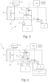
- Figure 3 schematically illustrates details of a powertrain 3 for a vehicle according to an example.
- the powertrain 3 may be comprised in a vehicle 1 as disclosed in Figure 1 .
- the powertrain 3 may be configured as disclosed in Figure 2 .
- the powertrain 3 further comprises an auxiliary cooling arrangement 70.
- the auxiliary cooling arrangement 70 may be arranged to selectively cool the drive unit 2, when the drive unit 2 is disconnected from the first cooling circuit 10.
- the control device 100 may be configured to connect the auxiliary cooling arrangement 70 with the drive unit 2, when the drive unit 2 is disconnected from the first cooling circuit 10.
- the auxiliary cooling arrangement 70 may comprise an auxiliary radiator 72 arranged in fluid communication with the drive unit 2.
- the auxiliary radiator 72 is suitably of smaller size and capacity than the first radiator 20 of the first cooling circuit 10.
- the auxiliary cooling arrangement 70 may also comprise an auxiliary fan 74 arranged in association with the auxiliary radiator 72.
- the auxiliary radiator 72 may be arranged in the bypass circuit 50.
- the auxiliary cooling arrangement 70 may thereby be connected with the drive unit 2 by controlling the first valve arrangement 40.
- first coolant 12 leaving the drive unit 2 will be directed to the bypass circuit 50 and flow through the auxiliary radiator 72 to the drive unit 2.
- the first coolant 12 in the bypass circuit 50 will thereby be cooled by the auxiliary radiator 72 and will cool the drive unit 2.
- FIG 4 schematically illustrates details of a powertrain 3 for a vehicle according to an example.
- the powertrain 3 may be comprised in a vehicle 1 as disclosed in Figure 1 .
- the powertrain 3 may be configured as disclosed in Figure 2 .
- the powertrain 3 further comprises an auxiliary cooling arrangement 70.
- the auxiliary cooling arrangement 70 may be arranged to selectively cool the drive unit 2, when the drive unit 2 is disconnected from the first cooling circuit 10.
- the control device 100 may be configured to connect the auxiliary cooling arrangement 70 with the drive unit 2, when the drive unit 2 is disconnected from the first cooling circuit 10.
- the auxiliary cooling arrangement 70 comprises a heat exchanger 76 arranged in fluid communication with the drive unit 2 and a second cooling circuit 78 with a second cooling medium 77.
- the second cooling circuit 78 is suitably colder than the first cooling circuit 10.
- the second cooling medium 77 has a lower temperature than the first coolant 12 in the first cooling circuit 10.
- the second cooling circuit 78 may comprise a pump and other components but is not part of the invention per se and is therefore illustrated with dashed lines.
- the heat exchanger 76 may be arranged in the bypass circuit.
- the second cooling circuit 78 may be arranged to be in fluid communication with the heat exchanger 76 by controlling a third valve arrangement 80.
- the auxiliary cooling arrangement 70 may thus comprise a third valve arrangement 80.
- the second cooling medium 77 may be allowed to flow through the heat exchanger 76 and thereby cool the first coolant 12 in fluid communication with the heat exchanger 76.
- the first coolant 12 in the bypass circuit 50 will thereby be cooled by the second cooling circuit 78, and will cool the drive unit 2.
- the second cooling circuit 78 may be a cooling circuit for power electronics of the vehicle 1.
- FIG 5 schematically illustrates details of a powertrain 3 for a vehicle according to an example.
- the powertrain 3 may be comprised in a vehicle 1 as disclosed in Figure 1 .
- the powertrain 3 may be configured as disclosed in Figure 2 .
- the powertrain 3 further comprises an auxiliary cooling arrangement 70.
- the auxiliary cooling arrangement 70 may be arranged to selectively cool the drive unit 2, when the drive unit 2 is disconnected from the first cooling circuit 10.
- the control device 100 may be configured to connect the auxiliary cooling arrangement 70 with the drive unit 2, when the drive unit 2 is disconnected from the first cooling circuit 10.
- the auxiliary cooling arrangement 70 comprises a second cooling circuit 78 with a second coolant 77', arranged to be in fluid communication with the drive unit 2 by controlling a fourth valve arrangement 90, so that the first coolant 12 is mixed with the second coolant 77'.
- the auxiliary cooling arrangement 70 may thereby be connected with the drive unit 2 by controlling the fourth valve arrangement 80.
- the second cooling circuit 78 may be arranged in fluid communication with the bypass circuit 50, upstream of the drive unit 2.
- second coolant 77' from the second cooling circuit 78 will mix with the first coolant 12 in the bypass circuit 50.
- the second coolant 77' suitably has a lower temperature than the first coolant 12 in the bypass circuit 50.
- the second cooling circuit 78 may be a cooling circuit for power electronics of the vehicle 1.
- the second cooling circuit 78 may comprise a pump and other components but is not part of the invention per se and is therefore illustrated with dashed lines. Some of the mixed coolant may be returned to the second cooling circuit 78 before entering the drive unit 2. Alternatively, some of the mixed coolant is returned to the second cooling circuit 78 after leaving the drive unit 2. This example is illustrated with dotted lines in the figure.
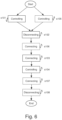
- Fig. 6 schematically illustrates a block diagram of a method for controlling a vehicle in association with a descent according to an example.
- the method relates to a vehicle as disclosed in Figure 1 and a powertrain as disclosed in Figure 2 , 3 , 4 or 5 .
- the method is performed by a control device 100 as disclosed in Figure 2-5 .
- the method comprises controlling s101 the drive unit 2 to reduce the provided propulsion power when the vehicle 1 is approaching an upcoming descent 200, which fulfils predetermined criteria; disconnecting s102 the drive unit 2 from the first cooling circuit 10; connecting s103 the auxiliary brake device 4 with the first cooling circuit 10; and controlling s104 the auxiliary brake device 4 to brake the vehicle 1 down the descent 200.
- the step of controlling s101 the drive unit 2 to reduce the provided propulsion power when the vehicle 1 is approaching an upcoming descent 200 may comprise reducing the provided propulsion power to essentially zero.
- the method may comprise identifying an upcoming descent 200, which fulfils the predetermined criteria.
- the step of controlling s101 the drive unit 2 to reduce the provided propulsion power may comprise to first identify an upcoming descent 200, which fulfils the predetermined criteria.
- the control device 100 may collect data relating to the descent 200 from various vehicle sensors, vehicle systems and map data.
- the control device 100 may further identify an upcoming descent 200, which fulfils the predetermined criteria based on this collected data.
- the predetermined criteria may comprise that the upcoming descent 200 has a certain length and/or a certain gradient.
- the vehicle 1 may have to be braked in order to avoid acceleration of the vehicle 1.
- the acceleration also depends on the vehicle weight.
- the predetermined criteria relating to the descent 200 may thus depend on the vehicle weight.
- the control device 100 may comprise a list of predetermined criteria associated with different vehicle weights, saved in a database.
- the method may thus comprise comparing the collected data relating to the descent 200 with the list to determine if the criteria are fulfilled.
- the predetermined criteria may be that the descent 200 is configured, such that the auxiliary brake device 4 is required to brake the vehicle 1 down the descent, to avoid runaway behaviour or maintain a desired vehicle speed.
- the method steps mentioned above may only be performed when the vehicle 1 is approaching a descent 200 where the auxiliary brake device 4 is required to brake the vehicle 1.
- the step of disconnecting s102 the drive unit 2 from the first cooling circuit 10 may comprise controlling the first valve arrangement 40.
- Disconnecting s102 the drive unit 2 from the first cooling circuit 10 may comprise controlling the first valve arrangement 40 to let the first coolant 12 bypass the first radiator 20.
- the step of connecting s103 the auxiliary brake device 4 with the first cooling circuit 10 may comprise controlling a second valve arrangement 60.
- connecting s103 the auxiliary brake device 4 with the first cooling circuit 10 may comprise activating the auxiliary brake device 4.
- the powertrain 3 may be configured, so that the auxiliary brake device 4 automatically is connected to the first cooling circuit 10 when the auxiliary brake device 4 is activated. It is to be understood that there may be situations where the auxiliary brake device 4 already is connected to the first cooling circuit 10 when the vehicle 1 is approaching the descent 200. In this case, the method may instead comprise ensuring that the auxiliary brake device 4 is connected with the first cooling circuit 10.
- the method may further comprise controlling s105 the powertrain 3 so that propulsive power is provided by means of an energy storage unit 300 of the powertrain 3 before the vehicle 1 has reached the top 210 of the descent 200. This way, the drive unit 2 is not required to propel the vehicle 1.
- the step of controlling s105 the powertrain 3, so that propulsion power is provided by means of an energy storage unit 300 may be performed just before, just after or essentially simultaneously as the step of controlling s101 the drive unit 2 to reduce the provided propulsion power.
- the method may also comprise connecting s106 an auxiliary cooling arrangement 70 of the powertrain 3 with the drive unit 2, when the drive unit 2 has been disconnected s102 from the first cooling circuit 10.
- Connecting s106 the auxiliary cooling arrangement 70 may comprise controlling the first valve arrangement 40 and/or a third valve arrangement 80 and/or a fourth valve arrangement 90, depending on the configuration of the auxiliary cooling arrangement 70 (se Figures 3-5 ).
- Connecting s106 the auxiliary cooling arrangement 70 with the drive unit 2 may be automatically performed when disconnecting s102 the drive unit 2 from the first cooling circuit 10, in the event that the auxiliary cooling arrangement 70 is arranged in association with the bypass circuit 50.
- the method may comprise connecting s107 the drive unit 2 with the first cooling circuit 10 when the temperature of the first coolant 12 is below the first maximum temperature of the drive unit 2.
- Connecting s107 the drive unit 2 with the first cooling circuit 10 may comprise controlling the first valve arrangement 40, so that the first coolant 12 flowing through the drive unit 2 is allowed to flow through the first radiator 20.
- the method may also comprise disconnecting s108 the auxiliary brake device 4 from the first cooling circuit 10, when the auxiliary brake device 4 no longer is operating.
- Disconnecting s108 the auxiliary brake device 4 from the first cooling circuit 10 may comprise controlling the second valve arrangement 60 or it may comprise deactivating the auxiliary brake device 4, whereby it is automatically disconnected from the first cooling circuit 10.
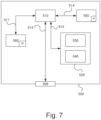
- FIG. 7 is a diagram of a version of a device 500.
- the control device 100 described with reference to Figures 2-5 may in a version comprise the device 500.
- the device 500 comprises a non-volatile memory 520, a data processing unit 510 and a read/write memory 550.
- the non-volatile memory 520 has a first memory element 530 in which a computer programme, e.g. an operating system, is stored for controlling the function of the device 500.
- the device 500 further comprises a bus controller, a serial communication port, I/O means, an A/D converter, a time and date input and transfer unit, an event counter and an interruption controller (not depicted).
- the non-volatile memory 520 has also a second memory element 540.
- a computer programme P which comprises routines for controlling a vehicle in association with a descent.
- the computer programme P further comprises routines for controlling the drive unit to reduce provided propulsion power when the vehicle is approaching an upcoming descent, which fulfils predetermined criteria; disconnecting the drive unit from the first cooling circuit; connecting the auxiliary brake device with the first cooling circuit; and controlling the auxiliary brake device to brake the vehicle down the descent.
- the computer programme P may also comprise routines for controlling the powertrain to provide propulsion power by means of an energy storage unit of the powertrain before the vehicle has reached the top of the descent.
- the computer programme P may also comprise routines for connecting the drive unit with the first cooling circuit when the temperature of the first coolant is below the first maximum temperature of the drive unit.
- the computer programme P may also comprise routines for connecting an auxiliary cooling arrangement with the drive unit, when the drive unit is disconnected from the first cooling circuit.
- the programme P may be stored in an executable form or in a compressed form in a memory 560 and/or in a read/write memory 550.
- the data processing unit 510 is described as performing a certain function, it means that the data processing unit 510 effects a certain part of the programme stored in the memory 560 or a certain part of the programme stored in the read/write memory 550.
- the data processing device 510 can communicate with a data port 599 via a data bus 515.
- the non-volatile memory 520 is intended for communication with the data processing unit 510 via a data bus 512.
- the separate memory 560 is intended to communicate with the data processing unit 510 via a data bus 511.
- the read/write memory 550 is adapted to communicating with the data processing unit 510 via a data bus 514.
- Parts of the methods herein described may be effected by the device 500 by means of the data processing unit 510, which runs the programme stored in the memory 560 or the read/write memory 550. When the device 500 runs the programme, methods herein described are executed.
Landscapes
- Engineering & Computer Science (AREA)
- Mechanical Engineering (AREA)
- Transportation (AREA)
- Chemical & Material Sciences (AREA)
- Combustion & Propulsion (AREA)
- General Engineering & Computer Science (AREA)
- Automation & Control Theory (AREA)
- Life Sciences & Earth Sciences (AREA)
- Human Computer Interaction (AREA)
- Sustainable Development (AREA)
- Sustainable Energy (AREA)
- Power Engineering (AREA)
- Electric Propulsion And Braking For Vehicles (AREA)
- Hybrid Electric Vehicles (AREA)
- Regulating Braking Force (AREA)
- Cooling, Air Intake And Gas Exhaust, And Fuel Tank Arrangements In Propulsion Units (AREA)
Claims (16)
- Verfahren, das von einer Steuervorrichtung (100) zum Steuern eines Fahrzeugs (1) in Verbindung mit einer Abfahrt (200) ausgeführt wird, wobei das Fahrzeug (1) einen Antriebsstrang (3) aufweist, der umfasst:eine Antriebseinheit (2), die zum Bereitstellen einer Antriebsleistung eingerichtet ist;eine Zusatzbremsvorrichtung (4); undeinen ersten Kühlkreislauf (10), der ein erstes Kühlmittel (12) umfasst;wobei die Antriebseinheit (2) und die Zusatzbremsvorrichtung (4) derart angeordnet sind, dass sie selektiv mit dem ersten Kühlkreislauf (10) verbunden oder von diesem getrennt werden können, wobei die Antriebseinheit (2) eine erste Höchsttemperatur aufweist und die Zusatzbremsvorrichtung (4) eine zweite Höchsttemperatur aufweist, die höher ist als die erste Höchsttemperatur,wobei das Verfahren umfasst:Identifizieren einer bevorstehenden Abfahrt (200), die vorbestimmte Kriterien erfüllt, undSteuern (s101) der Antriebseinheit (2), um die bereitgestellte Antriebsleistung zu reduzieren, wenn sich das Fahrzeug (1) der Abfahrt (200) nähert;Trennen (s102) der Antriebseinheit (2) von dem ersten Kühlkreislauf (10);Verbinden (s103) der Zusatzbremsvorrichtung (4) mit dem ersten Kühlkreislauf (10); undSteuern (s104) der Zusatzbremsvorrichtung (4) zum Abbremsen des Fahrzeugs (1) auf der Abfahrt (200).
- Verfahren nach Anspruch 1, wobei die vorbestimmten Kriterien umfassen, dass die bevorstehende Abfahrt (200) eine bestimmte Länge und/oder ein bestimmtes Gefälle aufweist.
- Verfahren nach Anspruch 1 oder 2, wobei das Trennen (s102) der Antriebseinheit (2) von dem ersten Kühlkreislauf (10) das Steuern einer ersten Ventilanordnung (40) umfasst.
- Verfahren nach einem der vorangehenden Ansprüche, wobei das Verbinden (s103) der Zusatzbremsvorrichtung (4) mit dem ersten Kühlkreislauf (10) das Steuern einer zweiten Ventilanordnung (60) umfasst.
- Verfahren nach einem der vorangehenden Ansprüche, das ferner umfasst:
Steuern (s105) des Antriebsstrangs (3), um Antriebsleistung mittels einer Energiespeichereinheit (300) des Antriebsstrangs (3) bereitzustellen, bevor das Fahrzeug (1) den Anfang (210) der Abfahrt (200) erreicht hat. - Verfahren nach einem der vorangehenden Ansprüche, das ferner umfasst:
Verbinden (s107) der Antriebseinheit (2) mit dem ersten Kühlkreislauf (10), wenn die Temperatur des ersten Kühlmittels (12) unter der ersten Höchsttemperatur der Antriebseinheit (2) liegt. - Verfahren nach einem der vorangehenden Ansprüche, das ferner umfasst:
Verbinden (s106) einer Zusatzkühlanordnung (70) des Antriebsstrangs (3) mit der Antriebseinheit (2), wenn die Antriebseinheit (2) von dem ersten Kühlkreislauf (10) getrennt wird. - Antriebsstrang (3) für ein Fahrzeug (1), wobei der Antriebsstrang (3) umfasst:eine Antriebseinheit (2), die zum Bereitstellen einer Antriebsleistung eingerichtet ist;eine Zusatzbremsvorrichtung (4); undeinen ersten Kühlkreislauf (10), der ein erstes Kühlmittel (12) umfasst;wobei die Antriebseinheit (2) und die Zusatzbremsvorrichtung (4) derart angeordnet sind, dass sie selektiv mit dem ersten Kühlkreislauf (10) verbunden oder von diesem getrennt werden können, wobei die Antriebseinheit (2) eine erste Höchsttemperatur aufweist und die Zusatzbremsvorrichtung (4) eine zweite Höchsttemperatur aufweist, die höher ist als die erste Höchsttemperatur, wobei der Antriebsstrang (3) ferner eine Steuervorrichtung (100) umfasst, die eingerichtet ist zum:Steuern der Antriebseinheit (2), um die bereitgestellte Antriebsleistung zu reduzieren,wenn sich das Fahrzeug (1) einer bevorstehenden Abfahrt (200) nähert, die vorbestimmte Kriterien erfüllt;Trennen der Antriebseinheit (2) von dem ersten Kühlkreislauf (10);Verbinden der Zusatzbremsvorrichtung (4) mit dem ersten Kühlkreislauf (10); undSteuern der Zusatzbremsvorrichtung (4) zum Abbremsen des Fahrzeugs (1) auf der Abfahrt (200).
- Antriebsstrang (3) nach Anspruch 8, der ferner umfasst:
eine Energiespeichereinheit (300),
wobei die Steuervorrichtung (100) dazu eingerichtet ist, die Energiespeichereinheit (300) zum Bereitstellen einer Antriebsleistung zu steuern, bevor das Fahrzeug (1) den Gipfel (210) der bevorstehenden Abfahrt (200) erreicht hat. - Antriebsstrang (3) nach Anspruch 8 oder 9, wobei die Steuervorrichtung (100) dazu eingerichtet ist, die Antriebseinheit (2) mit dem ersten Kühlkreislauf (10) zu verbinden, wenn die Temperatur des ersten Kühlmittels (12) unter der ersten Höchsttemperatur der Antriebseinheit (2) liegt.
- Antriebsstrang (3) nach einem der Ansprüche 8-10, der ferner umfasst:
eine Zusatzkühlanordnung (70),
wobei die Steuervorrichtung (100) dazu eingerichtet ist, die Zusatzkühlanordnung (70) mit der Antriebseinheit (2) zu verbinden, wenn die Antriebseinheit (2) von dem ersten Kühlkreislauf (10) getrennt wird. - Antriebsstrang (3) nach Anspruch 11, wobei die Zusatzkühlanordnung (70) einen Zusatzkühler (72) umfasst, der in Fluidverbindung mit der Antriebseinheit (2) angeordnet ist.
- Antriebsstrang (3) nach Anspruch 11, wobei die Zusatzkühlanordnung (70) einen Wärmetauscher (76), der in Fluidverbindung mit der Antriebseinheit (2) angeordnet ist, und einen zweiten Kühlkreislauf (78) mit einem zweiten Kühlmedium (77) umfasst.
- Antriebsstrang (3) nach einem der Ansprüche 8-13, wobei die Antriebseinheit (2) eine Brennstoffzelle umfasst.
- Antriebsstrang (3) nach einem der Ansprüche 8-13, wobei die Zusatzbremsvorrichtung (4) einen Retarder umfasst.
- Fahrzeug (1) mit einem Antriebsstrang (3) nach einem der Ansprüche 8-15.
Applications Claiming Priority (2)
| Application Number | Priority Date | Filing Date | Title |
|---|---|---|---|
| SE1950294A SE543280C2 (en) | 2019-03-08 | 2019-03-08 | A method for controlling a vehicle in association with a descent, a powertrain, a vehicle, a computer program and a computer-readable medium |
| PCT/SE2020/050146 WO2020185138A1 (en) | 2019-03-08 | 2020-02-12 | A method for controlling a vehicle in association with a descent, a powertrain, a vehicle, a computer program and a computer-readable medium |
Publications (3)
| Publication Number | Publication Date |
|---|---|
| EP3934954A1 EP3934954A1 (de) | 2022-01-12 |
| EP3934954A4 EP3934954A4 (de) | 2022-11-16 |
| EP3934954B1 true EP3934954B1 (de) | 2024-10-23 |
Family
ID=72426805
Family Applications (1)
| Application Number | Title | Priority Date | Filing Date |
|---|---|---|---|
| EP20771036.9A Active EP3934954B1 (de) | 2019-03-08 | 2020-02-12 | Verfahren zur steuerung eines fahrzeugs in verbindung mit einer abfahrt, antriebsstrang und fahrzeug |
Country Status (5)
| Country | Link |
|---|---|
| US (1) | US11884275B2 (de) |
| EP (1) | EP3934954B1 (de) |
| CN (1) | CN113423624B (de) |
| SE (1) | SE543280C2 (de) |
| WO (1) | WO2020185138A1 (de) |
Families Citing this family (9)
| Publication number | Priority date | Publication date | Assignee | Title |
|---|---|---|---|---|
| DE102021203125A1 (de) | 2020-11-04 | 2022-05-05 | Mahle International Gmbh | Elektrisch angetriebenes Kraftfahrzeug |
| KR20220139758A (ko) * | 2021-04-08 | 2022-10-17 | 현대자동차주식회사 | 차량용 열관리시스템의 난방 제어방법 |
| DE102021113447A1 (de) | 2021-05-25 | 2022-12-01 | Voith Patent Gmbh | Kühlsystem für ein Kraftfahrzeug mit E-Antriebsstrang |
| DE102021118975B4 (de) | 2021-07-22 | 2024-12-05 | Audi Aktiengesellschaft | Kühlsystem, Brennstoffzellenfahrzeug und Verfahren zum Betreiben eines Kühlsystems |
| JP7484854B2 (ja) * | 2021-09-14 | 2024-05-16 | トヨタ自動車株式会社 | 車両運転支援装置、車両運転支援方法及び車両運転支援プログラム |
| EP4155106B1 (de) | 2021-09-22 | 2024-07-03 | Volvo Truck Corporation | Kühlsystem für ein fahrzeug |
| DE102021214728A1 (de) | 2021-12-20 | 2023-06-22 | Mahle International Gmbh | Kühlsystem |
| DE102022131333B4 (de) * | 2022-11-28 | 2025-09-04 | Schaeffler Technologies AG & Co. KG | Thermomanagement-System für ein elektrisch betriebenes Kraftfahrzeug |
| CN116729138B (zh) * | 2023-06-29 | 2025-09-12 | 厦门金龙联合汽车工业有限公司 | 一种复合制动减速度控制方法 |
Family Cites Families (18)
| Publication number | Priority date | Publication date | Assignee | Title |
|---|---|---|---|---|
| DE19641558A1 (de) | 1996-10-09 | 1998-04-16 | Voith Turbo Kg | Verfahren und Steuerung zur Regelung des Kühlkreislaufes eines Fahrzeuges mittels einer thermisch geregelten Wasserpumpe |
| SE0300923L (sv) | 2003-03-28 | 2004-02-24 | Scania Cv Abp | Kylanordning och sätt att kyla en retarder |
| JP2006233919A (ja) * | 2005-02-28 | 2006-09-07 | Fuji Heavy Ind Ltd | ハイブリッド車両の駆動装置 |
| DE102006036186A1 (de) * | 2006-08-01 | 2007-10-11 | Voith Turbo Gmbh & Co. Kg | Fahrzeugkühlkreislauf zur Kühlung eines Antriebsmotors und einer hydrodynamischen Bremse |
| BRPI0806669A2 (pt) * | 2007-01-23 | 2014-05-27 | Volvo Lastvagnar Ab | Um método para controle de refrigeração de um freio auxiliar |
| DE102007054246A1 (de) * | 2007-11-14 | 2009-05-20 | Daimler Ag | Brennstoffzellenantrieb für ein Kraftfahrzeug |
| SE535564C2 (sv) * | 2010-12-22 | 2012-09-25 | Scania Cv Ab | Kylsystem i ett fordon |
| US8897983B2 (en) * | 2011-02-15 | 2014-11-25 | Deere & Company | System and method for using vehicle parasitic loads to aid with vehicle speed retardation |
| DE102011101395A1 (de) * | 2011-05-13 | 2012-11-15 | Daimler Ag | Verfahren zur Optimierung eines Leistungsbedarfs eines Kraftfahrzeugs |
| DE102012205141A1 (de) | 2012-03-29 | 2013-10-02 | Zf Friedrichshafen Ag | Fluidversorgungsanordnung für ein Hybridfahrzeug |
| SE539027C2 (sv) | 2013-04-25 | 2017-03-21 | Scania Cv Ab | Förfarande och system för styrning av ett kylsystem |
| SE538626C2 (sv) * | 2013-10-24 | 2016-10-04 | Scania Cv Ab | Kylsystem i ett fordon |
| KR101592652B1 (ko) | 2013-12-30 | 2016-02-12 | 현대자동차주식회사 | 연료전지 차량의 열 관리 시스템 및 방법 |
| EP3137747B1 (de) * | 2014-04-30 | 2020-10-14 | Cummins, Inc. | Fahrzeug mit einem retarder (dauerbremse) und verfahren zum steuern eines kühlmittels in einem retarder |
| JP6260516B2 (ja) | 2014-11-14 | 2018-01-17 | トヨタ自動車株式会社 | 燃料電池システムおよび燃料電池搭載車両 |
| KR101755480B1 (ko) | 2015-12-10 | 2017-07-10 | 현대자동차 주식회사 | 차량용 쿨링팬 제어방법 |
| CN105508020B (zh) | 2016-02-01 | 2018-05-29 | 清华大学 | 发动机和制动电阻的共用冷却系统 |
| SE540085C2 (en) * | 2016-07-12 | 2018-03-20 | Scania Cv Ab | A method for controlling a waste heat recovery system and such a waste heat recovery system |
-
2019
- 2019-03-08 SE SE1950294A patent/SE543280C2/en unknown
-
2020
- 2020-02-12 US US17/427,415 patent/US11884275B2/en active Active
- 2020-02-12 CN CN202080012739.8A patent/CN113423624B/zh active Active
- 2020-02-12 EP EP20771036.9A patent/EP3934954B1/de active Active
- 2020-02-12 WO PCT/SE2020/050146 patent/WO2020185138A1/en not_active Ceased
Also Published As
| Publication number | Publication date |
|---|---|
| SE1950294A1 (en) | 2020-09-09 |
| CN113423624A (zh) | 2021-09-21 |
| CN113423624B (zh) | 2024-12-13 |
| EP3934954A4 (de) | 2022-11-16 |
| EP3934954A1 (de) | 2022-01-12 |
| US11884275B2 (en) | 2024-01-30 |
| WO2020185138A1 (en) | 2020-09-17 |
| US20220097705A1 (en) | 2022-03-31 |
| SE543280C2 (en) | 2020-11-10 |
Similar Documents
| Publication | Publication Date | Title |
|---|---|---|
| EP3934954B1 (de) | Verfahren zur steuerung eines fahrzeugs in verbindung mit einer abfahrt, antriebsstrang und fahrzeug | |
| CA2899498C (en) | System and method for engine driveline disconnect during regeneration in hybrid vehicles | |
| US20170282910A1 (en) | Limp home mode drive method and system for hybrid vehicle | |
| EP3720732B1 (de) | Kühlmittelsystem für ein fahrzeug | |
| JP7424836B2 (ja) | 車両の冷却構造 | |
| EP2935821B1 (de) | Kühlsystem für ein mechanisch und hydraulisch angetriebenes hybridfahrzeug | |
| CN114435113A (zh) | 电动汽车 | |
| CN114269587A (zh) | 用于监控油冷却回路中的油流的方法 | |
| SE545818C2 (en) | Coolant Circuit, Hydrodynamic Retarder Arrangement, and Vehicle | |
| EP4212371A1 (de) | Wärmemanagementsystem für ein fahrzeug | |
| EP4113704B1 (de) | Kühlsystem und verfahren zur steuerung eines kühlsystems | |
| EP4446618A1 (de) | Ölsystem, steuerungsvorrichtung und verfahren zur steuerung der ölzufuhr zu einer elektrischen maschine | |
| JP3889396B2 (ja) | ハイブリッド車両の冷却装置 | |
| US12286031B2 (en) | Cooling system in a fuel cell electric vehicle and method of controlling a cooling system in a fuel cell electric vehicle | |
| SE2251345A1 (en) | Method of Controlling Operation of Vehicle Cooling System, Computer Program, Computer-readable Medium, Control Arrangement, Vehicle Cooling System, and Vehicle | |
| EP4656470A1 (de) | Bremseinheit | |
| KR102948501B1 (ko) | 전기차의 모터 냉각 및 액추에이터 통합 제어 시스템 | |
| EP3572264A1 (de) | Elektrischer antriebsstrang, verfahren zur steuerung der temperatur eines kühlmittels eines elektrischen antriebsstrangs und entsprechende vorrichtungen | |
| JP2022059884A (ja) | ハイブリッド車両 | |
| CN118786043A (zh) | 车辆的热管理系统 | |
| BG65420B1 (bg) | Система за охлаждане на хибридни превозни средства |
Legal Events
| Date | Code | Title | Description |
|---|---|---|---|
| STAA | Information on the status of an ep patent application or granted ep patent |
Free format text: STATUS: THE INTERNATIONAL PUBLICATION HAS BEEN MADE |
|
| PUAI | Public reference made under article 153(3) epc to a published international application that has entered the european phase |
Free format text: ORIGINAL CODE: 0009012 |
|
| STAA | Information on the status of an ep patent application or granted ep patent |
Free format text: STATUS: REQUEST FOR EXAMINATION WAS MADE |
|
| 17P | Request for examination filed |
Effective date: 20211008 |
|
| AK | Designated contracting states |
Kind code of ref document: A1 Designated state(s): AL AT BE BG CH CY CZ DE DK EE ES FI FR GB GR HR HU IE IS IT LI LT LU LV MC MK MT NL NO PL PT RO RS SE SI SK SM TR |
|
| DAV | Request for validation of the european patent (deleted) | ||
| DAX | Request for extension of the european patent (deleted) | ||
| A4 | Supplementary search report drawn up and despatched |
Effective date: 20221017 |
|
| RIC1 | Information provided on ipc code assigned before grant |
Ipc: B60W 50/00 20060101ALI20221011BHEP Ipc: B60W 30/18 20120101ALI20221011BHEP Ipc: F16D 65/78 20060101ALI20221011BHEP Ipc: F01P 7/14 20060101ALI20221011BHEP Ipc: B60W 40/02 20060101ALI20221011BHEP Ipc: B60W 10/18 20120101AFI20221011BHEP |
|
| P01 | Opt-out of the competence of the unified patent court (upc) registered |
Effective date: 20230518 |
|
| GRAP | Despatch of communication of intention to grant a patent |
Free format text: ORIGINAL CODE: EPIDOSNIGR1 |
|
| STAA | Information on the status of an ep patent application or granted ep patent |
Free format text: STATUS: GRANT OF PATENT IS INTENDED |
|
| INTG | Intention to grant announced |
Effective date: 20240524 |
|
| GRAS | Grant fee paid |
Free format text: ORIGINAL CODE: EPIDOSNIGR3 |
|
| GRAA | (expected) grant |
Free format text: ORIGINAL CODE: 0009210 |
|
| STAA | Information on the status of an ep patent application or granted ep patent |
Free format text: STATUS: THE PATENT HAS BEEN GRANTED |
|
| AK | Designated contracting states |
Kind code of ref document: B1 Designated state(s): AL AT BE BG CH CY CZ DE DK EE ES FI FR GB GR HR HU IE IS IT LI LT LU LV MC MK MT NL NO PL PT RO RS SE SI SK SM TR |
|
| REG | Reference to a national code |
Ref country code: GB Ref legal event code: FG4D |
|
| REG | Reference to a national code |
Ref country code: CH Ref legal event code: EP |
|
| REG | Reference to a national code |
Ref country code: DE Ref legal event code: R096 Ref document number: 602020039954 Country of ref document: DE |
|
| REG | Reference to a national code |
Ref country code: IE Ref legal event code: FG4D |
|
| REG | Reference to a national code |
Ref country code: SE Ref legal event code: TRGR |
|
| REG | Reference to a national code |
Ref country code: LT Ref legal event code: MG9D |
|
| REG | Reference to a national code |
Ref country code: NL Ref legal event code: MP Effective date: 20241023 |
|
| REG | Reference to a national code |
Ref country code: AT Ref legal event code: MK05 Ref document number: 1734609 Country of ref document: AT Kind code of ref document: T Effective date: 20241023 |
|
| PG25 | Lapsed in a contracting state [announced via postgrant information from national office to epo] |
Ref country code: NL Free format text: LAPSE BECAUSE OF FAILURE TO SUBMIT A TRANSLATION OF THE DESCRIPTION OR TO PAY THE FEE WITHIN THE PRESCRIBED TIME-LIMIT Effective date: 20241023 |
|
| PG25 | Lapsed in a contracting state [announced via postgrant information from national office to epo] |
Ref country code: NL Free format text: LAPSE BECAUSE OF FAILURE TO SUBMIT A TRANSLATION OF THE DESCRIPTION OR TO PAY THE FEE WITHIN THE PRESCRIBED TIME-LIMIT Effective date: 20241023 |
|
| PG25 | Lapsed in a contracting state [announced via postgrant information from national office to epo] |
Ref country code: PT Free format text: LAPSE BECAUSE OF FAILURE TO SUBMIT A TRANSLATION OF THE DESCRIPTION OR TO PAY THE FEE WITHIN THE PRESCRIBED TIME-LIMIT Effective date: 20250224 Ref country code: HR Free format text: LAPSE BECAUSE OF FAILURE TO SUBMIT A TRANSLATION OF THE DESCRIPTION OR TO PAY THE FEE WITHIN THE PRESCRIBED TIME-LIMIT Effective date: 20241023 Ref country code: IS Free format text: LAPSE BECAUSE OF FAILURE TO SUBMIT A TRANSLATION OF THE DESCRIPTION OR TO PAY THE FEE WITHIN THE PRESCRIBED TIME-LIMIT Effective date: 20250223 |
|
| PG25 | Lapsed in a contracting state [announced via postgrant information from national office to epo] |
Ref country code: FI Free format text: LAPSE BECAUSE OF FAILURE TO SUBMIT A TRANSLATION OF THE DESCRIPTION OR TO PAY THE FEE WITHIN THE PRESCRIBED TIME-LIMIT Effective date: 20241023 |
|
| PG25 | Lapsed in a contracting state [announced via postgrant information from national office to epo] |
Ref country code: BG Free format text: LAPSE BECAUSE OF FAILURE TO SUBMIT A TRANSLATION OF THE DESCRIPTION OR TO PAY THE FEE WITHIN THE PRESCRIBED TIME-LIMIT Effective date: 20241023 |
|
| PG25 | Lapsed in a contracting state [announced via postgrant information from national office to epo] |
Ref country code: ES Free format text: LAPSE BECAUSE OF FAILURE TO SUBMIT A TRANSLATION OF THE DESCRIPTION OR TO PAY THE FEE WITHIN THE PRESCRIBED TIME-LIMIT Effective date: 20241023 |
|
| PG25 | Lapsed in a contracting state [announced via postgrant information from national office to epo] |
Ref country code: NO Free format text: LAPSE BECAUSE OF FAILURE TO SUBMIT A TRANSLATION OF THE DESCRIPTION OR TO PAY THE FEE WITHIN THE PRESCRIBED TIME-LIMIT Effective date: 20250123 |
|
| PG25 | Lapsed in a contracting state [announced via postgrant information from national office to epo] |
Ref country code: LV Free format text: LAPSE BECAUSE OF FAILURE TO SUBMIT A TRANSLATION OF THE DESCRIPTION OR TO PAY THE FEE WITHIN THE PRESCRIBED TIME-LIMIT Effective date: 20241023 Ref country code: GR Free format text: LAPSE BECAUSE OF FAILURE TO SUBMIT A TRANSLATION OF THE DESCRIPTION OR TO PAY THE FEE WITHIN THE PRESCRIBED TIME-LIMIT Effective date: 20250124 Ref country code: AT Free format text: LAPSE BECAUSE OF FAILURE TO SUBMIT A TRANSLATION OF THE DESCRIPTION OR TO PAY THE FEE WITHIN THE PRESCRIBED TIME-LIMIT Effective date: 20241023 |
|
| PG25 | Lapsed in a contracting state [announced via postgrant information from national office to epo] |
Ref country code: PL Free format text: LAPSE BECAUSE OF FAILURE TO SUBMIT A TRANSLATION OF THE DESCRIPTION OR TO PAY THE FEE WITHIN THE PRESCRIBED TIME-LIMIT Effective date: 20241023 |
|
| PG25 | Lapsed in a contracting state [announced via postgrant information from national office to epo] |
Ref country code: RS Free format text: LAPSE BECAUSE OF FAILURE TO SUBMIT A TRANSLATION OF THE DESCRIPTION OR TO PAY THE FEE WITHIN THE PRESCRIBED TIME-LIMIT Effective date: 20250123 |
|
| PG25 | Lapsed in a contracting state [announced via postgrant information from national office to epo] |
Ref country code: SM Free format text: LAPSE BECAUSE OF FAILURE TO SUBMIT A TRANSLATION OF THE DESCRIPTION OR TO PAY THE FEE WITHIN THE PRESCRIBED TIME-LIMIT Effective date: 20241023 |
|
| PG25 | Lapsed in a contracting state [announced via postgrant information from national office to epo] |
Ref country code: DK Free format text: LAPSE BECAUSE OF FAILURE TO SUBMIT A TRANSLATION OF THE DESCRIPTION OR TO PAY THE FEE WITHIN THE PRESCRIBED TIME-LIMIT Effective date: 20241023 |
|
| PG25 | Lapsed in a contracting state [announced via postgrant information from national office to epo] |
Ref country code: EE Free format text: LAPSE BECAUSE OF FAILURE TO SUBMIT A TRANSLATION OF THE DESCRIPTION OR TO PAY THE FEE WITHIN THE PRESCRIBED TIME-LIMIT Effective date: 20241023 |
|
| PG25 | Lapsed in a contracting state [announced via postgrant information from national office to epo] |
Ref country code: RO Free format text: LAPSE BECAUSE OF FAILURE TO SUBMIT A TRANSLATION OF THE DESCRIPTION OR TO PAY THE FEE WITHIN THE PRESCRIBED TIME-LIMIT Effective date: 20241023 |
|
| REG | Reference to a national code |
Ref country code: DE Ref legal event code: R097 Ref document number: 602020039954 Country of ref document: DE |
|
| PG25 | Lapsed in a contracting state [announced via postgrant information from national office to epo] |
Ref country code: SK Free format text: LAPSE BECAUSE OF FAILURE TO SUBMIT A TRANSLATION OF THE DESCRIPTION OR TO PAY THE FEE WITHIN THE PRESCRIBED TIME-LIMIT Effective date: 20241023 |
|
| PG25 | Lapsed in a contracting state [announced via postgrant information from national office to epo] |
Ref country code: CZ Free format text: LAPSE BECAUSE OF FAILURE TO SUBMIT A TRANSLATION OF THE DESCRIPTION OR TO PAY THE FEE WITHIN THE PRESCRIBED TIME-LIMIT Effective date: 20241023 |
|
| PG25 | Lapsed in a contracting state [announced via postgrant information from national office to epo] |
Ref country code: IT Free format text: LAPSE BECAUSE OF FAILURE TO SUBMIT A TRANSLATION OF THE DESCRIPTION OR TO PAY THE FEE WITHIN THE PRESCRIBED TIME-LIMIT Effective date: 20241023 |
|
| PLBE | No opposition filed within time limit |
Free format text: ORIGINAL CODE: 0009261 |
|
| STAA | Information on the status of an ep patent application or granted ep patent |
Free format text: STATUS: NO OPPOSITION FILED WITHIN TIME LIMIT |
|
| PG25 | Lapsed in a contracting state [announced via postgrant information from national office to epo] |
Ref country code: MC Free format text: LAPSE BECAUSE OF FAILURE TO SUBMIT A TRANSLATION OF THE DESCRIPTION OR TO PAY THE FEE WITHIN THE PRESCRIBED TIME-LIMIT Effective date: 20241023 |
|
| REG | Reference to a national code |
Ref country code: CH Ref legal event code: PL |
|
| 26N | No opposition filed |
Effective date: 20250724 |
|
| PG25 | Lapsed in a contracting state [announced via postgrant information from national office to epo] |
Ref country code: LU Free format text: LAPSE BECAUSE OF NON-PAYMENT OF DUE FEES Effective date: 20250212 |
|
| PG25 | Lapsed in a contracting state [announced via postgrant information from national office to epo] |
Ref country code: CH Free format text: LAPSE BECAUSE OF NON-PAYMENT OF DUE FEES Effective date: 20250228 |
|
| PGFP | Annual fee paid to national office [announced via postgrant information from national office to epo] |
Ref country code: FR Payment date: 20251231 Year of fee payment: 7 |
|
| PG25 | Lapsed in a contracting state [announced via postgrant information from national office to epo] |
Ref country code: IE Free format text: LAPSE BECAUSE OF NON-PAYMENT OF DUE FEES Effective date: 20250212 |
|
| PGFP | Annual fee paid to national office [announced via postgrant information from national office to epo] |
Ref country code: SE Payment date: 20251230 Year of fee payment: 7 |
|
| PGFP | Annual fee paid to national office [announced via postgrant information from national office to epo] |
Ref country code: GB Payment date: 20260106 Year of fee payment: 7 |
|
| PGFP | Annual fee paid to national office [announced via postgrant information from national office to epo] |
Ref country code: DE Payment date: 20251230 Year of fee payment: 7 |
|
| PGFP | Annual fee paid to national office [announced via postgrant information from national office to epo] |
Ref country code: BE Payment date: 20260105 Year of fee payment: 7 |