EP3936306B1 - Procédé d'impression 3d de type à production continue - Google Patents
Procédé d'impression 3d de type à production continue Download PDFInfo
- Publication number
- EP3936306B1 EP3936306B1 EP20909566.0A EP20909566A EP3936306B1 EP 3936306 B1 EP3936306 B1 EP 3936306B1 EP 20909566 A EP20909566 A EP 20909566A EP 3936306 B1 EP3936306 B1 EP 3936306B1
- Authority
- EP
- European Patent Office
- Prior art keywords
- ink composition
- printed matter
- conveyor belt
- printing method
- printing
- Prior art date
- Legal status (The legal status is an assumption and is not a legal conclusion. Google has not performed a legal analysis and makes no representation as to the accuracy of the status listed.)
- Active
Links
Images

Classifications
-
- B—PERFORMING OPERATIONS; TRANSPORTING
- B29—WORKING OF PLASTICS; WORKING OF SUBSTANCES IN A PLASTIC STATE IN GENERAL
- B29C—SHAPING OR JOINING OF PLASTICS; SHAPING OF MATERIAL IN A PLASTIC STATE, NOT OTHERWISE PROVIDED FOR; AFTER-TREATMENT OF THE SHAPED PRODUCTS, e.g. REPAIRING
- B29C64/00—Additive manufacturing, i.e. manufacturing of three-dimensional [3D] objects by additive deposition, additive agglomeration or additive layering, e.g. by 3D printing, stereolithography or selective laser sintering
- B29C64/30—Auxiliary operations or equipment
- B29C64/379—Handling of additively manufactured objects, e.g. using robots
-
- B—PERFORMING OPERATIONS; TRANSPORTING
- B29—WORKING OF PLASTICS; WORKING OF SUBSTANCES IN A PLASTIC STATE IN GENERAL
- B29C—SHAPING OR JOINING OF PLASTICS; SHAPING OF MATERIAL IN A PLASTIC STATE, NOT OTHERWISE PROVIDED FOR; AFTER-TREATMENT OF THE SHAPED PRODUCTS, e.g. REPAIRING
- B29C64/00—Additive manufacturing, i.e. manufacturing of three-dimensional [3D] objects by additive deposition, additive agglomeration or additive layering, e.g. by 3D printing, stereolithography or selective laser sintering
- B29C64/10—Processes of additive manufacturing
-
- B—PERFORMING OPERATIONS; TRANSPORTING
- B29—WORKING OF PLASTICS; WORKING OF SUBSTANCES IN A PLASTIC STATE IN GENERAL
- B29C—SHAPING OR JOINING OF PLASTICS; SHAPING OF MATERIAL IN A PLASTIC STATE, NOT OTHERWISE PROVIDED FOR; AFTER-TREATMENT OF THE SHAPED PRODUCTS, e.g. REPAIRING
- B29C64/00—Additive manufacturing, i.e. manufacturing of three-dimensional [3D] objects by additive deposition, additive agglomeration or additive layering, e.g. by 3D printing, stereolithography or selective laser sintering
- B29C64/10—Processes of additive manufacturing
- B29C64/106—Processes of additive manufacturing using only liquids or viscous materials, e.g. depositing a continuous bead of viscous material
- B29C64/124—Processes of additive manufacturing using only liquids or viscous materials, e.g. depositing a continuous bead of viscous material using layers of liquid which are selectively solidified
-
- B—PERFORMING OPERATIONS; TRANSPORTING
- B29—WORKING OF PLASTICS; WORKING OF SUBSTANCES IN A PLASTIC STATE IN GENERAL
- B29C—SHAPING OR JOINING OF PLASTICS; SHAPING OF MATERIAL IN A PLASTIC STATE, NOT OTHERWISE PROVIDED FOR; AFTER-TREATMENT OF THE SHAPED PRODUCTS, e.g. REPAIRING
- B29C64/00—Additive manufacturing, i.e. manufacturing of three-dimensional [3D] objects by additive deposition, additive agglomeration or additive layering, e.g. by 3D printing, stereolithography or selective laser sintering
- B29C64/20—Apparatus for additive manufacturing; Details thereof or accessories therefor
- B29C64/245—Platforms or substrates
-
- B—PERFORMING OPERATIONS; TRANSPORTING
- B29—WORKING OF PLASTICS; WORKING OF SUBSTANCES IN A PLASTIC STATE IN GENERAL
- B29C—SHAPING OR JOINING OF PLASTICS; SHAPING OF MATERIAL IN A PLASTIC STATE, NOT OTHERWISE PROVIDED FOR; AFTER-TREATMENT OF THE SHAPED PRODUCTS, e.g. REPAIRING
- B29C64/00—Additive manufacturing, i.e. manufacturing of three-dimensional [3D] objects by additive deposition, additive agglomeration or additive layering, e.g. by 3D printing, stereolithography or selective laser sintering
- B29C64/30—Auxiliary operations or equipment
- B29C64/35—Cleaning
-
- B—PERFORMING OPERATIONS; TRANSPORTING
- B29—WORKING OF PLASTICS; WORKING OF SUBSTANCES IN A PLASTIC STATE IN GENERAL
- B29C—SHAPING OR JOINING OF PLASTICS; SHAPING OF MATERIAL IN A PLASTIC STATE, NOT OTHERWISE PROVIDED FOR; AFTER-TREATMENT OF THE SHAPED PRODUCTS, e.g. REPAIRING
- B29C64/00—Additive manufacturing, i.e. manufacturing of three-dimensional [3D] objects by additive deposition, additive agglomeration or additive layering, e.g. by 3D printing, stereolithography or selective laser sintering
- B29C64/30—Auxiliary operations or equipment
- B29C64/357—Recycling
-
- B—PERFORMING OPERATIONS; TRANSPORTING
- B29—WORKING OF PLASTICS; WORKING OF SUBSTANCES IN A PLASTIC STATE IN GENERAL
- B29C—SHAPING OR JOINING OF PLASTICS; SHAPING OF MATERIAL IN A PLASTIC STATE, NOT OTHERWISE PROVIDED FOR; AFTER-TREATMENT OF THE SHAPED PRODUCTS, e.g. REPAIRING
- B29C64/00—Additive manufacturing, i.e. manufacturing of three-dimensional [3D] objects by additive deposition, additive agglomeration or additive layering, e.g. by 3D printing, stereolithography or selective laser sintering
- B29C64/30—Auxiliary operations or equipment
- B29C64/364—Conditioning of environment
-
- B—PERFORMING OPERATIONS; TRANSPORTING
- B33—ADDITIVE MANUFACTURING TECHNOLOGY
- B33Y—ADDITIVE MANUFACTURING, i.e. MANUFACTURING OF THREE-DIMENSIONAL [3D] OBJECTS BY ADDITIVE DEPOSITION, ADDITIVE AGGLOMERATION OR ADDITIVE LAYERING, e.g. BY 3D PRINTING, STEREOLITHOGRAPHY OR SELECTIVE LASER SINTERING
- B33Y10/00—Processes of additive manufacturing
-
- B—PERFORMING OPERATIONS; TRANSPORTING
- B33—ADDITIVE MANUFACTURING TECHNOLOGY
- B33Y—ADDITIVE MANUFACTURING, i.e. MANUFACTURING OF THREE-DIMENSIONAL [3D] OBJECTS BY ADDITIVE DEPOSITION, ADDITIVE AGGLOMERATION OR ADDITIVE LAYERING, e.g. BY 3D PRINTING, STEREOLITHOGRAPHY OR SELECTIVE LASER SINTERING
- B33Y30/00—Apparatus for additive manufacturing; Details thereof or accessories therefor
-
- B—PERFORMING OPERATIONS; TRANSPORTING
- B33—ADDITIVE MANUFACTURING TECHNOLOGY
- B33Y—ADDITIVE MANUFACTURING, i.e. MANUFACTURING OF THREE-DIMENSIONAL [3D] OBJECTS BY ADDITIVE DEPOSITION, ADDITIVE AGGLOMERATION OR ADDITIVE LAYERING, e.g. BY 3D PRINTING, STEREOLITHOGRAPHY OR SELECTIVE LASER SINTERING
- B33Y40/00—Auxiliary operations or equipment, e.g. for material handling
-
- B—PERFORMING OPERATIONS; TRANSPORTING
- B33—ADDITIVE MANUFACTURING TECHNOLOGY
- B33Y—ADDITIVE MANUFACTURING, i.e. MANUFACTURING OF THREE-DIMENSIONAL [3D] OBJECTS BY ADDITIVE DEPOSITION, ADDITIVE AGGLOMERATION OR ADDITIVE LAYERING, e.g. BY 3D PRINTING, STEREOLITHOGRAPHY OR SELECTIVE LASER SINTERING
- B33Y40/00—Auxiliary operations or equipment, e.g. for material handling
- B33Y40/20—Post-treatment, e.g. curing, coating or polishing
-
- B—PERFORMING OPERATIONS; TRANSPORTING
- B33—ADDITIVE MANUFACTURING TECHNOLOGY
- B33Y—ADDITIVE MANUFACTURING, i.e. MANUFACTURING OF THREE-DIMENSIONAL [3D] OBJECTS BY ADDITIVE DEPOSITION, ADDITIVE AGGLOMERATION OR ADDITIVE LAYERING, e.g. BY 3D PRINTING, STEREOLITHOGRAPHY OR SELECTIVE LASER SINTERING
- B33Y70/00—Materials specially adapted for additive manufacturing
Definitions
- the present disclosure relates to a continuous production-type 3D printing method, and more particularly, to a continuous production-type 3D printing method includes repeatedly performing a printing process of installing a build platform on a conveyor belt made of a metallic material, such that the build platform is inclined at a predetermined angle with the top surface of the conveyor belt, applying a photocurable ink composition layer by layer onto the top surface of the build platform, and selectively curing the applied photocurable ink composition by emitting a light pattern thereto through a light emitting unit.
- a printed matter block stacked on the conveyor belt is transferred in one direction by the conveyor belt, according to the pace of the printing process, such that a printing space for a subsequent layer can be continuously secured through the transfer of the printed matter block.
- the 3D printing method can continuously output printed matters without a separate additional process such as a replacement operation of the build platform, and simultaneously change the shape of an output printed matter at any time through a simple operation of changing the light pattern emitted by the light emitting unit, during the printing process, thereby significantly improving the efficiency of the printing operation and the diversity of printed matters.
- 3D printing is also referred to AM (Additive Manufacturing), and refers to a process of producing a 3D object by stacking materials using digital design data.
- Examples of 3D object producing technologies according to the related art may include a subtractive manufacturing method capable of manufacturing a 3D object by cutting and trimming a solid material through a machining process or the like.
- the 3D printing method includes a process of manufacturing a 3D object by stacking printing materials step by step.
- Korean Patent Application Publication No. 10-2018-0125910 has disclosed an SLA (Stereolithography) method.
- SLA Stepolithography
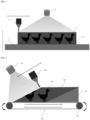
- FIG. 1 such SLA 3D printing technology according to the related art forms a printed matter layer through a process of applying a photocurable ink composition layer by layer onto a build platform 10 through a slot die coater 20 or the like, and selectively curing the applied ink composition through a light emitting unit 30 or the like, and repeatedly performs the layer printing process of applying the ink composition and curing the applied ink composition by emitting light, while vertically moving the build platform, thereby producing a 3D printed matter 50 through stacked printed matter layers 40.
- This printing method is referred to as a batch-type printing method.
- the batch-type 3D printing method arranges the printed matter on a virtual 3D block, having an area to which the printed matter is applied and a height at which the printed matter layers are stacked on the surface of the build platform, slices the printed matter into a plurality of layers, derives a light emitting pattern for each of the layers, and then repeatedly performs a process of applying the ink composition layer by layer according to the derived light emitting pattern and curing the ink composition through light emission, until the height of the layers reach a predetermined height, thereby producing a 3D printed matter.
- such a batch-type 3D printing method has problems in that a printed matter cannot be changed during one batch of printing process once the batch of printing process is started, and printing can be started only after the above-described 3D virtual block is filled with sufficient printed matters to raise the efficiency of printing facilities.
- the batch-type 3D printing method inevitably requires a down time for printing facilities attributable to post processing. For example, after one batch of printing process is ended, the printed matter needs to be collected, and the build platform needs to be reorganized. Therefore, the entire producing speed of a 3D printed product may be delayed, and the batch-type 3D printing method may have many limitations in terms of the diversity of printed matters handled thereby.
- the document US 2017/305139 A1 relates to a method for producing three-dimensional components from individual layers, in which thin layers of amorphous build material, such as particulate material or spreadable pastes, is applied repeatedly and then selectively solidified to form a component cross section.
- amorphous build material such as particulate material or spreadable pastes
- a printed matter block stacked on the conveyor belt is transferred in one direction by the conveyor belt, according to the pace of the printing process, such that a printing space for a subsequent layer can be continuously secured through the transfer of the printed matter block.
- the 3D printing method can continuously output printed matters without a separate additional process such as a replacement operation of the build platform, and simultaneously change the shape of an output printed matter at any time through a simple operation of changing the light pattern emitted by the light emitting unit, during the printing process, thereby significantly improving the efficiency of the printing operation and the diversity of printed matters.
- a 3D printing method is provided using a photocurable ink composition which exists as liquid at a predetermined phase-change temperature or higher, but hardens to a solid at a low temperature equal to or lower than the phase-change temperature.
- the 3D printing method includes: installing a build platform on one side of the top of a conveyor belt which is driven in one direction through a pulley, such that the build platform is inclined at a predetermined angle with the top surface of the conveyor belt; applying a photocurable ink composition layer by layer onto the top surface of the inclined build platform; selectively curing the applied photocurable ink composition layer by emitting a light pattern onto the ink composition layer through a light emitting unit; producing a 3D printed matter through printed matter layers which are repeatedly stacked in a direction indicated at the predetermined angle with the top surface of the conveyor belt, by repeated performing the steps of applying the photocurable ink composition layer by layer onto the ink composition layer onto which the light pattern has been completely emitted, and selectively curing the applied photocur
- the curing process through the application of the ink composition and the light emission is performed in a low temperature chamber which is maintained at a low temperature equal to or lower than the phase change temperature of the ink composition, the conveyor belt is driven in the one direction according to the progress speed of the printing process, and transfer a printed matter block stacked thereon in the one direction, and a printing space for a subsequent layer is continuously secured by the transfer of the printed matter block through the conveyor belt.
- the continuous production-type 3D printing method in accordance with the present disclosure may continuously secure a printing space for a subsequent layer by transferring a printed matter block during a printing process, and remove a down time for printing facilities, required for build platform rearrangement or equipment replacement, thereby producing continuous printed matters without stopping the printing facilities. Therefore, the continuous production-type 3D printing method may raise the productivity of a 3D printed matter, and continuously output various printed matters through one production line, thereby improving the diversity of the produced printed matters.
- FIG. 2 is a diagram for describing the principle of a continuous production-type 3D printing method in accordance with an embodiment of the present disclosure.
- the 3D printing method in accordance with the embodiment of the present disclosure includes installing a build platform 300 on one side of the top surface of a conveyor belt 200 which is made of a metallic material and driven in one direction through a pulley 100, such that the build platform is inclined at a predetermined angle with the top surface of the conveyor belt 200, applying a photocurable ink composition layer by layer onto the top surface of the build platform through a slot die coater 400, and selectively curing the applied photocurable ink composition by emitting a light pattern onto the photocurable ink composition through a light emitting unit 500, thereby forming a printed matter layer along the surface of the build platform 300, such that the printed matter layer is inclined at the predetermined angle with the top surface of the conveyor belt 200.
- the process of applying the photocurable ink composition layer by layer onto the printed matter layer, which is inclined at the predetermined angle with the top surface of the conveyor belt, through the slot die coater 400, and selectively curing the applied photocurable ink composition by emitting the light pattern onto the photocurable ink composition through the light emitting unit 500 is repeatedly performed to form printed matter layers 600 which are repeatedly stacked in such a direction that is diagonal at the predetermined angle with the top surface of the conveyor belt, and a 3D printed matter 700 is produced through the printed matter layers 600.
- the printed matter block stacked on the conveyor belt may be transferred in one direction by the conveyor belt which is driven in the one direction according to the pace of the printing process, which makes it possible to easily and continuously secure the printing space for a subsequent layer.
- the conveyor belt may be configured to be driven whenever the printing process for each layer is completed, or driven once in each printing period in which a plurality of layers with a preset thickness are printed.
- the printing space for a subsequent layer is continuously secured by transferring the printed matter block through the conveyor belt, it is possible to continuously manufacture 3D printed matters without a separate limitation, while the printing facilities are not stopped. Furthermore, it is possible to minimize the operation efficiency of the printing facilities, and to freely change the shape of the printed matter at any time during the printing process for a printed matter through a simple operation of changing the light pattern emitted by the light emitting unit, thereby significantly improving the efficiency of the printing operation and the diversity of printed matters.
- a photocurable resin composition which is cured by emitting a specific wavelength of light including ultraviolet light UV is used as the ink composition for 3D printing.
- the ink composition used in the present disclosure has liquidus viscosity at a predetermined temperature or higher, such that one printed matter layer for 3D printing can be deposited on the surface of a printing plate such as the build platform.
- the ink composition stays in a low temperature state below a predetermined temperature range of phase change temperature zone ⁇ T, the ink composition hardens to a solid while the viscosity thereof rapidly increases.
- FIG. 3 is a graph illustrating a temperature-dependent change in viscosity of the photocurable ink composition used for the continuous production-type 3D printing method in accordance with the present disclosure.
- the ink composition used in the present disclosure exists as liquid having a viscosity of about 1,000,000 cPs or less at a room temperature of about 20°C.
- the viscosity of the ink composition rapidly increases to 10,000,000 cPs or more.
- the viscosity of the ink composition increases to 1,000,000,000 cPs or more, such that the phase of the ink composition changes to a solid state.
- the ink composition having a low-temperature phase change characteristic may be a resin composition which is composed of a monomer having a photocurable (meta)acrylic group with a molecular weight of 50 to 1,000 and an oligomer having a photocurable (meta)acrylic group with a molecular weight of 500 to 1,000,000, and can be photo-cured by a radical method, a resin composition which is composed of a monomer having a photocurable epoxy group with a molecular weight of 50 to 1,000 and an oligomer having a photocurable epoxy group with a molecular weight of 500 to 1,000,000, and can be photo-cured by a cationic method, or a hybrid composition obtained by combining the two resin compositions.
- the process for 3D printing uses such phase-change temperature characteristics of the ink composition and is performed in a low-temperature chamber which is maintained at the environment of a low temperature ranging from 0°C to 10°C, which is equal to or lower than the phase-change temperature of the ink composition. This process will be described below in detail with reference to FIG. 4 .
- the liquid ink composition which is applied layer by layer onto the printing area by the slot die coater is rapidly cooled and changed to a solid state, such that the fluidity thereof is removed. Furthermore, the printed matter block which has hardened but is not cured supports the 3D printed matter cured through light emission, and simultaneously form the printed surface of the ink composition layer which is subsequently applied. Therefore, even after the build platform which has initially formed the printed surface gets out of the printing space with the progress of the printing process, the continuous printing process is maintained through the inclined surface of an uncured printed matter block which is successively stacked in the printing space, by the conveyor belt driven in the one direction.
- FIG. 4 is a diagram for more concretely describing a process in which the continuous production-type 3D printing method in accordance with the embodiment of the present disclosure is implemented through printing facilities.
- the printing process for a printed matter in the 3D printing method in accordance with the present disclosure is performed in a low temperature chamber 800 which is maintained at a low temperature equal to or lower than the phase change temperature of the ink composition.
- the low temperature chamber 800 may include a temperature control unit (not illustrated) such as a cooler to maintain the internal atmosphere at a predetermined temperature or lower at all times.
- the 3D printing method in accordance with the embodiment of the present disclosure includes providing the conveyor belt 200 which is made of a metallic material and driven in one direction through the pulley 100, installing the build platform 300 (see FIG. 2 ), which is inclined at a predetermined angle with the top surface of the conveyor belt 200, on one side of the top surface of the conveyor belt 200, applying a liquid photocurable ink composition layer by layer onto the top surface of the build platform through the slot die coater 400, and selectively curing the applied photocurable ink composition by emitting a light pattern thereto through the light emitting unit 500, thereby forming a printed matter layer along the surface of the build platform 300, such that the printed matter layer is inclined at the predetermined angle with the top surface of the conveyor belt 200.
- a cooling unit such as a cooling loop may be connected to the above-described conveyor belt 200 or the build platform, such that the surface temperature of the conveyor belt and the build platform can be always maintained at a predetermined temperature or lower.
- the inclination angle of the build platform 300 may be properly set according to the characteristic of the ink composition and the size of the 3D printed matter as a printing target. Desirably, it is effective to set the inclination angle to an angle of 10° to 60° with respect to the top surface of the conveyor belt.
- the process of applying the photocurable ink composition layer by layer onto the printed matter layer, which is inclined at the predetermined angle with the top surface of the conveyor belt, through the slot die coater 400, and selectively curing the applied photocurable ink composition by emitting the light pattern onto the photocurable ink composition through the light emitting unit 500 is repeatedly performed to form the printed matter layers 600 which are repeatedly stacked in such a direction that is diagonal at the predetermined angle with the top surface of the conveyor belt, and the 3D printed matter 700 is produced through the printed matter layers 600.
- the printed matter block stacked on the conveyor belt 200 is transferred in one direction by the conveyor belt 200 which is driven in the one direction, according to the pace of the printing process, which makes it possible to easily and continuously secure a printing space for a subsequent layer.
- the conveyor belt may be configured to be driven whenever the printing process for each layer is completed, or driven once in each printing period in which a plurality of layers with a preset thickness are printed.
- a separation collection room 900 is connected to one outer wall of the low temperature chamber 800 to which the printed matter block is transferred by the conveyor belt 200, and serves to separate and collect the 3D printed matter 700 from the transferred printed matter block, and collect and reuse the ink composition, which has hardened but is not cured, by reducing the ink composition into liquid in the low temperature chamber 800.
- the operation environment of the separation collection room is maintained at a temperature higher than the phase-change temperature of the ink composition.
- the phase of the uncured ink composition constituting the transferred printed matter block changes to a liquid state again.
- the conveyor belt 200 for transferring the printed matter block may be extended up to the separation collection room 900, and a separate temperature control unit (not illustrated) may be installed in the separation collection room 900 to maintain the internal atmosphere at the predetermined temperature or higher at all times. Furthermore, the extended portion of the conveyor belt formed in such a manner may also include a separate temperature control unit (not illustrated) to maintain the same temperature condition as the inside of the separation collection room 900.
- a transfer path 910 is formed to transfer the printed matter block.
- a heat insulating unit such as an air curtain or curtain wall may be installed to prevent heat exchange caused by a temperature difference between the two spaces.
- the ink composition which is not cured and constitutes the transferred printed matter block is changed again to liquid by the operation environment of the separation collection room 900, and naturally separated from the 3D printed matter cured in the printing process.
- the cured 3D printed matter may be separated and collected while the continuous 3D printing process is performed without stopping the printing process to separate the 3D printed matter.
- the liquid ink composition may be collected into an ink collection tub 920 installed under the conveyor belt 200 extended into the separation collection room 900, and then reused.
- the uncured ink composition constituting the transferred printed matter block may be changed again to liquid in the separation collection room 900, and collected by the ink collection tub 920 installed under the conveyor belt 200.
- the ink composition collected through the ink collection tub 920 may be filtered by a filter 940 through a collection line 930, transferred to an ink storage bath 950 in which the ink composition supplied to the slot die coater 400 is stored, and then supplied to the slot die coater 400 through a supply line 960 again.
- the ink composition which is not cured during the printing process may not be wasted, but be effectively reused.
- the uncured ink composition remaining on the surface of the 3D printed matter 700 separated from the phase-changed ink composition is completely removed through a cleaning process using a cleaning solution, and the 3D printed matter 700 is then dried and completely produced.
- the above-described operation environment of the separation collection room or the environment for the storage, collection and storage lines of the ink composition may be set to a room temperature environment, on the basis of the characteristic of the ink composition which hardens to a solid matter at a predetermined temperature or lower, but changes again to liquid at room temperature.
- post-processing operations such as a cleaning process for the collected 3D printed matter may be all performed at room temperature, which makes it possible to easily construct the printing and post-processing facilities based on overall processes required for the 3D printing, and to maximize the convenience and efficiency of the processing operation.
- the continuous production-type 3D printing method in accordance with the present disclosure includes repeatedly performing the printing process of installing the build platform on the conveyor belt made of a metallic material, such that the built platform is inclined at the predetermined angle with the top surface of the conveyor belt, applying the photocurable ink composition layer by layer onto the top surface of the build platform, and selectively curing the applied photocurable ink composition by emitting a light pattern thereto through the light emitting unit.
- the printed matter block stacked on the conveyer block may be transferred in one direction by the conveyor belt, according to the pace of the printing process, such that the printing space for a subsequent layer can be continuously secured through the transfer of the printed matter block.
- the 3D printing method can continuously output printed matters without a separate additional process such as a replacement operation of the build platform, and simultaneously change the shape of an output printed matter at any time through a simple operation of changing the light pattern emitted by the light emitting unit, during the printing process, thereby significantly improving the efficiency of the printing operation and the diversity of printed matters.
- the operation environment of the separation collection room for collecting the 3D printed matter, the collection and supply lines of the ink composition, and post-processing operations such as a cleaning operation of the collected 3D printed matter may be all performed at room temperature.
- the printing and post-processing facilities of the overall processes required for 3D printing may be easily constructed, which makes it possible to maximize the convenience and efficiency of the processing operations.
Landscapes
- Engineering & Computer Science (AREA)
- Materials Engineering (AREA)
- Chemical & Material Sciences (AREA)
- Manufacturing & Machinery (AREA)
- Optics & Photonics (AREA)
- Mechanical Engineering (AREA)
- Physics & Mathematics (AREA)
- Robotics (AREA)
- Life Sciences & Earth Sciences (AREA)
- Sustainable Development (AREA)
- Health & Medical Sciences (AREA)
- Environmental & Geological Engineering (AREA)
- Toxicology (AREA)
Claims (11)
- Procédé d'impression 3D utilisant une composition d'encre photodurcissable qui existe sous forme de liquide à une température de changement de phase prédéterminée ou plus élevée, mais qui durcit en une matière solide à une basse température égale ou inférieure à la température de changement de phase, le procédé d'impression 3D comprenant de :installer une plate-forme de construction (300) sur un côté du niveau supérieur d'une bande transporteuse (200) qui est entraînée dans une direction par une poulie, de telle sorte que la plate-forme de construction soit inclinée à un angle prédéterminé par rapport à la surface supérieure de la bande transporteuse (200) ;appliquer une composition d'encre photodurcissable couche par couche sur la surface supérieure de la plate-forme de construction inclinée ;durcir sélectivement la couche de composition d'encre photodurcissable appliquée en émettant un motif lumineux sur la couche de composition d'encre par une unité d'émission de lumière (500) ;produire une matière imprimée en 3D au moyen de couches de matière imprimée qui sont empilées de manière répétée dans une direction indiquée à l'angle prédéterminé avec la surface supérieure de la bande transporteuse (200), en effectuant de manière répétée les étapes d'appliquer la composition d'encre photodurcissable couche par couche sur la couche de composition d'encre sur laquelle le motif lumineux a été complètement émis, et de durcir sélectivement la couche de composition d'encre photodurcissable appliquée en émettant le motif lumineux sur la couche de composition d'encre par l'unité d'émission de lumière (500),dans lequel le processus de durcissement par l'application de la composition d'encre et l'émission de lumière est effectué dans une chambre à basse température (800) qui est maintenue à une basse température égale ou inférieure à la température de changement de phase de la composition d'encre,la bande transporteuse (200) est entraînée dans ladite direction en fonction de la vitesse d'avancement du processus d'impression, et transfère un bloc de matière imprimée empilé dessus dans ladite direction, etun espace d'impression pour une couche suivante est continuellement assuré par le transfert du bloc de matière imprimée par la bande transporteuse (200).
- Procédé d'impression 3D selon la revendication 1, dans lequel la plate-forme de construction est formée à un angle de 10° à 60° par rapport à la surface supérieure de la bande transporteuse.
- Procédé d'impression 3D selon la revendication 1, dans lequel la bande transporteuse est configurée pour être entraînée chaque fois que le processus d'impression de chaque couche est terminé, ou pour être entraînée une fois dans chaque période d'impression au cours de laquelle une pluralité de couches d'une épaisseur prédéfinie sont imprimées.
- Procédé d'impression 3D selon la revendication 1, dans lequel une enceinte de séparation et collecte pour séparer et collecter la matière imprimée en 3D du bloc de matière imprimée transféré est reliée à une paroi extérieure de la chambre à basse température dans laquelle le bloc de matière imprimée est transféré par la courroie transporteuse, et un chemin de transfert pour transférer le bloc de matière imprimée est formé au niveau de la paroi de délimitation entre la chambre à basse température et l'enceinte de séparation et collecte, et la bande transporteuse est prolongée dans l'enceinte de séparation et collecte pour transférer le bloc de matière imprimée, de sorte que la matière imprimée en 3D produite est collectée dans l'enceinte de séparation et collecte.
- Procédé d'impression 3D selon la revendication 4, dans lequel l'enceinte de séparation et collecte est maintenue à une température supérieure à la température de changement de phase de la composition d'encre.
- Procédé d'impression 3D selon la revendication 5, dans lequel le chemin de transfert inclut une unité d'isolation thermique configurée comme un rideau d'air ou un mur-rideau pour supprimer l'échange de chaleur causé par une différence de température entre la chambre à basse température et l'enceinte de séparation et collecte.
- Procédé d'impression 3D selon la revendication 5, dans lequel un bac de collecte d'encre pour collecter la composition d'encre est installé sous la bande transporteuse prolongée jusqu'à l'enceinte de séparation et collecte,
dans lequel la composition d'encre non durcie, qui est incluse dans le bloc de matière imprimée transféré dans l'enceinte de séparation et collecte, redevenue liquide dans l'enceinte de séparation et collecte et séparée de la matière imprimée en 3D, est collectée et réutilisée. - Procédé d'impression 3D selon la revendication 7, dans lequel la composition d'encre collectée par le bac de collecte d'encre est filtrée à travers un filtre et ensuite réutilisée.
- Procédé d'impression 3D selon la revendication 1, dans lequel la chambre à basse température est maintenue à une basse température de 0 °C à 10 °C.
- Procédé d'impression 3D selon la revendication 5, dans lequel l'enceinte de séparation et collecte est utilisée dans un environnement à température ambiante.
- Procédé d'impression 3D selon la revendication 4, comprenant en outre d'éliminer complètement la composition d'encre non durcie restant sur la surface de la matière imprimée à l'aide d'une solution de nettoyage après que la matière imprimée en 3D a été collectée à partir de l'enceinte de séparation et collecte.
Applications Claiming Priority (2)
| Application Number | Priority Date | Filing Date | Title |
|---|---|---|---|
| KR1020190179633A KR102292615B1 (ko) | 2019-12-31 | 2019-12-31 | 연속 생산 방식의 3d 프린팅 방법 |
| PCT/KR2020/017450 WO2021137451A1 (fr) | 2019-12-31 | 2020-12-02 | Procédé d'impression 3d de type à production continue |
Publications (3)
| Publication Number | Publication Date |
|---|---|
| EP3936306A1 EP3936306A1 (fr) | 2022-01-12 |
| EP3936306A4 EP3936306A4 (fr) | 2022-11-23 |
| EP3936306B1 true EP3936306B1 (fr) | 2024-02-07 |
Family
ID=76685897
Family Applications (1)
| Application Number | Title | Priority Date | Filing Date |
|---|---|---|---|
| EP20909566.0A Active EP3936306B1 (fr) | 2019-12-31 | 2020-12-02 | Procédé d'impression 3d de type à production continue |
Country Status (4)
| Country | Link |
|---|---|
| US (1) | US20220184894A1 (fr) |
| EP (1) | EP3936306B1 (fr) |
| KR (1) | KR102292615B1 (fr) |
| WO (1) | WO2021137451A1 (fr) |
Families Citing this family (3)
| Publication number | Priority date | Publication date | Assignee | Title |
|---|---|---|---|---|
| US12240174B2 (en) | 2022-11-21 | 2025-03-04 | International Business Machines Corporation | Continuous 3D printing |
| KR20250060125A (ko) * | 2023-10-25 | 2025-05-07 | 주식회사 알데바 | 하이드로겔 조성물 및 이를 이용한 과립형 하이드로겔의 제조방법 |
| EP4559679A1 (fr) * | 2023-11-22 | 2025-05-28 | Insolution Group B.V. | Dispositif d'impression tridimensionnelle |
Family Cites Families (15)
| Publication number | Priority date | Publication date | Assignee | Title |
|---|---|---|---|---|
| US5248456A (en) * | 1989-06-12 | 1993-09-28 | 3D Systems, Inc. | Method and apparatus for cleaning stereolithographically produced objects |
| DE102010015451A1 (de) * | 2010-04-17 | 2011-10-20 | Voxeljet Technology Gmbh | Verfahren und Vorrichtung zum Herstellen dreidimensionaler Objekte |
| DE102012010272A1 (de) * | 2012-05-25 | 2013-11-28 | Voxeljet Technology Gmbh | Verfahren zum Herstellen dreidimensionaler Modelle mit speziellen Bauplattformen und Antriebssystemen |
| DE102012022859A1 (de) * | 2012-11-25 | 2014-05-28 | Voxeljet Ag | Aufbau eines 3D-Druckgerätes zur Herstellung von Bauteilen |
| WO2015190168A1 (fr) * | 2014-06-11 | 2015-12-17 | コニカミノルタ株式会社 | Appareil de fabrication en trois dimensions et procédé de fabrication en trois dimensions |
| DE102014014895A1 (de) * | 2014-10-13 | 2016-04-14 | Voxeljet Ag | Verfahren und Vorrichtung zur Herstellung von Bauteilen in einem Schichtbauverfahren |
| JP6776056B2 (ja) * | 2015-08-31 | 2020-10-28 | キヤノン株式会社 | 造形装置及び造形方法 |
| US10174205B2 (en) * | 2015-10-19 | 2019-01-08 | Xerox Corporation | Printing process |
| KR101821772B1 (ko) * | 2015-11-16 | 2018-01-24 | 이병극 | 3d 조형물의 후처리 장치 |
| KR102125596B1 (ko) * | 2016-04-08 | 2020-06-22 | 주식회사 엘지화학 | 3d 프린팅 지지체용 잉크 조성물 |
| DE102016219037A1 (de) * | 2016-09-30 | 2018-04-05 | Ford Global Technologies, Llc | Additives Fertigungsverfahren |
| US20190126536A1 (en) * | 2017-11-02 | 2019-05-02 | General Electric Company | Cartridge vat-based additive manufacturing apparatus and method |
| WO2019144896A1 (fr) * | 2018-01-25 | 2019-08-01 | 广州迈普再生医学科技股份有限公司 | Tête de pulvérisation piézoélectrique d'imprimante 3d et sa méthode de fonctionnement, et imprimante 3d |
| KR102026990B1 (ko) | 2018-06-11 | 2019-09-30 | 주식회사 힉스 | Sla 3d 프린터 |
| US20190375014A1 (en) * | 2018-06-11 | 2019-12-12 | Desktop Metal, Inc. | Shrinking interface layers |
-
2019
- 2019-12-31 KR KR1020190179633A patent/KR102292615B1/ko active Active
-
2020
- 2020-12-02 WO PCT/KR2020/017450 patent/WO2021137451A1/fr not_active Ceased
- 2020-12-02 EP EP20909566.0A patent/EP3936306B1/fr active Active
- 2020-12-02 US US17/594,222 patent/US20220184894A1/en not_active Abandoned
Also Published As
| Publication number | Publication date |
|---|---|
| KR20210085996A (ko) | 2021-07-08 |
| EP3936306A1 (fr) | 2022-01-12 |
| WO2021137451A1 (fr) | 2021-07-08 |
| US20220184894A1 (en) | 2022-06-16 |
| EP3936306A4 (fr) | 2022-11-23 |
| KR102292615B1 (ko) | 2021-08-24 |
Similar Documents
| Publication | Publication Date | Title |
|---|---|---|
| EP3936306B1 (fr) | Procédé d'impression 3d de type à production continue | |
| TWI601626B (zh) | 藉由層疊製造製出有形產品之方法及設備 | |
| EP3708337B1 (fr) | Procédé et appareil de fabrication additive comportant des composants partagés | |
| TW201600322A (zh) | 用以藉由分層製造技術製作有形產品之方法及生產線 | |
| EP2447045B1 (fr) | Procédé de formage tridimensionnel et appareil de formage tridimensionnel | |
| CN102905876B (zh) | 一种制作三维模型的方法和装置 | |
| US10421265B2 (en) | Apparatus and method for making tangible products by layerwise manufacturing | |
| WO2003028985B1 (fr) | Modelisation par depot selectif avec des materiaux a changement de phase durcissables | |
| RU2018109736A (ru) | Система и аппаратный агрегат трехмерной печати | |
| US10987868B2 (en) | Production line for making tangible products by layerwise manufacturing | |
| US20120211155A1 (en) | Device and Method for Generative Production | |
| JP7610678B2 (ja) | 部材の付加製造用の3dプリンタおよび印刷方法 | |
| JP2017507227A (ja) | 多層研磨粒子の製造方法 | |
| KR102909291B1 (ko) | 부품의 생성 제조 시스템 및 방법 | |
| JP7200225B2 (ja) | 選択的液体冷却による付加製造 | |
| JP7514238B2 (ja) | 脱バインダと焼結中の部品の支持体 | |
| CN107053668B (zh) | 一种纤维复合材料的制备方法及其专用设备 | |
| US10562211B2 (en) | System for removing support structure from three-dimensional printed objects using microwave energy | |
| FI126800B (en) | Method for casting concrete products | |
| CN106696273A (zh) | 用于利用微波能从三维打印物体去除支承结构的系统和方法 | |
| US20190314931A1 (en) | Apparatus for producing an object by means of additive manufacturing and method of using the apparatus | |
| RU2785968C2 (ru) | Аддитивное производство посредством селективного охлаждения жидкости | |
| KR101504073B1 (ko) | 박막적층 방식 및 경화성 물질을 이용하는 3d 프린팅 방법 | |
| JP2019123223A (ja) | 3次元印刷システム | |
| TW201716215A (zh) | 積層製造方法 |
Legal Events
| Date | Code | Title | Description |
|---|---|---|---|
| STAA | Information on the status of an ep patent application or granted ep patent |
Free format text: STATUS: THE INTERNATIONAL PUBLICATION HAS BEEN MADE |
|
| PUAI | Public reference made under article 153(3) epc to a published international application that has entered the european phase |
Free format text: ORIGINAL CODE: 0009012 |
|
| STAA | Information on the status of an ep patent application or granted ep patent |
Free format text: STATUS: REQUEST FOR EXAMINATION WAS MADE |
|
| 17P | Request for examination filed |
Effective date: 20211005 |
|
| AK | Designated contracting states |
Kind code of ref document: A1 Designated state(s): AL AT BE BG CH CY CZ DE DK EE ES FI FR GB GR HR HU IE IS IT LI LT LU LV MC MK MT NL NO PL PT RO RS SE SI SK SM TR |
|
| REG | Reference to a national code |
Ref country code: DE Free format text: PREVIOUS MAIN CLASS: B29C0064100000 Ipc: B29C0064124000 Ref legal event code: R079 Ref document number: 602020025481 Country of ref document: DE |
|
| A4 | Supplementary search report drawn up and despatched |
Effective date: 20221020 |
|
| RIC1 | Information provided on ipc code assigned before grant |
Ipc: B29C 64/364 20170101ALI20221014BHEP Ipc: B33Y 70/00 20200101ALI20221014BHEP Ipc: B33Y 40/20 20200101ALI20221014BHEP Ipc: B33Y 30/00 20150101ALI20221014BHEP Ipc: B33Y 10/00 20150101ALI20221014BHEP Ipc: B29C 64/379 20170101ALI20221014BHEP Ipc: B29C 64/357 20170101ALI20221014BHEP Ipc: B29C 64/245 20170101ALI20221014BHEP Ipc: B29C 64/10 20170101ALI20221014BHEP Ipc: B29C 64/124 20170101AFI20221014BHEP |
|
| DAV | Request for validation of the european patent (deleted) | ||
| DAX | Request for extension of the european patent (deleted) | ||
| GRAP | Despatch of communication of intention to grant a patent |
Free format text: ORIGINAL CODE: EPIDOSNIGR1 |
|
| STAA | Information on the status of an ep patent application or granted ep patent |
Free format text: STATUS: GRANT OF PATENT IS INTENDED |
|
| INTG | Intention to grant announced |
Effective date: 20230706 |
|
| GRAS | Grant fee paid |
Free format text: ORIGINAL CODE: EPIDOSNIGR3 |
|
| GRAA | (expected) grant |
Free format text: ORIGINAL CODE: 0009210 |
|
| STAA | Information on the status of an ep patent application or granted ep patent |
Free format text: STATUS: THE PATENT HAS BEEN GRANTED |
|
| AK | Designated contracting states |
Kind code of ref document: B1 Designated state(s): AL AT BE BG CH CY CZ DE DK EE ES FI FR GB GR HR HU IE IS IT LI LT LU LV MC MK MT NL NO PL PT RO RS SE SI SK SM TR |
|
| REG | Reference to a national code |
Ref country code: GB Ref legal event code: FG4D |
|
| REG | Reference to a national code |
Ref country code: CH Ref legal event code: EP |
|
| REG | Reference to a national code |
Ref country code: IE Ref legal event code: FG4D |
|
| REG | Reference to a national code |
Ref country code: DE Ref legal event code: R096 Ref document number: 602020025481 Country of ref document: DE |
|
| REG | Reference to a national code |
Ref country code: LT Ref legal event code: MG9D |
|
| REG | Reference to a national code |
Ref country code: NL Ref legal event code: MP Effective date: 20240207 |
|
| PG25 | Lapsed in a contracting state [announced via postgrant information from national office to epo] |
Ref country code: IS Free format text: LAPSE BECAUSE OF FAILURE TO SUBMIT A TRANSLATION OF THE DESCRIPTION OR TO PAY THE FEE WITHIN THE PRESCRIBED TIME-LIMIT Effective date: 20240607 |
|
| PG25 | Lapsed in a contracting state [announced via postgrant information from national office to epo] |
Ref country code: LT Free format text: LAPSE BECAUSE OF FAILURE TO SUBMIT A TRANSLATION OF THE DESCRIPTION OR TO PAY THE FEE WITHIN THE PRESCRIBED TIME-LIMIT Effective date: 20240207 |
|
| PG25 | Lapsed in a contracting state [announced via postgrant information from national office to epo] |
Ref country code: GR Free format text: LAPSE BECAUSE OF FAILURE TO SUBMIT A TRANSLATION OF THE DESCRIPTION OR TO PAY THE FEE WITHIN THE PRESCRIBED TIME-LIMIT Effective date: 20240508 |
|
| REG | Reference to a national code |
Ref country code: AT Ref legal event code: MK05 Ref document number: 1655104 Country of ref document: AT Kind code of ref document: T Effective date: 20240207 |
|
| PG25 | Lapsed in a contracting state [announced via postgrant information from national office to epo] |
Ref country code: RS Free format text: LAPSE BECAUSE OF FAILURE TO SUBMIT A TRANSLATION OF THE DESCRIPTION OR TO PAY THE FEE WITHIN THE PRESCRIBED TIME-LIMIT Effective date: 20240507 Ref country code: HR Free format text: LAPSE BECAUSE OF FAILURE TO SUBMIT A TRANSLATION OF THE DESCRIPTION OR TO PAY THE FEE WITHIN THE PRESCRIBED TIME-LIMIT Effective date: 20240207 Ref country code: NL Free format text: LAPSE BECAUSE OF FAILURE TO SUBMIT A TRANSLATION OF THE DESCRIPTION OR TO PAY THE FEE WITHIN THE PRESCRIBED TIME-LIMIT Effective date: 20240207 |
|
| PG25 | Lapsed in a contracting state [announced via postgrant information from national office to epo] |
Ref country code: ES Free format text: LAPSE BECAUSE OF FAILURE TO SUBMIT A TRANSLATION OF THE DESCRIPTION OR TO PAY THE FEE WITHIN THE PRESCRIBED TIME-LIMIT Effective date: 20240207 |
|
| PG25 | Lapsed in a contracting state [announced via postgrant information from national office to epo] |
Ref country code: AT Free format text: LAPSE BECAUSE OF FAILURE TO SUBMIT A TRANSLATION OF THE DESCRIPTION OR TO PAY THE FEE WITHIN THE PRESCRIBED TIME-LIMIT Effective date: 20240207 |
|
| PG25 | Lapsed in a contracting state [announced via postgrant information from national office to epo] |
Ref country code: RS Free format text: LAPSE BECAUSE OF FAILURE TO SUBMIT A TRANSLATION OF THE DESCRIPTION OR TO PAY THE FEE WITHIN THE PRESCRIBED TIME-LIMIT Effective date: 20240507 Ref country code: NO Free format text: LAPSE BECAUSE OF FAILURE TO SUBMIT A TRANSLATION OF THE DESCRIPTION OR TO PAY THE FEE WITHIN THE PRESCRIBED TIME-LIMIT Effective date: 20240507 Ref country code: NL Free format text: LAPSE BECAUSE OF FAILURE TO SUBMIT A TRANSLATION OF THE DESCRIPTION OR TO PAY THE FEE WITHIN THE PRESCRIBED TIME-LIMIT Effective date: 20240207 Ref country code: LT Free format text: LAPSE BECAUSE OF FAILURE TO SUBMIT A TRANSLATION OF THE DESCRIPTION OR TO PAY THE FEE WITHIN THE PRESCRIBED TIME-LIMIT Effective date: 20240207 Ref country code: IS Free format text: LAPSE BECAUSE OF FAILURE TO SUBMIT A TRANSLATION OF THE DESCRIPTION OR TO PAY THE FEE WITHIN THE PRESCRIBED TIME-LIMIT Effective date: 20240607 Ref country code: HR Free format text: LAPSE BECAUSE OF FAILURE TO SUBMIT A TRANSLATION OF THE DESCRIPTION OR TO PAY THE FEE WITHIN THE PRESCRIBED TIME-LIMIT Effective date: 20240207 Ref country code: GR Free format text: LAPSE BECAUSE OF FAILURE TO SUBMIT A TRANSLATION OF THE DESCRIPTION OR TO PAY THE FEE WITHIN THE PRESCRIBED TIME-LIMIT Effective date: 20240508 Ref country code: FI Free format text: LAPSE BECAUSE OF FAILURE TO SUBMIT A TRANSLATION OF THE DESCRIPTION OR TO PAY THE FEE WITHIN THE PRESCRIBED TIME-LIMIT Effective date: 20240207 Ref country code: ES Free format text: LAPSE BECAUSE OF FAILURE TO SUBMIT A TRANSLATION OF THE DESCRIPTION OR TO PAY THE FEE WITHIN THE PRESCRIBED TIME-LIMIT Effective date: 20240207 Ref country code: BG Free format text: LAPSE BECAUSE OF FAILURE TO SUBMIT A TRANSLATION OF THE DESCRIPTION OR TO PAY THE FEE WITHIN THE PRESCRIBED TIME-LIMIT Effective date: 20240207 Ref country code: AT Free format text: LAPSE BECAUSE OF FAILURE TO SUBMIT A TRANSLATION OF THE DESCRIPTION OR TO PAY THE FEE WITHIN THE PRESCRIBED TIME-LIMIT Effective date: 20240207 |
|
| PG25 | Lapsed in a contracting state [announced via postgrant information from national office to epo] |
Ref country code: PT Free format text: LAPSE BECAUSE OF FAILURE TO SUBMIT A TRANSLATION OF THE DESCRIPTION OR TO PAY THE FEE WITHIN THE PRESCRIBED TIME-LIMIT Effective date: 20240607 Ref country code: PL Free format text: LAPSE BECAUSE OF FAILURE TO SUBMIT A TRANSLATION OF THE DESCRIPTION OR TO PAY THE FEE WITHIN THE PRESCRIBED TIME-LIMIT Effective date: 20240207 |
|
| PG25 | Lapsed in a contracting state [announced via postgrant information from national office to epo] |
Ref country code: SE Free format text: LAPSE BECAUSE OF FAILURE TO SUBMIT A TRANSLATION OF THE DESCRIPTION OR TO PAY THE FEE WITHIN THE PRESCRIBED TIME-LIMIT Effective date: 20240207 Ref country code: PT Free format text: LAPSE BECAUSE OF FAILURE TO SUBMIT A TRANSLATION OF THE DESCRIPTION OR TO PAY THE FEE WITHIN THE PRESCRIBED TIME-LIMIT Effective date: 20240607 Ref country code: PL Free format text: LAPSE BECAUSE OF FAILURE TO SUBMIT A TRANSLATION OF THE DESCRIPTION OR TO PAY THE FEE WITHIN THE PRESCRIBED TIME-LIMIT Effective date: 20240207 Ref country code: LV Free format text: LAPSE BECAUSE OF FAILURE TO SUBMIT A TRANSLATION OF THE DESCRIPTION OR TO PAY THE FEE WITHIN THE PRESCRIBED TIME-LIMIT Effective date: 20240207 |
|
| PG25 | Lapsed in a contracting state [announced via postgrant information from national office to epo] |
Ref country code: DK Free format text: LAPSE BECAUSE OF FAILURE TO SUBMIT A TRANSLATION OF THE DESCRIPTION OR TO PAY THE FEE WITHIN THE PRESCRIBED TIME-LIMIT Effective date: 20240207 |
|
| PG25 | Lapsed in a contracting state [announced via postgrant information from national office to epo] |
Ref country code: SM Free format text: LAPSE BECAUSE OF FAILURE TO SUBMIT A TRANSLATION OF THE DESCRIPTION OR TO PAY THE FEE WITHIN THE PRESCRIBED TIME-LIMIT Effective date: 20240207 |
|
| PG25 | Lapsed in a contracting state [announced via postgrant information from national office to epo] |
Ref country code: CZ Free format text: LAPSE BECAUSE OF FAILURE TO SUBMIT A TRANSLATION OF THE DESCRIPTION OR TO PAY THE FEE WITHIN THE PRESCRIBED TIME-LIMIT Effective date: 20240207 Ref country code: EE Free format text: LAPSE BECAUSE OF FAILURE TO SUBMIT A TRANSLATION OF THE DESCRIPTION OR TO PAY THE FEE WITHIN THE PRESCRIBED TIME-LIMIT Effective date: 20240207 |
|
| PG25 | Lapsed in a contracting state [announced via postgrant information from national office to epo] |
Ref country code: SK Free format text: LAPSE BECAUSE OF FAILURE TO SUBMIT A TRANSLATION OF THE DESCRIPTION OR TO PAY THE FEE WITHIN THE PRESCRIBED TIME-LIMIT Effective date: 20240207 |
|
| PG25 | Lapsed in a contracting state [announced via postgrant information from national office to epo] |
Ref country code: SM Free format text: LAPSE BECAUSE OF FAILURE TO SUBMIT A TRANSLATION OF THE DESCRIPTION OR TO PAY THE FEE WITHIN THE PRESCRIBED TIME-LIMIT Effective date: 20240207 Ref country code: SK Free format text: LAPSE BECAUSE OF FAILURE TO SUBMIT A TRANSLATION OF THE DESCRIPTION OR TO PAY THE FEE WITHIN THE PRESCRIBED TIME-LIMIT Effective date: 20240207 Ref country code: RO Free format text: LAPSE BECAUSE OF FAILURE TO SUBMIT A TRANSLATION OF THE DESCRIPTION OR TO PAY THE FEE WITHIN THE PRESCRIBED TIME-LIMIT Effective date: 20240207 Ref country code: EE Free format text: LAPSE BECAUSE OF FAILURE TO SUBMIT A TRANSLATION OF THE DESCRIPTION OR TO PAY THE FEE WITHIN THE PRESCRIBED TIME-LIMIT Effective date: 20240207 Ref country code: DK Free format text: LAPSE BECAUSE OF FAILURE TO SUBMIT A TRANSLATION OF THE DESCRIPTION OR TO PAY THE FEE WITHIN THE PRESCRIBED TIME-LIMIT Effective date: 20240207 Ref country code: CZ Free format text: LAPSE BECAUSE OF FAILURE TO SUBMIT A TRANSLATION OF THE DESCRIPTION OR TO PAY THE FEE WITHIN THE PRESCRIBED TIME-LIMIT Effective date: 20240207 |
|
| REG | Reference to a national code |
Ref country code: DE Ref legal event code: R097 Ref document number: 602020025481 Country of ref document: DE |
|
| PLBE | No opposition filed within time limit |
Free format text: ORIGINAL CODE: 0009261 |
|
| STAA | Information on the status of an ep patent application or granted ep patent |
Free format text: STATUS: NO OPPOSITION FILED WITHIN TIME LIMIT |
|
| 26N | No opposition filed |
Effective date: 20241108 |
|
| PG25 | Lapsed in a contracting state [announced via postgrant information from national office to epo] |
Ref country code: SI Free format text: LAPSE BECAUSE OF FAILURE TO SUBMIT A TRANSLATION OF THE DESCRIPTION OR TO PAY THE FEE WITHIN THE PRESCRIBED TIME-LIMIT Effective date: 20240207 |
|
| PG25 | Lapsed in a contracting state [announced via postgrant information from national office to epo] |
Ref country code: MC Free format text: LAPSE BECAUSE OF FAILURE TO SUBMIT A TRANSLATION OF THE DESCRIPTION OR TO PAY THE FEE WITHIN THE PRESCRIBED TIME-LIMIT Effective date: 20240207 |
|
| REG | Reference to a national code |
Ref country code: CH Ref legal event code: PL |
|
| PG25 | Lapsed in a contracting state [announced via postgrant information from national office to epo] |
Ref country code: LU Free format text: LAPSE BECAUSE OF NON-PAYMENT OF DUE FEES Effective date: 20241202 |
|
| GBPC | Gb: european patent ceased through non-payment of renewal fee |
Effective date: 20241202 |
|
| REG | Reference to a national code |
Ref country code: BE Ref legal event code: MM Effective date: 20241231 |
|
| PG25 | Lapsed in a contracting state [announced via postgrant information from national office to epo] |
Ref country code: BE Free format text: LAPSE BECAUSE OF NON-PAYMENT OF DUE FEES Effective date: 20241231 Ref country code: GB Free format text: LAPSE BECAUSE OF NON-PAYMENT OF DUE FEES Effective date: 20241202 |
|
| PG25 | Lapsed in a contracting state [announced via postgrant information from national office to epo] |
Ref country code: CH Free format text: LAPSE BECAUSE OF NON-PAYMENT OF DUE FEES Effective date: 20241231 |
|
| PG25 | Lapsed in a contracting state [announced via postgrant information from national office to epo] |
Ref country code: IE Free format text: LAPSE BECAUSE OF NON-PAYMENT OF DUE FEES Effective date: 20241202 |
|
| PGFP | Annual fee paid to national office [announced via postgrant information from national office to epo] |
Ref country code: IT Payment date: 20251223 Year of fee payment: 6 |
|
| PGFP | Annual fee paid to national office [announced via postgrant information from national office to epo] |
Ref country code: FR Payment date: 20251229 Year of fee payment: 6 |
|
| PG25 | Lapsed in a contracting state [announced via postgrant information from national office to epo] |
Ref country code: CY Free format text: LAPSE BECAUSE OF FAILURE TO SUBMIT A TRANSLATION OF THE DESCRIPTION OR TO PAY THE FEE WITHIN THE PRESCRIBED TIME-LIMIT; INVALID AB INITIO Effective date: 20201202 |
|
| PGFP | Annual fee paid to national office [announced via postgrant information from national office to epo] |
Ref country code: DE Payment date: 20251230 Year of fee payment: 6 |