EP3628525B1 - Véhicule automobile doté d'un entraînement auxiliaire pour un essieu dirigeable - Google Patents
Véhicule automobile doté d'un entraînement auxiliaire pour un essieu dirigeable Download PDFInfo
- Publication number
- EP3628525B1 EP3628525B1 EP19199616.4A EP19199616A EP3628525B1 EP 3628525 B1 EP3628525 B1 EP 3628525B1 EP 19199616 A EP19199616 A EP 19199616A EP 3628525 B1 EP3628525 B1 EP 3628525B1
- Authority
- EP
- European Patent Office
- Prior art keywords
- axle
- drive
- differential
- motor
- transmission
- Prior art date
- Legal status (The legal status is an assumption and is not a legal conclusion. Google has not performed a legal analysis and makes no representation as to the accuracy of the status listed.)
- Active
Links
Images


Classifications
-
- B—PERFORMING OPERATIONS; TRANSPORTING
- B60—VEHICLES IN GENERAL
- B60K—ARRANGEMENT OR MOUNTING OF PROPULSION UNITS OR OF TRANSMISSIONS IN VEHICLES; ARRANGEMENT OR MOUNTING OF PLURAL DIVERSE PRIME-MOVERS IN VEHICLES; AUXILIARY DRIVES FOR VEHICLES; INSTRUMENTATION OR DASHBOARDS FOR VEHICLES; ARRANGEMENTS IN CONNECTION WITH COOLING, AIR INTAKE, GAS EXHAUST OR FUEL SUPPLY OF PROPULSION UNITS IN VEHICLES
- B60K17/00—Arrangement or mounting of transmissions in vehicles
- B60K17/34—Arrangement or mounting of transmissions in vehicles for driving both front and rear wheels, e.g. four wheel drive vehicles
- B60K17/354—Arrangement or mounting of transmissions in vehicles for driving both front and rear wheels, e.g. four wheel drive vehicles having separate mechanical assemblies for transmitting drive to the front or to the rear wheels or set of wheels
-
- B—PERFORMING OPERATIONS; TRANSPORTING
- B60—VEHICLES IN GENERAL
- B60K—ARRANGEMENT OR MOUNTING OF PROPULSION UNITS OR OF TRANSMISSIONS IN VEHICLES; ARRANGEMENT OR MOUNTING OF PLURAL DIVERSE PRIME-MOVERS IN VEHICLES; AUXILIARY DRIVES FOR VEHICLES; INSTRUMENTATION OR DASHBOARDS FOR VEHICLES; ARRANGEMENTS IN CONNECTION WITH COOLING, AIR INTAKE, GAS EXHAUST OR FUEL SUPPLY OF PROPULSION UNITS IN VEHICLES
- B60K17/00—Arrangement or mounting of transmissions in vehicles
- B60K17/34—Arrangement or mounting of transmissions in vehicles for driving both front and rear wheels, e.g. four wheel drive vehicles
- B60K17/356—Arrangement or mounting of transmissions in vehicles for driving both front and rear wheels, e.g. four wheel drive vehicles having fluid or electric motor, for driving one or more wheels
-
- B—PERFORMING OPERATIONS; TRANSPORTING
- B60—VEHICLES IN GENERAL
- B60Y—INDEXING SCHEME RELATING TO ASPECTS CROSS-CUTTING VEHICLE TECHNOLOGY
- B60Y2200/00—Type of vehicle
- B60Y2200/10—Road Vehicles
- B60Y2200/14—Trucks; Load vehicles, Busses
- B60Y2200/141—Light trucks
-
- B—PERFORMING OPERATIONS; TRANSPORTING
- B60—VEHICLES IN GENERAL
- B60Y—INDEXING SCHEME RELATING TO ASPECTS CROSS-CUTTING VEHICLE TECHNOLOGY
- B60Y2200/00—Type of vehicle
- B60Y2200/10—Road Vehicles
- B60Y2200/14—Trucks; Load vehicles, Busses
- B60Y2200/142—Heavy duty trucks
Definitions
- the invention relates to a motor vehicle with an auxiliary drive for a steerable axle.
- EP 1 886 861 A2 a drive system comprising a conventional, mechanical, rear axle driven via a drive shaft, the drive shaft being operatively connected to an axle differential of the rear axle.
- the drive system also includes two front wheels 1 which can be driven by means of hydraulic wheel motors RM and which are arranged on a front axle 3 such that they can be steered.
- the two RM wheel motors are integrated in a closed hydrostatic circuit.
- a main pump is driven mechanically via the vehicle's mechanical drive train.
- the two wheel motors RM can be switched on by a control valve.
- Light vehicles especially commercial vehicles with a low payload, are characterized by an independent wheel suspension, particularly on the steering axle.
- an independent wheel suspension In contrast to a continuous axle body of a rigid axle, which is connected to the frame/body of the vehicle via spring, damping and guide elements, the independent wheel suspension uses significantly lighter and more delicate components.
- Such light vehicles with independent wheel suspension usually have two, in exceptional cases three, axles.
- the drive of these vehicles provides that at least one axle is driven by a mechanical drive train. This can be either the front axle or the rear axle.
- a mechanical drive train This can be either the front axle or the rear axle.
- Such vehicles with all-wheel drive are also known from practice.
- the driving force is transmitted to all axles permanently or optionally. It is known from practice that the driving force is distributed mechanically via transfer gears and/or clutches and shafts. The disadvantage of this is that a dedicated drive shaft along the vehicle axis is required for this. This also results in restrictions regarding the driving level.
- the hydrostatically driven wheel motors known from the prior art are generally disadvantageous for vehicles with independent wheel suspension. For reasons of driving dynamics, it is desirable to have the lowest possible unsprung mass of the wheel, which would be adversely affected by the comparatively heavy hydraulic wheel motors. Furthermore, the laying of hydraulic lines between the wheel part and the vehicle body is associated with disadvantages, since there is generally only very little space available.
- WO 2017/081164 A1 discloses a vehicle hydraulic assist intervention method when the following conditions are met.
- the acceleration command exceeds a predetermined threshold while the speed of the mechanical wheel is below a predetermined threshold.
- the acceleration command is below a predetermined threshold or the change in acceleration command is negative and below a predetermined negative threshold while the difference between the speed of the mechanical wheel and that of the load wheel is above a predetermined threshold.
- the braking setpoint is above a predetermined threshold.
- the object of the invention is to provide an improved vehicle with which the disadvantages of conventional technology can be avoided.
- the object of the invention is to provide a drive option, in particular for vehicles with a steerable axle and independent wheel suspension, which enables good driving behavior and requires little installation space.
- the invention relates to a utility vehicle with a drivable, rigid first axle, which can be driven and/or is driven via a mechanical drive train that has an internal combustion engine.
- the motor vehicle also includes a steerable second axle with independent wheel suspension.
- the wheels of the second axle are therefore not arranged on a rigid axle, but can perform spring movements independently of one another.
- the first axle is a rear axle and the second axle is a front axle of the vehicle.
- the utility vehicle has only one rigid axle, ie the first rigid axle is the only rigid axle of the utility vehicle. It is therefore about a light commercial vehicle and not a heavy commercial vehicle, which usually has two or more rigid axles.
- the second axle can be driven and/or driven by a hydrostatic auxiliary drive, which has a drive motor in the form of a hydraulic motor, also referred to as a hydraulic motor, which distributes its drive power to the wheels of the second axle via a transmission fixed to the chassis.
- the transmission may be a non-resilient transmission fixed to the vehicle frame.
- the transmission can be designed as an axle differential, more preferably as a bevel gear differential.
- the drive motor is thus in particular not a wheel motor or wheel hub motor, but a drive motor z. B. can be fixed to the chassis.
- the steerable second axle with independent wheel suspension is thus not through driven by the internal combustion engine, but by the auxiliary drive with the drive motor, which is operatively connected to the gearbox.
- the drive power of the hydrostatic drive is provided by a power take-off (PTO) of the mechanical drive train, i.e. either via a power take-off provided on the combustion engine or via one on the vehicle transmission of the mechanical drive train, which converts the engine speed to the drive speed, intended power take-off.
- PTO power take-off
- the combination according to the invention of a mechanically driven rigid axle with a hydrostatically driven axle with independent wheel suspension offers the advantage, especially for light commercial vehicles, that if necessary a high torque can be transmitted to an additional axle, here the axle with independent wheel suspension, without a dedicated drive shaft having to be installed along the Vehicle longitudinal axis is required.
- the driving level due to such a drive shaft extending in the longitudinal direction of the vehicle there are also no restrictions with regard to the driving level due to such a drive shaft extending in the longitudinal direction of the vehicle.
- the mass of the wheel can be kept low, since no wheel hub motor is required, which means that in terms of driving dynamics, the boundary conditions are almost the same as without the auxiliary drive.
- the drive motor can be arranged coaxially to an output of the axle differential, in particular to a driven shaft of the axle differential. This means that an axis of rotation of a drive shaft of the drive motor or another rotating part of the drive motor for transmitting the drive power of the axis of rotation corresponds to a driven shaft of the output of the axle differential.
- a part of the drive motor that is rotatable coaxially to an output of the axle differential is operatively connected, in particular non-rotatably connected, to a cage of the axle differential of the second axle.
- the drive motor can thus directly drive the cage of the axle differential.
- a ring gear and a drive bevel gear coupled in motion with the ring gear for driving the cage of the axle differential can be dispensed with.
- the drive motor can be seated on the shaft of the axle differential.
- the transmission is again designed as an axle differential, with the drive motor now not being coaxial with an output or not is arranged coaxially to a driven shaft of the axle differential. Rather, a drive shaft of the drive motor, which is spatially offset from the rotational axis of the output of the axle differential, is operatively connected to the axle differential of the second axle.
- the drive motor can be arranged spatially independently of the direction of rotation of the axle differential via a mechanical gear, for example by means of an angle drive or parallel to the axis.
- This embodiment offers the advantage that no or at least only minor modifications to the internal structure of a conventional axle differential of the second axle are required, in order to be able to do this electrically or hydrostatically by the drive motor of the auxiliary drive instead of by a drive shaft that is driven by the mechanical drive train to drive
- the transmission is a bevel gear differential having a ring gear, a pair of axle bevel gears and a pair of pinion gears, with a drive wheel seated on a drive shaft of the drive motor being in engagement with the ring gear.
- the hydrostatic auxiliary drive can have a hydraulic pump driven by the mechanical drive train, which is connected to the hydraulic motor via a hydraulic working line.
- the hydraulic pump is driven via an auxiliary drive of the mechanical drive train, ie either via an auxiliary drive provided on the internal combustion engine or via an auxiliary drive provided on the vehicle transmission of the mechanical drive train.
- the drive power for the hydrostatic drive is therefore not mechanically transmitted to the axle with independent wheel suspension.
- the hydraulic motor can be designed as a hydraulic motor with constant or variable displacement.
- the hydraulic pump can be designed as a hydraulic pump with a constant or variable displacement.
- the hydraulic pump can, for example, be flanged directly or via a coupling to the internal combustion engine or to the transmission.
- the hydraulic working lines for energy transmission between the hydraulic pump and the hydraulic motor can be designed as rigid and/or flexible lines.
- the drive components of the hydrostatic drive can be accommodated as required with little space requirement, ie in relation to the required space the required installation space is reduced compared to a mechanical all-wheel drive considerably.
- a hydrostatic auxiliary drive it is also possible to achieve high drive torques with a comparatively low weight for the components required by the hydrostatic auxiliary drive.
- the hydraulic motor can be coupled to and decoupled from the axle differential of the second axle and/or from the wheel drive shafts of the second axle by means of a clutch or a freewheel.
- a simple connection option for the hydrostatic auxiliary drive can be implemented.
- a step-up gear with a predetermined reduction or step-up ratio via which the hydraulic motor is in operative connection with the wheels of the second axle, is provided for adapting the operating range of the hydraulic motor to the wheel speed.
- the hydraulic motor can be arranged either coaxially on the shaft of the axle differential or, via a mechanical gear, spatially independent of the direction of rotation of the axle differential.
- an axle pin carrying differential gears can be mounted in the cage of the axle differential, these differential gears meshing with axle shaft gears arranged on wheel drive shafts and these gears being designed as bevel gears.
- the hydraulic motor can here be a radial piston motor, having an outer fixed cam ring and an inner, revolving cylinder housing which is non-rotatably connected to the cage in order to rotate it and thereby drive the second axis.
- the second axle can have two arranged wheel drive shafts, each of which is non-rotatably connected to a wheel on the wheel side and is operatively connected at its other end to the axle differential or the hydraulic motor.
- the drive motor can be arranged, for example, in a central area of the second axis.
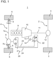
- FIG 1 illustrates a drive 1 for a commercial vehicle with two driven axles 2, 4.
- the motor vehicle is designed here as a commercial vehicle.
- the vehicle includes a conventional mechanical drive train for driving a rigid rear axle 2 of the motor vehicle.
- the mechanical drive train includes an internal combustion engine 9 , a transmission 10 and a drive shaft 11 which extends in the direction of the longitudinal axis of the vehicle and transmits the drive power to the rear axle 2 .
- the drive shaft 11 is connected to an axle differential 12 of the rear axle 2, via which the drive power is divided between the two rear wheels 3 essentially equally.
- the vehicle also includes a steerable front axle 4.
- the wheels 5 of the front axle 4 are attached to the chassis in a manner known per se with an independent wheel suspension 6.
- the front axle 4 thus has no rigid axle, i. That is, the front axle 4 does not have a continuous axle body that is connected to the frame/body of the vehicle via spring, damping, and guide elements.
- the front axle 4 can be driven by a hydraulic motor 21 (also referred to as a hydraulic motor) of a hydrostatic auxiliary drive 20 .
- the hydraulic motor 21 is operatively connected to an axle differential 8 of the front axle 4 .
- the two outputs of the axle differential in the form of the two output shafts 8e are each connected to one of the wheel drive shafts 7a, 7b in a rotationally fixed manner.
- the axis of rotation R of the drives or driven shafts 8e is represented by the dashed line R.
- the hydraulic motor 21 is integrated in a closed hydrostatic circuit known per se, with a hydraulic pump 22 being driven mechanically via the mechanical drive train of the vehicle and being hydraulically connected via fluid lines 23, 24 to the hydraulic motor 21 for energy transmission.
- One of the fluid lines 23, 24 forms a first branch to form a flow, while the other fluid line forms the second branch and thus the return of the hydraulic circuit.
- the hydraulic motor and the hydraulic pump 22 may be fixed or variable displacement.
- the hydraulic pump can be connected via a clutch 14 and a power take-off shaft 13 to a power take-off of the internal combustion engine 9 or, as in figure 1 shown, be flanged to a power take-off on the vehicle transmission 10.
- a feed pump (not shown) may also be provided to compensate for internal and external leakage levels that occur.
- the feed pump is connected to a supply (reservoir) of hydraulic fluid (not shown) via a hydraulic line.
- the hydraulic motor 21 and the hydraulic pump 22 can each be designed as hydrostatic radial piston machines.
- figure 2 shows an example of how the hydraulic motor 21 can be operatively connected to the axle differential 8 of the front axle 4 .
- the hydraulic motor 21 is fixed to the chassis.
- the embodiment variant shown has a drive shaft 25 driven by the hydraulic motor 21 at its distal end to a pinion gear 26 which meshes with the ring gear 8a of the axle differential 8 of the front axle 4 .
- the hydraulic motor 21 is integrated into a hydrostatic circuit 20 known per se, for example analogously to that in figure 1 example shown, wherein a hydraulic pump 22 is driven mechanically via the mechanical drive train of the vehicle containing the internal combustion engine 9 and is hydraulically connected to the hydraulic motor 21 via fluid lines.
- the ring gear 8a is connected in a manner known per se to the cage 8b of the axle differential 8 in a rotationally fixed manner.
- the axle differential is designed as a bevel gear differential, with a pair of axle bevel gears 8d and a pair of pinion gears 8c meshing with each other.
- the axle bevel gears 8d drive the wheel drive shafts 7a and 7b via the driven shafts 8e of the axle differential 8 and thus transmit the drive power of the hydraulic motor 21 to the front wheels 5.
- the hydraulic motor 21 is not arranged coaxially to the axis of rotation R of the drives 8e of the axle differential 8, but arranged spatially offset to the axis of rotation R.
- FIG 3 shows an alternative embodiment.
- the hydraulic motor 21 is not arranged axially offset to the axle differential 8 or to the axis of rotation R of the drives 8e of the axle differential 8 here.
- the hydraulic motor 21 is rather arranged coaxially to the axis of rotation R and drives the cage 8b of the axle differential 8 directly and thus replaces the ring gear 8a.
- the hydraulic motor 21 is designed as a radial piston motor, having an outer, stationary cam ring and an inner, revolving cylinder housing, which is non-rotatably connected to the cage 8b and can thus set this in a rotational movement.
- an axle pin carrying differential gears is mounted in the cage 8b, these differential gears 8c meshing with axle shaft gears 8d which are arranged on the wheel drive shafts 7a, 7b and are each designed as bevel gears.
- the hydraulic motor 21 can transmit its drive power to the wheels 5 of the second axle 4 either with or without a transmission gearing having a defined reduction or transmission ratio.
Landscapes
- Engineering & Computer Science (AREA)
- Chemical & Material Sciences (AREA)
- Combustion & Propulsion (AREA)
- Transportation (AREA)
- Mechanical Engineering (AREA)
- Motor Power Transmission Devices (AREA)
- Arrangement And Driving Of Transmission Devices (AREA)
- Retarders (AREA)
Claims (9)
- Véhicule automobile, à savoir véhicule utilitaire, comprenant un premier essieu rigide entraînable (2), qui peut être entraîné et/ou est entraîné par l'intermédiaire d'une chaîne cinématique mécanique (9, 10, 11, 12) présentant un moteur à combustion interne (9), et un deuxième essieu (4) dirigeable comprenant une suspension de roue individuelle, le deuxième essieu (4) pouvant être entraîné et/ou étant entraîné par un entraînement auxiliaire hydrostatique (20), dont la puissance d'entraînement est fournie par l'intermédiaire d'une prise de force prévue sur le moteur à combustion interne ou d'une prise de force prévue sur la transmission de véhicule de la chaîne cinématique mécanique, qui convertit la vitesse de rotation du moteur en vitesse de rotation d'entraînement, l'entraînement auxiliaire présentant un moteur hydraulique (21), qui répartit sa puissance d'entraînement entre les roues (5) du deuxième essieu (4) par l'intermédiaire d'une transmission solidaire du châssis, le premier essieu rigide étant le seul essieu rigide du véhicule utilitaire, caractérisé par une transmission à démultiplication avec une réduction ou une démultiplication prédéterminée, par laquelle le moteur hydraulique (21) est en liaison fonctionnelle avec les roues (5) du deuxième essieu (4).
- Véhicule automobile selon la revendication 1, dans lequel la transmission est un différentiel d'essieu (8) et le moteur hydraulique (21) est agencé coaxialement à une sortie (8e) du différentiel d'essieu (8).
- Véhicule automobile selon la revendication 2, dans lequel une partie du moteur hydraulique (21) pouvant tourner coaxialement à la sortie (8e) du différentiel d'essieu (8) est reliée fonctionnellement à une cage (8b) du différentiel d'essieu (8) du deuxième essieu (4) .
- Véhicule automobile selon la revendication 1, dans lequel la transmission est un différentiel d'essieu (8) et dans lequel le moteur hydraulique (21) n'est pas agencé coaxialement à une sortie (8e) du différentiel d'essieu (8) et un arbre d'entraînement (25) du moteur hydraulique (21) est relié fonctionnellement au différentiel d'essieu (8) du deuxième essieu (4).
- Véhicule automobile selon la revendication 1 ou 4, dans lequel la transmission est un engrenage différentiel à roues coniques (8), comprenant une couronne (8a), une paire de roues coniques d'essieu (8d) et une paire de roues coniques de compensation (8c), une roue motrice (26) montée sur un arbre d'entraînement (17) du moteur hydraulique (21) étant en prise avec la couronne (8a).
- Véhicule automobile selon l'une quelconque des revendications précédentes, dans lequel l'entraînement auxiliaire hydrostatique (20) présente une pompe hydraulique (22) entraînée par la chaîne cinématique mécanique (9, 10, 11, 12) par l'intermédiaire de la prise de force du moteur à combustion interne ou de la transmission de véhicule, qui est reliée au moteur hydraulique (21) par l'intermédiaire de conduites de travail hydrauliques (23, 24).
- Véhicule automobile selon la revendication 4 ou 5, dans lequel le moteur hydraulique (21) peut être accouplé et désaccouplé du différentiel d'essieu (8) du deuxième essieu (4) et/ou des arbres d'entraînement de roue (7a, 7b) du deuxième essieu (4) au moyen d'un accouplement ou d'une roue libre.
- Véhicule automobile selon la revendication 3, dans lequel un axe d'essieu portant des roues de compensation est logé dans la cage (8b) du différentiel d'essieu (8), ces roues de compensation s'engrenant avec des roues d'arbre d'essieu agencées sur des arbres d'entraînement de roue et ces roues étant configurées sous forme de roues coniques ; et dans lequel le moteur hydraulique (21) est un moteur à pistons radiaux, présentant un anneau de came extérieur fixe et un boîtier de cylindre intérieur circonférentiel, qui est relié de manière immobile en rotation à la cage (8b).
- Véhicule automobile selon l'une quelconque des revendications précédentes, dans lequel le véhicule automobile est un véhicule utilitaire léger.
Applications Claiming Priority (1)
| Application Number | Priority Date | Filing Date | Title |
|---|---|---|---|
| DE102018124014.7A DE102018124014A1 (de) | 2018-09-28 | 2018-09-28 | Kraftfahrzeug mit einem Hilfsantrieb für eine lenkbare Achse |
Publications (2)
| Publication Number | Publication Date |
|---|---|
| EP3628525A1 EP3628525A1 (fr) | 2020-04-01 |
| EP3628525B1 true EP3628525B1 (fr) | 2022-02-23 |
Family
ID=68069580
Family Applications (1)
| Application Number | Title | Priority Date | Filing Date |
|---|---|---|---|
| EP19199616.4A Active EP3628525B1 (fr) | 2018-09-28 | 2019-09-25 | Véhicule automobile doté d'un entraînement auxiliaire pour un essieu dirigeable |
Country Status (2)
| Country | Link |
|---|---|
| EP (1) | EP3628525B1 (fr) |
| DE (1) | DE102018124014A1 (fr) |
Families Citing this family (1)
| Publication number | Priority date | Publication date | Assignee | Title |
|---|---|---|---|---|
| FR3123832A1 (fr) * | 2021-06-11 | 2022-12-16 | Psa Automobiles Sa | Véhicule à circuit de transmission hydraulique contrôlé pour la répartition de couple entre trains |
Family Cites Families (6)
| Publication number | Priority date | Publication date | Assignee | Title |
|---|---|---|---|---|
| JP3430754B2 (ja) * | 1995-11-29 | 2003-07-28 | 日産自動車株式会社 | 四輪駆動車 |
| DE10159468C2 (de) * | 2001-12-04 | 2003-09-25 | Daimler Chrysler Ag | Modular aufgebauter Tragrahmen für ein Nutzfahrzeug |
| AT503973B1 (de) * | 2006-08-11 | 2008-06-15 | Man Nutzfahrzeuge Oesterreich | Quersperre für ''man-hydrodrive'' |
| DE102011118111A1 (de) * | 2011-11-09 | 2012-05-24 | Daimler Ag | Antriebsstrang für einen Kraftwagen |
| FR3033529B1 (fr) * | 2015-03-13 | 2018-05-18 | Poclain Hydraulics Industrie | Dispositif d'assistance hydraulique sur vehicule et procede de mise a vide d'un tel dispositif |
| FR3043372B1 (fr) * | 2015-11-10 | 2017-12-08 | Poclain Hydraulics Ind | Procede d'engagement de l'assistance hydraulique |
-
2018
- 2018-09-28 DE DE102018124014.7A patent/DE102018124014A1/de not_active Withdrawn
-
2019
- 2019-09-25 EP EP19199616.4A patent/EP3628525B1/fr active Active
Also Published As
| Publication number | Publication date |
|---|---|
| DE102018124014A1 (de) | 2020-04-02 |
| EP3628525A1 (fr) | 2020-04-01 |
Similar Documents
| Publication | Publication Date | Title |
|---|---|---|
| EP3165395B1 (fr) | Véhicule utilitaire, en particulier poids lourd, comprenant au moins un groupe d'essieu jumelé | |
| DE102012100865B4 (de) | Antriebsanordnung mit elektrischer Maschine und Kraftfahrzeug mit einer solchen Antriebsanordnung | |
| EP0414722B1 (fr) | Tracteur toutes roues motrices | |
| AT503359B1 (de) | Getriebemodul zur variablen drehmomentverteilung | |
| EP3888981B1 (fr) | Entraînement d'essieu | |
| DE102006038358B4 (de) | Achsantriebseinheit für einen Antriebsstrang | |
| EP2995533B1 (fr) | Chenille orientable | |
| EP3406474B1 (fr) | Dispositif d'entraînement hybride électro-hydraulique pour un véhicule automobile | |
| DE102022204749B4 (de) | Achssystem, Antriebssystem und Fahrzeug | |
| EP3012141B1 (fr) | Entrainement de roue hydraulique pour un vehicule automobile et son procede de fonctionnement | |
| DE69518507T2 (de) | Fahrantriebsvorrichtung für arbeitsfahrzeug | |
| DE102017110941A1 (de) | Feststellbremsanlage für ein Kraftfahrzeug und Kraftfahrzeug | |
| WO2005098278A2 (fr) | Boite de transfert | |
| DE102022204752A1 (de) | Achssystem, Antriebssystem und Fahrzeug | |
| DE4323539C1 (de) | Radlagereinheit eines Kraftfahrzeugs | |
| EP0262626A1 (fr) | Dispositif d'entraînement des roues de deux essieux | |
| EP0201493B1 (fr) | Vehicule a essieux multiples avec entrainement independant des roues | |
| EP3628525B1 (fr) | Véhicule automobile doté d'un entraînement auxiliaire pour un essieu dirigeable | |
| EP2559581A2 (fr) | Système d'entraînement pour un véhicule automobile équipé d'un système de freinage agissant comme un différentiel à blocage | |
| DE102017003905A1 (de) | Achsgetriebesystem, Antriebsachsensystem und Kraftfahrzeug | |
| DE3913487A1 (de) | Allradgetriebener ackerschlepper | |
| DE102017219967A1 (de) | Einzelradantrieb für ein Fahrzeug | |
| DE102016220477B4 (de) | Achsantriebssystem sowie Verfahren zur Steuerung eines Achsantriebssystems | |
| DE3411746C1 (de) | Allradantrieb fuer Kraftfahrzeuge | |
| DE102013013693A1 (de) | Differenzialgetriebe für eine Antriebsachse eines Kraftfahrzeugs |
Legal Events
| Date | Code | Title | Description |
|---|---|---|---|
| PUAI | Public reference made under article 153(3) epc to a published international application that has entered the european phase |
Free format text: ORIGINAL CODE: 0009012 |
|
| STAA | Information on the status of an ep patent application or granted ep patent |
Free format text: STATUS: THE APPLICATION HAS BEEN PUBLISHED |
|
| AK | Designated contracting states |
Kind code of ref document: A1 Designated state(s): AL AT BE BG CH CY CZ DE DK EE ES FI FR GB GR HR HU IE IS IT LI LT LU LV MC MK MT NL NO PL PT RO RS SE SI SK SM TR |
|
| AX | Request for extension of the european patent |
Extension state: BA ME |
|
| STAA | Information on the status of an ep patent application or granted ep patent |
Free format text: STATUS: REQUEST FOR EXAMINATION WAS MADE |
|
| 17P | Request for examination filed |
Effective date: 20200923 |
|
| RBV | Designated contracting states (corrected) |
Designated state(s): AL AT BE BG CH CY CZ DE DK EE ES FI FR GB GR HR HU IE IS IT LI LT LU LV MC MK MT NL NO PL PT RO RS SE SI SK SM TR |
|
| STAA | Information on the status of an ep patent application or granted ep patent |
Free format text: STATUS: EXAMINATION IS IN PROGRESS |
|
| 17Q | First examination report despatched |
Effective date: 20210212 |
|
| GRAP | Despatch of communication of intention to grant a patent |
Free format text: ORIGINAL CODE: EPIDOSNIGR1 |
|
| STAA | Information on the status of an ep patent application or granted ep patent |
Free format text: STATUS: GRANT OF PATENT IS INTENDED |
|
| INTG | Intention to grant announced |
Effective date: 20211202 |
|
| GRAS | Grant fee paid |
Free format text: ORIGINAL CODE: EPIDOSNIGR3 |
|
| GRAA | (expected) grant |
Free format text: ORIGINAL CODE: 0009210 |
|
| STAA | Information on the status of an ep patent application or granted ep patent |
Free format text: STATUS: THE PATENT HAS BEEN GRANTED |
|
| AK | Designated contracting states |
Kind code of ref document: B1 Designated state(s): AL AT BE BG CH CY CZ DE DK EE ES FI FR GB GR HR HU IE IS IT LI LT LU LV MC MK MT NL NO PL PT RO RS SE SI SK SM TR |
|
| REG | Reference to a national code |
Ref country code: GB Ref legal event code: FG4D Free format text: NOT ENGLISH |
|
| REG | Reference to a national code |
Ref country code: CH Ref legal event code: EP |
|
| REG | Reference to a national code |
Ref country code: AT Ref legal event code: REF Ref document number: 1470201 Country of ref document: AT Kind code of ref document: T Effective date: 20220315 |
|
| REG | Reference to a national code |
Ref country code: IE Ref legal event code: FG4D Free format text: LANGUAGE OF EP DOCUMENT: GERMAN |
|
| REG | Reference to a national code |
Ref country code: DE Ref legal event code: R096 Ref document number: 502019003473 Country of ref document: DE |
|
| REG | Reference to a national code |
Ref country code: SE Ref legal event code: TRGR |
|
| REG | Reference to a national code |
Ref country code: NL Ref legal event code: FP |
|
| REG | Reference to a national code |
Ref country code: LT Ref legal event code: MG9D |
|
| PG25 | Lapsed in a contracting state [announced via postgrant information from national office to epo] |
Ref country code: RS Free format text: LAPSE BECAUSE OF FAILURE TO SUBMIT A TRANSLATION OF THE DESCRIPTION OR TO PAY THE FEE WITHIN THE PRESCRIBED TIME-LIMIT Effective date: 20220223 Ref country code: PT Free format text: LAPSE BECAUSE OF FAILURE TO SUBMIT A TRANSLATION OF THE DESCRIPTION OR TO PAY THE FEE WITHIN THE PRESCRIBED TIME-LIMIT Effective date: 20220623 Ref country code: NO Free format text: LAPSE BECAUSE OF FAILURE TO SUBMIT A TRANSLATION OF THE DESCRIPTION OR TO PAY THE FEE WITHIN THE PRESCRIBED TIME-LIMIT Effective date: 20220523 Ref country code: LT Free format text: LAPSE BECAUSE OF FAILURE TO SUBMIT A TRANSLATION OF THE DESCRIPTION OR TO PAY THE FEE WITHIN THE PRESCRIBED TIME-LIMIT Effective date: 20220223 Ref country code: HR Free format text: LAPSE BECAUSE OF FAILURE TO SUBMIT A TRANSLATION OF THE DESCRIPTION OR TO PAY THE FEE WITHIN THE PRESCRIBED TIME-LIMIT Effective date: 20220223 Ref country code: ES Free format text: LAPSE BECAUSE OF FAILURE TO SUBMIT A TRANSLATION OF THE DESCRIPTION OR TO PAY THE FEE WITHIN THE PRESCRIBED TIME-LIMIT Effective date: 20220223 Ref country code: BG Free format text: LAPSE BECAUSE OF FAILURE TO SUBMIT A TRANSLATION OF THE DESCRIPTION OR TO PAY THE FEE WITHIN THE PRESCRIBED TIME-LIMIT Effective date: 20220523 |
|
| PG25 | Lapsed in a contracting state [announced via postgrant information from national office to epo] |
Ref country code: PL Free format text: LAPSE BECAUSE OF FAILURE TO SUBMIT A TRANSLATION OF THE DESCRIPTION OR TO PAY THE FEE WITHIN THE PRESCRIBED TIME-LIMIT Effective date: 20220223 Ref country code: LV Free format text: LAPSE BECAUSE OF FAILURE TO SUBMIT A TRANSLATION OF THE DESCRIPTION OR TO PAY THE FEE WITHIN THE PRESCRIBED TIME-LIMIT Effective date: 20220223 Ref country code: GR Free format text: LAPSE BECAUSE OF FAILURE TO SUBMIT A TRANSLATION OF THE DESCRIPTION OR TO PAY THE FEE WITHIN THE PRESCRIBED TIME-LIMIT Effective date: 20220524 Ref country code: FI Free format text: LAPSE BECAUSE OF FAILURE TO SUBMIT A TRANSLATION OF THE DESCRIPTION OR TO PAY THE FEE WITHIN THE PRESCRIBED TIME-LIMIT Effective date: 20220223 |
|
| PG25 | Lapsed in a contracting state [announced via postgrant information from national office to epo] |
Ref country code: IS Free format text: LAPSE BECAUSE OF FAILURE TO SUBMIT A TRANSLATION OF THE DESCRIPTION OR TO PAY THE FEE WITHIN THE PRESCRIBED TIME-LIMIT Effective date: 20220623 |
|
| PG25 | Lapsed in a contracting state [announced via postgrant information from national office to epo] |
Ref country code: SM Free format text: LAPSE BECAUSE OF FAILURE TO SUBMIT A TRANSLATION OF THE DESCRIPTION OR TO PAY THE FEE WITHIN THE PRESCRIBED TIME-LIMIT Effective date: 20220223 Ref country code: SK Free format text: LAPSE BECAUSE OF FAILURE TO SUBMIT A TRANSLATION OF THE DESCRIPTION OR TO PAY THE FEE WITHIN THE PRESCRIBED TIME-LIMIT Effective date: 20220223 Ref country code: RO Free format text: LAPSE BECAUSE OF FAILURE TO SUBMIT A TRANSLATION OF THE DESCRIPTION OR TO PAY THE FEE WITHIN THE PRESCRIBED TIME-LIMIT Effective date: 20220223 Ref country code: EE Free format text: LAPSE BECAUSE OF FAILURE TO SUBMIT A TRANSLATION OF THE DESCRIPTION OR TO PAY THE FEE WITHIN THE PRESCRIBED TIME-LIMIT Effective date: 20220223 Ref country code: DK Free format text: LAPSE BECAUSE OF FAILURE TO SUBMIT A TRANSLATION OF THE DESCRIPTION OR TO PAY THE FEE WITHIN THE PRESCRIBED TIME-LIMIT Effective date: 20220223 Ref country code: CZ Free format text: LAPSE BECAUSE OF FAILURE TO SUBMIT A TRANSLATION OF THE DESCRIPTION OR TO PAY THE FEE WITHIN THE PRESCRIBED TIME-LIMIT Effective date: 20220223 |
|
| REG | Reference to a national code |
Ref country code: DE Ref legal event code: R097 Ref document number: 502019003473 Country of ref document: DE |
|
| PG25 | Lapsed in a contracting state [announced via postgrant information from national office to epo] |
Ref country code: AL Free format text: LAPSE BECAUSE OF FAILURE TO SUBMIT A TRANSLATION OF THE DESCRIPTION OR TO PAY THE FEE WITHIN THE PRESCRIBED TIME-LIMIT Effective date: 20220223 |
|
| PLBE | No opposition filed within time limit |
Free format text: ORIGINAL CODE: 0009261 |
|
| STAA | Information on the status of an ep patent application or granted ep patent |
Free format text: STATUS: NO OPPOSITION FILED WITHIN TIME LIMIT |
|
| 26N | No opposition filed |
Effective date: 20221124 |
|
| PG25 | Lapsed in a contracting state [announced via postgrant information from national office to epo] |
Ref country code: SI Free format text: LAPSE BECAUSE OF FAILURE TO SUBMIT A TRANSLATION OF THE DESCRIPTION OR TO PAY THE FEE WITHIN THE PRESCRIBED TIME-LIMIT Effective date: 20220223 |
|
| PG25 | Lapsed in a contracting state [announced via postgrant information from national office to epo] |
Ref country code: MC Free format text: LAPSE BECAUSE OF FAILURE TO SUBMIT A TRANSLATION OF THE DESCRIPTION OR TO PAY THE FEE WITHIN THE PRESCRIBED TIME-LIMIT Effective date: 20220223 |
|
| REG | Reference to a national code |
Ref country code: CH Ref legal event code: PL |
|
| REG | Reference to a national code |
Ref country code: BE Ref legal event code: MM Effective date: 20220930 |
|
| PG25 | Lapsed in a contracting state [announced via postgrant information from national office to epo] |
Ref country code: LU Free format text: LAPSE BECAUSE OF NON-PAYMENT OF DUE FEES Effective date: 20220925 |
|
| PG25 | Lapsed in a contracting state [announced via postgrant information from national office to epo] |
Ref country code: LI Free format text: LAPSE BECAUSE OF NON-PAYMENT OF DUE FEES Effective date: 20220930 Ref country code: IE Free format text: LAPSE BECAUSE OF NON-PAYMENT OF DUE FEES Effective date: 20220925 Ref country code: CH Free format text: LAPSE BECAUSE OF NON-PAYMENT OF DUE FEES Effective date: 20220930 |
|
| PG25 | Lapsed in a contracting state [announced via postgrant information from national office to epo] |
Ref country code: BE Free format text: LAPSE BECAUSE OF NON-PAYMENT OF DUE FEES Effective date: 20220930 |
|
| PG25 | Lapsed in a contracting state [announced via postgrant information from national office to epo] |
Ref country code: HU Free format text: LAPSE BECAUSE OF FAILURE TO SUBMIT A TRANSLATION OF THE DESCRIPTION OR TO PAY THE FEE WITHIN THE PRESCRIBED TIME-LIMIT; INVALID AB INITIO Effective date: 20190925 |
|
| PG25 | Lapsed in a contracting state [announced via postgrant information from national office to epo] |
Ref country code: CY Free format text: LAPSE BECAUSE OF FAILURE TO SUBMIT A TRANSLATION OF THE DESCRIPTION OR TO PAY THE FEE WITHIN THE PRESCRIBED TIME-LIMIT Effective date: 20220223 |
|
| GBPC | Gb: european patent ceased through non-payment of renewal fee |
Effective date: 20230925 |
|
| PG25 | Lapsed in a contracting state [announced via postgrant information from national office to epo] |
Ref country code: MK Free format text: LAPSE BECAUSE OF FAILURE TO SUBMIT A TRANSLATION OF THE DESCRIPTION OR TO PAY THE FEE WITHIN THE PRESCRIBED TIME-LIMIT Effective date: 20220223 |
|
| PG25 | Lapsed in a contracting state [announced via postgrant information from national office to epo] |
Ref country code: GB Free format text: LAPSE BECAUSE OF NON-PAYMENT OF DUE FEES Effective date: 20230925 |
|
| PG25 | Lapsed in a contracting state [announced via postgrant information from national office to epo] |
Ref country code: GB Free format text: LAPSE BECAUSE OF NON-PAYMENT OF DUE FEES Effective date: 20230925 |
|
| PG25 | Lapsed in a contracting state [announced via postgrant information from national office to epo] |
Ref country code: MT Free format text: LAPSE BECAUSE OF FAILURE TO SUBMIT A TRANSLATION OF THE DESCRIPTION OR TO PAY THE FEE WITHIN THE PRESCRIBED TIME-LIMIT Effective date: 20220223 |
|
| PGFP | Annual fee paid to national office [announced via postgrant information from national office to epo] |
Ref country code: DE Payment date: 20250926 Year of fee payment: 7 |
|
| PGFP | Annual fee paid to national office [announced via postgrant information from national office to epo] |
Ref country code: NL Payment date: 20250925 Year of fee payment: 7 Ref country code: IT Payment date: 20250922 Year of fee payment: 7 |
|
| PGFP | Annual fee paid to national office [announced via postgrant information from national office to epo] |
Ref country code: FR Payment date: 20250925 Year of fee payment: 7 |
|
| PGFP | Annual fee paid to national office [announced via postgrant information from national office to epo] |
Ref country code: SE Payment date: 20250924 Year of fee payment: 7 |
|
| REG | Reference to a national code |
Ref country code: AT Ref legal event code: MM01 Ref document number: 1470201 Country of ref document: AT Kind code of ref document: T Effective date: 20240925 |
|
| PG25 | Lapsed in a contracting state [announced via postgrant information from national office to epo] |
Ref country code: TR Free format text: LAPSE BECAUSE OF FAILURE TO SUBMIT A TRANSLATION OF THE DESCRIPTION OR TO PAY THE FEE WITHIN THE PRESCRIBED TIME-LIMIT Effective date: 20220223 |
|
| PG25 | Lapsed in a contracting state [announced via postgrant information from national office to epo] |
Ref country code: AT Free format text: LAPSE BECAUSE OF NON-PAYMENT OF DUE FEES Effective date: 20240925 |
|
| PGFP | Annual fee paid to national office [announced via postgrant information from national office to epo] |
Ref country code: AT Payment date: 20260410 Year of fee payment: 5 |