EP3936722A1 - Partie de boîtier, en particulier une partie de boîtier d'un boîtier électronique, de préférence un terminal de compresseur électronique - Google Patents
Partie de boîtier, en particulier une partie de boîtier d'un boîtier électronique, de préférence un terminal de compresseur électronique Download PDFInfo
- Publication number
- EP3936722A1 EP3936722A1 EP20184235.8A EP20184235A EP3936722A1 EP 3936722 A1 EP3936722 A1 EP 3936722A1 EP 20184235 A EP20184235 A EP 20184235A EP 3936722 A1 EP3936722 A1 EP 3936722A1
- Authority
- EP
- European Patent Office
- Prior art keywords
- housing part
- housing
- compressor
- pulled
- edge
- Prior art date
- Legal status (The legal status is an assumption and is not a legal conclusion. Google has not performed a legal analysis and makes no representation as to the accuracy of the status listed.)
- Granted
Links
Images


Classifications
-
- F—MECHANICAL ENGINEERING; LIGHTING; HEATING; WEAPONS; BLASTING
- F04—POSITIVE - DISPLACEMENT MACHINES FOR LIQUIDS; PUMPS FOR LIQUIDS OR ELASTIC FLUIDS
- F04B—POSITIVE-DISPLACEMENT MACHINES FOR LIQUIDS; PUMPS
- F04B39/00—Component parts, details, or accessories, of pumps or pumping systems specially adapted for elastic fluids, not otherwise provided for in, or of interest apart from, groups F04B25/00 - F04B37/00
- F04B39/14—Provisions for readily assembling or disassembling
-
- H—ELECTRICITY
- H05—ELECTRIC TECHNIQUES NOT OTHERWISE PROVIDED FOR
- H05K—PRINTED CIRCUITS; CASINGS OR CONSTRUCTIONAL DETAILS OF ELECTRIC APPARATUS; MANUFACTURE OF ASSEMBLAGES OF ELECTRICAL COMPONENTS
- H05K5/00—Casings, cabinets or drawers for electric apparatus
- H05K5/02—Details
- H05K5/0217—Mechanical details of casings
-
- H—ELECTRICITY
- H05—ELECTRIC TECHNIQUES NOT OTHERWISE PROVIDED FOR
- H05K—PRINTED CIRCUITS; CASINGS OR CONSTRUCTIONAL DETAILS OF ELECTRIC APPARATUS; MANUFACTURE OF ASSEMBLAGES OF ELECTRICAL COMPONENTS
- H05K5/00—Casings, cabinets or drawers for electric apparatus
- H05K5/02—Details
- H05K5/0247—Electrical details of casings, e.g. terminals, passages for cables or wiring
-
- F—MECHANICAL ENGINEERING; LIGHTING; HEATING; WEAPONS; BLASTING
- F04—POSITIVE - DISPLACEMENT MACHINES FOR LIQUIDS; PUMPS FOR LIQUIDS OR ELASTIC FLUIDS
- F04C—ROTARY-PISTON, OR OSCILLATING-PISTON, POSITIVE-DISPLACEMENT MACHINES FOR LIQUIDS; ROTARY-PISTON, OR OSCILLATING-PISTON, POSITIVE-DISPLACEMENT PUMPS
- F04C2240/00—Components
- F04C2240/80—Other components
- F04C2240/803—Electric connectors or cables; Fittings therefor
Definitions
- the invention relates to a housing part, especially a housing component, in particular to be attached to a housing which accommodates an electronic compressor.
- the housing part is therefore denoted as e-compressor terminal.
- the housing part can be charachterized as a feedthrough assembly.
- the invention also relates to an electric compressor comprising a a housing part or a housing component as an e-compressor terminal according to the invention.
- Housings for electronic components preferably include a plurality of feedthroughs in order to guide wires from outside to the inner part of the housing, which accommodates e. g. parts of an electronic compressor in the housing.
- Housing parts comprising at least one conductor fed through an opening into a housing suffer from a low bending stiffness. Further the pressure resistance of housing parts according to the state of the art was low. The positioning of the housing parts, especial e-compressor terminals have been difficult. Also the evenness and the sealing in the state of the art was defective, and their long-term reliability deserves improvement. The defectiveness of the evenness especially arises when a spigot is used for centering the housing component or the so called GTMS plate to a housing which accommodates electric compressor and the spigot was situated in the center of the GTMS plate or the housing component.
- a housing part should be specified which is characterized having a high stiffness and pressure resistance. Further an improved centering of the housing part, especially the glass metal plate comprising the feedthroughs to a housing with a high flatness should be possible.
- a housing part according to the invention comprises at least one opening for at least one conductor embedded in a glass or a glass ceramic material that is fed into each of the respective openings providing a glass-metal seal (GTMS).
- GTMS also comprises glass ceramic materials and the like. As generally known, those represent a group of inorganic materials which are capable of electrically insulating the conductor from the housing part and to seal the openings.
- said housing part or housing component in particular for a housing, preferably an e-compressor housing, comprises a structure for centering the housing part at a structure of the housing to which the housing part is to be attached.
- Such structure for centering is according to the invention represented in a first alternative by a recess area.
- this can be a protrusion.
- the housing part can be affixed to the structure by screws in at least two bores, e.g. screw bores at the edge of the GTMS plate or housing part.
- the housing part, especially e-compressor terminal according to the invention furthermore comprises a structure for enhancing the housing parts resilience against bending, or with other words, enhances the stiffness of the housing part, especially the e-compressor terminal.
- This structure or structures for enhancing the housing parts resilience against bending are represented e.g.by at least one pulled up edge.
- the pulled up edge could surround the complete edge of the housing part, e.g. the GTMS plate or only a part of the edge, e.g. the central part.
- the enhancement of the stiffness, especially the bending stiffness which leads to a higher compression onto the glass or glass-ceramic material through which a conductor is fed by the housing part are the following:
- a tight sealing means that the helium leakage rate is lower than 10 -8 mbar l/sec for a pressure difference of 1 bar.
- the structural steel which most preferred is used comprises Ni, Nb, Ti, Al, V as alloy components.
- the stiffness is increased by 10 to 30% if such a material is used for the housing part.
- Structural steel is normally a carbon steel. If the stiffness can enhanced by one or more of the above mentioned measurement e.g. using a structural steel in form of microalloyed steel and/or providing a recess then the thickness of the housing part can be reduced without the compression e.g.
- microalloyed steel as material has several advantages.
- One further advantage beside the high stiffness is the fact that a body of microalloyed steel in contast to normal structural steel has a lower weight. This is due to the fact that because of the high stiffness and yield strength of microalloyed steel, the wall thickness of the body can be reduced. The yield strength and therefore the stiffness of normal steel is reduced when e.g. the conductor is brought in or glassed into a glass or glass ceramic material due to the high temperature of this process. The yield strength of microalloyed steel is not so prominent reduced by high temperatures.
- the yield strength and therefore stiffness of microalloyed steel is significantly higher after a temperature glassing process compared to that of a normal steel.
- the higher yield strength and therefore stiffness then can result in a higher compression of the metal onto the glass or glass-ceramic material.
- the higher yield strength and therefore stiffness is advantageous for the housing part because it then can better withstand the pressure load from inside the housing onto which the housing part is mounted. A leaking between the housing part and the housing is prevented by the stiffer housing part.
- structure in the meaning of this disclosure covers all means, especially all geometrical means, which are attached and/or formed-in at the housing part which is subject to the invention.
- the housing part represents an elongated structure.
- the housing part is longer than wide, beneficially a multiple times longer than wide. This especially is the case for embodiments which comprise a plurality of openings, which means more than one opening.
- Such elongated structures are especially prone to bending issues.
- the recess area can be formed by using a stamping and/or reforming process.
- the housing part, specifically the base of the housing part, and the recess area are a one-piece part.
- the recess area is formed from the base of the housing part, elevating over or under the plane of the base.
- the reforming and/or stamping has the further advantage, that there is no bonding line between the base area and the recess area of the housing part, which could have effects on the long-term stability of the finished housing part. It has to be taken into account that especially in the e-compressor application the housing part is exposed to temperature changes over a large interval of temperatures, temperature shocks and/or vibrations. Any existing mechanical connection between separate parts, in this case the base area and the recess area, could induce mechanical stress and therefore also deformation into the recess area, which normally has the function to seal the housing to which the housing part is attached. Any deformation could lead to a loss of sealing capabilities and therefore might reduce the long-term reliability of the interconnection of the housing and the attached housing part.
- the recess area represents a plane which is elevated from the plane of the base of the housing part.
- the recess area has a side wall which extends from the base of the housing part.
- the transition of the base of the housing part and the side wall is rounded, preferably with a radius R. This helps to enhance the mechanical long term stability of the housing part, since the housing part is normally made of metal, and the rounded transition especially together with the one-piece design reduces the risk of the formation of initial cracks of the metal structure.
- the value of R can of course be dependent on the overall dimensions of the housing part. In a common application for an e-compressor, R is advantageously between 0.01 mm and 0,8 mm.
- the side wall can be perpendicular to the plane of the base of the housing part, but could also be in another angle or sloped, in order to be pressed in or to be even better centered into the structure of the housing to which the housing part is attached.
- the pulled up edge could be a separate part, which could be joined with the plate like element of the housing part by fusing.
- the advantage of the pulled up part to be a separate part is that production of both parts - plate like element and pulled up part - could be organized separately. Because the pulled up edge is attached to the base part of the housing and therefore away from the sealing area, the bondline between the pulled up edge and the base of the housing part is assumed not to interfere with the long term sealing capabilities of the recess area as discussed above.
- the housing part is reshaped in order to provide the pulled up edge.
- a reshaping process could be e. g. stamping the plate like element in order to provide a recess. This reforming and/or reshaping again leads to a one-piece part with all the advantages caused by the absence of a mechanical bondline as discussed above.
- the recess area has, at least at the side to be connected to the housing, a flatness according to DIN ISO 1101 of at least 0.1, preferably at least 0,07, most preferably from 0.01 to 0.07.
- the recess area serves to seal the housing from the environment. Therefore a good flatness can be achieved by the aforesaid structures, i.e. the recess area which represents a one-piece part and the pulled up edges, and this flatness is achieved during operations and a long term period of time. Therefore, the recess area and the pulled up edge work together to achieve those beneficial behavior.
- This also allows to reduce the thickness of the housing part and thereby to reduce the amount of material needed. This helps to reduce the overall weight and therefore to increase the efficiency of e.g. vehicles which comprise an e-compressor with the inventive housing.
- At least one conductor and the glass or glass ceramic material form a compression seal.
- a compression seal it is possible to provide a hermetical seal.
- a He leakage rate of better then 1 ⁇ 10 -8 mbar l/min can be achieved by a compression seal.
- the term compression seal is commonly known. It generally means that the thermal expansion of the glass or glass ceramic material is smaller than the thermal expansion of the surrounding material, so that, as the glass or glass ceramic material solidifies when it is melted in, the surrounding material so to say 'shrinks' onto the glass or glass ceramic material and thereby exerts a permanent compressive stress on the glass or glass ceramic material, which improves the mechanical pressure resistance.
- the housing part comprises as a material steel, especially stainless steel, most preferred structural steel, preferably microalloyed steel, most preferred structural steel in form of microalloyed steel.
- Microalloyed steel is a type of alloy steel that contains small amounts of alloying elements (0,05 to 0,15 %), including niobium, vanadium, titanium, molybdenum, zirconium, boron and rare-earth metals. They are used to refine the grain microstructure or facilitate precipitation hardening.
- the yield strength of microalloyed steel is between 275 and 750 MPa without heat treatment. Weldability is good, and can even be improved by reducing carbon content while maintaining strength. Fatigue life and wear resistance are superior to similar heat-treated steels.
- microalloyed steels do not require as much cold working to achieve the same strength as other carbon steel; this also leads to greater ductility.
- microalloyed steel as material, a high bending stiffness and strength could be provided. The advantages of the usage of a microalloyed steel instead of a normal or structural steel is described before in the application.
- the housing part in order to position and/or mount the housing part to the housing, e.g. when used for an electric compressor, can comprise at least a protrusion.
- the housing part can comprise at least one attachment bore such as a screw bore.
- the GTMS plate comprises two attachment and/or screw bores at the edges of the GTMS plate or the housing part.
- the housing part has, in the area of the elevated plane of the recess area, a structure, which advantageously enhances the surface area.
- This structure preferably is a stamped-in and/or reformed structure.
- the structure has an undercut. This can be achieved by stamping and subsequent reforming.
- the housing part comprises in the area of the openings a plastic material.
- the plastic material serves as further electrical insulation of the conductors which are fixed in the openings.
- This plastic can also contribute to reduce the risk of short currents, especially in case of wet or humid surroundings, when a water layer and/or dirt layer or the like might deposit on the surface of the glass or glass ceramic material. Since the openings are within the recess area, this means that the surface of the recess area can encompass said structures, specifically the surface at the outer side of the housing.
- At least a part of the structure of the elevated plane of the recess area has a roughness e.g. provided by a stamping or a embossing process for a casting compound which connects metal to an adhesive. Due to the good adhesion a save connection between the metal material and a plastic material is provided.
- the housing can comprise opposite to the opening or the screw bores for centering the housing part, especially the GTMS plate, a bushing attached to the housing or the housing part, e.g. by welding or brazing.
- the inventive housing part or GTMS plate with a recess area and/or a screw bore and/or protrusions can be used for an e-compressor terminal.
- the e-compressor terminal is used in an electric compressor.
- Electric compressors or e-compressors are widely used in environmentally friendly vehicles to support the operation of the air conditioning system.
- Electric and hybrid vehicles are equipped with battery powered electric compressors.
- the electric compressors must be hermetically sealed and function with their own motor inside.
- E-Compressor terminals or feedthroughs are important components of electric compressors and must be designed and manufactured carefully for optimal performance.
- An e-compressor terminal enables the transfer of large amounts of energy from the battery to the air conditioning compressor, and at the same time must remain reliably gas-tight to prevent refrigerant leakage.
- Electric compressors have very high performance and durability requirements while also being subjected to harsh environmental conditions. These include high pressure, high humidity and vibration. Compressor terminals or feedthroughs must be able to withstand such adverse conditions without issue. Highly controlled and precise processes are necessary to provide long-term reliable gas-tightness. Moreover, the compressor terminals must deliver extremely high insulation resistance and high voltage capabilities to support future quick-charging technology developments. High current capabilities are also essential to enable upcoming 48V electrical systems. This can be achieved with the inventive housing part when used in an e-compressor as an e-compressor terminal.
- the inventive housing part is preferably an e-compressor terminal.
- E-compressor terminals are important components of electric compressors and must be designed and manufactured to enable the transfer of large amounts of energy from the battery to the air conditioning compressor and at the same time remain reliably gas-tight to prevent any leakage, especially of refrigerant. Furthermore, electric compressors are effected by high pressure, high humidity and vibration.
- Compressor terminals must be able to withstand such adverse conditions. Furthermore, a compressor terminal must have extremely high insulation resistance and high voltage capabilities for e. g. 48V electrical systems.
- Fig. 1 is a cross-sectional view of a housing part 1, especially in a plate like form, which can be used as an e-compressor terminal with three conductors, 3.1, 3.2, 3.3, fed through three openings, 4.1, 4.2, 4.3. All three conductors 3.1, 3.2, 3.3 are fed through the openings 4.1, 4.2, 4.3 in a glass or glass ceramic material 6.1, 6.2, 6.3.
- the glass or glass ceramic material 6.1, 6.2, 6.3 comprises for example a soda barium glass.
- the material of the conductors 4.1, 4.2, 4.3 can, for example, be Cu, cored Fe-Cr, copper or Fe-Cr.
- the material of the housing part or the housing component is preferably steel, especially structural steel or stainless steel, most preferably micro alloyed steel.
- the usage of micoalloyed steel as material has several advantages. One advantage is the higher stiffness and the higher yield strength. Furthermore a body of microalloyed steel provides for a lower weight then normal steel due to thinner wall thicknesses. Also under temperature e.g. in a glassing process the yield strength and therefore stiffness of microalloyed steel is not so prominent reduced as in the case of structural steel.
- the inventive housing part 1 as shown in fig. 1 further comprises two bores, especially screw bores 11.1, 11.2, comprising a screw 17 which is used for mounting and/or positioning the housing part, especially the e-compressor terminal in relation to the housing of the e-compressor.
- the centering of the housing to the housing part of the e-compressor terminal is provided by the two protrusions 9, which are part of the compressor housing.
- the housing also comprises two bores as well as the housing part.
- the housing part Attached to the housing part are two bushings 12.1, 12.2 with a thread into which screws 17 are screwed.
- the housing part, especially the e-compressor terminal can be attached to the housing, especially the compressor housing e.g. by screws
- the bushings 12.1, 12.2 are welded in a gas-tight manner to the housing and/or housing part, especially the e-compressor terminal.
- Fig. 2 shows in detail the housing and the housing part 1 in form of an e-compressor terminal with one of the two bores, especially screw bores 11.2 at each side of the GTMS plate 1 through which a screw 17 is fed into the bushing 12.2.
- the bushing 12.2 is welded to the housing and/or housing part in an air-tight manner.
- a screw 10.2 is feed through each of the screw bores 11.2 of the housing part 1 and fastened in said bushing so that the housing part, especially the e-compressor terminal 1 is fixed to the housing, especially the compressor housing15 comprising the compressor tightly.
- the housing 15 is centered to the housing part by protrusions 9 of the housing.
- the housing part is fastened to the housing by a screw 17 in the bore 11.2.
- Fig. 3 shows a top view of a housing part of an e-compressor to which the housing, especially the e-compressor housing is attached.
- the screw bores 10.1, 10.2 as well as the three openings 4.1, 4.2, 4.3 through which the conductors 3.1, 3.2, 3.3 of the compressor terminal are fed.
- screws are fed e.g. to a bushing and the housing part, especially e-compressor terminalis securely fixed to the housing, especially the e-compressor housing.
- the roughness can be provided by stamping or a embossing process.
- the area 50 is adjacent to the three conductors 4.1, 4.2, 4.3 and provides for a better connection of a plastic material and the e-compressor terminal, which normally comprises a metal such as steel, stainless steel, preferably a structural steel especially a structural steel preferably in form of a microalloyed steel.
- Fig. 4 is a cross sectional view through a housing part in a second embodiment of the invention with two bores and two protrusions 202.1, 202.2, which fit e.g. into two bores of the housing.
- the protrusions serve only for centering the housing components to the housing comprising the e-compressor but not attaching the same to the housing e.g. by screws.
- the screw bores are separate from the centering bores as shown in fig. 5 .
- the screw bores are denoted with reference number 210.1 and 210.2 and the protrusions with 211.1 and 211.2.
- the housing part comprises three conductors 203.1, 203.2, 203.3 fed through three openings 204.1, 204.2, 204.3 of the housing part 200.
- the housing part is in a plate like form but comprises edges in a pulled up form, so called pulled up edges 201. By the pulled up edge 201 the housing part provides for a higher stiffness and a higher pressure resistance.
- the plate like part of the housing part especially the e-compressor terminal and the pulled up edge 201 of the housing part are a one part element. This is possible if the pulled up edge is formed e.g. by a stamping or a forming process out of the plate like element.
- Stamping or forming is a very cheap process for forming the pulled up edge 201.
- the height H of the pulled up edge 201 is preferably between 4 mm and 8 mm, most preferred 6 mm.
- the thickness D of the plate like element is between 1 mm and 3 mm, preferred 1,5 mm and 2,5 mm, most preferred 2,5 mm.
- Each of the conductors 203.1, 203.2, 203.3 is fed through each of the openings molten in a glass material 206.1, 206.2, 206.3 which provides for a gas tight sealing, a so called pressure sealing.
- Figure 6 shows a different embodiment of the invention also in a cross-sectional view.
- the e-compressor terminal or housing part shown in fig. 6 has a pulled up edge 100 and a recess 110 formed into the plate like element 120 by e.g. a stamping process.
- the pulled up edge is only in the central part of the plate like element of fig. 6 as shown in fig.10 .
- this embodiment also comprises three openings 104.1, 104.2, 104.3, through which conductors are fed.
- the plate like element comprises two bores 111.1, 111.2, through which a screw can be fed in order to position and fix the housing part, especially the e-compressor terminal to a housing, especially an e-compressor housing.
- the screw is not shown in fig. 6 .
- the screw bores of the embodiment in fig. 6 is not necessary for the centering of the housing part to the housing, e.g. the compressor housing.
- the centering is made in this embodiment by the recess area of the housing part or the GTMS plate.
- the screws are only needed to fix the housing part to the e-compressor housing. Therefore the screw are beneficial, but not necessary.
- the direction of stamping the plate like element is denoted by 113.
- the recess 110 can easily be formed.
- the recess 110 is used for a centering of the housing part especially the plate like element or e-compressor terminal in relation to the e-compressor housing.
- the stiffness of the plate like element could be enhanced.
- the complete housing part can be formed by a forming process, comprising inter alia stamping of the recess as well as forming the pulled up edge 100.
- the housing part especially for an e-compressor, can provide for a higher stiffness and a higher pressure resistance.
- fig. 7 shows the pulled up edge 100 as well as one opening 104.2 through which a conductor is fed.
- material for the housing part especially for an e-compressor terminal, steel is used. A stiffness about more than 15-30% higher than in common systems is reached, in case as a material for the housing part, a micro alloyed steel is used. Instead of the micro alloyed steel also normal steel or stainless steel can be used.
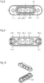
- Fig. 8 is a lower view of the housing part of fig. 6 and 7 , especially for an e-compressor terminal. Equal elements as in figs. 6 and 7 are denoted with the same reference numbers. In fig. 8 clearly shown are the three openings 104.1, 104.2, 104.3 as well as the bores 120.1, 120.2 through which screws for mounting the housing part to the housing e.g. of an e-compressor are shown. In Fig. 8 the three openings 104.1, 104.2, 104.3 are surrounded by a seal area 180. In the seal area 180 a surface seal between the housing part, especially the e-compressor terminal and the housing, especially the e-compressor housing is provided. By the seal in the sealing area the e-compressor terminal or housing part can connected to the e-compressor housing in a thight manner.
- Fig. 9 shows the housing of an e-compressor, in an upper view onto which the housing part is attached. All three openings 104.1, 104.2, 104.3 for the conductors can be seen. Further to the openings 104.1, 104.2, 104.3, two bores for screws in order to attach the housing part, especially the e-compressor terminal, to the housing of an e-compressor, is shown and denoted with reference number 111.1, 111.2. Each bore comprises an area 120.1, 120.2 which surrounds the bores 111.1, 111.2. These areas are flatness areas for the screw heads of the screws which are fed into the bores. The flatness areas prevent that the screws are fitted.
- Fig. 10 denotes a 3D-picture of the e-compressor terminal. What could be seen quite clear is the pulled up edge, which provides for a higher stiffness of the element. Further as is apparent from fig. 10 the pulled up edge 100 of the embodiment of fig. 6 to fig. 10 does not surround the whole plate like element like in fig. 4 and 5 but only the central part. Even if the pulled up edge is concentrated to the central part as in the embodiment of Fig. 6 to 10 the stiffness of the plate like element can be enhanced sufficiently.
- the e-compressor terminal of fig. 10 can be commended in a thight manner to the housing of the e-compressor.
- the inventive housing part provides for an improved stiffness and pressure resistance as well as a housing part which can be centered easily, e.g. to the housing to which the housing part should be attached. Further the invention provides a tight seal, between the housing part and the housing to which the housing part is attached due to the high evenness. Furthermore a tight feedthrough of the conductors in a glass or glass ceramic material is provided. Furthermore the housing part has a high yield strength. The pressure resistance of the housing part in form of a cover is very high and therefore the housing part is tightly connected to the e-compressor housing.
Landscapes
- Engineering & Computer Science (AREA)
- Microelectronics & Electronic Packaging (AREA)
- Mechanical Engineering (AREA)
- General Engineering & Computer Science (AREA)
- Compressor (AREA)
Priority Applications (7)
| Application Number | Priority Date | Filing Date | Title |
|---|---|---|---|
| EP20184235.8A EP3936722B1 (fr) | 2020-07-06 | 2020-07-06 | Partie de boîtier, en particulier une partie de boîtier d'un boîtier électronique, de préférence un terminal de compresseur électronique |
| KR1020237001439A KR20230035040A (ko) | 2020-07-06 | 2021-07-01 | 하우징 부품, 특히 전자 하우징용 하우징 부품, 바람직하게는 e-압축기 단자 |
| JP2023500288A JP7721627B2 (ja) | 2020-07-06 | 2021-07-01 | ハウジング部材、特に電子ハウジング用のハウジング部材、好ましくは電動コンプレッサ端子 |
| CN202180047841.6A CN115803526A (zh) | 2020-07-06 | 2021-07-01 | 外壳部件、尤其是用于电子外壳的外壳部件、优选电动压缩机端子 |
| PCT/EP2021/068201 WO2022008344A1 (fr) | 2020-07-06 | 2021-07-01 | Partie de boîtier, notamment partie de boîtier en particulier pour un boîtier électronique, de préférence une borne de compresseur électronique |
| EP21737680.5A EP4133181A1 (fr) | 2020-07-06 | 2021-07-01 | Partie de boîtier, notamment partie de boîtier en particulier pour un boîtier électronique, de préférence une borne de compresseur électronique |
| US18/093,651 US20230156937A1 (en) | 2020-07-06 | 2023-01-05 | Housing part, especially housing part in particular for an electronic housing, such as an e-compressor terminal |
Applications Claiming Priority (1)
| Application Number | Priority Date | Filing Date | Title |
|---|---|---|---|
| EP20184235.8A EP3936722B1 (fr) | 2020-07-06 | 2020-07-06 | Partie de boîtier, en particulier une partie de boîtier d'un boîtier électronique, de préférence un terminal de compresseur électronique |
Publications (2)
| Publication Number | Publication Date |
|---|---|
| EP3936722A1 true EP3936722A1 (fr) | 2022-01-12 |
| EP3936722B1 EP3936722B1 (fr) | 2024-09-04 |
Family
ID=71515073
Family Applications (2)
| Application Number | Title | Priority Date | Filing Date |
|---|---|---|---|
| EP20184235.8A Active EP3936722B1 (fr) | 2020-07-06 | 2020-07-06 | Partie de boîtier, en particulier une partie de boîtier d'un boîtier électronique, de préférence un terminal de compresseur électronique |
| EP21737680.5A Withdrawn EP4133181A1 (fr) | 2020-07-06 | 2021-07-01 | Partie de boîtier, notamment partie de boîtier en particulier pour un boîtier électronique, de préférence une borne de compresseur électronique |
Family Applications After (1)
| Application Number | Title | Priority Date | Filing Date |
|---|---|---|---|
| EP21737680.5A Withdrawn EP4133181A1 (fr) | 2020-07-06 | 2021-07-01 | Partie de boîtier, notamment partie de boîtier en particulier pour un boîtier électronique, de préférence une borne de compresseur électronique |
Country Status (6)
| Country | Link |
|---|---|
| US (1) | US20230156937A1 (fr) |
| EP (2) | EP3936722B1 (fr) |
| JP (1) | JP7721627B2 (fr) |
| KR (1) | KR20230035040A (fr) |
| CN (1) | CN115803526A (fr) |
| WO (1) | WO2022008344A1 (fr) |
Cited By (1)
| Publication number | Priority date | Publication date | Assignee | Title |
|---|---|---|---|---|
| DE102024125573A1 (de) | 2024-09-06 | 2026-03-12 | Schott Ag | Elektrische Durchführung |
Families Citing this family (8)
| Publication number | Priority date | Publication date | Assignee | Title |
|---|---|---|---|---|
| DE102023120482A1 (de) * | 2022-10-28 | 2024-05-08 | Hanon Systems | Dichtungsanordnung für eine Vorrichtung zum Antreiben eines Verdichters und Vorrichtung zum Antreiben eines Verdichters sowie ein Verfahren zum Herstellen einer Verbindungsanordnung |
| KR20240097550A (ko) * | 2022-12-20 | 2024-06-27 | 한온시스템 주식회사 | 전동 압축기 |
| EP4428368B1 (fr) | 2023-03-07 | 2025-01-15 | Schott Ag | Ensemble de traversée électrique |
| EP4530467A1 (fr) * | 2023-09-29 | 2025-04-02 | Schott Ag | Ensemble de traversée électrique à distance de fluage augmentée |
| EP4551815B1 (fr) * | 2023-09-29 | 2025-08-13 | Schott Ag | Ensemble de traversée électrique à distance de fluage augmentée |
| EP4530466A1 (fr) * | 2023-09-29 | 2025-04-02 | Schott Ag | Ensemble de traversée électrique |
| EP4704258A1 (fr) * | 2024-09-03 | 2026-03-04 | Schott Ag | Ensemble de traversée électrique |
| DE102024125575A1 (de) * | 2024-09-06 | 2026-03-12 | Schott Ag | Elektrische Durchführung und Verfahren zu deren Herstellung |
Citations (7)
| Publication number | Priority date | Publication date | Assignee | Title |
|---|---|---|---|---|
| US4964788A (en) * | 1990-03-21 | 1990-10-23 | Tecumseh Products Company | Hermetic terminal with terminal pin assemblies having fusible links and motor compressor unit including same |
| EP2218915A1 (fr) * | 2007-11-30 | 2010-08-18 | Kabushiki Kaisha Kobe Seiko Sho | Compresseur à vis |
| WO2012041472A1 (fr) * | 2010-10-01 | 2012-04-05 | Valeo Thermal Systems Japan Corporation | Dispositif de raccordement electrique d'un compresseur electrique |
| EP2439826A1 (fr) * | 2010-10-07 | 2012-04-11 | Kabushiki Kaisha Toyota Jidoshokki | Entrée de câbles étanche pour compresseur motorisé |
| EP2716913A2 (fr) * | 2012-10-02 | 2014-04-09 | Kabushiki Kaisha Toyota Jidoshokki | Compresseur motorisé |
| CH709991A2 (de) * | 2014-08-14 | 2016-02-15 | Schott Ag | Elektrische Durchführung und ihre Verwendung. |
| KR20190094611A (ko) * | 2018-02-05 | 2019-08-14 | 주식회사 실텍 | 자동차용 전동압축기의 밀봉 피드스루 |
Family Cites Families (23)
| Publication number | Priority date | Publication date | Assignee | Title |
|---|---|---|---|---|
| GB925534A (en) * | 1960-06-30 | 1963-05-08 | Gen Electric Co Ltd | Improvements in or relating to glass-to-metal seals |
| US5584716A (en) * | 1994-07-14 | 1996-12-17 | Copeland Corporation | Terminal assembly for hermetic compressor |
| US6841731B1 (en) * | 2003-12-18 | 2005-01-11 | Emerson Electric Co. | Terminal assembly |
| US7725190B2 (en) * | 2006-01-30 | 2010-05-25 | Medtronic, Inc. | Implantable medical device feedthrough assembly including flange plate |
| WO2009143123A2 (fr) * | 2008-05-19 | 2009-11-26 | Emerson Electric Co. | Traversée de borne d'alimentation électrique |
| CN102013581A (zh) * | 2010-09-30 | 2011-04-13 | 高文彬 | 电力绝缘子烧结密封端子板 |
| JP5267601B2 (ja) * | 2011-03-08 | 2013-08-21 | 株式会社豊田自動織機 | 電動圧縮機 |
| HUE051418T2 (hu) * | 2011-06-10 | 2021-03-01 | Schott Ag | Átvezetés |
| JP5542765B2 (ja) * | 2011-09-26 | 2014-07-09 | 日立オートモティブシステムズ株式会社 | パワーモジュール |
| EP2854174B1 (fr) * | 2012-05-22 | 2019-02-20 | Panasonic Intellectual Property Management Co., Ltd. | Dispositif à semi-conducteurs et son procédé de fabrication |
| US8946957B2 (en) * | 2012-10-24 | 2015-02-03 | Caterpillar Inc. | Cable arrangement system |
| JP6076819B2 (ja) * | 2013-04-24 | 2017-02-08 | 株式会社前川製作所 | 密閉型圧縮機 |
| US9208929B2 (en) * | 2013-09-20 | 2015-12-08 | Schott Corporation | GTMS connector for oil and gas market |
| DE102014016601A1 (de) * | 2014-11-11 | 2016-05-12 | Schott Ag | Bauteil mit Bauteilverstärkung und Durchführung |
| DE102014016600A1 (de) * | 2014-11-11 | 2016-05-12 | Schott Ag | Durchführung |
| CN106663893B (zh) * | 2015-09-25 | 2019-11-05 | 华为技术有限公司 | 一种连接器及通信终端 |
| US10702704B2 (en) * | 2016-05-20 | 2020-07-07 | E.K. Licensing, Llc | Pain relief utilizing polymer based materials or a combination of LED bulbs, polymer based materials and a near field accelerator |
| WO2018029875A1 (fr) * | 2016-08-12 | 2018-02-15 | エヌイーシー ショット コンポーネンツ株式会社 | Terminal, dispositif électrique pourvu d'un terminal et procédé de montage de terminal |
| DE102017221426A1 (de) * | 2017-11-29 | 2019-05-29 | Schott Ag | Durchführung mit Flachleiter |
| KR102245286B1 (ko) | 2017-12-01 | 2021-04-28 | 한국전자통신연구원 | 학습 문항 추천 장치 및 그 방법 |
| JP7231339B2 (ja) * | 2018-06-01 | 2023-03-01 | ショット日本株式会社 | 気密端子 |
| US11528004B2 (en) * | 2018-11-07 | 2022-12-13 | Pacesetter, Inc. | Filtered feedthrough assembly for use in implantable medical device |
| JP7013402B2 (ja) * | 2019-02-19 | 2022-01-31 | ショット日本株式会社 | 電動コンプレッサ用気密端子 |
-
2020
- 2020-07-06 EP EP20184235.8A patent/EP3936722B1/fr active Active
-
2021
- 2021-07-01 JP JP2023500288A patent/JP7721627B2/ja active Active
- 2021-07-01 WO PCT/EP2021/068201 patent/WO2022008344A1/fr not_active Ceased
- 2021-07-01 KR KR1020237001439A patent/KR20230035040A/ko active Pending
- 2021-07-01 EP EP21737680.5A patent/EP4133181A1/fr not_active Withdrawn
- 2021-07-01 CN CN202180047841.6A patent/CN115803526A/zh active Pending
-
2023
- 2023-01-05 US US18/093,651 patent/US20230156937A1/en active Pending
Patent Citations (7)
| Publication number | Priority date | Publication date | Assignee | Title |
|---|---|---|---|---|
| US4964788A (en) * | 1990-03-21 | 1990-10-23 | Tecumseh Products Company | Hermetic terminal with terminal pin assemblies having fusible links and motor compressor unit including same |
| EP2218915A1 (fr) * | 2007-11-30 | 2010-08-18 | Kabushiki Kaisha Kobe Seiko Sho | Compresseur à vis |
| WO2012041472A1 (fr) * | 2010-10-01 | 2012-04-05 | Valeo Thermal Systems Japan Corporation | Dispositif de raccordement electrique d'un compresseur electrique |
| EP2439826A1 (fr) * | 2010-10-07 | 2012-04-11 | Kabushiki Kaisha Toyota Jidoshokki | Entrée de câbles étanche pour compresseur motorisé |
| EP2716913A2 (fr) * | 2012-10-02 | 2014-04-09 | Kabushiki Kaisha Toyota Jidoshokki | Compresseur motorisé |
| CH709991A2 (de) * | 2014-08-14 | 2016-02-15 | Schott Ag | Elektrische Durchführung und ihre Verwendung. |
| KR20190094611A (ko) * | 2018-02-05 | 2019-08-14 | 주식회사 실텍 | 자동차용 전동압축기의 밀봉 피드스루 |
Cited By (2)
| Publication number | Priority date | Publication date | Assignee | Title |
|---|---|---|---|---|
| DE102024125573A1 (de) | 2024-09-06 | 2026-03-12 | Schott Ag | Elektrische Durchführung |
| DE102024125573B4 (de) | 2024-09-06 | 2026-03-26 | Schott Ag | Elektrische Durchführung |
Also Published As
| Publication number | Publication date |
|---|---|
| WO2022008344A1 (fr) | 2022-01-13 |
| KR20230035040A (ko) | 2023-03-10 |
| US20230156937A1 (en) | 2023-05-18 |
| JP2023532749A (ja) | 2023-07-31 |
| EP3936722B1 (fr) | 2024-09-04 |
| EP4133181A1 (fr) | 2023-02-15 |
| CN115803526A (zh) | 2023-03-14 |
| JP7721627B2 (ja) | 2025-08-12 |
Similar Documents
| Publication | Publication Date | Title |
|---|---|---|
| EP3936722B1 (fr) | Partie de boîtier, en particulier une partie de boîtier d'un boîtier électronique, de préférence un terminal de compresseur électronique | |
| CN103380096B (zh) | 贯通连接元件 | |
| US11217907B2 (en) | Disk having an electric connecting element | |
| US10224521B2 (en) | Feed-through | |
| KR102015740B1 (ko) | 피드스루 | |
| US6696199B2 (en) | Battery | |
| US12349314B2 (en) | Vapor chamber and manufacturing method thereof, middle frame assembly and manufacturing method thereof, and electronic device | |
| US5940279A (en) | Metal support element for electronic components or circuit supports | |
| US10305239B2 (en) | Pane comprising an electrical connection element | |
| CN116826321A (zh) | 二次电池极柱组件及其制造工艺、二次电池顶盖 | |
| US20260074392A1 (en) | Battery Cell, System, Method for Producing a Battery Cell Assembly, and Battery Cell Assembly | |
| EP4530466A1 (fr) | Ensemble de traversée électrique | |
| EP4530467A1 (fr) | Ensemble de traversée électrique à distance de fluage augmentée | |
| EP4717918A1 (fr) | Ensemble de traversée électrique | |
| EP4551815B1 (fr) | Ensemble de traversée électrique à distance de fluage augmentée | |
| CN222995752U (zh) | 一种极柱组件、外壳及电池 | |
| CN224020861U (zh) | 盖帽组件以及电池 | |
| CN224204048U (zh) | 触头装置、继电器及用电设备 | |
| CN114497701B (zh) | 一种电池系统 | |
| CN121444196A (zh) | 电气馈通件以及具有这种馈通件的能量存储器 | |
| JP2008124163A (ja) | 気密端子およびその製造方法 | |
| CN121263905A (zh) | 用于电气装置的带有电气馈通件的壳体部件和具有这种壳体部件的储能器 |
Legal Events
| Date | Code | Title | Description |
|---|---|---|---|
| PUAI | Public reference made under article 153(3) epc to a published international application that has entered the european phase |
Free format text: ORIGINAL CODE: 0009012 |
|
| STAA | Information on the status of an ep patent application or granted ep patent |
Free format text: STATUS: REQUEST FOR EXAMINATION WAS MADE |
|
| 17P | Request for examination filed |
Effective date: 20200715 |
|
| AK | Designated contracting states |
Kind code of ref document: A1 Designated state(s): AL AT BE BG CH CY CZ DE DK EE ES FI FR GB GR HR HU IE IS IT LI LT LU LV MC MK MT NL NO PL PT RO RS SE SI SK SM TR |
|
| B565 | Issuance of search results under rule 164(2) epc |
Effective date: 20201116 |
|
| RAP3 | Party data changed (applicant data changed or rights of an application transferred) |
Owner name: SCHOTT AG |
|
| RBV | Designated contracting states (corrected) |
Designated state(s): AL AT BE BG CH CY CZ DE DK EE ES FI FR GB GR HR HU IE IS IT LI LT LU LV MC MK MT NL NO PL PT RO RS SE SI SK SM TR |
|
| STAA | Information on the status of an ep patent application or granted ep patent |
Free format text: STATUS: EXAMINATION IS IN PROGRESS |
|
| 17Q | First examination report despatched |
Effective date: 20230503 |
|
| P01 | Opt-out of the competence of the unified patent court (upc) registered |
Effective date: 20230516 |
|
| GRAP | Despatch of communication of intention to grant a patent |
Free format text: ORIGINAL CODE: EPIDOSNIGR1 |
|
| STAA | Information on the status of an ep patent application or granted ep patent |
Free format text: STATUS: GRANT OF PATENT IS INTENDED |
|
| GRAJ | Information related to disapproval of communication of intention to grant by the applicant or resumption of examination proceedings by the epo deleted |
Free format text: ORIGINAL CODE: EPIDOSDIGR1 |
|
| STAA | Information on the status of an ep patent application or granted ep patent |
Free format text: STATUS: EXAMINATION IS IN PROGRESS |
|
| INTG | Intention to grant announced |
Effective date: 20231102 |
|
| INTC | Intention to grant announced (deleted) | ||
| GRAP | Despatch of communication of intention to grant a patent |
Free format text: ORIGINAL CODE: EPIDOSNIGR1 |
|
| STAA | Information on the status of an ep patent application or granted ep patent |
Free format text: STATUS: GRANT OF PATENT IS INTENDED |
|
| INTG | Intention to grant announced |
Effective date: 20240117 |
|
| GRAJ | Information related to disapproval of communication of intention to grant by the applicant or resumption of examination proceedings by the epo deleted |
Free format text: ORIGINAL CODE: EPIDOSDIGR1 |
|
| STAA | Information on the status of an ep patent application or granted ep patent |
Free format text: STATUS: EXAMINATION IS IN PROGRESS |
|
| INTC | Intention to grant announced (deleted) | ||
| GRAP | Despatch of communication of intention to grant a patent |
Free format text: ORIGINAL CODE: EPIDOSNIGR1 |
|
| STAA | Information on the status of an ep patent application or granted ep patent |
Free format text: STATUS: GRANT OF PATENT IS INTENDED |
|
| GRAS | Grant fee paid |
Free format text: ORIGINAL CODE: EPIDOSNIGR3 |
|
| INTG | Intention to grant announced |
Effective date: 20240617 |
|
| GRAA | (expected) grant |
Free format text: ORIGINAL CODE: 0009210 |
|
| STAA | Information on the status of an ep patent application or granted ep patent |
Free format text: STATUS: THE PATENT HAS BEEN GRANTED |
|
| AK | Designated contracting states |
Kind code of ref document: B1 Designated state(s): AL AT BE BG CH CY CZ DE DK EE ES FI FR GB GR HR HU IE IS IT LI LT LU LV MC MK MT NL NO PL PT RO RS SE SI SK SM TR |
|
| REG | Reference to a national code |
Ref country code: GB Ref legal event code: FG4D |
|
| REG | Reference to a national code |
Ref country code: CH Ref legal event code: EP |
|
| REG | Reference to a national code |
Ref country code: IE Ref legal event code: FG4D |
|
| REG | Reference to a national code |
Ref country code: DE Ref legal event code: R096 Ref document number: 602020036939 Country of ref document: DE |
|
| REG | Reference to a national code |
Ref country code: LT Ref legal event code: MG9D |
|
| REG | Reference to a national code |
Ref country code: NL Ref legal event code: MP Effective date: 20240904 |
|
| PG25 | Lapsed in a contracting state [announced via postgrant information from national office to epo] |
Ref country code: NO Free format text: LAPSE BECAUSE OF FAILURE TO SUBMIT A TRANSLATION OF THE DESCRIPTION OR TO PAY THE FEE WITHIN THE PRESCRIBED TIME-LIMIT Effective date: 20241204 |
|
| PG25 | Lapsed in a contracting state [announced via postgrant information from national office to epo] |
Ref country code: GR Free format text: LAPSE BECAUSE OF FAILURE TO SUBMIT A TRANSLATION OF THE DESCRIPTION OR TO PAY THE FEE WITHIN THE PRESCRIBED TIME-LIMIT Effective date: 20241205 Ref country code: FI Free format text: LAPSE BECAUSE OF FAILURE TO SUBMIT A TRANSLATION OF THE DESCRIPTION OR TO PAY THE FEE WITHIN THE PRESCRIBED TIME-LIMIT Effective date: 20240904 Ref country code: PL Free format text: LAPSE BECAUSE OF FAILURE TO SUBMIT A TRANSLATION OF THE DESCRIPTION OR TO PAY THE FEE WITHIN THE PRESCRIBED TIME-LIMIT Effective date: 20240904 |
|
| PG25 | Lapsed in a contracting state [announced via postgrant information from national office to epo] |
Ref country code: BG Free format text: LAPSE BECAUSE OF FAILURE TO SUBMIT A TRANSLATION OF THE DESCRIPTION OR TO PAY THE FEE WITHIN THE PRESCRIBED TIME-LIMIT Effective date: 20240904 |
|
| PG25 | Lapsed in a contracting state [announced via postgrant information from national office to epo] |
Ref country code: LV Free format text: LAPSE BECAUSE OF FAILURE TO SUBMIT A TRANSLATION OF THE DESCRIPTION OR TO PAY THE FEE WITHIN THE PRESCRIBED TIME-LIMIT Effective date: 20240904 |
|
| PG25 | Lapsed in a contracting state [announced via postgrant information from national office to epo] |
Ref country code: HR Free format text: LAPSE BECAUSE OF FAILURE TO SUBMIT A TRANSLATION OF THE DESCRIPTION OR TO PAY THE FEE WITHIN THE PRESCRIBED TIME-LIMIT Effective date: 20240904 |
|
| PG25 | Lapsed in a contracting state [announced via postgrant information from national office to epo] |
Ref country code: ES Free format text: LAPSE BECAUSE OF FAILURE TO SUBMIT A TRANSLATION OF THE DESCRIPTION OR TO PAY THE FEE WITHIN THE PRESCRIBED TIME-LIMIT Effective date: 20240904 Ref country code: RS Free format text: LAPSE BECAUSE OF FAILURE TO SUBMIT A TRANSLATION OF THE DESCRIPTION OR TO PAY THE FEE WITHIN THE PRESCRIBED TIME-LIMIT Effective date: 20241204 |
|
| PG25 | Lapsed in a contracting state [announced via postgrant information from national office to epo] |
Ref country code: RS Free format text: LAPSE BECAUSE OF FAILURE TO SUBMIT A TRANSLATION OF THE DESCRIPTION OR TO PAY THE FEE WITHIN THE PRESCRIBED TIME-LIMIT Effective date: 20241204 Ref country code: PL Free format text: LAPSE BECAUSE OF FAILURE TO SUBMIT A TRANSLATION OF THE DESCRIPTION OR TO PAY THE FEE WITHIN THE PRESCRIBED TIME-LIMIT Effective date: 20240904 Ref country code: NO Free format text: LAPSE BECAUSE OF FAILURE TO SUBMIT A TRANSLATION OF THE DESCRIPTION OR TO PAY THE FEE WITHIN THE PRESCRIBED TIME-LIMIT Effective date: 20241204 Ref country code: LV Free format text: LAPSE BECAUSE OF FAILURE TO SUBMIT A TRANSLATION OF THE DESCRIPTION OR TO PAY THE FEE WITHIN THE PRESCRIBED TIME-LIMIT Effective date: 20240904 Ref country code: HR Free format text: LAPSE BECAUSE OF FAILURE TO SUBMIT A TRANSLATION OF THE DESCRIPTION OR TO PAY THE FEE WITHIN THE PRESCRIBED TIME-LIMIT Effective date: 20240904 Ref country code: GR Free format text: LAPSE BECAUSE OF FAILURE TO SUBMIT A TRANSLATION OF THE DESCRIPTION OR TO PAY THE FEE WITHIN THE PRESCRIBED TIME-LIMIT Effective date: 20241205 Ref country code: FI Free format text: LAPSE BECAUSE OF FAILURE TO SUBMIT A TRANSLATION OF THE DESCRIPTION OR TO PAY THE FEE WITHIN THE PRESCRIBED TIME-LIMIT Effective date: 20240904 Ref country code: ES Free format text: LAPSE BECAUSE OF FAILURE TO SUBMIT A TRANSLATION OF THE DESCRIPTION OR TO PAY THE FEE WITHIN THE PRESCRIBED TIME-LIMIT Effective date: 20240904 Ref country code: BG Free format text: LAPSE BECAUSE OF FAILURE TO SUBMIT A TRANSLATION OF THE DESCRIPTION OR TO PAY THE FEE WITHIN THE PRESCRIBED TIME-LIMIT Effective date: 20240904 |
|
| REG | Reference to a national code |
Ref country code: AT Ref legal event code: MK05 Ref document number: 1720652 Country of ref document: AT Kind code of ref document: T Effective date: 20240904 |
|
| PG25 | Lapsed in a contracting state [announced via postgrant information from national office to epo] |
Ref country code: NL Free format text: LAPSE BECAUSE OF FAILURE TO SUBMIT A TRANSLATION OF THE DESCRIPTION OR TO PAY THE FEE WITHIN THE PRESCRIBED TIME-LIMIT Effective date: 20240904 |
|
| PG25 | Lapsed in a contracting state [announced via postgrant information from national office to epo] |
Ref country code: PT Free format text: LAPSE BECAUSE OF FAILURE TO SUBMIT A TRANSLATION OF THE DESCRIPTION OR TO PAY THE FEE WITHIN THE PRESCRIBED TIME-LIMIT Effective date: 20250106 Ref country code: IS Free format text: LAPSE BECAUSE OF FAILURE TO SUBMIT A TRANSLATION OF THE DESCRIPTION OR TO PAY THE FEE WITHIN THE PRESCRIBED TIME-LIMIT Effective date: 20250104 |
|
| PG25 | Lapsed in a contracting state [announced via postgrant information from national office to epo] |
Ref country code: RO Free format text: LAPSE BECAUSE OF FAILURE TO SUBMIT A TRANSLATION OF THE DESCRIPTION OR TO PAY THE FEE WITHIN THE PRESCRIBED TIME-LIMIT Effective date: 20240904 Ref country code: SM Free format text: LAPSE BECAUSE OF FAILURE TO SUBMIT A TRANSLATION OF THE DESCRIPTION OR TO PAY THE FEE WITHIN THE PRESCRIBED TIME-LIMIT Effective date: 20240904 |
|
| PG25 | Lapsed in a contracting state [announced via postgrant information from national office to epo] |
Ref country code: EE Free format text: LAPSE BECAUSE OF FAILURE TO SUBMIT A TRANSLATION OF THE DESCRIPTION OR TO PAY THE FEE WITHIN THE PRESCRIBED TIME-LIMIT Effective date: 20240904 Ref country code: AT Free format text: LAPSE BECAUSE OF FAILURE TO SUBMIT A TRANSLATION OF THE DESCRIPTION OR TO PAY THE FEE WITHIN THE PRESCRIBED TIME-LIMIT Effective date: 20240904 |
|
| PG25 | Lapsed in a contracting state [announced via postgrant information from national office to epo] |
Ref country code: IT Free format text: LAPSE BECAUSE OF FAILURE TO SUBMIT A TRANSLATION OF THE DESCRIPTION OR TO PAY THE FEE WITHIN THE PRESCRIBED TIME-LIMIT Effective date: 20240904 Ref country code: SK Free format text: LAPSE BECAUSE OF FAILURE TO SUBMIT A TRANSLATION OF THE DESCRIPTION OR TO PAY THE FEE WITHIN THE PRESCRIBED TIME-LIMIT Effective date: 20240904 |
|
| REG | Reference to a national code |
Ref country code: DE Ref legal event code: R097 Ref document number: 602020036939 Country of ref document: DE |
|
| PG25 | Lapsed in a contracting state [announced via postgrant information from national office to epo] |
Ref country code: DK Free format text: LAPSE BECAUSE OF FAILURE TO SUBMIT A TRANSLATION OF THE DESCRIPTION OR TO PAY THE FEE WITHIN THE PRESCRIBED TIME-LIMIT Effective date: 20240904 |
|
| PLBE | No opposition filed within time limit |
Free format text: ORIGINAL CODE: 0009261 |
|
| STAA | Information on the status of an ep patent application or granted ep patent |
Free format text: STATUS: NO OPPOSITION FILED WITHIN TIME LIMIT |
|
| 26N | No opposition filed |
Effective date: 20250605 |
|
| PG25 | Lapsed in a contracting state [announced via postgrant information from national office to epo] |
Ref country code: SE Free format text: LAPSE BECAUSE OF FAILURE TO SUBMIT A TRANSLATION OF THE DESCRIPTION OR TO PAY THE FEE WITHIN THE PRESCRIBED TIME-LIMIT Effective date: 20240904 |
|
| PGFP | Annual fee paid to national office [announced via postgrant information from national office to epo] |
Ref country code: DE Payment date: 20250722 Year of fee payment: 6 |
|
| PGFP | Annual fee paid to national office [announced via postgrant information from national office to epo] |
Ref country code: FR Payment date: 20250725 Year of fee payment: 6 |
|
| PGFP | Annual fee paid to national office [announced via postgrant information from national office to epo] |
Ref country code: CZ Payment date: 20250701 Year of fee payment: 6 |
|
| REG | Reference to a national code |
Ref country code: CH Ref legal event code: H13 Free format text: ST27 STATUS EVENT CODE: U-0-0-H10-H13 (AS PROVIDED BY THE NATIONAL OFFICE) Effective date: 20260224 |
|
| PG25 | Lapsed in a contracting state [announced via postgrant information from national office to epo] |
Ref country code: LU Free format text: LAPSE BECAUSE OF NON-PAYMENT OF DUE FEES Effective date: 20250706 |
|
| GBPC | Gb: european patent ceased through non-payment of renewal fee |
Effective date: 20250706 |
|
| REG | Reference to a national code |
Ref country code: BE Ref legal event code: MM Effective date: 20250731 |
|
| PG25 | Lapsed in a contracting state [announced via postgrant information from national office to epo] |
Ref country code: GB Free format text: LAPSE BECAUSE OF NON-PAYMENT OF DUE FEES Effective date: 20250706 |
|
| PG25 | Lapsed in a contracting state [announced via postgrant information from national office to epo] |
Ref country code: BE Free format text: LAPSE BECAUSE OF NON-PAYMENT OF DUE FEES Effective date: 20250731 |
|
| PG25 | Lapsed in a contracting state [announced via postgrant information from national office to epo] |
Ref country code: CH Free format text: LAPSE BECAUSE OF NON-PAYMENT OF DUE FEES Effective date: 20250731 |