EP3936732B1 - Uhrorgan mit gewinde - Google Patents
Uhrorgan mit gewinde Download PDFInfo
- Publication number
- EP3936732B1 EP3936732B1 EP20185189.6A EP20185189A EP3936732B1 EP 3936732 B1 EP3936732 B1 EP 3936732B1 EP 20185189 A EP20185189 A EP 20185189A EP 3936732 B1 EP3936732 B1 EP 3936732B1
- Authority
- EP
- European Patent Office
- Prior art keywords
- timepiece
- timepiece member
- threading
- thread
- standard
- Prior art date
- Legal status (The legal status is an assumption and is not a legal conclusion. Google has not performed a legal analysis and makes no representation as to the accuracy of the status listed.)
- Active
Links
Images


Classifications
-
- G—PHYSICS
- G04—HOROLOGY
- G04B—MECHANICALLY-DRIVEN CLOCKS OR WATCHES; MECHANICAL PARTS OF CLOCKS OR WATCHES IN GENERAL; TIME PIECES USING THE POSITION OF THE SUN, MOON OR STARS
- G04B37/00—Cases
- G04B37/0008—Cases for pocket watches and wrist watches
-
- G—PHYSICS
- G04—HOROLOGY
- G04B—MECHANICALLY-DRIVEN CLOCKS OR WATCHES; MECHANICAL PARTS OF CLOCKS OR WATCHES IN GENERAL; TIME PIECES USING THE POSITION OF THE SUN, MOON OR STARS
- G04B39/00—Watch crystals; Fastening or sealing of crystals; Clock glasses
-
- G—PHYSICS
- G04—HOROLOGY
- G04B—MECHANICALLY-DRIVEN CLOCKS OR WATCHES; MECHANICAL PARTS OF CLOCKS OR WATCHES IN GENERAL; TIME PIECES USING THE POSITION OF THE SUN, MOON OR STARS
- G04B37/00—Cases
- G04B37/22—Materials or processes of manufacturing pocket watch or wrist watch cases
- G04B37/223—Materials or processes of manufacturing pocket watch or wrist watch cases metallic cases coated with a nonmetallic layer
-
- F—MECHANICAL ENGINEERING; LIGHTING; HEATING; WEAPONS; BLASTING
- F16—ENGINEERING ELEMENTS AND UNITS; GENERAL MEASURES FOR PRODUCING AND MAINTAINING EFFECTIVE FUNCTIONING OF MACHINES OR INSTALLATIONS; THERMAL INSULATION IN GENERAL
- F16B—DEVICES FOR FASTENING OR SECURING CONSTRUCTIONAL ELEMENTS OR MACHINE PARTS TOGETHER, e.g. NAILS, BOLTS, CIRCLIPS, CLAMPS, CLIPS OR WEDGES; JOINTS OR JOINTING
- F16B31/00—Screwed connections specially modified in view of tensile load; Break-bolts
- F16B31/02—Screwed connections specially modified in view of tensile load; Break-bolts for indicating the attainment of a particular tensile load or limiting tensile load
-
- F—MECHANICAL ENGINEERING; LIGHTING; HEATING; WEAPONS; BLASTING
- F16—ENGINEERING ELEMENTS AND UNITS; GENERAL MEASURES FOR PRODUCING AND MAINTAINING EFFECTIVE FUNCTIONING OF MACHINES OR INSTALLATIONS; THERMAL INSULATION IN GENERAL
- F16B—DEVICES FOR FASTENING OR SECURING CONSTRUCTIONAL ELEMENTS OR MACHINE PARTS TOGETHER, e.g. NAILS, BOLTS, CIRCLIPS, CLAMPS, CLIPS OR WEDGES; JOINTS OR JOINTING
- F16B33/00—Features common to bolt and nut
- F16B33/006—Non-metallic fasteners using screw-thread
-
- F—MECHANICAL ENGINEERING; LIGHTING; HEATING; WEAPONS; BLASTING
- F16—ENGINEERING ELEMENTS AND UNITS; GENERAL MEASURES FOR PRODUCING AND MAINTAINING EFFECTIVE FUNCTIONING OF MACHINES OR INSTALLATIONS; THERMAL INSULATION IN GENERAL
- F16B—DEVICES FOR FASTENING OR SECURING CONSTRUCTIONAL ELEMENTS OR MACHINE PARTS TOGETHER, e.g. NAILS, BOLTS, CIRCLIPS, CLAMPS, CLIPS OR WEDGES; JOINTS OR JOINTING
- F16B33/00—Features common to bolt and nut
- F16B33/02—Shape of thread; Special thread-forms
- F16B33/04—Shape of thread; Special thread-forms in view of tensile load
-
- G—PHYSICS
- G04—HOROLOGY
- G04B—MECHANICALLY-DRIVEN CLOCKS OR WATCHES; MECHANICAL PARTS OF CLOCKS OR WATCHES IN GENERAL; TIME PIECES USING THE POSITION OF THE SUN, MOON OR STARS
- G04B37/00—Cases
- G04B37/08—Hermetic sealing of openings, joints, passages or slits
- G04B37/10—Hermetic sealing of openings, joints, passages or slits of winding stems
- G04B37/103—Hermetic sealing of openings, joints, passages or slits of winding stems by screwing the crown onto the case
-
- G—PHYSICS
- G04—HOROLOGY
- G04B—MECHANICALLY-DRIVEN CLOCKS OR WATCHES; MECHANICAL PARTS OF CLOCKS OR WATCHES IN GENERAL; TIME PIECES USING THE POSITION OF THE SUN, MOON OR STARS
- G04B39/00—Watch crystals; Fastening or sealing of crystals; Clock glasses
- G04B39/002—Watch crystals; Fastening or sealing of crystals; Clock glasses made of glass
-
- G—PHYSICS
- G04—HOROLOGY
- G04B—MECHANICALLY-DRIVEN CLOCKS OR WATCHES; MECHANICAL PARTS OF CLOCKS OR WATCHES IN GENERAL; TIME PIECES USING THE POSITION OF THE SUN, MOON OR STARS
- G04B39/00—Watch crystals; Fastening or sealing of crystals; Clock glasses
- G04B39/004—Watch crystals; Fastening or sealing of crystals; Clock glasses from a material other than glass
- G04B39/006—Watch crystals; Fastening or sealing of crystals; Clock glasses from a material other than glass out of wear resistant material, e.g. sapphire
-
- F—MECHANICAL ENGINEERING; LIGHTING; HEATING; WEAPONS; BLASTING
- F16—ENGINEERING ELEMENTS AND UNITS; GENERAL MEASURES FOR PRODUCING AND MAINTAINING EFFECTIVE FUNCTIONING OF MACHINES OR INSTALLATIONS; THERMAL INSULATION IN GENERAL
- F16B—DEVICES FOR FASTENING OR SECURING CONSTRUCTIONAL ELEMENTS OR MACHINE PARTS TOGETHER, e.g. NAILS, BOLTS, CIRCLIPS, CLAMPS, CLIPS OR WEDGES; JOINTS OR JOINTING
- F16B33/00—Features common to bolt and nut
-
- G—PHYSICS
- G04—HOROLOGY
- G04B—MECHANICALLY-DRIVEN CLOCKS OR WATCHES; MECHANICAL PARTS OF CLOCKS OR WATCHES IN GENERAL; TIME PIECES USING THE POSITION OF THE SUN, MOON OR STARS
- G04B3/00—Normal winding of clockworks by hand or mechanically; Winding up several mainsprings or driving weights simultaneously
- G04B3/04—Rigidly-mounted keys, knobs or crowns
-
- G—PHYSICS
- G04—HOROLOGY
- G04B—MECHANICALLY-DRIVEN CLOCKS OR WATCHES; MECHANICAL PARTS OF CLOCKS OR WATCHES IN GENERAL; TIME PIECES USING THE POSITION OF THE SUN, MOON OR STARS
- G04B37/00—Cases
- G04B37/0008—Cases for pocket watches and wrist watches
- G04B37/0033—Cases for pocket watches and wrist watches with cover or bottom which can slide or turn (without a spring action)
Definitions
- the invention relates to a threaded member for a timepiece.
- the invention also relates to a timepiece case comprising such a threaded member.
- the invention also relates to a timepiece comprising such a threaded member and/or such a timepiece case.
- the casing of watches is subject to numerous constraints, in particular sealing, robustness, appearance, and must be carried out in such a way as to prevent any involuntary dismantling resulting irremediably in an after-sales intervention for the replacement of seals. , cleaning, lubrication, even repair.
- fragile materials such as ceramics, glass, sapphire, etc. have very good compressive strength but poor tensile strength. This is why threaded systems made of fragile materials are not considered suitable for assemblies subjected to substantial tensile stress. For example, when the tightening torque is too high, tensile and/or shear stresses are generated on the thread resulting in cracking, or even breaking of the latter.
- Timepieces are already known whose case includes one or more covering elements made of a natural or synthetic hard mineral material such as sapphire, ceramic, natural or reconstituted stone, etc. These materials are not ductile and have little capacity to absorb a shock by deforming. This implies a resistance to tensile stresses lower than that of parts of the same geometry in metal. In general, this low resistance to tensile stresses is not compatible with the stresses undergone by the part (assembly, overpressure, etc.).
- the assembly of a metal back on a metal caseband is traditionally done by screwing as described among other things in the documents CH1359773 And CH486059 .
- the threads are standardized and both internal and external threads are made to the same standard with the largest possible thread contact area.
- a metal back assembled with a metal caseband is generally lubricated and tightened with a torque of between 1 and 6 N.m.
- Such a bottom can moreover be required to withstand overpressures, in particular during dives.
- the thread of a bottom made of fragile material should withstand the same tightening torque, i.e. 1 and 6 Nm It should also withstand overpressures depending on the degree of sealing envisaged (eg sealing up to 50m, 100m, 1220m or 3900m).
- Self-locking threaded assembly systems are also known, such as that described in the document WO2013/072389 whose nominal diameter is less than 1.5mm and whose threaded element has a second thread whose longitudinal section has an asymmetrical profile pitch.
- the assembly corresponds in particular to the standards of Swiss watchmaking (NIHS) and to the internal standards of watchmakers.
- NIHS Swiss watchmaking
- the continuous contact between the elements of the assembly makes it possible to distribute the tensile forces over the total length of the thread of the threaded parts in contact and therefore to reduce the fatigue of the screw/nut system.
- the threads are defined there by their profile, which incorporates the diameters of the part (external, internal diameter, etc.), the angle of the profile, the pitch, and if applicable the helix angle.
- Various standards describe the form of a thread, including the angle of the thread profile, the pitch and the diameter of the thread, for example NIHS 60-30, ISO (for example EN 10226-1 or ISO 261), UN (for example ASME B1.1), Whitworth, British Standard (BSPT), American National, Pipe Threads, NPT, NPTF, DIN 405, MJ, UNJ, etc.
- the complete designation gives the values corresponding to the shape of the thread and the tolerances.
- the section of a thread with NIHS, ISO, and UN thread profiles is similar to an equilateral triangle, that is, the flanks of the threads are at 60 degrees (angle between flanks).
- the thread flanks form an angle of 55 degrees.
- the assemblies of ceramic components on metal components are generally made by means other than screwing within the ceramic, or else the screwing is made more reliable by the integration of metal threaded sleeves within the ceramic part.
- the document EP0520224 describes a watch case comprising a metal middle part and a ceramic back.
- the ceramic back is fixed to the middle by means of screws, the screws being screwed, through the back, into tappings made in the middle.
- the document EP1916576 describes a watch case comprising a metal middle part and a ceramic back.
- the ceramic back 1 is held on the caseband by means of a threaded metal clamping ring.
- EP3276432 describes an assembly suitable for attaching a ceramic or sapphire back to a ceramic or metal caseband, in particular gold. He discloses that a person skilled in the art is of the opinion that the very low ductility of ceramic materials does not allow standard fixing methods, in particular direct screwing. To overcome this problem, this document proposes a connection with a specific geometry of the bayonet type compressing a ring. The choice of ring material determines the maximum tightening torque. For example, a ring an amorphous alloy allows a tightening torque of around 3.2 Nm, similar to the usual torque for a caseback screwed onto a caseband, for a joint of the same size.
- the Apple company offers watches with a case (for example, aluminum) and a cover (carrying biometric sensors) made of ceramic, sapphire or reinforced glass (ion-X).
- the lid is "clipped” and held in place with a Teflon gasket.
- a threaded (or screwed) assembly system also referred to as a "threaded system” is commonly used to attach two or more parts together.
- a threaded system is provided to ensure the durability of the assembly throughout its lifetime. Its interest stems in particular from its simplicity (the assembly elements are part of the parts to be assembled), its disassembly and the applications which result therefrom.
- a threaded system consists of a first threaded element, for example in the form of a screw, and a second threaded element, for example in the form of a nut, and its installation consists of the association of the screw and nut to which a tightening torque is applied during the screwing operation. Tightening the nut on the screw compresses the parts to be assembled. The screw is thus prestressed. The axial force to which it is subjected is called tension. During screwing, a tightening torque is applied to the screw which allows the helical movement of the latter in the nut and which, when the parts are in contact, forces the elongation of the screw and thus its tensioning. In such a screwing mode, the voltage induced by tightening the nut on the screw is therefore linked to the torque applied to the nut. The relationship between voltage and torque is related to many parameters.
- the elements of the threaded system thus undergo different types of mechanical stresses, for example in tension, in compression, in shear, etc.
- the object of the invention is to provide a threaded clockwork member making it possible to improve the members known from the prior art and to remedy the aforementioned drawbacks.
- the invention proposes a threaded timepiece, reliable and made of fragile material.
- the invention allows the easy replacement of a metal component by a ceramic component without requiring modification of the design of the second component with which the ceramic component is intended to cooperate. It also makes it possible to keep the same assembly/disassembly tools as those developed for the assembly of metal components.
- a timepiece according to the invention is defined by claim 1.
- a timepiece case according to the invention is defined by claim 9.
- Embodiments of a timepiece case are defined by claims 10 and 11.
- a timepiece according to the invention is defined by claim 12.
- the timepiece 200 is for example a watch, in particular a wristwatch.
- Timepiece 200 includes a timepiece box or case 100.
- the timepiece box 100 is intended to receive a movement in order to protect it from the external environment.
- the box is preferably waterproof.
- the watch movement can be an electronic movement or a mechanical movement, in particular an automatic movement.
- the timepiece case comprises a first member 10 or first component and a second member 20 or second component intended to be assembled together by screwing.
- each of the two members comprises a thread and one of the two members is screwed into the other, by cooperation of the two threads.
- the two threads therefore have the same pitch and, more generally, dimensional characteristics allowing them to cooperate with each other.
- Each thread comprises one or more threads and generally has a helical shape around the axis A10.
- Each thread is a helical portion whose length measured along the axis is equal to the pitch.
- the bottom of the thread 15 is the junction between two flanks 16 of adjacent threads.
- the thread flanks 16, that is to say the sides of the threads, correspond to the parts located between the top 14 and the bottoms 15 of the net.
- the top 14 of the thread is the portion where the two flanks 16 of the same thread meet.
- the first thread 11 has a first thread angle 12
- the second thread 21 has a second thread angle 22
- the value of the first thread angle 12 is 2 to 4 degrees greater than the value of the second thread angle. 22.
- a thread angle is defined as the angle formed by the two flanks of a thread at an axial cut of the thread.
- one of the threads has a suitable thread angle, so that the flanks of the first thread of the first member are, as seen above, resting or in contact against the flanks of the second thread of the second member, at contact zones extending as close as possible to the bottoms of the threads of the first thread.
- the contact zones extend at most over a distance (measured radially relative to the axis A10) less than h/2 or less than h/4 or less than h/8 with h corresponding to the height of the threads of the first thread or at the height of the threads of the first thread.
- the difference in thread angle of the first and second threads must not significantly impact the behavior of the assembly, for example holding, sealing, seizing, etc.
- an increase of 2° to 4° in the thread angle of the first thread compared to the angle specified in the standard makes it possible to reduce the tensile stresses as demonstrated by the calculations of the inventors.
- the thread angle of the first thread is then between 62° and 64°. With such a dimensioning, the contact between the thread flanks of the first member and the thread flanks of the second member is located in the lower part of the flanks of the first thread, close to the root of the thread of the first member.
- the threads of the first thread may have truncations such that the vertices of the axial sections of the threads of the first thread have a rectilinear or convex shape.
- the first thread has a thread root radius r greater than 0.2 times the pitch of the first thread or greater than 0.4 times the pitch of the first thread.
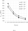
- the optimization of the radius r of the root 15 of the thread also makes it possible to participate in the reduction of the tensile stresses in the first member, as illustrated in the graphs of the figure 2 And 3 .
- FIG. 2 illustrates, for a zirconia caseback assembled with a stainless steel caseband comprising a standardized thread (ISO standard), the impact of the thread root radius on the stress undergone by the caseback threading, for different caseback thread angles.
- ISO standard standardized thread
- the first thread is connected to a bearing surface 5 via a connection fillet 13 having a radius greater than 0.4 times the pitch p of the first thread or greater than 0.8 times the pitch p of the first thread.
- This bearing surface extends radially outwards from the first thread and is intended to bear against a second surface 25 provided on the second timepiece.
- a gasket can be arranged between these two surfaces in order to provide a seal between the two members.
- the connecting fillet 13 is part of a groove, that is a cavity which has two groove walls and a groove bottom, and which ensures the connection between the support plane 5 and the first thread 11.
- a first groove wall can have a straight, curved or a combination of the two.
- the curvature can be defined by a groove radius 18a.
- Side bearing surface 5 the groove wall can have a straight axial section, curved or a combination of both.
- the curvature can be defined by a groove radius 18b.
- the bottom of the groove may have a point axial section, that is to say its axial section may be the point of intersection of the axial sections of the two groove walls.
- the bottom of the groove may be more extensive as shown in the figure 1 where two curved portions 18a and 18b are connected by a straight section portion.
- the first member also undergoes tensile stresses in the vicinity of this groove.
- the first metal members For components of the watch case type, typically for back-middle assemblies, the first metal members have groove radii on the thread side 18a and on the bearing surface side 18b of between 0.06 mm and 0.15 mm. Nominally, they are 0.05 mm.
- the groove radii on the thread 18a side and the support plane 18b side can be identical or different.
- connection angle between the groove and the bearing surface can be straight, acute or obtuse, with or without stitching in the material.
- connection between the groove and the bearing surface can be flat or recessed without affecting the tensile strength of the groove.
- the second thread 21 is preferably standardized.
- the second thread may be a standardized thread according to an ISO standard or according to an NIHS standard or according to a UN standard or according to a BSPT standard or according to an NPT standard or according to an NPTF standard or according to a DIN standard or according to an MJ standard. or according to a UNJ standard or according to a Whitworth profile.
- the first thread is an external or external thread, that is to say that it is made on a projecting surface, for example on a surface of a shaft.
- the second thread is an internal or internal thread, that is to say it is made on a recessed surface, for example on a surface of a bore.
- the first member is a bottom made of fragile material, in particular ceramic or sapphire or zirconia or glass, the first thread of which is subjected to tensile stresses.
- the back is assembled to a second member which is a middle part.
- This middle part is made of a more ductile material, in particular a metallic material or a metallic alloy.
- the invention can be transposed to any other type of screwing where a first member made of fragile material, in particular ceramic or sapphire or zirconia or glass, cooperates with a second member made of a more ductile material, in particular a metallic material or metal alloy, to make an assembly.
- the invention can also be transposed to any other type of screwing where a first member made of fragile material, in particular ceramic or sapphire or zirconia or glass, cooperates with a second member made of fragile material, in particular ceramic or sapphire or zirconia or glass, to make an assembly.
- the first and second members are screwed together so that they are mechanically constrained, the member constituting the screw being for example mechanically constrained in traction.
- charts make it possible to determine the limit value to adopt before damage of the screw-nut couple for predetermined dimensions in a given material and in a given normative reference frame. These charts do not exist for material pairs involving metal alloys and fragile materials such as ceramic, sapphire, zirconia or glass.
- the seizing threshold of a pair of materials is defined by the value of the contact pressure at which material is transferred from one surface to the other. There is a seizure threshold for each pair of materials. In addition to the surface condition, this threshold depends on the chemical and/or metallurgical nature of each of the two materials in contact.
- seizing can occur in two stages: micro-seizing, followed, if necessary, by total seizing.
- Micro-seizing appears when the tension no longer increases linearly but in stages while the tightening torque increases. These are, for example, micro-welds caused then broken by the tightening torque applied as and when they occur (“stick-slip” phenomenon). A relative rotation remains possible between the elements but the tightening is disturbed. This phenomenon can be localized.
- micro-seizing increases with the increase in the tightening torque until total seizing. When there is total seizure, all rotation is blocked.
- a prestressed threaded assembly remains removable as long as no seizing occurs between the members after tightening. This implies that to guarantee the disassembly of a threaded assembly, certain precautions are necessary, among other things to avoid any micro-seizing during initial tightening, to avoid any corrosion during service and to maintain a correct coefficient of friction during the life of the assembly.
- Stainless steel, aluminum and titanium threads are particularly prone to galling.
- stainless steel assemblies are generally treated, for example with a lubricant or an “anti-seize” coating. These treatments are likely to be degraded over time.
- a ceramic member for example made of zirconia, according to the invention has a lower probability of seizing than a metal member which it replaces.
- a zirconia component with a tightening torque of 5 N.m, no seizing or deformation was observed, even without treatment of the metal part.
- the system also supports higher tightening torques without seizing. For example, a torque of 10 N.m was applied to a zirconia caseback according to the invention, assembled on a stainless steel caseband, without initiating seizing or deformation of the components, even without treatment of the metal part.
- the thread may be a ceramized metal thread, that is to say a thread whose thread surfaces consist of a ceramic coating.
- the ceramization can be obtained by thermal spraying of a ceramic, by surface treatment, by heat treatment or by any other suitable technique.
- the invention makes it possible to minimize the risks of cracking or chipping of the ceramic layer as well as those of seizing of the assembly.
- the base material is, for example, stainless steel, titanium, etc.
- the ceramic layer is for example in oxidized ceramic (zirconia, alumina, aluminum titanate, etc.) or in non-oxidized ceramic such as a nitride or a carbide (aluminum nitride, silicon nitride, silicon carbide, tungsten carbide, etc). '
- bottoms in fragile materials or in metal alloy having the same geometries or substantially the same geometries and which can be interchanged to cooperate with the same middle part, in particular the same metal middle part. Furthermore, these bottoms can be mounted without the need to modify the production tools or after-sales service for the assembly/dismantling of the bottom, regardless of the material in which the bottom is made.
- a waterproof wristwatch case comprising a bottom made of fragile material, in particular ceramic, in sapphire, zirconia or glass, replacing a metal back without adapting the metal middle.
- the invention it is possible to modify the thread of the bottom made of fragile material in order to preserve its integrity during screwing, in a tightening and use condition identical to that of a metal bottom.
- the seizing problems encountered with metal heads are avoided, even with higher tightening torques than those usually used with metal alloy heads.
- a thread of a member made of fragile type material so that the thread resists the same ranges of stresses as a metal part that the member replaces and so that the thread is compatible with standard threads, for example threads according to Swiss watchmaking standards (NIHS).
- NIHS Swiss watchmaking standards
- This design thus advantageously allows the easy replacement of a metal bottom by a ceramic bottom without the need to modify the design of the metal part that receives it and/or the bottom assembly/disassembly tools, while guaranteeing proper sealing, secure assembly and minimizing the risk of seizing.
- the external and internal threads are machined according to the same class with the same tolerance, in order to be compatible and to maximize the contact surface between the external and internal threads.
- the flanks of the internal thread and the flanks of the external thread are in contact over the largest possible surface, the flanks being as "flat” as possible.
- the first and second members are advantageously linked by a threaded connection, or assembled to each other by screwing.
- a timepiece comprises such an assembly.
Landscapes
- Engineering & Computer Science (AREA)
- Physics & Mathematics (AREA)
- General Physics & Mathematics (AREA)
- General Engineering & Computer Science (AREA)
- Mechanical Engineering (AREA)
- Manufacturing & Machinery (AREA)
- Adornments (AREA)
- Connection Of Plates (AREA)
Claims (12)
- Uhrenorgan (10), das eine erste Achse (A10) und ein erstes Gewinde (11), das eine Steigung (p) aufweist und dazu bestimmt ist, mit einem zweiten Gewinde (21), das an einem zweiten Uhrenorgan (20) vorgesehen ist, zusammenzuwirken, beinhaltet, wobei das erste Gewinde so konfiguriert ist, dass sich ein Kontaktbereich (C) zwischen dem ersten Gewinde und dem zweiten Gewinde über weniger als 50 % der Höhe (h) der Gewindeelemente des zweiten Gewindes erstreckt, oder so konfiguriert ist, dass sich der Kontaktbereich (C) zwischen dem ersten Gewinde und dem zweiten Gewinde über weniger als das 0,3-fache der Steigung (p) erstreckt, wobei die Erstreckung (e) des Kontaktbereichs von dem Boden (15) der Gewindeelemente des ersten Gewindes aus radial zu der ersten Achse (A10) gemessen wird.
- Uhrenorgan nach dem vorhergehenden Anspruch, dadurch gekennzeichnet, dass das erste Gewinde (11) einen ersten Flankenwinkel (12) aufweist, dass das zweite Gewinde (21) einen zweiten Flankenwinkel (22) aufweist und dass der Wert des ersten Flankenwinkels (12) um 2 bis 4 Grad größer ist als der Wert des zweiten Flankenwinkels (22) .
- Uhrenorgan nach Anspruch 1 oder 2, dadurch gekennzeichnet, dass die Höhe der Gewindeelemente des ersten Gewindes kleiner als das 0,3-fache der Steigung ist.
- Uhrenorgan nach einem der vorhergehenden Ansprüche, dadurch gekennzeichnet, dass das erste Gewinde einen Gewindegrundradius (15) aufweist, der größer als das 0,2-fache der Steigung des ersten Gewindes ist oder größer als das 0,4-fache der Steigung des ersten Gewindes ist.
- Uhrenorgan nach einem der vorhergehenden Ansprüche, dadurch gekennzeichnet, dass das erste Gewinde mittels einer Anschlussausrundung (13), die einen Radius (18b) aufweist, der größer als das 0,4-fache der Steigung des ersten Gewindes oder größer als das 0,8-fache der Steigung des ersten Gewindes ist, an eine Auflagefläche (5) angeschlossen ist.
- Uhrenorgan nach einem der vorhergehenden Ansprüche, dadurch gekennzeichnet, dass das zweite Gewinde ein normiertes Gewinde ist, insbesondere ein nach einer ISO-Norm oder nach einer NIHS-Norm oder nach einer UN-Norm oder nach einer BSPT-Norm oder nach einer NPT-Norm oder nach einer NPTF-Norm oder nach einer DIN-Norm oder nach einer MJ-Norm oder nach einer UNJ-Norm oder nach einem Whitworth-Profil normiertes Gewinde.
- Uhrenorgan nach einem der vorhergehenden Ansprüche, dadurch gekennzeichnet, dass das Uhrenorgan (10) aus einem Material spröden Typs, insbesondere aus Keramik oder aus Saphir oder aus Zirconiumdioxid oder aus Glas, hergestellt ist oder dass das Uhrenorgan (10) hauptsächlich aus einem metallischen Material oder einer Metalllegierung hergestellt ist und das erste Gewinde Oberflächen aufweist, die aus einer Beschichtung aus einem Material spröden Typs, insbesondere aus Keramik, bestehen.
- Uhrenorgan (10) nach einem der vorhergehenden Ansprüche, dadurch gekennzeichnet, dass:das Uhrenorgan (10) ein Boden ist und das zweite Uhrenorgan (20) ein Mittelteil oder ein Innenmittelteil ist; oderdas Uhrenorgan (10) ein Mittelteil oder ein Innenmittelteil ist und das zweite Uhrenorgan (20) ein Boden ist; oderdas Uhrenorgan (10) ein Mittelteil ist und das zweite Uhrenorgan (20) ein Innenmittelteil ist; oderdas Uhrenorgan (10) ein Innenmittelteil und das zweite Uhrenorgan (20) ein Mittelteil ist; oderdas Uhrenorgan (10) eine Krone ist und das zweite Uhrenorgan (20) eine Kronenröhre ist; oderdas Uhrenorgan (10) eine Kronenröhre ist und das zweite Uhrenorgan (20) eine Krone ist; oderdas Uhrenorgan (10) eine Krone ist und das zweite Uhrenorgan (20) eine Kronenkappe ist; oderdas Uhrenorgan (10) eine Ventilröhre ist und das zweite Uhrenorgan (20) ein Ventil ist; oderdas Uhrenorgan (10) eine Korrektorröhre ist und das zweite Uhrenorgan (20) ein Korrektor ist; oderdas Uhrenorgan (10) eine Abdeckung ist und das zweite Uhrenorgan (20) eine Krone oder eine Kronenröhre oder ein Schaft ist; oderdas Uhrenorgan (10) eine Schraube ist und das zweite Uhrenorgan (20) ein Glied eines Armbands ist.
- Gehäuse (100) einer Uhr (200), das ein erstes Uhrenorgan (10) nach einem der Ansprüche 1 bis 8 und ein anderes Uhrenorgan (20), insbesondere ein anderes Uhrenorgan nach einem der Ansprüche 1 bis 8 und/oder ein anderes Uhrenorgan, das auf oder in das erste Organ geschraubt ist, beinhaltet.
- Gehäuse (100) einer Uhr (200), das ein Mittelteil (20), insbesondere ein Mittelteil aus Metall, das das zweite Uhrenorgan (20) nach einem der Ansprüche 1 bis 8 bildet, und einen Boden (10), der das Uhrenorgan (10) nach einem der Ansprüche 1 bis 8 bildet, beinhaltet.
- Gehäuse (100) einer Uhr (200), das einen Boden (20), insbesondere einen Boden aus Metall, der das zweite Uhrenorgan (20) nach einem der Ansprüche 1 bis 8 bildet, und ein Mittelteil (10), das das erste Uhrenorgan (10) nach einem der Ansprüche 1 bis 8 bildet, beinhaltet.
- Uhr (200), insbesondere eine Armbanduhr, insbesondere eine Armbanduhr mit einem Uhrenarmband, die ein Uhrenorgan nach einem der Ansprüche 1 bis 8 und/oder ein Gehäuse (100) einer Uhr (200) nach einem der Ansprüche 9 bis 11 beinhaltet.
Priority Applications (4)
| Application Number | Priority Date | Filing Date | Title |
|---|---|---|---|
| EP20185189.6A EP3936732B1 (de) | 2020-07-10 | 2020-07-10 | Uhrorgan mit gewinde |
| JP2021108481A JP7737831B2 (ja) | 2020-07-10 | 2021-06-30 | ねじ付時計部材 |
| CN202110773687.2A CN113985716B (zh) | 2020-07-10 | 2021-07-08 | 螺纹钟表构件 |
| US17/372,033 US11880169B2 (en) | 2020-07-10 | 2021-07-09 | Threaded timepiece member |
Applications Claiming Priority (1)
| Application Number | Priority Date | Filing Date | Title |
|---|---|---|---|
| EP20185189.6A EP3936732B1 (de) | 2020-07-10 | 2020-07-10 | Uhrorgan mit gewinde |
Publications (2)
| Publication Number | Publication Date |
|---|---|
| EP3936732A1 EP3936732A1 (de) | 2022-01-12 |
| EP3936732B1 true EP3936732B1 (de) | 2023-03-15 |
Family
ID=71575146
Family Applications (1)
| Application Number | Title | Priority Date | Filing Date |
|---|---|---|---|
| EP20185189.6A Active EP3936732B1 (de) | 2020-07-10 | 2020-07-10 | Uhrorgan mit gewinde |
Country Status (4)
| Country | Link |
|---|---|
| US (1) | US11880169B2 (de) |
| EP (1) | EP3936732B1 (de) |
| JP (1) | JP7737831B2 (de) |
| CN (1) | CN113985716B (de) |
Citations (1)
| Publication number | Priority date | Publication date | Assignee | Title |
|---|---|---|---|---|
| EP0575277B1 (de) * | 1992-06-17 | 1997-05-14 | AEROSPATIALE Société Nationale Industrielle | Schraubsystem aus Verbundmaterial, dass aus einer mit feuerfesten Fibern verstärkten Keramikmatrix besteht |
Family Cites Families (27)
| Publication number | Priority date | Publication date | Assignee | Title |
|---|---|---|---|---|
| US403511A (en) * | 1889-05-21 | William w | ||
| US378959A (en) * | 1888-03-06 | Petee heney | ||
| US1661232A (en) * | 1925-10-30 | 1928-03-06 | Hans Wilsdorf | Keyless watch |
| US1910908A (en) * | 1931-03-31 | 1933-05-23 | Wadsworth Watch Case Co | Watchcase |
| US2482317A (en) * | 1944-06-28 | 1949-09-20 | Rolex Watch Co Ltd | Tight winding device for watches |
| CH486059A (fr) | 1966-09-23 | 1970-02-15 | Boites De Montres F Kuhn S A F | Boîte de montre étanche |
| CH1179667A4 (de) * | 1967-08-22 | 1971-06-15 | ||
| CH1359773A4 (fr) | 1973-09-21 | 1976-07-30 | Rolex Montres | Boîte de montre |
| JPS6042393Y2 (ja) * | 1980-01-24 | 1985-12-26 | シチズン時計株式会社 | クオ−ツ腕時計の防水リユウズ装置 |
| CH680825B5 (de) | 1991-06-27 | 1993-05-28 | Rado Montres Sa | |
| CH682199B5 (fr) * | 1992-02-07 | 1994-02-15 | Smh Management Services Ag | Soupape de sécurité pour pièce d'horlogérie de plongeur. |
| US5580199A (en) * | 1993-06-29 | 1996-12-03 | Kabushiki Kaisha Suzuki Rashi Seisakusho | Fastening screw |
| JP2989129B2 (ja) * | 1995-10-09 | 1999-12-13 | イワタボルト株式会社 | 雄ねじ |
| DE10055995B4 (de) * | 2000-11-11 | 2005-10-27 | Junghans Uhren Gmbh | Armbanduhr mit Notrufsender |
| US7698989B2 (en) * | 2002-07-04 | 2010-04-20 | Luk Fahrzeug-Hydraulik Gmbh & Co. Kg | Reciprocating piston machine |
| EP1564413A4 (de) * | 2002-11-22 | 2006-02-08 | Nobuyuki Sugimura | Ein innen- und aussengewinde verwendender druckspeicher |
| JP4506218B2 (ja) * | 2003-03-31 | 2010-07-21 | セイコーエプソン株式会社 | ボタン構造、およびこれを備えた携帯機器 |
| EP1775050A1 (de) * | 2005-10-14 | 2007-04-18 | Eric Bouille | Anordnung aus Uhrengehäusen |
| DE07405187T1 (de) | 2007-07-02 | 2008-12-04 | Rolex Sa | Wasserdichtes Armbanduhrgehäuse |
| ES2525817T3 (es) * | 2007-08-13 | 2014-12-30 | Research Engineering&Amp;Manufacturing, Inc. | Elemento de fijación que forma una rosca |
| EP2533111B1 (de) * | 2011-06-08 | 2015-08-12 | Omega SA | Vorrichtung und Verfahren zum Befestigen eines Armbanduhrelements mit regulierbarer Winkelausrichtung |
| CH706003A2 (fr) | 2011-11-15 | 2013-06-14 | Dc Swiss Sa | Système d'assemblage fileté autobloquant. |
| CH708049A2 (fr) * | 2013-05-14 | 2014-11-14 | Safelock Sa | Système d'assemblage fileté autobloquant. |
| FR3027649A1 (fr) * | 2014-10-24 | 2016-04-29 | Vallourec Oil & Gas France | Protecteur de connexion d'un composant tubulaire |
| EP3276432B1 (de) * | 2016-07-26 | 2020-03-25 | Omega SA | Untereinheit zur verkleidung einer uhr, armbanduhr oder eines schmuckstücks |
| JP7042748B2 (ja) * | 2016-10-28 | 2022-03-28 | 株式会社トープラ | おねじ及びねじ締結構造 |
| CN106438657A (zh) * | 2016-12-07 | 2017-02-22 | 石文祥 | 螺距过盈配合螺纹、螺纹连接件以及修正螺纹加工工具 |
-
2020
- 2020-07-10 EP EP20185189.6A patent/EP3936732B1/de active Active
-
2021
- 2021-06-30 JP JP2021108481A patent/JP7737831B2/ja active Active
- 2021-07-08 CN CN202110773687.2A patent/CN113985716B/zh active Active
- 2021-07-09 US US17/372,033 patent/US11880169B2/en active Active
Patent Citations (1)
| Publication number | Priority date | Publication date | Assignee | Title |
|---|---|---|---|---|
| EP0575277B1 (de) * | 1992-06-17 | 1997-05-14 | AEROSPATIALE Société Nationale Industrielle | Schraubsystem aus Verbundmaterial, dass aus einer mit feuerfesten Fibern verstärkten Keramikmatrix besteht |
Also Published As
| Publication number | Publication date |
|---|---|
| EP3936732A1 (de) | 2022-01-12 |
| US20220066393A1 (en) | 2022-03-03 |
| CN113985716B (zh) | 2025-05-23 |
| JP7737831B2 (ja) | 2025-09-11 |
| US11880169B2 (en) | 2024-01-23 |
| CN113985716A (zh) | 2022-01-28 |
| JP2022016326A (ja) | 2022-01-21 |
Similar Documents
| Publication | Publication Date | Title |
|---|---|---|
| CA2870858C (fr) | Element de fixation de pieces d'un assemblage | |
| EP2813715B1 (de) | Selbstblockierendes Verschraubungssystem | |
| BE897900A (fr) | Liaison entre un premier élément et un alésage formé dans un second élément. | |
| FR2503805A1 (fr) | Attache en deux parties pour fixer plusieurs pieces ensemble | |
| FR2931911A1 (fr) | Systeme et procede d'assemblage par brides entre deux pieces tournantes | |
| EP2344802B1 (de) | Bauteil für das bohren und den betrieb von kohlenwasserstoffbohrlöcher | |
| EP2462829B1 (de) | Armband mit Gelenkgliedern, und Verwendung dieses Armbands | |
| FR3060701A1 (fr) | Joint filete pour composant tubulaire | |
| EP3936732B1 (de) | Uhrorgan mit gewinde | |
| EP2780605B2 (de) | Selbstverriegelndes befestigungssystem mit schraubgewinden | |
| EP3257393B1 (de) | Schraube zum zusammenbau von zwei uhrenkomponenten | |
| EP3483667A1 (de) | Befestigungssystem eines uhrwerks in einem armbanduhrengehäuse | |
| EP3483668A1 (de) | Befestigungssystem eines uhrwerks in einem armbanduhrengehäuse | |
| EP1431597A1 (de) | Herstellungsverfahren eines metallischen Kugelgelenks | |
| CH719969A1 (fr) | Dispositif de fixation pour des composants horlogers ou joaillers | |
| CH717211A2 (fr) | Couronne pour boîte de pièce d'horlogerie, tige pour mouvement horloger et pièce d'horlogerie. | |
| FR2955632A1 (fr) | Boulon de traction a double dispositif d'arret | |
| EP3570116A1 (de) | Uhrverkleidungskomponente, die mittel zur drehblockierung umfasst | |
| EP4532967B1 (de) | Rohrförmiges bauteil mit einem gewindeanschlusselement | |
| EP3052992A1 (de) | Hauptfeder für ein hauptfass zur minimierung des trommelverschleisses | |
| EP4703596A1 (de) | Vorgespannte schraubanordnung mit verbessertem design zur erhaltung der leistung bei kryogenen temperaturen | |
| WO2022184993A1 (fr) | Elément tubulaire fileté à segment | |
| EP3742236A1 (de) | Uhrvorrichtung, die eine erste komponente umfasst, die auf einer zweiten komponente durch plastische verformung fixiert ist | |
| CH708814A2 (fr) | Ancre d'horlogerie à cornes aux rayons d'intrados et d'extrados différents. | |
| FR2910801A1 (fr) | Dispositif d'osteosynthese comprenant un support avec orifice taraude associe a un appui en tronc de sphere,pour la reception d'une tige d'ancrage |
Legal Events
| Date | Code | Title | Description |
|---|---|---|---|
| PUAI | Public reference made under article 153(3) epc to a published international application that has entered the european phase |
Free format text: ORIGINAL CODE: 0009012 |
|
| STAA | Information on the status of an ep patent application or granted ep patent |
Free format text: STATUS: THE APPLICATION HAS BEEN PUBLISHED |
|
| AK | Designated contracting states |
Kind code of ref document: A1 Designated state(s): AL AT BE BG CH CY CZ DE DK EE ES FI FR GB GR HR HU IE IS IT LI LT LU LV MC MK MT NL NO PL PT RO RS SE SI SK SM TR |
|
| B565 | Issuance of search results under rule 164(2) epc |
Effective date: 20210113 |
|
| STAA | Information on the status of an ep patent application or granted ep patent |
Free format text: STATUS: REQUEST FOR EXAMINATION WAS MADE |
|
| 17P | Request for examination filed |
Effective date: 20220705 |
|
| RBV | Designated contracting states (corrected) |
Designated state(s): AL AT BE BG CH CY CZ DE DK EE ES FI FR GB GR HR HU IE IS IT LI LT LU LV MC MK MT NL NO PL PT RO RS SE SI SK SM TR |
|
| GRAP | Despatch of communication of intention to grant a patent |
Free format text: ORIGINAL CODE: EPIDOSNIGR1 |
|
| STAA | Information on the status of an ep patent application or granted ep patent |
Free format text: STATUS: GRANT OF PATENT IS INTENDED |
|
| INTG | Intention to grant announced |
Effective date: 20220922 |
|
| GRAS | Grant fee paid |
Free format text: ORIGINAL CODE: EPIDOSNIGR3 |
|
| GRAA | (expected) grant |
Free format text: ORIGINAL CODE: 0009210 |
|
| STAA | Information on the status of an ep patent application or granted ep patent |
Free format text: STATUS: THE PATENT HAS BEEN GRANTED |
|
| AK | Designated contracting states |
Kind code of ref document: B1 Designated state(s): AL AT BE BG CH CY CZ DE DK EE ES FI FR GB GR HR HU IE IS IT LI LT LU LV MC MK MT NL NO PL PT RO RS SE SI SK SM TR |
|
| REG | Reference to a national code |
Ref country code: CH Ref legal event code: EP Ref country code: GB Ref legal event code: FG4D Free format text: NOT ENGLISH |
|
| REG | Reference to a national code |
Ref country code: DE Ref legal event code: R096 Ref document number: 602020008821 Country of ref document: DE |
|
| REG | Reference to a national code |
Ref country code: IE Ref legal event code: FG4D Free format text: LANGUAGE OF EP DOCUMENT: FRENCH |
|
| REG | Reference to a national code |
Ref country code: AT Ref legal event code: REF Ref document number: 1554154 Country of ref document: AT Kind code of ref document: T Effective date: 20230415 |
|
| REG | Reference to a national code |
Ref country code: LT Ref legal event code: MG9D |
|
| P01 | Opt-out of the competence of the unified patent court (upc) registered |
Effective date: 20230529 |
|
| REG | Reference to a national code |
Ref country code: NL Ref legal event code: MP Effective date: 20230315 |
|
| PG25 | Lapsed in a contracting state [announced via postgrant information from national office to epo] |
Ref country code: RS Free format text: LAPSE BECAUSE OF FAILURE TO SUBMIT A TRANSLATION OF THE DESCRIPTION OR TO PAY THE FEE WITHIN THE PRESCRIBED TIME-LIMIT Effective date: 20230315 Ref country code: NO Free format text: LAPSE BECAUSE OF FAILURE TO SUBMIT A TRANSLATION OF THE DESCRIPTION OR TO PAY THE FEE WITHIN THE PRESCRIBED TIME-LIMIT Effective date: 20230615 Ref country code: LV Free format text: LAPSE BECAUSE OF FAILURE TO SUBMIT A TRANSLATION OF THE DESCRIPTION OR TO PAY THE FEE WITHIN THE PRESCRIBED TIME-LIMIT Effective date: 20230315 Ref country code: LT Free format text: LAPSE BECAUSE OF FAILURE TO SUBMIT A TRANSLATION OF THE DESCRIPTION OR TO PAY THE FEE WITHIN THE PRESCRIBED TIME-LIMIT Effective date: 20230315 Ref country code: HR Free format text: LAPSE BECAUSE OF FAILURE TO SUBMIT A TRANSLATION OF THE DESCRIPTION OR TO PAY THE FEE WITHIN THE PRESCRIBED TIME-LIMIT Effective date: 20230315 |
|
| REG | Reference to a national code |
Ref country code: AT Ref legal event code: MK05 Ref document number: 1554154 Country of ref document: AT Kind code of ref document: T Effective date: 20230315 |
|
| PG25 | Lapsed in a contracting state [announced via postgrant information from national office to epo] |
Ref country code: SE Free format text: LAPSE BECAUSE OF FAILURE TO SUBMIT A TRANSLATION OF THE DESCRIPTION OR TO PAY THE FEE WITHIN THE PRESCRIBED TIME-LIMIT Effective date: 20230315 Ref country code: NL Free format text: LAPSE BECAUSE OF FAILURE TO SUBMIT A TRANSLATION OF THE DESCRIPTION OR TO PAY THE FEE WITHIN THE PRESCRIBED TIME-LIMIT Effective date: 20230315 Ref country code: GR Free format text: LAPSE BECAUSE OF FAILURE TO SUBMIT A TRANSLATION OF THE DESCRIPTION OR TO PAY THE FEE WITHIN THE PRESCRIBED TIME-LIMIT Effective date: 20230616 Ref country code: FI Free format text: LAPSE BECAUSE OF FAILURE TO SUBMIT A TRANSLATION OF THE DESCRIPTION OR TO PAY THE FEE WITHIN THE PRESCRIBED TIME-LIMIT Effective date: 20230315 |
|
| PG25 | Lapsed in a contracting state [announced via postgrant information from national office to epo] |
Ref country code: SM Free format text: LAPSE BECAUSE OF FAILURE TO SUBMIT A TRANSLATION OF THE DESCRIPTION OR TO PAY THE FEE WITHIN THE PRESCRIBED TIME-LIMIT Effective date: 20230315 Ref country code: RO Free format text: LAPSE BECAUSE OF FAILURE TO SUBMIT A TRANSLATION OF THE DESCRIPTION OR TO PAY THE FEE WITHIN THE PRESCRIBED TIME-LIMIT Effective date: 20230315 Ref country code: PT Free format text: LAPSE BECAUSE OF FAILURE TO SUBMIT A TRANSLATION OF THE DESCRIPTION OR TO PAY THE FEE WITHIN THE PRESCRIBED TIME-LIMIT Effective date: 20230717 Ref country code: ES Free format text: LAPSE BECAUSE OF FAILURE TO SUBMIT A TRANSLATION OF THE DESCRIPTION OR TO PAY THE FEE WITHIN THE PRESCRIBED TIME-LIMIT Effective date: 20230315 Ref country code: EE Free format text: LAPSE BECAUSE OF FAILURE TO SUBMIT A TRANSLATION OF THE DESCRIPTION OR TO PAY THE FEE WITHIN THE PRESCRIBED TIME-LIMIT Effective date: 20230315 Ref country code: CZ Free format text: LAPSE BECAUSE OF FAILURE TO SUBMIT A TRANSLATION OF THE DESCRIPTION OR TO PAY THE FEE WITHIN THE PRESCRIBED TIME-LIMIT Effective date: 20230315 Ref country code: AT Free format text: LAPSE BECAUSE OF FAILURE TO SUBMIT A TRANSLATION OF THE DESCRIPTION OR TO PAY THE FEE WITHIN THE PRESCRIBED TIME-LIMIT Effective date: 20230315 |
|
| PG25 | Lapsed in a contracting state [announced via postgrant information from national office to epo] |
Ref country code: SK Free format text: LAPSE BECAUSE OF FAILURE TO SUBMIT A TRANSLATION OF THE DESCRIPTION OR TO PAY THE FEE WITHIN THE PRESCRIBED TIME-LIMIT Effective date: 20230315 Ref country code: PL Free format text: LAPSE BECAUSE OF FAILURE TO SUBMIT A TRANSLATION OF THE DESCRIPTION OR TO PAY THE FEE WITHIN THE PRESCRIBED TIME-LIMIT Effective date: 20230315 Ref country code: IS Free format text: LAPSE BECAUSE OF FAILURE TO SUBMIT A TRANSLATION OF THE DESCRIPTION OR TO PAY THE FEE WITHIN THE PRESCRIBED TIME-LIMIT Effective date: 20230715 |
|
| REG | Reference to a national code |
Ref country code: DE Ref legal event code: R097 Ref document number: 602020008821 Country of ref document: DE |
|
| PLBE | No opposition filed within time limit |
Free format text: ORIGINAL CODE: 0009261 |
|
| STAA | Information on the status of an ep patent application or granted ep patent |
Free format text: STATUS: NO OPPOSITION FILED WITHIN TIME LIMIT |
|
| PG25 | Lapsed in a contracting state [announced via postgrant information from national office to epo] |
Ref country code: SI Free format text: LAPSE BECAUSE OF FAILURE TO SUBMIT A TRANSLATION OF THE DESCRIPTION OR TO PAY THE FEE WITHIN THE PRESCRIBED TIME-LIMIT Effective date: 20230315 Ref country code: DK Free format text: LAPSE BECAUSE OF FAILURE TO SUBMIT A TRANSLATION OF THE DESCRIPTION OR TO PAY THE FEE WITHIN THE PRESCRIBED TIME-LIMIT Effective date: 20230315 |
|
| 26N | No opposition filed |
Effective date: 20231218 |
|
| PG25 | Lapsed in a contracting state [announced via postgrant information from national office to epo] |
Ref country code: MC Free format text: LAPSE BECAUSE OF FAILURE TO SUBMIT A TRANSLATION OF THE DESCRIPTION OR TO PAY THE FEE WITHIN THE PRESCRIBED TIME-LIMIT Effective date: 20230315 |
|
| PG25 | Lapsed in a contracting state [announced via postgrant information from national office to epo] |
Ref country code: MC Free format text: LAPSE BECAUSE OF FAILURE TO SUBMIT A TRANSLATION OF THE DESCRIPTION OR TO PAY THE FEE WITHIN THE PRESCRIBED TIME-LIMIT Effective date: 20230315 |
|
| REG | Reference to a national code |
Ref country code: BE Ref legal event code: MM Effective date: 20230731 |
|
| PG25 | Lapsed in a contracting state [announced via postgrant information from national office to epo] |
Ref country code: LU Free format text: LAPSE BECAUSE OF NON-PAYMENT OF DUE FEES Effective date: 20230710 |
|
| PG25 | Lapsed in a contracting state [announced via postgrant information from national office to epo] |
Ref country code: LU Free format text: LAPSE BECAUSE OF NON-PAYMENT OF DUE FEES Effective date: 20230710 |
|
| REG | Reference to a national code |
Ref country code: IE Ref legal event code: MM4A |
|
| PG25 | Lapsed in a contracting state [announced via postgrant information from national office to epo] |
Ref country code: IT Free format text: LAPSE BECAUSE OF FAILURE TO SUBMIT A TRANSLATION OF THE DESCRIPTION OR TO PAY THE FEE WITHIN THE PRESCRIBED TIME-LIMIT Effective date: 20230315 Ref country code: BE Free format text: LAPSE BECAUSE OF NON-PAYMENT OF DUE FEES Effective date: 20230731 |
|
| PG25 | Lapsed in a contracting state [announced via postgrant information from national office to epo] |
Ref country code: IE Free format text: LAPSE BECAUSE OF NON-PAYMENT OF DUE FEES Effective date: 20230710 |
|
| PG25 | Lapsed in a contracting state [announced via postgrant information from national office to epo] |
Ref country code: IE Free format text: LAPSE BECAUSE OF NON-PAYMENT OF DUE FEES Effective date: 20230710 |
|
| PG25 | Lapsed in a contracting state [announced via postgrant information from national office to epo] |
Ref country code: BG Free format text: LAPSE BECAUSE OF FAILURE TO SUBMIT A TRANSLATION OF THE DESCRIPTION OR TO PAY THE FEE WITHIN THE PRESCRIBED TIME-LIMIT Effective date: 20230315 |
|
| PG25 | Lapsed in a contracting state [announced via postgrant information from national office to epo] |
Ref country code: BG Free format text: LAPSE BECAUSE OF FAILURE TO SUBMIT A TRANSLATION OF THE DESCRIPTION OR TO PAY THE FEE WITHIN THE PRESCRIBED TIME-LIMIT Effective date: 20230315 |
|
| PG25 | Lapsed in a contracting state [announced via postgrant information from national office to epo] |
Ref country code: CY Free format text: LAPSE BECAUSE OF FAILURE TO SUBMIT A TRANSLATION OF THE DESCRIPTION OR TO PAY THE FEE WITHIN THE PRESCRIBED TIME-LIMIT; INVALID AB INITIO Effective date: 20200710 |
|
| PG25 | Lapsed in a contracting state [announced via postgrant information from national office to epo] |
Ref country code: HU Free format text: LAPSE BECAUSE OF FAILURE TO SUBMIT A TRANSLATION OF THE DESCRIPTION OR TO PAY THE FEE WITHIN THE PRESCRIBED TIME-LIMIT; INVALID AB INITIO Effective date: 20200710 |
|
| PGFP | Annual fee paid to national office [announced via postgrant information from national office to epo] |
Ref country code: DE Payment date: 20250711 Year of fee payment: 6 |
|
| PGFP | Annual fee paid to national office [announced via postgrant information from national office to epo] |
Ref country code: GB Payment date: 20250723 Year of fee payment: 6 |
|
| PGFP | Annual fee paid to national office [announced via postgrant information from national office to epo] |
Ref country code: FR Payment date: 20250730 Year of fee payment: 6 |
|
| PGFP | Annual fee paid to national office [announced via postgrant information from national office to epo] |
Ref country code: CH Payment date: 20250801 Year of fee payment: 6 |
|
| PG25 | Lapsed in a contracting state [announced via postgrant information from national office to epo] |
Ref country code: TR Free format text: LAPSE BECAUSE OF FAILURE TO SUBMIT A TRANSLATION OF THE DESCRIPTION OR TO PAY THE FEE WITHIN THE PRESCRIBED TIME-LIMIT Effective date: 20230315 |