EP3938936B1 - Klonen der konfiguration einer sicherheitsvorrichtung - Google Patents
Klonen der konfiguration einer sicherheitsvorrichtung Download PDFInfo
- Publication number
- EP3938936B1 EP3938936B1 EP20773547.3A EP20773547A EP3938936B1 EP 3938936 B1 EP3938936 B1 EP 3938936B1 EP 20773547 A EP20773547 A EP 20773547A EP 3938936 B1 EP3938936 B1 EP 3938936B1
- Authority
- EP
- European Patent Office
- Prior art keywords
- sensor
- card
- password
- parameter set
- field
- Prior art date
- Legal status (The legal status is an assumption and is not a legal conclusion. Google has not performed a legal analysis and makes no representation as to the accuracy of the status listed.)
- Active
Links
Images



Classifications
-
- G—PHYSICS
- G06—COMPUTING OR CALCULATING; COUNTING
- G06F—ELECTRIC DIGITAL DATA PROCESSING
- G06F21/00—Security arrangements for protecting computers, components thereof, programs or data against unauthorised activity
- G06F21/70—Protecting specific internal or peripheral components, in which the protection of a component leads to protection of the entire computer
- G06F21/71—Protecting specific internal or peripheral components, in which the protection of a component leads to protection of the entire computer to assure secure computing or processing of information
- G06F21/73—Protecting specific internal or peripheral components, in which the protection of a component leads to protection of the entire computer to assure secure computing or processing of information by creating or determining hardware identification, e.g. serial numbers
-
- H—ELECTRICITY
- H04—ELECTRIC COMMUNICATION TECHNIQUE
- H04W—WIRELESS COMMUNICATION NETWORKS
- H04W4/00—Services specially adapted for wireless communication networks; Facilities therefor
- H04W4/30—Services specially adapted for particular environments, situations or purposes
- H04W4/38—Services specially adapted for particular environments, situations or purposes for collecting sensor information
-
- G—PHYSICS
- G06—COMPUTING OR CALCULATING; COUNTING
- G06F—ELECTRIC DIGITAL DATA PROCESSING
- G06F21/00—Security arrangements for protecting computers, components thereof, programs or data against unauthorised activity
- G06F21/30—Authentication, i.e. establishing the identity or authorisation of security principals
- G06F21/44—Program or device authentication
-
- H—ELECTRICITY
- H04—ELECTRIC COMMUNICATION TECHNIQUE
- H04W—WIRELESS COMMUNICATION NETWORKS
- H04W12/00—Security arrangements; Authentication; Protecting privacy or anonymity
- H04W12/06—Authentication
-
- H—ELECTRICITY
- H04—ELECTRIC COMMUNICATION TECHNIQUE
- H04W—WIRELESS COMMUNICATION NETWORKS
- H04W12/00—Security arrangements; Authentication; Protecting privacy or anonymity
- H04W12/10—Integrity
-
- H—ELECTRICITY
- H04—ELECTRIC COMMUNICATION TECHNIQUE
- H04W—WIRELESS COMMUNICATION NETWORKS
- H04W4/00—Services specially adapted for wireless communication networks; Facilities therefor
- H04W4/50—Service provisioning or reconfiguring
-
- H—ELECTRICITY
- H04—ELECTRIC COMMUNICATION TECHNIQUE
- H04W—WIRELESS COMMUNICATION NETWORKS
- H04W12/00—Security arrangements; Authentication; Protecting privacy or anonymity
- H04W12/60—Context-dependent security
- H04W12/65—Environment-dependent, e.g. using captured environmental data
Definitions
- This application relates to automated systems, and in particular, to configuring sensors of automated or robotic devices, as well as related systems and methods.
- An automated system may include mobile and/or stationary robots used to perform various tasks for industrial automation.
- Mobile robots include, for example, automated guide vehicles, automated intelligent vehicles, etc. which assist with routine, labor intensive material handling tasks.
- Stationary robots include, for example, robotic arms which typically comprise a plurality of links connected by one or more joints. The one or more joints of a robotic arm are driven by various types of actuators (e.g., electric motors, hydraulics, etc.) to control articulation of the robotic arm to position an end effector that is configured to perform a task.
- actuators e.g., electric motors, hydraulics, etc.
- Automated systems may utilize one or more safety sensors or devices that detect, measure, analyze, and process various changes that occur on productions sites, such as changes in position, length, height, displacement, and appearance. Configuring a safety sensor having a large and complex set of configurable parameters may pose challenges in some instances. Additionally, an automated system may comprise a large number of safety sensors needing to programmed identically.
- US 2008/281953 A1 discloses devices and methods for managing a communications network include using USB keys to provision and management components in the network by having the network component establish a connection to a network administrator device, such as a laptop, PDA, or desktop workstation.
- a first USB key is used to provision a network component so that it has the necessary security information to interact with a second USB key, used to enable actual management of the component.
- EP1499067A1 discloses a communication system, an information processing apparatus and method which enable communication setting to be performed through easy operations.
- An access point has communication setting information for allowing wireless communication to be performed between a terminal apparatus and the access point.
- the communication setting information is supplied to a tag through contactless communication at close range between an IC tag reader/writer and the tag and stored therein.
- the terminal apparatus performs setting for communicating with the access point based on the stored communication setting information and then performs wireless communication with the access point.
- the invention is defined by the appended claims.
- This application describes a system configured to facilitate safety sensor configuration.
- the system may comprise an automated device comprising a safety sensor configured to perform a safety feature based on one or more sensor parameters, wherein a sensor serial number and a sensor password are linked with the sensor a removable memory card configured to be accessed by the automated device and having stored thereon a parameter set, and a field for containing an identifier; a processor coupled to the sensor; and a memory storing computer-executable instructions to cause the processor to determine, based on the identifier in the field or based on whether the field is blank or contains the identifier, whether the parameter set is unique to the device or not; when the processor determines that the parameter set is not unique to the device based on the identifier or the field being blank, the instructions cause the processor to: determine whether a password stored on the card matches the sensor password; and in response to the password stored on the card matching the sensor password, configure the sensor to perform the safety feature based on the parameter set from the
- An automated system may include one or more mobile robots and/or one or more stationary robots for handling various tasks.
- fleets of mobile robots also called automated guided vehicles (AGVs)
- AGVs automated guided vehicles
- Stationary robots may include robotic arms configured for specific tasks (e.g., assembly operations, diecasting, fettling machines, gas welding, arc welding, and pick and place work).
- Examples of stationary robots include but are not limited to: (i) Cartesian robots whose axes form a cylindrical coordinate system; (ii) cylindrical robots whose axes form a cylindrical coordinate system; (iii) polar robots whose axes form a polar coordinate system; (iv) selective compliance assembly robot arm (SCARA) robots featuring two parallel rotary joints to provide compliance in a plane; (v) articulated robots whose arm has at least three rotary joints; (vi) parallel robots whose arms have concurrent prismatic or rotary joints; and (vii) anthropomorphic robots shaped in a way that resembles a human hand, i.e., having independent fingers and thumbs.
- SCARA selective compliance assembly robot arm
- Safety sensors/components may be used with mobile and/or stationary robots (referred to collectively herein as "robots") for safety countermeasures in equipment and facilities.
- Safety sensors may be used for shut-out detection of mechanical guards, checking intrusion into hazardous areas, and building safety circuits. Examples of safety sensors included but are not limited to: safety laser scanners; safety light curtains, single-beam safety sensors, limit switches, stop switches, a safety relays, and safety network controller.
- Safety laser scanners or other systems for sensing the presence of an object and/or for measuring a distance to an object can be used in various applications, such as for guarding hazardous equipment (e.g., industrial machinery), for surveying, for security systems, for robot vision, robot guidance or pathfinding, etc.
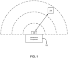
- FIG. 1 shows a laser scanner 100 configured for guarding hazardous equipment 102 (e.g., such as industrial machinery).
- guarding hazardous equipment 102 e.g., such as industrial machinery.
- a laser scanner 100 can emit a pulse of light and receive light reflected from an object 104, which can be measured and used to determine that the object 104 is present.
- the laser scanner 100 can send pulses of light in multiple directions so that the direction to the object can be determined.
- the laser scanner 100 can step light pulses across an angular field of view, such as at sub-degree increments, although other increments or other configurations could be used, depending on the application.
- the laser scanner 100 can determine a distance to the object 104, such as by determining a time-of-flight for the light to travel to the object and then back to the laser scanner 100.
- the distance to the object can be 1 ⁇ 2 ⁇ c ⁇ t, where c is the speed of light, and t is the time-of-flight.
- the location of the object 104 can be determined.
- Action can be taken in response to the determination of the location, direction, and/or distance of the object.
- the hazardous equipment 102 can be stopped if an object 104 (e.g., a person) comes within a threshold distance, or an alarm or warning can be issued, etc.
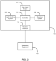
- FIG. 2 is a block diagram showing components of an example embodiment of laser scanner 100.
- the laser scanner 100 can have a light emitting system 106, which can be configured to emit light, such as by producing pulses of light.
- the light emitting system 106 can have a laser, such as a pulse laser that is configured to output discrete laser pulses.
- the duration of the light pulses (e.g., the laser pulse width) can also affect the resolution of the distance determination. For example, in some cases, increasing the actual sampling rate can have diminishing returns for increasing the distance resolution if the light pulses are not fast enough.
- Faster lasers e.g., that produce laser pulses with shorter pulse widths, can be expensive.
- Some embodiments disclosed herein can relate to upsampling to effectively increase the sampling rate to increase the resolution of the distance measurement while using cost effective lasers and other components.
- the laser scanner 100 can have a detection system 108 that can be configured to receive light of the laser pulses that is reflected from the object 104 back to the laser scanner 100.
- the laser scanner 100 can have a controller 110 configured to control operations of the laser scanner 100, as described herein.
- the controller 110 can include one or more hardware processors, and can execute instructions that are stored in computer-readable memory (e.g., in a non-transitory computer readable medium).
- the laser scanner 100 can have a machine interface 114, which can output instructions to corresponding hazardous equipment 102 (e.g., industrial machinery). For example, the laser scanner can stop the machinery or move the machinery to a safety configuration if an object (e.g., a person) is detected at a specified location or distance, etc. Other output signals can also be provided, such as for warning or alarms or data logging, etc.
- the laser scanner 100 can have input/output features 112.
- user input elements e.g., one or more buttons, dials, switches, microphone, etc.
- User output elements e.g., one or more lights, speakers, display, printer, etc.
- user input and output elements can be combined, such as a touchscreen display.
- the input and output elements 112 can be used to configure, operate, and/or troubleshoot the laser scanner 100.
- the output elements 112 can provide direction, distance, and/or location information regarding an object.
- the laser scanner 100 can have multiple lights that can be selectively illuminated to indicate a direction of an object.
- the laser scanner 100 can output a first color of light (e.g., green) for a safe condition (e.g., in which no object is determined to be in a dangerous location or range) and can output a second color of light (e.g., red) for a danger condition (e.g., in which an object is determined to be in a dangerous location or range).
- a first color of light e.g., green
- a second color of light e.g., red
- a danger condition e.g., in which an object is determined to be in a dangerous location or range.
- a safety sensor e.g., the laser scanner 100
- a large number of safety sensors that have the same large and complex set of configurable parameters may need to be programmed identically, for example, when commissioning a fleet of AGVs.
- the systems and methods described herein provide users with a fast and efficient way to program one or more safety sensors, as well as sensors generally, that does not involve individually connecting, configuring, and confirming each of the one or more parameters in each single sensor.
- safety sensor(s) and/or automated device(s) that comprise one or more safety sensors may be configured/programmed to perform a safety feature/task by utilizing portable memory device(s), e.g., removable memory card(s), while still preventing the unauthorized reconfiguration of safety sensor(s) already configured to perform the safety feature.
- portable memory device(s) e.g., removable memory card(s)
- a computer 202 may be used to pre-program a full configuration of the one or more parameters into multiple memory cards 204, 206, 208 using a card reader/writer, e.g., a built-in card reader of the computer 202.
- the memory cards 204, 206, and 208 are installed into corresponding safety sensors 214, 216, and 218, respectively.
- Each safety sensor is configured to receive/accept its corresponding memory card, access the corresponding memory card, and utilize the information on the corresponding memory card to set/program/configure one or parameters for the safety sensor. As the sensors 214, 216, 218 are tested and debugged, steps one and two above may be repeated until the commissioning of the sensor fleet is completed.
- each of the sensors 214, 216, 218 must be able to accept a cloned memory card 204, 206, 208 at any point in time, both physically (the slot being accessible) and logically, i.e., the new configuration of the sensor parameters from the cloned memory card 204, 206, 208 being accepted by the software of (i) the safety sensor 214, 216, 218 or (ii) an automated device that comprises the safety sensor 214, 216, 218.
- a unit e.g., a sensor or a device that includes the sensor
- a unit e.g., a sensor or a device that includes the sensor
- the removal or swapping of flash memory cards In general terms, nobody without the right access level (e.g., knowledge of a password) would be able to modify the configuration in the unit.
- each sensor has its own sensor serial number and a sensor password required to modify its safety configuration.
- a removable memory card used with such a sensor may contain or have stored thereon the following example fields: (i) a serial number of the sensor to which card belongs; (ii) a password for reconfiguration access to the sensor (e.g., an encrypted password such that the actual password cannot be learned from reading the memory card file system and then used with the regular configuration software to reconfigure the unit); (iii) a configuration parameter set for the sensor; and (iv) a cyclic redundancy check (CRC) covering fields (i)-(iii) to ensure data integrity.
- CRC cyclic redundancy check
- the cloning process on the computer 202 may involve filling up the fields on the memory card, but leaving the serial number field blank as a "cloning" flag.
- the password for each unit within which each card is installed is needed to prove that correct access level is met (i.e., that the configuring/reconfiguring of unit based on a parameter set stored on the card is authorized).
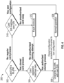
- FIG. 4 is a flowchart illustrating an example method 300 implemented by a processor (or controller) of a unit that comprises a safety sensor.
- the method 300 begins at decision block 302, at which the processor determines whether a serial number field of the card is blank. If the serial number field of the card is blank, then the method 300 proceeds with a cloned card process by moving to decision block 304. If the serial number field is blank, it means the card comes from a cloning process. The password field of the card then needs to be checked against an actual unit password to ensure appropriate access level to reconfigure that unit was used during the cloning. At decision block 304, the processor determines whether a password stored on the card matches a sensor password of the sensor.
- the processor determines that the cloning process is authorized, and the method 300 proceeds to block 306.
- the blank serial number field is overwritten with a serial number of the sensor, and the cloned configuration of the parameters is accepted as the sensor's own configuration of the parameters.
- the method 300 advances from block 306 to block 308 where the sensor proceeds with normal operation, e.g., performing a safety feature based on the parameters. In other words, the sensor serial number is used to overwrite the card blank serial number, and the cloned configuration is accepted to be used in the future.
- the processor determines that the cloning attempt is unauthorized, and the method 300 proceeds to block 312 where the unit can transition into a safe lockout state.
- the method 300 proceeds to a regular card process by moving to decision block 310.
- decision block 310 if the serial number from the card matches the sensor serial number, the card is recognized as pre-existing and its safety configuration is used. If the serial number from the card does not match the sensor serial number, then the method 300 proceeds to block 312 where the unit can transition into a safe lockout state.
- Unauthorized configuration attempts where either (i) a card is from a different unit (based on the serial numbers not matching) or (ii) the passwords do not match may be detected so the unit can transition into a safe lockout state. The same is true if the CRC check over the data is not valid due to data corruption or unauthorized data manipulation.
- a method 400 400 by a safety unit that comprises a safety sensor, the sensor configured to perform a safety feature based on one or more sensor parameters.
- the method 400 may involve, at block 410, accessing a memory card, the card having stored thereon a password, a parameter set, and a flag indicative of whether the parameter set is unique to the sensor.
- the method 400 may involve, at block 420, determining, based on the flag, that the parameter set is not unique to the sensor.
- the method 400 may involve, at block 430, determining whether the password stored on the card matches a sensor password of the sensor.
- the method 400 may involve, at block 440, in response to the password stored on the card matching the sensor password, writing a sensor serial number of the sensor onto the card.
- the flag may comprise a serial number field of the card.
- block 420 may involve determining that the serial number field of the card is blank.
- the method 400 may further involve, in response to the password stored on the card matching the sensor password, writing the sensor serial number into the serial number field of the card.
- the configuring of the sensor may comprise updating the one or more sensor parameters based on the parameter set.
- the configuring of the sensor may comprise copying the parameter set from the card into the memory.
- the method 400 may further involve performing a CRC on at least one of the flag, the password, and the parameter set stored on the card to ensure data integrity.
- the method 400 may further involve, in response to the password stored on the card matching the sensor password, deleting the password stored on the card. In another aspect, the method 400 may further involve, in response to the password stored on the card not matching the sensor password, stopping the configuration of the sensor based on the parameter set to prevent an unauthorized configuring of the sensor. In yet another aspect, the memory may be part of the sensor.
- the safety sensor may comprise a safety laser scanner, and the parameter set may comprise one or more of response time, operating mode, protection boundary definition, zone switching parameters, object resolution, and input and output configuration.
- the device may comprise an automated guide vehicle. In further related aspects, the device may comprise a robotic arm.
- the safety sensor may comprise one of a safety light curtain, a single-beam safety sensor, a limit switch, a stop switch, a safety relay, and a safety network controller.
- the password may comprise an encrypted password.
- the parameter set may be shared among a fleet of devices, each of the devices configured to receive a corresponding card having stored thereon a corresponding password and the parameter set.
- the method 500 may involve, at block 510, accessing a memory card, the card having stored thereon a parameter set and a flag indicative of whether the parameter set is unique to the sensor.
- the method 500 may involve, at block 520, determining, based on the flag, that the parameter set is unique to the sensor.
- the method 500 may involve, at block 530, determining whether information in the flag corresponds to a sensor serial number of the sensor.
- the method 500 may involve, at block 540, in response to the information in the flag corresponding to the sensor serial number, configuring the sensor to perform the safety feature based on the parameter set.
- the method 500 may further involve, in response to the information in the flag not corresponding to the sensor serial number, preventing the configuration of the sensor based on the parameter set.
- the method 500 may further involve, performing a CRC on at least one of the flag and the parameter set stored on the card.
- top, bottom, side, up, down, inward, outward, etc. are generally used with reference to the orientation shown in the figures and are not intended to be limiting.
- the top surface described above can refer to a bottom surface or a side surface.
- features described on the top surface may be included on a bottom surface, a side surface, or any other surface.
Landscapes
- Engineering & Computer Science (AREA)
- Computer Security & Cryptography (AREA)
- Theoretical Computer Science (AREA)
- Physics & Mathematics (AREA)
- Computer Hardware Design (AREA)
- Signal Processing (AREA)
- Computer Networks & Wireless Communication (AREA)
- Software Systems (AREA)
- General Engineering & Computer Science (AREA)
- General Physics & Mathematics (AREA)
- Mathematical Physics (AREA)
- Traffic Control Systems (AREA)
- Safety Devices In Control Systems (AREA)
- Manipulator (AREA)
- Alarm Systems (AREA)
Claims (11)
- System, das dazu konfiguriert ist, eine Konfiguration eines Sicherheitssensors zu erleichtern, wobei das System Folgendes umfasst:eine automatisierte Vorrichtung, die einen Sicherheitssensor (214; 216; 218) umfasst, der dazu konfiguriert ist, eine Sicherheitsfunktion auf Grundlage eines oder mehrerer Sensorparameter auszuführen, wobei eine Sensorseriennummer und ein Sensorkennwort mit dem Sensor (214; 216; 218) verknüpft sind;eine entfernbare Speicherkarte (204; 206; 208), die für einen Zugriff durch die automatisierte Vorrichtung konfiguriert ist und auf der ein Parametersatz und ein Feld zum Enthalten einer Kennung gespeichert sind;einen Prozessor, der an den Sensor (214; 216; 218) gekoppelt ist; undeinen Speicher, auf dem computerausführbare Anweisungen gespeichert sind, die den Prozessor dazu veranlassen, auf Grundlage der Kennung in dem Feld oder auf Grundlage davon, ob das Feld leer ist oder die Kennung enthält, zu bestimmen, ob der Parametersatz für die Vorrichtung eindeutig ist oder nicht;wenn der Prozessor auf Grundlage der Kennung oder davon, dass das Feld leer ist, bestimmt, dass der Parametersatz nicht für die Vorrichtung eindeutig ist, veranlassen die Anweisungen den Prozessor zu Folgendem:Bestimmen, ob ein auf der Karte (204; 206; 208) gespeichertes Kennwort mit dem Sensorkennwort übereinstimmt; undals Reaktion darauf, dass das auf der Karte (204; 206; 208) gespeicherte Kennwort mit dem Sensorkennwort übereinstimmt, Konfigurieren des Sensors (214; 216; 218), um die Sicherheitsfunktion auf Grundlage des Parametersatzes von der Karte (204; 206; 208) auszuführen; undwenn der Prozessor auf Grundlage der Kennung bestimmt, dass der Parametersatz für die Vorrichtung eindeutig ist, veranlassen die Anweisungen den Prozessor zu Folgendem:Bestimmen, ob die Kennung in dem Feld der Sensorseriennummer entspricht; undals Reaktion darauf, dass die Kennung in dem Feld der Sensorseriennummer entspricht, Konfigurieren des Sensors (214; 216; 218), um die Sicherheitsfunktion auf Grundlage des Parametersatzes auszuführen, ohne Ausführen einer Bestimmung unter Verwendung des Sensorkennworts.
- System nach Anspruch 1, wobei das Feld ein Seriennummernfeld der Karte (204; 206; 208) umfasst.
- System nach Anspruch 2, wobei das Bestimmen, dass der Parametersatz nicht für die Vorrichtung eindeutig ist, Bestimmen, dass das Seriennummernfeld der Karte (204; 206; 208) leer ist, umfasst.
- System nach Anspruch 2, wobei der Speicher ferner computerausführbare Anweisungen umfasst, um den Prozessor zu Folgendem zu veranlassen:
als Reaktion darauf, dass das auf der Karte (204; 206; 208) gespeicherte Kennwort mit dem Sensorkennwort übereinstimmt, Schreiben der Sensorseriennummer in das Seriennummernfeld der Karte (204; 206; 208). - System nach Anspruch 1, wobei das Konfigurieren des Sensors (214; 216; 218) Aktualisieren des einen oder der mehreren Sensorparameter auf Grundlage des Parametersatzes umfasst.
- System nach Anspruch 1, wobei das Konfigurieren des Sensors (214; 216; 218) Kopieren des Parametersatzes von der Karte (204; 206; 208) auf den Speicher umfasst.
- System nach Anspruch 1, wobei der Speicher ferner computerausführbare Anweisungen umfasst, um den Prozessor zu Folgendem zu veranlassen:
Ausführen einer zyklischen Redundanzprüfung (CRC) für mindestens eines von dem Feld, dem Kennwort und dem Parametersatz, der auf der Karte (204; 206; 208) gespeichert ist, um die Datenintegrität sicherzustellen. - System nach Anspruch 1, wobei der Speicher ferner computerausführbare Anweisungen umfasst, um den Prozessor zu Folgendem zu veranlassen:
als Reaktion darauf, dass das auf der Karte (204; 206; 208) gespeicherte Kennwort mit dem Sensorkennwort übereinstimmt, Löschen des auf der Karte (204; 206; 208) gespeicherten Kennworts. - System nach Anspruch 1, wobei der Speicher ferner computerausführbare Anweisungen umfasst, um den Prozessor zu Folgendem zu veranlassen:
als Reaktion darauf, dass das auf der Karte (204; 206; 208) gespeicherte Kennwort nicht mit dem Sensorkennwort übereinstimmt, Anhalten der Konfiguration des Sensors (214; 216; 218) auf Grundlage des Parametersatzes, um ein nicht autorisiertes Konfigurieren des Sensors (214; 216; 218) zu verhindern. - System nach Anspruch 1, wobei der Speicher Teil des Sensors (214; 216; 218) ist.
- Durch einen Sicherheitssensor (214; 216; 218) betreibbares Verfahren, wobei der Sensor (214; 216; 218) dazu konfiguriert ist, eine Sicherheitsfunktion auf Grundlage eines oder mehrerer Sensorparameter auszuführen, wobei das Verfahren Folgendes umfasst:Zugreifen auf eine Speicherkarte (204; 206; 208), wobei auf der Karte (204; 206; 208) ein Parametersatz und ein Feld zum Enthalten einer Kennung gespeichert sind; undBestimmen, ob der Parametersatz für den Sensor (214; 216; 218) eindeutig ist oder nicht, auf Grundlage der Kennung in dem Feld oder auf Grundlage davon, ob das Feld leer ist oder die Kennung enthält;wenn auf Grundlage der Kennung oder davon, dass das Feld leer ist, bestimmt wird, dass der Parametersatz für den Sensor (214; 216; 218) nicht eindeutig ist, umfasst das Verfahren ferner Folgendes:Bestimmen, ob ein auf der Karte (204; 206; 208) gespeichertes Kennwort mit einem Sensorkennwort des Sensors (214; 216; 218) übereinstimmt; undals Reaktion darauf, dass das auf der Karte (204; 206; 208) gespeicherte Kennwort mit dem Sensorkennwort übereinstimmt, Schreiben einer Sensorseriennummer des Sensors (214; 216; 218) auf die Karte (204; 206; 208) undwenn auf Grundlage der Kennung bestimmt wird, dass der Parametersatz für den Sensor (214; 216; 218) eindeutig ist, umfasst das Verfahren ferner Folgendes:Bestimmen, ob die Kennung in dem Feld einer Sensorseriennummer des Sensors entspricht; undals Reaktion darauf, dass die Kennung in dem Feld der Sensorseriennummer entspricht, Konfigurieren des Sensors (214; 216; 218), um die Sicherheitsfunktion auf Grundlage des Parametersatz auszuführen, ohne Ausführen einer Bestimmung unter Verwendung des Sensorkennworts.
Applications Claiming Priority (2)
| Application Number | Priority Date | Filing Date | Title |
|---|---|---|---|
| US201962819406P | 2019-03-15 | 2019-03-15 | |
| PCT/US2020/020220 WO2020190473A1 (en) | 2019-03-15 | 2020-02-27 | Safety device configuration cloning |
Publications (3)
| Publication Number | Publication Date |
|---|---|
| EP3938936A1 EP3938936A1 (de) | 2022-01-19 |
| EP3938936A4 EP3938936A4 (de) | 2022-11-02 |
| EP3938936B1 true EP3938936B1 (de) | 2024-05-29 |
Family
ID=72520385
Family Applications (1)
| Application Number | Title | Priority Date | Filing Date |
|---|---|---|---|
| EP20773547.3A Active EP3938936B1 (de) | 2019-03-15 | 2020-02-27 | Klonen der konfiguration einer sicherheitsvorrichtung |
Country Status (5)
| Country | Link |
|---|---|
| US (1) | US12008148B2 (de) |
| EP (1) | EP3938936B1 (de) |
| JP (1) | JP7231057B2 (de) |
| CN (1) | CN113574918B (de) |
| WO (1) | WO2020190473A1 (de) |
Family Cites Families (22)
| Publication number | Priority date | Publication date | Assignee | Title |
|---|---|---|---|---|
| US6308099B1 (en) * | 1998-11-13 | 2001-10-23 | Intermedics Inc. | Implantable device and programmer system which permits multiple programmers |
| US6257486B1 (en) | 1998-11-23 | 2001-07-10 | Cardis Research & Development Ltd. | Smart card pin system, card, and reader |
| JP3748106B2 (ja) | 2002-04-25 | 2006-02-22 | ソニー株式会社 | 通信システム、情報処理装置および方法、記録媒体、並びにプログラム |
| US20030218533A1 (en) * | 2002-05-22 | 2003-11-27 | Flick Kenneth E. | Door access control system and associated methods |
| JP2004205723A (ja) | 2002-12-25 | 2004-07-22 | Toshiba Corp | デジタル情報記録装置、デジタル情報再生装置、デジタル情報記録再生装置、デジタル情報記録方法、デジタル情報再生方法及びデジタル情報記録再生方法 |
| US20050198233A1 (en) | 2004-01-07 | 2005-09-08 | Microsoft Corporation | Configuring network settings of thin client devices using portable storage media |
| US7546357B2 (en) * | 2004-01-07 | 2009-06-09 | Microsoft Corporation | Configuring network settings using portable storage media |
| JP3724493B2 (ja) * | 2004-03-15 | 2005-12-07 | オムロン株式会社 | 侵入者検知装置、侵入者威嚇装置、および車両用侵入者威嚇装置 |
| JP2005267163A (ja) | 2004-03-18 | 2005-09-29 | Toshiba Corp | メモリカード装置 |
| US8214885B2 (en) | 2007-05-07 | 2012-07-03 | Mocana Corporation | Managing network components using USB keys |
| US20100217428A1 (en) | 2009-02-23 | 2010-08-26 | Provo Craft And Novelty, Inc. | System for Controlling an Electronic Cutting Machine |
| JP2012108639A (ja) | 2010-11-16 | 2012-06-07 | Emiko Makita | リムーバブル記憶メディアの閲覧・視聴システム |
| WO2012068329A1 (en) | 2010-11-17 | 2012-05-24 | Omron Scientific Technologies, Inc. | A method and apparatus for monitoring zones |
| JP2012203490A (ja) | 2011-03-24 | 2012-10-22 | Mitene Internet Co Ltd | 情報処理装置およびデジタルフォトフレーム |
| JP5934977B2 (ja) | 2012-04-06 | 2016-06-15 | 株式会社ユピテル | 電子機器、記憶媒体及びプログラム |
| WO2014144628A2 (en) * | 2013-03-15 | 2014-09-18 | Master Lock Company | Cameras and networked security systems and methods |
| US9230137B2 (en) * | 2013-05-30 | 2016-01-05 | Dell Products, L.P. | Secure original equipment manufacturer (OEM) identifier for OEM devices |
| JP2015080494A (ja) * | 2013-10-21 | 2015-04-27 | テルモ株式会社 | 電気刺激装置 |
| CN103647648B (zh) * | 2013-12-10 | 2017-01-18 | 飞天诚信科技股份有限公司 | 一种安全通讯的方法 |
| JP7024190B2 (ja) * | 2017-03-03 | 2022-02-24 | オムロン株式会社 | ワイヤレスセンサシステムおよび通信方法 |
| US10951411B2 (en) * | 2017-08-23 | 2021-03-16 | Semiconductor Components Industries, Llc | Methods and apparatus for a password-protected integrated circuit |
| AU2018448130B2 (en) * | 2018-11-01 | 2025-04-10 | Fts Forest Technology Systems Ltd. | Multi-level authentication for shared device |
-
2020
- 2020-02-27 JP JP2021555330A patent/JP7231057B2/ja active Active
- 2020-02-27 US US17/593,216 patent/US12008148B2/en active Active
- 2020-02-27 WO PCT/US2020/020220 patent/WO2020190473A1/en not_active Ceased
- 2020-02-27 CN CN202080020898.2A patent/CN113574918B/zh active Active
- 2020-02-27 EP EP20773547.3A patent/EP3938936B1/de active Active
Also Published As
| Publication number | Publication date |
|---|---|
| JP7231057B2 (ja) | 2023-03-01 |
| WO2020190473A1 (en) | 2020-09-24 |
| EP3938936A4 (de) | 2022-11-02 |
| CN113574918A (zh) | 2021-10-29 |
| EP3938936A1 (de) | 2022-01-19 |
| US12008148B2 (en) | 2024-06-11 |
| US20220180002A1 (en) | 2022-06-09 |
| CN113574918B (zh) | 2025-01-07 |
| JP2022525871A (ja) | 2022-05-20 |
Similar Documents
| Publication | Publication Date | Title |
|---|---|---|
| EP2728516B1 (de) | Funkfrequenzidentifikation für Sicherheitsanwendungen | |
| JP7122776B2 (ja) | 作業空間安全監視および機器制御 | |
| US11396099B2 (en) | Safe operation of machinery using potential occupancy envelopes | |
| US10832548B2 (en) | Advanced industrial safety notification systems | |
| JP7299642B2 (ja) | 自動的センサ位置合わせおよび構成のためのシステムおよび方法 | |
| EP1817141B1 (de) | Industrielles robotersystem | |
| JP4560547B2 (ja) | 作業者安全管理システム | |
| CN111176224A (zh) | 使用数字孪生的工业安全监视配置 | |
| CN111693050A (zh) | 基于建筑信息模型的室内中大型机器人导航方法 | |
| US10549424B2 (en) | Setting device and setting system for configuring settings for a plurality of machines | |
| CN114310865B (zh) | 为机器区域配置可视化设备 | |
| CN110221581A (zh) | 工业控制网络监测装置和方法 | |
| KR102177711B1 (ko) | 충돌 감지 센서 및 이를 구비하는 로봇 | |
| EP0292857A1 (de) | Arbeitsvorgang-Steuerungssystem | |
| EP3938936B1 (de) | Klonen der konfiguration einer sicherheitsvorrichtung | |
| JPH0248400B2 (de) | ||
| Srikaanth et al. | An Approach to Ensure the Safety of Industry 4.0 Mobile Robots | |
| CN112789570A (zh) | 用于输入工作区域的方法和机器人系统 | |
| CN111590574B (zh) | 一种高智能机器人防盗方法及系统 | |
| Norton et al. | A standard test method for evaluating navigation and obstacle avoidance capabilities of AGVs and AMRs | |
| Geretti et al. | Process-driven collision prediction in human-robot work environments | |
| JPS6151204A (ja) | ロボツトの動作空間識別システム | |
| CN110722566A (zh) | 多关节机器人的全自动工艺流程平台开发方法及系统 | |
| US20240391104A1 (en) | Methods of Handling Safety of Industrial Robot, Control Systems, and Robot System | |
| KR100374391B1 (ko) | 자동화시스템을 위한 제어와 시뮬레이션의 통합제어장치및 그것의 운영방법 |
Legal Events
| Date | Code | Title | Description |
|---|---|---|---|
| STAA | Information on the status of an ep patent application or granted ep patent |
Free format text: STATUS: THE INTERNATIONAL PUBLICATION HAS BEEN MADE |
|
| PUAI | Public reference made under article 153(3) epc to a published international application that has entered the european phase |
Free format text: ORIGINAL CODE: 0009012 |
|
| STAA | Information on the status of an ep patent application or granted ep patent |
Free format text: STATUS: REQUEST FOR EXAMINATION WAS MADE |
|
| 17P | Request for examination filed |
Effective date: 20210902 |
|
| AK | Designated contracting states |
Kind code of ref document: A1 Designated state(s): AL AT BE BG CH CY CZ DE DK EE ES FI FR GB GR HR HU IE IS IT LI LT LU LV MC MK MT NL NO PL PT RO RS SE SI SK SM TR |
|
| DAV | Request for validation of the european patent (deleted) | ||
| DAX | Request for extension of the european patent (deleted) | ||
| A4 | Supplementary search report drawn up and despatched |
Effective date: 20220929 |
|
| RIC1 | Information provided on ipc code assigned before grant |
Ipc: H04W 12/10 20210101ALI20220923BHEP Ipc: H04W 4/50 20180101ALI20220923BHEP Ipc: H04W 4/38 20180101ALI20220923BHEP Ipc: H04W 12/06 20210101ALI20220923BHEP Ipc: G06F 21/82 20130101ALI20220923BHEP Ipc: G06F 21/71 20130101ALI20220923BHEP Ipc: G06F 21/44 20130101AFI20220923BHEP |
|
| GRAP | Despatch of communication of intention to grant a patent |
Free format text: ORIGINAL CODE: EPIDOSNIGR1 |
|
| STAA | Information on the status of an ep patent application or granted ep patent |
Free format text: STATUS: GRANT OF PATENT IS INTENDED |
|
| INTG | Intention to grant announced |
Effective date: 20240102 |
|
| GRAS | Grant fee paid |
Free format text: ORIGINAL CODE: EPIDOSNIGR3 |
|
| GRAA | (expected) grant |
Free format text: ORIGINAL CODE: 0009210 |
|
| STAA | Information on the status of an ep patent application or granted ep patent |
Free format text: STATUS: THE PATENT HAS BEEN GRANTED |
|
| AK | Designated contracting states |
Kind code of ref document: B1 Designated state(s): AL AT BE BG CH CY CZ DE DK EE ES FI FR GB GR HR HU IE IS IT LI LT LU LV MC MK MT NL NO PL PT RO RS SE SI SK SM TR |
|
| REG | Reference to a national code |
Ref country code: CH Ref legal event code: EP |
|
| REG | Reference to a national code |
Ref country code: IE Ref legal event code: FG4D |
|
| REG | Reference to a national code |
Ref country code: DE Ref legal event code: R096 Ref document number: 602020031693 Country of ref document: DE |
|
| REG | Reference to a national code |
Ref country code: LT Ref legal event code: MG9D |
|
| REG | Reference to a national code |
Ref country code: NL Ref legal event code: MP Effective date: 20240529 |
|
| PG25 | Lapsed in a contracting state [announced via postgrant information from national office to epo] |
Ref country code: IS Free format text: LAPSE BECAUSE OF FAILURE TO SUBMIT A TRANSLATION OF THE DESCRIPTION OR TO PAY THE FEE WITHIN THE PRESCRIBED TIME-LIMIT Effective date: 20240929 |
|
| PG25 | Lapsed in a contracting state [announced via postgrant information from national office to epo] |
Ref country code: BG Free format text: LAPSE BECAUSE OF FAILURE TO SUBMIT A TRANSLATION OF THE DESCRIPTION OR TO PAY THE FEE WITHIN THE PRESCRIBED TIME-LIMIT Effective date: 20240529 |
|
| PG25 | Lapsed in a contracting state [announced via postgrant information from national office to epo] |
Ref country code: HR Free format text: LAPSE BECAUSE OF FAILURE TO SUBMIT A TRANSLATION OF THE DESCRIPTION OR TO PAY THE FEE WITHIN THE PRESCRIBED TIME-LIMIT Effective date: 20240529 Ref country code: FI Free format text: LAPSE BECAUSE OF FAILURE TO SUBMIT A TRANSLATION OF THE DESCRIPTION OR TO PAY THE FEE WITHIN THE PRESCRIBED TIME-LIMIT Effective date: 20240529 |
|
| PG25 | Lapsed in a contracting state [announced via postgrant information from national office to epo] |
Ref country code: GR Free format text: LAPSE BECAUSE OF FAILURE TO SUBMIT A TRANSLATION OF THE DESCRIPTION OR TO PAY THE FEE WITHIN THE PRESCRIBED TIME-LIMIT Effective date: 20240830 |
|
| REG | Reference to a national code |
Ref country code: AT Ref legal event code: MK05 Ref document number: 1691228 Country of ref document: AT Kind code of ref document: T Effective date: 20240529 |
|
| PG25 | Lapsed in a contracting state [announced via postgrant information from national office to epo] |
Ref country code: ES Free format text: LAPSE BECAUSE OF FAILURE TO SUBMIT A TRANSLATION OF THE DESCRIPTION OR TO PAY THE FEE WITHIN THE PRESCRIBED TIME-LIMIT Effective date: 20240529 |
|
| PG25 | Lapsed in a contracting state [announced via postgrant information from national office to epo] |
Ref country code: AT Free format text: LAPSE BECAUSE OF FAILURE TO SUBMIT A TRANSLATION OF THE DESCRIPTION OR TO PAY THE FEE WITHIN THE PRESCRIBED TIME-LIMIT Effective date: 20240529 |
|
| PG25 | Lapsed in a contracting state [announced via postgrant information from national office to epo] |
Ref country code: PL Free format text: LAPSE BECAUSE OF FAILURE TO SUBMIT A TRANSLATION OF THE DESCRIPTION OR TO PAY THE FEE WITHIN THE PRESCRIBED TIME-LIMIT Effective date: 20240529 |
|
| PG25 | Lapsed in a contracting state [announced via postgrant information from national office to epo] |
Ref country code: LV Free format text: LAPSE BECAUSE OF FAILURE TO SUBMIT A TRANSLATION OF THE DESCRIPTION OR TO PAY THE FEE WITHIN THE PRESCRIBED TIME-LIMIT Effective date: 20240529 |
|
| PG25 | Lapsed in a contracting state [announced via postgrant information from national office to epo] |
Ref country code: PL Free format text: LAPSE BECAUSE OF FAILURE TO SUBMIT A TRANSLATION OF THE DESCRIPTION OR TO PAY THE FEE WITHIN THE PRESCRIBED TIME-LIMIT Effective date: 20240529 Ref country code: NO Free format text: LAPSE BECAUSE OF FAILURE TO SUBMIT A TRANSLATION OF THE DESCRIPTION OR TO PAY THE FEE WITHIN THE PRESCRIBED TIME-LIMIT Effective date: 20240829 Ref country code: LV Free format text: LAPSE BECAUSE OF FAILURE TO SUBMIT A TRANSLATION OF THE DESCRIPTION OR TO PAY THE FEE WITHIN THE PRESCRIBED TIME-LIMIT Effective date: 20240529 Ref country code: IS Free format text: LAPSE BECAUSE OF FAILURE TO SUBMIT A TRANSLATION OF THE DESCRIPTION OR TO PAY THE FEE WITHIN THE PRESCRIBED TIME-LIMIT Effective date: 20240929 Ref country code: HR Free format text: LAPSE BECAUSE OF FAILURE TO SUBMIT A TRANSLATION OF THE DESCRIPTION OR TO PAY THE FEE WITHIN THE PRESCRIBED TIME-LIMIT Effective date: 20240529 Ref country code: GR Free format text: LAPSE BECAUSE OF FAILURE TO SUBMIT A TRANSLATION OF THE DESCRIPTION OR TO PAY THE FEE WITHIN THE PRESCRIBED TIME-LIMIT Effective date: 20240830 Ref country code: FI Free format text: LAPSE BECAUSE OF FAILURE TO SUBMIT A TRANSLATION OF THE DESCRIPTION OR TO PAY THE FEE WITHIN THE PRESCRIBED TIME-LIMIT Effective date: 20240529 Ref country code: ES Free format text: LAPSE BECAUSE OF FAILURE TO SUBMIT A TRANSLATION OF THE DESCRIPTION OR TO PAY THE FEE WITHIN THE PRESCRIBED TIME-LIMIT Effective date: 20240529 Ref country code: BG Free format text: LAPSE BECAUSE OF FAILURE TO SUBMIT A TRANSLATION OF THE DESCRIPTION OR TO PAY THE FEE WITHIN THE PRESCRIBED TIME-LIMIT Effective date: 20240529 Ref country code: AT Free format text: LAPSE BECAUSE OF FAILURE TO SUBMIT A TRANSLATION OF THE DESCRIPTION OR TO PAY THE FEE WITHIN THE PRESCRIBED TIME-LIMIT Effective date: 20240529 Ref country code: RS Free format text: LAPSE BECAUSE OF FAILURE TO SUBMIT A TRANSLATION OF THE DESCRIPTION OR TO PAY THE FEE WITHIN THE PRESCRIBED TIME-LIMIT Effective date: 20240829 |
|
| PG25 | Lapsed in a contracting state [announced via postgrant information from national office to epo] |
Ref country code: NL Free format text: LAPSE BECAUSE OF FAILURE TO SUBMIT A TRANSLATION OF THE DESCRIPTION OR TO PAY THE FEE WITHIN THE PRESCRIBED TIME-LIMIT Effective date: 20240529 |
|
| PG25 | Lapsed in a contracting state [announced via postgrant information from national office to epo] |
Ref country code: NL Free format text: LAPSE BECAUSE OF FAILURE TO SUBMIT A TRANSLATION OF THE DESCRIPTION OR TO PAY THE FEE WITHIN THE PRESCRIBED TIME-LIMIT Effective date: 20240529 |
|
| PG25 | Lapsed in a contracting state [announced via postgrant information from national office to epo] |
Ref country code: DK Free format text: LAPSE BECAUSE OF FAILURE TO SUBMIT A TRANSLATION OF THE DESCRIPTION OR TO PAY THE FEE WITHIN THE PRESCRIBED TIME-LIMIT Effective date: 20240529 |
|
| PG25 | Lapsed in a contracting state [announced via postgrant information from national office to epo] |
Ref country code: EE Free format text: LAPSE BECAUSE OF FAILURE TO SUBMIT A TRANSLATION OF THE DESCRIPTION OR TO PAY THE FEE WITHIN THE PRESCRIBED TIME-LIMIT Effective date: 20240529 |
|
| PG25 | Lapsed in a contracting state [announced via postgrant information from national office to epo] |
Ref country code: CZ Free format text: LAPSE BECAUSE OF FAILURE TO SUBMIT A TRANSLATION OF THE DESCRIPTION OR TO PAY THE FEE WITHIN THE PRESCRIBED TIME-LIMIT Effective date: 20240529 |
|
| PG25 | Lapsed in a contracting state [announced via postgrant information from national office to epo] |
Ref country code: RO Free format text: LAPSE BECAUSE OF FAILURE TO SUBMIT A TRANSLATION OF THE DESCRIPTION OR TO PAY THE FEE WITHIN THE PRESCRIBED TIME-LIMIT Effective date: 20240529 Ref country code: SK Free format text: LAPSE BECAUSE OF FAILURE TO SUBMIT A TRANSLATION OF THE DESCRIPTION OR TO PAY THE FEE WITHIN THE PRESCRIBED TIME-LIMIT Effective date: 20240529 |
|
| PG25 | Lapsed in a contracting state [announced via postgrant information from national office to epo] |
Ref country code: SM Free format text: LAPSE BECAUSE OF FAILURE TO SUBMIT A TRANSLATION OF THE DESCRIPTION OR TO PAY THE FEE WITHIN THE PRESCRIBED TIME-LIMIT Effective date: 20240529 |
|
| PG25 | Lapsed in a contracting state [announced via postgrant information from national office to epo] |
Ref country code: SM Free format text: LAPSE BECAUSE OF FAILURE TO SUBMIT A TRANSLATION OF THE DESCRIPTION OR TO PAY THE FEE WITHIN THE PRESCRIBED TIME-LIMIT Effective date: 20240529 Ref country code: SK Free format text: LAPSE BECAUSE OF FAILURE TO SUBMIT A TRANSLATION OF THE DESCRIPTION OR TO PAY THE FEE WITHIN THE PRESCRIBED TIME-LIMIT Effective date: 20240529 Ref country code: RO Free format text: LAPSE BECAUSE OF FAILURE TO SUBMIT A TRANSLATION OF THE DESCRIPTION OR TO PAY THE FEE WITHIN THE PRESCRIBED TIME-LIMIT Effective date: 20240529 Ref country code: EE Free format text: LAPSE BECAUSE OF FAILURE TO SUBMIT A TRANSLATION OF THE DESCRIPTION OR TO PAY THE FEE WITHIN THE PRESCRIBED TIME-LIMIT Effective date: 20240529 Ref country code: DK Free format text: LAPSE BECAUSE OF FAILURE TO SUBMIT A TRANSLATION OF THE DESCRIPTION OR TO PAY THE FEE WITHIN THE PRESCRIBED TIME-LIMIT Effective date: 20240529 Ref country code: CZ Free format text: LAPSE BECAUSE OF FAILURE TO SUBMIT A TRANSLATION OF THE DESCRIPTION OR TO PAY THE FEE WITHIN THE PRESCRIBED TIME-LIMIT Effective date: 20240529 |
|
| PG25 | Lapsed in a contracting state [announced via postgrant information from national office to epo] |
Ref country code: IT Free format text: LAPSE BECAUSE OF FAILURE TO SUBMIT A TRANSLATION OF THE DESCRIPTION OR TO PAY THE FEE WITHIN THE PRESCRIBED TIME-LIMIT Effective date: 20240529 |
|
| REG | Reference to a national code |
Ref country code: DE Ref legal event code: R097 Ref document number: 602020031693 Country of ref document: DE |
|
| PLBE | No opposition filed within time limit |
Free format text: ORIGINAL CODE: 0009261 |
|
| STAA | Information on the status of an ep patent application or granted ep patent |
Free format text: STATUS: NO OPPOSITION FILED WITHIN TIME LIMIT |
|
| PG25 | Lapsed in a contracting state [announced via postgrant information from national office to epo] |
Ref country code: SI Free format text: LAPSE BECAUSE OF FAILURE TO SUBMIT A TRANSLATION OF THE DESCRIPTION OR TO PAY THE FEE WITHIN THE PRESCRIBED TIME-LIMIT Effective date: 20240529 |
|
| 26N | No opposition filed |
Effective date: 20250303 |
|
| PG25 | Lapsed in a contracting state [announced via postgrant information from national office to epo] |
Ref country code: SE Free format text: LAPSE BECAUSE OF FAILURE TO SUBMIT A TRANSLATION OF THE DESCRIPTION OR TO PAY THE FEE WITHIN THE PRESCRIBED TIME-LIMIT Effective date: 20240529 |
|
| PG25 | Lapsed in a contracting state [announced via postgrant information from national office to epo] |
Ref country code: MC Free format text: LAPSE BECAUSE OF FAILURE TO SUBMIT A TRANSLATION OF THE DESCRIPTION OR TO PAY THE FEE WITHIN THE PRESCRIBED TIME-LIMIT Effective date: 20240529 |
|
| REG | Reference to a national code |
Ref country code: CH Ref legal event code: PL |
|
| PG25 | Lapsed in a contracting state [announced via postgrant information from national office to epo] |
Ref country code: LU Free format text: LAPSE BECAUSE OF NON-PAYMENT OF DUE FEES Effective date: 20250227 |
|
| PG25 | Lapsed in a contracting state [announced via postgrant information from national office to epo] |
Ref country code: CH Free format text: LAPSE BECAUSE OF NON-PAYMENT OF DUE FEES Effective date: 20250228 |
|
| GBPC | Gb: european patent ceased through non-payment of renewal fee |
Effective date: 20250227 |
|
| REG | Reference to a national code |
Ref country code: BE Ref legal event code: MM Effective date: 20250228 |
|
| PG25 | Lapsed in a contracting state [announced via postgrant information from national office to epo] |
Ref country code: GB Free format text: LAPSE BECAUSE OF NON-PAYMENT OF DUE FEES Effective date: 20250227 |
|
| PG25 | Lapsed in a contracting state [announced via postgrant information from national office to epo] |
Ref country code: FR Free format text: LAPSE BECAUSE OF NON-PAYMENT OF DUE FEES Effective date: 20250228 |
|
| PG25 | Lapsed in a contracting state [announced via postgrant information from national office to epo] |
Ref country code: BE Free format text: LAPSE BECAUSE OF NON-PAYMENT OF DUE FEES Effective date: 20250228 |
|
| PG25 | Lapsed in a contracting state [announced via postgrant information from national office to epo] |
Ref country code: IE Free format text: LAPSE BECAUSE OF NON-PAYMENT OF DUE FEES Effective date: 20250227 |
|
| PGFP | Annual fee paid to national office [announced via postgrant information from national office to epo] |
Ref country code: DE Payment date: 20260217 Year of fee payment: 7 |