EP3943016A1 - Mécanisme d'alignement de cartouche pour une utilisation avec des dispositifs chirurgicaux - Google Patents
Mécanisme d'alignement de cartouche pour une utilisation avec des dispositifs chirurgicaux Download PDFInfo
- Publication number
- EP3943016A1 EP3943016A1 EP21186599.3A EP21186599A EP3943016A1 EP 3943016 A1 EP3943016 A1 EP 3943016A1 EP 21186599 A EP21186599 A EP 21186599A EP 3943016 A1 EP3943016 A1 EP 3943016A1
- Authority
- EP
- European Patent Office
- Prior art keywords
- cartridge
- reloadable
- engagement portion
- orientation
- inner body
- Prior art date
- Legal status (The legal status is an assumption and is not a legal conclusion. Google has not performed a legal analysis and makes no representation as to the accuracy of the status listed.)
- Withdrawn
Links
- 230000007246 mechanism Effects 0.000 title claims abstract description 28
- 230000001154 acute effect Effects 0.000 claims description 4
- 230000013011 mating Effects 0.000 description 6
- 238000000034 method Methods 0.000 description 4
- 206010019909 Hernia Diseases 0.000 description 3
- 238000006073 displacement reaction Methods 0.000 description 3
- 238000012976 endoscopic surgical procedure Methods 0.000 description 3
- 230000007704 transition Effects 0.000 description 3
- 210000003815 abdominal wall Anatomy 0.000 description 2
- 230000008878 coupling Effects 0.000 description 2
- 238000010168 coupling process Methods 0.000 description 2
- 238000005859 coupling reaction Methods 0.000 description 2
- 230000007547 defect Effects 0.000 description 2
- 238000012830 laparoscopic surgical procedure Methods 0.000 description 2
- 230000008439 repair process Effects 0.000 description 2
- 208000027418 Wounds and injury Diseases 0.000 description 1
- 210000003489 abdominal muscle Anatomy 0.000 description 1
- 230000002159 abnormal effect Effects 0.000 description 1
- 230000008901 benefit Effects 0.000 description 1
- 210000000988 bone and bone Anatomy 0.000 description 1
- 230000000295 complement effect Effects 0.000 description 1
- 208000014674 injury Diseases 0.000 description 1
- 238000012977 invasive surgical procedure Methods 0.000 description 1
- 239000000463 material Substances 0.000 description 1
- 210000004379 membrane Anatomy 0.000 description 1
- 239000012528 membrane Substances 0.000 description 1
- 230000004048 modification Effects 0.000 description 1
- 238000012986 modification Methods 0.000 description 1
- 210000000056 organ Anatomy 0.000 description 1
- 230000002980 postoperative effect Effects 0.000 description 1
- 238000001356 surgical procedure Methods 0.000 description 1
- 210000001519 tissue Anatomy 0.000 description 1
- 230000008733 trauma Effects 0.000 description 1
Images








Classifications
-
- A—HUMAN NECESSITIES
- A61—MEDICAL OR VETERINARY SCIENCE; HYGIENE
- A61B—DIAGNOSIS; SURGERY; IDENTIFICATION
- A61B17/00—Surgical instruments, devices or methods
- A61B17/00234—Surgical instruments, devices or methods for minimally invasive surgery
-
- A—HUMAN NECESSITIES
- A61—MEDICAL OR VETERINARY SCIENCE; HYGIENE
- A61B—DIAGNOSIS; SURGERY; IDENTIFICATION
- A61B17/00—Surgical instruments, devices or methods
- A61B17/068—Surgical staplers, e.g. containing multiple staples or clamps
-
- A—HUMAN NECESSITIES
- A61—MEDICAL OR VETERINARY SCIENCE; HYGIENE
- A61B—DIAGNOSIS; SURGERY; IDENTIFICATION
- A61B17/00—Surgical instruments, devices or methods
- A61B17/064—Surgical staples, i.e. penetrating the tissue
-
- A—HUMAN NECESSITIES
- A61—MEDICAL OR VETERINARY SCIENCE; HYGIENE
- A61B—DIAGNOSIS; SURGERY; IDENTIFICATION
- A61B17/00—Surgical instruments, devices or methods
- A61B17/00234—Surgical instruments, devices or methods for minimally invasive surgery
- A61B2017/00238—Type of minimally invasive operation
-
- A—HUMAN NECESSITIES
- A61—MEDICAL OR VETERINARY SCIENCE; HYGIENE
- A61B—DIAGNOSIS; SURGERY; IDENTIFICATION
- A61B17/00—Surgical instruments, devices or methods
- A61B2017/00367—Details of actuation of instruments, e.g. relations between pushing buttons, or the like, and activation of the tool, working tip, or the like
- A61B2017/00398—Details of actuation of instruments, e.g. relations between pushing buttons, or the like, and activation of the tool, working tip, or the like using powered actuators, e.g. stepper motors, solenoids
-
- A—HUMAN NECESSITIES
- A61—MEDICAL OR VETERINARY SCIENCE; HYGIENE
- A61B—DIAGNOSIS; SURGERY; IDENTIFICATION
- A61B17/00—Surgical instruments, devices or methods
- A61B2017/0042—Surgical instruments, devices or methods with special provisions for gripping
- A61B2017/00455—Orientation indicators, e.g. recess on the handle
-
- A—HUMAN NECESSITIES
- A61—MEDICAL OR VETERINARY SCIENCE; HYGIENE
- A61B—DIAGNOSIS; SURGERY; IDENTIFICATION
- A61B17/00—Surgical instruments, devices or methods
- A61B2017/0046—Surgical instruments, devices or methods with a releasable handle; with handle and operating part separable
-
- A—HUMAN NECESSITIES
- A61—MEDICAL OR VETERINARY SCIENCE; HYGIENE
- A61B—DIAGNOSIS; SURGERY; IDENTIFICATION
- A61B17/00—Surgical instruments, devices or methods
- A61B2017/0046—Surgical instruments, devices or methods with a releasable handle; with handle and operating part separable
- A61B2017/00473—Distal part, e.g. tip or head
-
- A—HUMAN NECESSITIES
- A61—MEDICAL OR VETERINARY SCIENCE; HYGIENE
- A61B—DIAGNOSIS; SURGERY; IDENTIFICATION
- A61B17/00—Surgical instruments, devices or methods
- A61B2017/00477—Coupling
-
- A—HUMAN NECESSITIES
- A61—MEDICAL OR VETERINARY SCIENCE; HYGIENE
- A61B—DIAGNOSIS; SURGERY; IDENTIFICATION
- A61B17/00—Surgical instruments, devices or methods
- A61B2017/00526—Methods of manufacturing
- A61B2017/0053—Loading magazines or sutures into applying tools
-
- A—HUMAN NECESSITIES
- A61—MEDICAL OR VETERINARY SCIENCE; HYGIENE
- A61B—DIAGNOSIS; SURGERY; IDENTIFICATION
- A61B17/00—Surgical instruments, devices or methods
- A61B17/064—Surgical staples, i.e. penetrating the tissue
- A61B2017/0647—Surgical staples, i.e. penetrating the tissue having one single leg, e.g. tacks
-
- A—HUMAN NECESSITIES
- A61—MEDICAL OR VETERINARY SCIENCE; HYGIENE
- A61B—DIAGNOSIS; SURGERY; IDENTIFICATION
- A61B17/00—Surgical instruments, devices or methods
- A61B17/064—Surgical staples, i.e. penetrating the tissue
- A61B2017/0647—Surgical staples, i.e. penetrating the tissue having one single leg, e.g. tacks
- A61B2017/0648—Surgical staples, i.e. penetrating the tissue having one single leg, e.g. tacks threaded, e.g. tacks with a screw thread
-
- A—HUMAN NECESSITIES
- A61—MEDICAL OR VETERINARY SCIENCE; HYGIENE
- A61B—DIAGNOSIS; SURGERY; IDENTIFICATION
- A61B90/00—Instruments, implements or accessories specially adapted for surgery or diagnosis and not covered by any of the groups A61B1/00 - A61B50/00, e.g. for luxation treatment or for protecting wound edges
- A61B90/03—Automatic limiting or abutting means, e.g. for safety
- A61B2090/038—Automatic limiting or abutting means, e.g. for safety during shipment
Definitions
- This disclosure relates to surgical devices for performing endoscopic surgical procedures. More specifically, this disclosure relates to a cartridge alignment mechanism for use with the surgical devices.
- Hernias are abnormal protrusions of an organ or other body structure through a defect or natural opening in a covering membrane, abdominal wall, muscle or bone.
- surgical hernia repair procedures surgical mesh materials are placed over the defect in the abdominal wall and are often sutured within the surgical opening by conventional suturing techniques.
- hernia repairs involved major invasive surgical procedures which often caused excessive trauma to the patient and necessitated long postoperative recuperative periods.
- laparoscopic and endoscopic surgical procedures have been relatively popular.
- laparoscopic or endoscopic surgical procedures access to a surgical site is achieved through a small incision or through a narrow cannula inserted through a small entrance wound in a patient.
- a surgical tack applier includes a reloadable cartridge supporting a plurality of tacks, a shipping clip including an outer body and an inner body rotatably supported within the outer body, and a tack retaining and advancing assembly configured to selectively release or fire the plurality of tacks.
- the reloadable cartridge includes a cartridge orientation guide having an axial protrusion extending radially inwards along a length of the reloadable cartridge.
- the reloadable cartridge is detachably secured with the inner body for concomitant rotation with the inner body.
- the tack retaining and advancing assembly includes an engagement portion detachably supporting the reloadable cartridge.
- the engagement portion includes an orientation member defining an orientation slot slidably receiving the axial protrusion of the cartridge orientation guide of the reloadable cartridge, and a camming surface that is tapered along a length of the engagement portion such that when the cartridge orientation guide of the reloadable cartridge is pushed against the camming surface, the reloadable cartridge rotates to align the axial protrusion of the cartridge orientation guide with the orientation slot of the orientation member of the engagement portion.
- the inner body may include a flexible finger having a protrusion.
- the flexible finger may be radially deflectable.
- the reloadable cartridge may define a bore dimensioned to receive the protrusion of the flexible finger of the inner body.
- the protrusion may have a tapered surface that slides out of the bore of the reloadable cartridge when the reloadable cartridge and the inner body are axially moved apart.
- the tack retaining and advancing assembly may include a drive shaft.
- the drive shaft may be rotatable to selectively release or fire the plurality of tacks from the reloadable cartridge, and axially slidable between a first position and a second position.
- a surgical tack applier includes a reloadable cartridge supporting a plurality of tacks, a shipping clip including an outer body and an inner body rotatably supported within the outer body, and a tack retaining and advancing assembly configured to selectively release or fire the plurality of tacks.
- the reloadable cartridge includes a cartridge orientation guide.
- the reloadable cartridge is detachably secured with the inner body for concomitant rotation with the inner body.
- the tack retaining and advancing assembly includes an engagement portion detachably supporting the reloadable cartridge.
- the engagement portion includes an orientation member operatively engaging the cartridge orientation guide of the reloadable cartridge and a camming surface that is tapered such that when the cartridge orientation guide of the reloadable cartridge is pushed against the camming surface.
- the reloadable cartridge rotates to align the cartridge orientation guide with the orientation member of the engagement portion.
- the reloadable cartridge may include a cartridge locking portion that is biased towards a lumen defined by the reloadable cartridge.
- the cartridge locking portion may define an acute angle with respect to a longitudinal axis defined by the reloadable cartridge.
- the engagement portion may define a recess and include a finger disposed within the recess. The finger may selectively engage the cartridge locking portion to selectively secure the reloadable cartridge with the engagement portion.
- the cartridge locking portion of the reloadable cartridge may be transitionable between a secured position, in which, the cartridge locking portion is disposed within the recess of the engagement portion, and a releasable position, in which, the cartridge locking portion is disposed radially outwards of the recess.
- the tack retaining and advancing assembly may include a drive shaft.
- the drive shaft may be rotatable to selectively release or fire the plurality of tacks from the reloadable cartridge, and axially slidable between a first position and a second position.
- the cartridge locking portion of the reloadable cartridge When the drive shaft is in the first position, the cartridge locking portion of the reloadable cartridge may be disposed within the recess such that the reloadable cartridge is securely coupled to the engagement portion, and when the drive shaft is in the second position, the finger of the engagement portion may urge the cartridge locking portion of the reloadable cartridge out of the recess such that the reloadable cartridge is releasable from the engagement portion.
- a cartridge alignment mechanism for use with a surgical device includes a cartridge supporting a plurality of anchors, a shipping clip including an outer body and an inner body rotatably supported within the outer body, and an engagement portion detachably supporting the cartridge.
- the cartridge includes a cartridge orientation guide.
- the cartridge is removably coupled to the inner body for concomitant rotation with the inner body.
- the engagement portion includes an orientation member slidably engaging the cartridge orientation guide of the cartridge and a camming surface leading into the orientation member such that when the camming surface is pushed against the cartridge orientation guide of the reloadable cartridge, the cartridge orientation guide of the cartridge aligns with and engages the orientation member of the engagement portion.
- distal refers to the portion that is being described which is farther from a user
- proximal refers to the portion that is being described which is closer to a user
- parallel and perpendicular are understood to include relative configurations that are substantially parallel and substantially perpendicular up to about + or - 10 degrees from true parallel and true perpendicular.
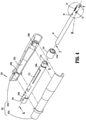
- an exemplary cartridge alignment mechanism for use with an endoscopic surgical device in the form of an endoscopic surgical tack applier 10 is shown generally as 100.
- the endoscopic surgical tack applier 10 includes a handle assembly 20 and an endoscopic tack retaining/advancing assembly 30 extending from the handle assembly 20 and configured to selectively release or fire a plurality of tacks or anchors 80 ( FIG. 8 ).
- An engagement portion 300 of the endoscopic tack retaining/advancing assembly 30 detachably supports a reloadable cartridge 50 ( FIG. 4 ) including the plurality of tacks 80.
- the cartridge alignment mechanism 100 includes a shipping clip 200 (see also, e.g., FIGS.
- the cartridge alignment mechanism 100 facilitates loading of the reloadable cartridge 50 onto the endoscopic tack retaining/advancing assembly 30. Specifically, the cartridge alignment mechanism 100 aligns the reloadable cartridge 50 to the engagement portion 300 without having to place the reloadable cartridge 50 in proper orientation (e.g., radial orientation) with the engagement portion 300, as will be discussed hereinbelow.
- the handle assembly 20 includes a button 22 configured to fire the plurality of tacks 80 ( FIG. 8 ) from the reloadable cartridge 50 ( FIG. 4 ) mounted on the engagement portion 300 of the endoscopic tack retaining/advancing assembly 30.
- the button 22 is operatively connected to a drive mechanism as known by one skilled in the art such that actuation of the button 22 results in rotation of a drive shaft 32 ( FIG. 3 ) of the tack retaining/advancing assembly 30 which, in turn, selectively fires the tacks 80 from the reloadable cartridge 50 through, e.g., a surgical mesh, and into tissue.
- the drive mechanism may include, e.g., a flexible shaft, to impart rotation to the reloadable cartridge 50.
- the drive mechanism may be coupled to an actuator 24 such as, e.g., an electric motor, in the handle assembly 20 such that actuation of the button 22 results in rotation of the drive shaft 32.
- the drive mechanism may be mechanically actuated.
- the handle assembly 20 further includes a slider 26 that is operatively coupled to the drive shaft 32 to impart axial displacement to the drive shaft 32.
- the slider 26 may be mechanically or electro-mechanically actuated as known by one skilled in the art.
- FIG. 2 illustrates the cartridge alignment mechanism 100 including the shipping clip 200 and the engagement portion 300 of the endoscopic tack retaining and advancing assembly 30.
- FIG. 3 illustrates the engagement portion 300 configured to operatively engage the reloadable cartridge 50 disposed within the shipping clip 200 ( FIG. 2 ).
- the engagement portion 300 is at a distal end portion 30a of the endoscopic tack retaining/advancing assembly 30.
- the endoscopic tack retaining/advancing assembly 30 defines a channel extending through the engagement portion 300.
- the channel is configured to receive the drive shaft 32 therein.
- the drive shaft 32 includes a mating tip 32a extending distally from the engagement portion 300.
- the mating tip 32a is configured to engage a tack holder 60 ( FIG.
- the engagement portion 300 includes a distal end portion 302 having a camming surface 304 configured to engage cartridge orientation guides 52 ( FIG. 4 ) of the reloadable cartridge 50, as will be discussed.
- the camming surface 304 may be tapered along a length of the engagement portion 300.
- the engagement portion 300 defines a recess 312.
- the engagement portion 300 further includes a finger 306 disposed in the recess 312.
- the finger 306 is radially flexible.
- the finger 306 includes a release member 306a configured to selectively engage a cartridge locking portion 53 ( FIG.
- the engagement portion 300 further defines orientation slots 308 (only one shown) dimensioned to slidably receive the respective cartridge orientation guides 52 ( FIG. 4 ) of the reloadable cartridge 50.
- the orientation slots 308 may diametrically oppose each other.
- the orientation slots 308 extend from a proximal-most portion 304b of the camming surface 304 such that when the cartridge orientation guides 52 rotatably engage the camming surface 304, the cartridge orientation guides 52 are directed into the respective orientation slots 308 of the engagement portion 300.
- the camming surface 304 may include a pair of diametrically opposing distal-most portions 304a and a pair of diametrically opposing proximal-most portions 304b (only one shown).
- Each orientation slot 308 extends axially to slidably receive the corresponding cartridge orientation guide 52.
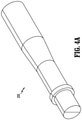
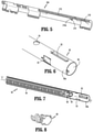
- FIGS. 4 and 5 illustrate the shipping clip 200 including an outer body portion 202 and an inner body portion 204.
- the outer body portion 202 includes first and second body halves 202a, 202b that define a cavity 202c rotatably supporting the inner body portion 204 therein.
- the outer body portion 202 includes proximal and distal ribs 206a, 206b extending radially inward.
- the inner body portion 204 includes proximal and distal circular grooves 208a, 208b configured to rotatably receive the respective proximal and distal ribs 206a, 206b of the outer body portion 202.
- the inner body portion 204 defines a lumen 210 therethrough.
- the lumen 210 is dimensioned to receive at least a portion of the reloadable cartridge 50.
- the inner body portion 204 further includes a finger 212 that is radially flexible.
- the finger 212 may be radially biased inwards.
- the finger 212 includes a protrusion 214 extending radially inwards into the lumen 210.
- the protrusion 214 is configured to be received in a bore 54 ( FIG. 6 ) of the reloadable cartridge 50 to secure the reloadable cartridge 50 with the inner body portion 204 for concomitant rotation therewith.
- the protrusion 214 includes a ramp 214a that enables the protrusion 214 to be disengaged from the bore 54 when the reloadable cartridge 50 is axially displaced from the shipping clip 200.
- the outer body portion 202 may include a non-uniform diameter. For example, a diameter of a proximal portion of the outer body portion 202 may be greater than a diameter of a distal portion of the outer body portion 202.
- the inner body portion 204 may further include a sleeve 216 ( FIG. 4 ) defining a passage 216a therethrough.
- the sleeve 216 may be coupled to a proximal portion of the inner body portion 204 to be received in a proximal portion of the cavity 202c of the outer body portion 202.
- the passage 216a of the sleeve 216 is dimensioned to receive the reloadable cartridge 50 therethrough. It is contemplated that the sleeve 216 may be integrally formed with the inner body portion 204.
- FIGS. 6-8 illustrate the reloadable cartridge 50 defining a lumen 56 therethrough.
- the lumen 56 is dimensioned to receive the tack holder 60 supporting serially arranged tacks 80.
- the tack holder 60 has a mouth 62 at a proximal portion of the tack holder 60 to receive the mating tip 32a ( FIG. 3 ) of the drive shaft 32.
- the mouth 62 has a cross-section complementary to the cross-section of the mating tip 32a such that rotation of the drive shaft 32 imparts concomitant rotation to the tack holder 60.
- the reloadable cartridge 50 further includes a coil 64 disposed about the tack holder 60 such that rotation of the tack holder 60 advances the tacks 80 out of the reloadable cartridge 50.
- a proximal portion 50a of the reloadable cartridge 50 includes the cartridge orientation guides 52 that diametrically oppose each other. Each cartridge orientation guide 52 extends axially along a length of the reloadable cartridge 50.
- the proximal portion 50a further includes the cartridge locking portion 53 that secures the reloadable cartridge 50 to the engagement portion 300 (see FIG. 20 ) of the endoscopic tack retaining/advancing assembly 30, as will be discussed hereinbelow.
- the cartridge locking portion 53 may define an acute angle with respect to a longitudinal axis "L-L" defined by the reloadable cartridge 50.
- the cartridge locking portions 53 may diametrically oppose each other and may define an axis orthogonal to an axis defined by the cartridge orientation guides 52.
- the proximal portion 50a further defines the bore 54 distal of the cartridge orientation guides 52.
- the bore 54 is dimensioned to receive the protrusion 214 ( FIG. 5 ) of the finger 212 of the inner body portion 204 to secure the reloadable cartridge 50 to the inner body portion 204 for concomitant rotation therewith.
- FIGS. 9 and 10 illustrate the reloadable cartridge 50 detachably supported within the inner body portion 204 of the shipping clip 200.
- the proximal and distal ribs 206a, 206b of the outer body portion 202 are received in the respective proximal and distal circular grooves 208a, 208b of the inner body portion 204 to enable rotation of the inner body portion 204 within the outer body portion 202 independent of the outer body portion 202.
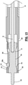
- FIGS. 11 and 12 illustrate the reloadable cartridge 50 coupled to the inner body portion 204 to enable concomitant rotation.
- the protrusion 214 that extends radially inward from the finger 212 of the inner body portion 204 is received in the bore 54 of the reloadable cartridge 50 to enable concomitant rotation.
- FIG. 13 illustrates the engagement portion 300 of the endoscopic tack retaining/advancing assembly 30.
- the engagement portion 300 includes the finger 306 disposed within the recess 312 defined in the engagement portion 300.
- the finger 306 has the release member 306a selectively securing the reloadable cartridge 50 ( FIG. 4 ) to the engagement portion 300.
- the finger 306 is biased radially inwards, but radially flexible to enable outward displacement of the release member 306 away from the drive shaft 32.
- the drive shaft 32 has a head portion 33 rotatably and slidably supported in the engagement portion 300.
- the head portion 33 includes a first portion 33a having a first diameter and a second portion 33b distal of the first portion 33a and having a second diameter greater than the first diameter.
- the head portion 33 may further include a transition portion 33c that extends between the first and second portions 33a, 33b.
- the release member 306a of the finger 306 is disposed on the first portion 33a of the head portion 33.
- the release member 306 rides along the third portion 33c towards the second portion 33b, thereby extending the release member 306a radially outwards.
- the outward displacement of the release member 306a may transition the cartridge locking portion 53 ( FIG. 6 ) of the reloadable cartridge 50 from a secured position ( FIG. 20 ) to a released position ( FIG. 24 ) in order to selectively secure the reloadable cartridge 50 to the engagement portion 300 of the endoscopic tack retaining/advancing assembly 30, as will be discussed hereinbelow.
- FIGS. 14 and 15 illustrate a method of loading the reloadable cartridge 50 onto the engagement portion 300 of the endoscopic tack retaining/advancing assembly 30.
- the reloadable cartridge 50 is secured with the inner body portion 204 and is rotatably supported within the outer body portion 202 of the shipping clip 200.
- FIGS. 16-19 illustrate coupling of the engagement portion 300 of the endoscopic tack retaining/advancing assembly 30 with the reloadable cartridge 50 by first inserting the mating tip 32a of the drive shaft 32 into the lumen 56 ( FIG. 6 ) of the reloadable cartridge 50.
- FIG. 20 illustrates the cartridge locking portion 53 of the reloadable cartridge 50 that is biased radially inwards.
- the cartridge locking portion 53 of the reloadable cartridge 50 is received into the recess 312 defined by the engagement portion 300 and engages a support wall 310 of the engagement portion 300. Under such a configuration, when the cartridge locking portion 53 engages the support wall 310, the reloadable cartridge 50 is secured with the engagement portion 300.
- FIGS. 21 and 22 illustrate a method of separating the shipping clip 200 from the reloadable cartridge 50 which is now attached to the engagement portion 300 of the endoscopic tack retaining/advancing assembly 30.
- the ramp 214a of the protrusion 214 slides out of the bore 54 of the reloadable cartridge 50, e.g., the finger 212 of the inner body portion 204 of the shipping clip 200 is pivoted in the direction of an arrow "K".
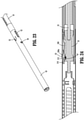
- the shipping clip 200 is detached from the reloadable cartridge 50 now coupled to the endoscopic tack retaining/advancing assembly 30 (see FIG. 23 ).
- the endoscopic surgical tack applier 10 may be used as needed by the clinician to apply the tacks 80 to a desired surgical site.
- the button 22 on the handle assembly 20 may be pressed by the clinician to eject tacks 80 from the reloadable cartridge 50.
- the reloadable cartridge 50 may be removed from the endoscopic tack retaining/advancing assembly 30 or replaced with a new reloadable cartridge 50.
- the clinician may operate the slider 26 of the handle assembly 20 to mechanically or electro-mechanically retract the drive shaft 32 in the direction of an arrow "R".
- the release member 306a of the finger 306 of the engagement portion 300 rides on the transition portion 33c and to the second portion 33b of the head portion 33 of the drive shaft 32. In this manner, the release member 306a urges the cartridge locking portion 53 of the reloadable cartridge 50 radially outwards of the support wall 310.
- the cartridge locking portion 53 of the reloadable cartridge 50 that is biased radially inwards is now positioned out of the recess 312 of the engagement portion 300 such that the reloadable cartridge 50 is detachable from the engagement portion 300.
- a new reloadable cartridge 30 may be loaded onto the engagement portion 300 of the endoscopic tack retaining/advancing assembly 30 through the steps discussed hereinabove.
- the cartridge alignment mechanism 100 described hereinabove facilitates loading and unloading of the reloadable cartridge 50 on the engagement portion 300 of the endoscopic tack retaining/advancing assembly 300.
- the loading of the reloadable cartridge 50 may be affected without aligning the orientation of the reload cartridge 50 and the engagement portion 300. Rather, the cartridge alignment mechanism 100 self-aligns the two components irrespective of the initial relative orientation of the two components. It is also envisioned that the cartridge alignment mechanism 100 may be configured for use in a robotic surgical system.
Landscapes
- Health & Medical Sciences (AREA)
- Life Sciences & Earth Sciences (AREA)
- Surgery (AREA)
- Heart & Thoracic Surgery (AREA)
- Engineering & Computer Science (AREA)
- Biomedical Technology (AREA)
- Nuclear Medicine, Radiotherapy & Molecular Imaging (AREA)
- Medical Informatics (AREA)
- Molecular Biology (AREA)
- Animal Behavior & Ethology (AREA)
- General Health & Medical Sciences (AREA)
- Public Health (AREA)
- Veterinary Medicine (AREA)
- Surgical Instruments (AREA)
Applications Claiming Priority (2)
| Application Number | Priority Date | Filing Date | Title |
|---|---|---|---|
| US202063054438P | 2020-07-21 | 2020-07-21 | |
| US17/329,694 US20220022866A1 (en) | 2020-07-21 | 2021-05-25 | Cartridge alignment mechanism for use with surgical devices |
Publications (1)
| Publication Number | Publication Date |
|---|---|
| EP3943016A1 true EP3943016A1 (fr) | 2022-01-26 |
Family
ID=76999673
Family Applications (1)
| Application Number | Title | Priority Date | Filing Date |
|---|---|---|---|
| EP21186599.3A Withdrawn EP3943016A1 (fr) | 2020-07-21 | 2021-07-20 | Mécanisme d'alignement de cartouche pour une utilisation avec des dispositifs chirurgicaux |
Country Status (6)
| Country | Link |
|---|---|
| US (1) | US20220022866A1 (fr) |
| EP (1) | EP3943016A1 (fr) |
| JP (1) | JP2022021308A (fr) |
| CN (1) | CN113951944A (fr) |
| AU (1) | AU2021203936A1 (fr) |
| CA (1) | CA3123740A1 (fr) |
Families Citing this family (1)
| Publication number | Priority date | Publication date | Assignee | Title |
|---|---|---|---|---|
| USD1109327S1 (en) * | 2024-09-06 | 2026-01-13 | Covidien Lp | Handle for a surgical instrument |
Citations (3)
| Publication number | Priority date | Publication date | Assignee | Title |
|---|---|---|---|---|
| EP3069663A1 (fr) * | 2015-03-17 | 2016-09-21 | Covidien LP | Effecteurs d'extrémité de connexion à dispositifs chirurgicaux |
| EP3207881A1 (fr) * | 2016-02-22 | 2017-08-23 | Covidien LP | Instrument chirurgical comprenant un effecteur d'extrémité rotatif et une structure de limitation de rotation |
| EP3572009A2 (fr) * | 2018-05-02 | 2019-11-27 | Covidien LP | Cale de transport pour l'installation d'un effecteur d'extrémité sur des dispositifs chirurgicaux |
Family Cites Families (10)
| Publication number | Priority date | Publication date | Assignee | Title |
|---|---|---|---|---|
| JP4297603B2 (ja) * | 2000-09-19 | 2009-07-15 | 株式会社トップ | 外科用ステープラ |
| JP4545589B2 (ja) * | 2002-10-04 | 2010-09-15 | タイコ ヘルスケア グループ エルピー | 外科的ステープルデバイスのためのツールアセンブリ |
| DE102009018821A1 (de) * | 2009-04-24 | 2010-10-28 | Aesculap Ag | Chirurgisches Instrument zum Anlegen von Ligaturklammern |
| US8931679B2 (en) * | 2011-10-17 | 2015-01-13 | Covidien Lp | Surgical stapling apparatus |
| CN202950700U (zh) * | 2012-11-07 | 2013-05-29 | 北京中法派尔特医疗设备有限公司 | 一种钉仓组件以及应用该钉仓组件的吻合器 |
| JP6636452B2 (ja) * | 2014-04-16 | 2020-01-29 | エシコン エルエルシーEthicon LLC | 異なる構成を有する延在部を含む締結具カートリッジ |
| US10159483B2 (en) * | 2015-02-27 | 2018-12-25 | Ethicon Llc | Surgical apparatus configured to track an end-of-life parameter |
| US20180168608A1 (en) * | 2016-12-21 | 2018-06-21 | Ethicon Endo-Surgery, Llc | Surgical instrument system comprising an end effector lockout and a firing assembly lockout |
| US11083470B2 (en) * | 2018-03-06 | 2021-08-10 | Viant As&O Holdings Llc | Expandable reamer cutting head |
| US11207067B2 (en) * | 2018-03-28 | 2021-12-28 | Cilag Gmbh International | Surgical stapling device with separate rotary driven closure and firing systems and firing member that engages both jaws while firing |
-
2021
- 2021-05-25 US US17/329,694 patent/US20220022866A1/en not_active Abandoned
- 2021-06-15 AU AU2021203936A patent/AU2021203936A1/en not_active Abandoned
- 2021-06-30 CA CA3123740A patent/CA3123740A1/fr active Pending
- 2021-07-01 JP JP2021109891A patent/JP2022021308A/ja active Pending
- 2021-07-06 CN CN202110761006.0A patent/CN113951944A/zh active Pending
- 2021-07-20 EP EP21186599.3A patent/EP3943016A1/fr not_active Withdrawn
Patent Citations (3)
| Publication number | Priority date | Publication date | Assignee | Title |
|---|---|---|---|---|
| EP3069663A1 (fr) * | 2015-03-17 | 2016-09-21 | Covidien LP | Effecteurs d'extrémité de connexion à dispositifs chirurgicaux |
| EP3207881A1 (fr) * | 2016-02-22 | 2017-08-23 | Covidien LP | Instrument chirurgical comprenant un effecteur d'extrémité rotatif et une structure de limitation de rotation |
| EP3572009A2 (fr) * | 2018-05-02 | 2019-11-27 | Covidien LP | Cale de transport pour l'installation d'un effecteur d'extrémité sur des dispositifs chirurgicaux |
Also Published As
| Publication number | Publication date |
|---|---|
| AU2021203936A1 (en) | 2022-02-10 |
| JP2022021308A (ja) | 2022-02-02 |
| CA3123740A1 (fr) | 2022-01-21 |
| CN113951944A (zh) | 2022-01-21 |
| US20220022866A1 (en) | 2022-01-27 |
Similar Documents
| Publication | Publication Date | Title |
|---|---|---|
| EP3351189B1 (fr) | Instrument de traitement endoscopique | |
| US10010326B2 (en) | Endoscopic treatment tool | |
| US9308011B2 (en) | Surgical device and methods | |
| US10595873B2 (en) | Surgical staplers and related methods | |
| JP5554339B2 (ja) | 複数の縫合糸アンカーを適用する方法及び装置 | |
| CN104837415B (zh) | 具有扩张特征结构的经口圆形砧座引入系统 | |
| US7648514B1 (en) | Deep endoscopic staple and stapler | |
| JP5513276B2 (ja) | ダブルカートリッジとアンビルアセンブリとを有する外科手術器具 | |
| US10045763B2 (en) | Endoscopic treatment tool set | |
| EP3158950A1 (fr) | Enclume inclinable à fente t pour instrument d'agrafage circulaire | |
| EP2253278A1 (fr) | Agrafeuse chirurgicale avec mécanisme de verrouillage | |
| WO2008089404A2 (fr) | Introducteur d'enclume avec agrafeuse circulaire | |
| EP3607867B1 (fr) | Dispositif de recharge d'aiguille à utiliser avec un dispositif endostitch | |
| JP2000166932A (ja) | 自動吻合器及び該吻合器に装着可能な案内バルーン | |
| CN113766885A (zh) | 用于紧固组织的系统、装置及相关方法 | |
| EP3777650A1 (fr) | Système de chirurgie endoluminale | |
| EP3311755B1 (fr) | Effecteurs d'extrémité chirurgicaux | |
| CN115279281A (zh) | 用于紧固组织的系统、设备和相关方法 | |
| US20220022866A1 (en) | Cartridge alignment mechanism for use with surgical devices | |
| US20130238000A1 (en) | Wound closure device | |
| WO2015065484A1 (fr) | Appareil d'application d'agrafes chirurgicales | |
| WO2015139197A1 (fr) | Appareil d'application d'agrafes chirurgicales | |
| US20080275501A1 (en) | Medical device loading and delivery systems and methods | |
| CN117295457A (zh) | 用于在低位前切除手术过程中缩短直肠残端的装置及方法 | |
| WO2025217302A1 (fr) | Systèmes et procédés de distribution de dispositifs associés à une anastomose magnétique à l'aide de robots chirurgicaux |
Legal Events
| Date | Code | Title | Description |
|---|---|---|---|
| PUAI | Public reference made under article 153(3) epc to a published international application that has entered the european phase |
Free format text: ORIGINAL CODE: 0009012 |
|
| STAA | Information on the status of an ep patent application or granted ep patent |
Free format text: STATUS: THE APPLICATION HAS BEEN PUBLISHED |
|
| AK | Designated contracting states |
Kind code of ref document: A1 Designated state(s): AL AT BE BG CH CY CZ DE DK EE ES FI FR GB GR HR HU IE IS IT LI LT LU LV MC MK MT NL NO PL PT RO RS SE SI SK SM TR |
|
| STAA | Information on the status of an ep patent application or granted ep patent |
Free format text: STATUS: REQUEST FOR EXAMINATION WAS MADE |
|
| 17P | Request for examination filed |
Effective date: 20220718 |
|
| RBV | Designated contracting states (corrected) |
Designated state(s): AL AT BE BG CH CY CZ DE DK EE ES FI FR GB GR HR HU IE IS IT LI LT LU LV MC MK MT NL NO PL PT RO RS SE SI SK SM TR |
|
| STAA | Information on the status of an ep patent application or granted ep patent |
Free format text: STATUS: THE APPLICATION HAS BEEN WITHDRAWN |
|
| 18W | Application withdrawn |
Effective date: 20240711 |