EP3943260B1 - Vorrichtung und verfahren zum herstellen einer verschlusskappe - Google Patents
Vorrichtung und verfahren zum herstellen einer verschlusskappe Download PDFInfo
- Publication number
- EP3943260B1 EP3943260B1 EP21020251.1A EP21020251A EP3943260B1 EP 3943260 B1 EP3943260 B1 EP 3943260B1 EP 21020251 A EP21020251 A EP 21020251A EP 3943260 B1 EP3943260 B1 EP 3943260B1
- Authority
- EP
- European Patent Office
- Prior art keywords
- closure cap
- connecting flange
- retaining ring
- carrier
- slot
- Prior art date
- Legal status (The legal status is an assumption and is not a legal conclusion. Google has not performed a legal analysis and makes no representation as to the accuracy of the status listed.)
- Active
Links
Images


Classifications
-
- B—PERFORMING OPERATIONS; TRANSPORTING
- B26—HAND CUTTING TOOLS; CUTTING; SEVERING
- B26D—CUTTING; DETAILS COMMON TO MACHINES FOR PERFORATING, PUNCHING, CUTTING-OUT, STAMPING-OUT OR SEVERING
- B26D1/00—Cutting through work characterised by the nature or movement of the cutting member or particular materials not otherwise provided for; Apparatus or machines therefor; Cutting members therefor
- B26D1/01—Cutting through work characterised by the nature or movement of the cutting member or particular materials not otherwise provided for; Apparatus or machines therefor; Cutting members therefor involving a cutting member which does not travel with the work
- B26D1/02—Cutting through work characterised by the nature or movement of the cutting member or particular materials not otherwise provided for; Apparatus or machines therefor; Cutting members therefor involving a cutting member which does not travel with the work having a stationary cutting member
- B26D1/03—Cutting through work characterised by the nature or movement of the cutting member or particular materials not otherwise provided for; Apparatus or machines therefor; Cutting members therefor involving a cutting member which does not travel with the work having a stationary cutting member with a plurality of cutting members
- B26D1/035—Cutting through work characterised by the nature or movement of the cutting member or particular materials not otherwise provided for; Apparatus or machines therefor; Cutting members therefor involving a cutting member which does not travel with the work having a stationary cutting member with a plurality of cutting members for thin material, e.g. for sheets, strips or the like
-
- B—PERFORMING OPERATIONS; TRANSPORTING
- B26—HAND CUTTING TOOLS; CUTTING; SEVERING
- B26D—CUTTING; DETAILS COMMON TO MACHINES FOR PERFORATING, PUNCHING, CUTTING-OUT, STAMPING-OUT OR SEVERING
- B26D7/00—Details of apparatus for cutting, cutting-out, stamping-out, punching, perforating, or severing by means other than cutting
- B26D7/01—Means for holding or positioning work
-
- B—PERFORMING OPERATIONS; TRANSPORTING
- B26—HAND CUTTING TOOLS; CUTTING; SEVERING
- B26D—CUTTING; DETAILS COMMON TO MACHINES FOR PERFORATING, PUNCHING, CUTTING-OUT, STAMPING-OUT OR SEVERING
- B26D7/00—Details of apparatus for cutting, cutting-out, stamping-out, punching, perforating, or severing by means other than cutting
- B26D7/06—Arrangements for feeding or delivering work of other than sheet, web, or filamentary form
-
- B—PERFORMING OPERATIONS; TRANSPORTING
- B26—HAND CUTTING TOOLS; CUTTING; SEVERING
- B26D—CUTTING; DETAILS COMMON TO MACHINES FOR PERFORATING, PUNCHING, CUTTING-OUT, STAMPING-OUT OR SEVERING
- B26D7/00—Details of apparatus for cutting, cutting-out, stamping-out, punching, perforating, or severing by means other than cutting
- B26D7/08—Means for treating work or cutting member to facilitate cutting
- B26D7/10—Means for treating work or cutting member to facilitate cutting by heating
-
- B—PERFORMING OPERATIONS; TRANSPORTING
- B26—HAND CUTTING TOOLS; CUTTING; SEVERING
- B26D—CUTTING; DETAILS COMMON TO MACHINES FOR PERFORATING, PUNCHING, CUTTING-OUT, STAMPING-OUT OR SEVERING
- B26D1/00—Cutting through work characterised by the nature or movement of the cutting member or particular materials not otherwise provided for; Apparatus or machines therefor; Cutting members therefor
- B26D1/0006—Cutting members therefor
- B26D2001/006—Cutting members therefor the cutting blade having a special shape, e.g. a special outline, serrations
-
- B—PERFORMING OPERATIONS; TRANSPORTING
- B26—HAND CUTTING TOOLS; CUTTING; SEVERING
- B26F—PERFORATING; PUNCHING; CUTTING-OUT; STAMPING-OUT; SEVERING BY MEANS OTHER THAN CUTTING
- B26F2210/00—Perforating, punching, cutting-out, stamping-out, severing by means other than cutting of specific products
- B26F2210/04—Making plastic pilferproof screw caps by cutting a tamper ring
Definitions
- the invention relates to a device for producing a closure cap on a connecting flange, for example a screw cap on the neck of a plastic bottle.
- the screw cap of a plastic bottle which is typically designed as a plastic cap, should still be connected to the bottle after it has been opened, in order to prevent the screw cap from getting into the environment.
- the screw cap forms a closure cap consisting of a retaining ring and a plastic lid formed in one piece with the retaining ring, one or more slots being introduced between the retaining ring and the lid, which allow a relative movement of the lid relative to the retaining ring when screwed on.
- the retaining ring sits on a connecting flange which is located on the bottle neck of the plastic bottle and is connected to it.
- the introduction of one or more slits between the retaining ring and the cover is automated in Devices in which the cap, retaining ring and lid are received and provided with the desired slits or tear lines in an automated process.
- a device is for example in EP 1 021 282 B1 , which forms the basis for the preamble of claim 1, or EP 0 619 168 A1 described.
- the one in the EP 1 021 282 B1 The device described has an axially displaceable dome which accommodates a closure cap. Clamping jaws are pivotably mounted on the device, on which circular blades are accommodated. To create a tear line in the wall of the cap, the jaws with the blades are engaged with the wall of the cap.
- the one in the EP 0 619 168 A1 The device described comprises a plurality of domes for receiving a closure cap on a rotating carousel, the domes also being mounted such that they can rotate about their own axis. To make a slit in the wall of the closure cap, a radially offset knife engages with the closure cap.
- the object of the invention is to simplify the manufacture of closure caps which are seated on a connecting flange and are formed with a retaining ring and a lid.
- closure caps which are seated on a connecting flange with an opening and have a retaining ring and a cover which is formed in one piece with the retaining ring and is connected to the retaining ring.
- closure caps are placed, for example, as a screw cap on plastic bottles or on plasticized cardboard containers and are opened by turning the lid, which is designed as a screw cap, with the relative movement of the lid being made possible due to slots between the lid and the retaining ring.
- closure caps which are designed with a retaining ring and a cover can also be considered, with the cover not being able to be opened by turning but by tilting or snapping open about a transverse axis.
- the open lid remains connected to the retaining ring.
- the transverse axis lies in a hinge that goes through one or more slits formed between the retaining ring and the lid.
- sealing cap and connecting flange can be connected to a bottle or a beverage container.
- the connecting flange forms a connecting and carrier part which, on the one hand, is the carrier of the closure cap and, on the other hand, connects the closure cap to the bottle or beverage container.
- the device according to the invention enables the closure cap to be assembled with the connecting flange in an assembly section, in that the closure cap, consisting of a retaining ring and a cover formed in one piece with the retaining ring, is placed on the connecting flange before slots are made for the retaining ring and cover in the assembly section and thereby is connected to this.
- the same device also enables the slit or plural slits to be made between the retaining ring and the cover in a slit section of the device.
- the slit section for making the slit and the assembly section are both located in the same device, with the assembly section first being passed through in order to produce the closure cap on the connecting flange, followed by the slit section.
- This device combines both the assembly and the making of one or more slots. It eliminates the need to provide various devices for the assembly and the introduction of the slots between which the Caps including the connecting flange have to be transported back and forth.
- the device according to the invention only has to be supplied once with the connecting flange and the closure cap, which are then first mounted and then slotted.
- closure cap Since the closure cap is initially placed on the connecting flange in the non-slotted state, the closure cap has increased stability, which reduces the risk that the forces occurring when the closure cap is placed on the connection flange will damage or destroy the closure cap.
- the closure cap can, for example, be pressed onto the connecting flange by the force of a press die, with the pressing forces being absorbed non-destructively due to the one-piece design of the retaining ring and cover.
- the device has a feed section for feeding the closure cap and connecting flange and a delivery section for dispensing the mounted closure cap on the connection flange, including slots between the retaining ring and the lid of the closure cap.
- the feed section comprises at least two feed tracks, via which the connecting flanges and the closure caps can each be fed to a central area of the device, in which the assembly and the slitting take place. If necessary, there can also be more than two feed tracks in the feed section, for example three feed tracks, in order to feed in a further component which is connected to the closure cap and connecting flange. at This further component is, for example, a cutting ring which, during assembly, can be inserted into an opening in the connecting flange on the side opposite the closure cap. The cutting ring makes it possible to cut an opening, for example in the wall of a beverage container, for inserting the combination of connecting flange and closure cap.
- the central area has a plurality of carrier stamps, each carrier stamp receiving a connecting flange and a closure cap.
- the carrier stamps belong to the assembly section of the device. According to a further advantageous embodiment, the carrier stamps are designed to be adjustable in height.
- the central area also includes a slitting section with a slitting blade radially spaced from the carrier punches.
- the carrier stamps are arranged on a rotary ring or a carousel of the central area, which is mounted so that it can rotate about an axis.
- the carousel and the rotating ring are also part of the assembly section.
- This embodiment enables the device to be operated with a plurality of carrier stamps arranged on the rotary ring or carousel, the longitudinal axis of which is arranged parallel to the axis of rotation of the rotary ring.
- Each carrier stamp accommodates a connecting flange and a closure cap, the fixed connection between the connecting flange and the closure cap being effected via a press stamp, which is also arranged in the central area and can be lowered onto a carrier stamp in order to seal the cap with the to connect the connecting flange.
- each carrier stamp can be assigned its own press stamp.
- the rams can also be arranged on the rotating ring of the central area and, together with the rotating ring or carousel, can perform a rotational movement about the axis of rotation. The rams are part of the assembly section.
- the slitting section comprises at least one slitting knife, where appropriate several slitting knives, for example two or three slitting knives, can be provided, which are advantageously arranged one above the other, which makes it possible to create several superimposed slits between the retaining ring and the cover.
- the carrier stamps are designed to be rotatable about their longitudinal axis.
- the carrier stamps can not only perform a rotational movement with the rotary ring or carousel of the central area, but also a rotational movement about their own longitudinal axis, which enables a slot that extends over a large circumferential section, especially while driving past the slot section a circumferential section of at least 180° up to, for example, 330°.
- the speed of rotation of the rotating ring or carousel and the speed of rotation of carrier stamps around their Longitudinal axis are adjustable.
- the rotational speeds can be coupled in such a way that as the carrier punches travel along the slot knife, the slot is produced over the desired angular segment along the circumference.
- the ram or rams that are arranged in the central area are designed to be lowerable.
- the press ram which is located above the carrier ram, is lowered in order to exert a desired contact pressure on the closure cap, whereby the closure cap reaches its desired position on the connecting flange.
- the retaining ring advantageously assumes a position on the connecting flange in which the retaining ring is in a latching position, so that the retaining ring remains in its desired position on the connecting flange with the usual forces required to open the lid, even if the lid is open.
- the slitting blade in the slitting section is designed in the shape of a part circle.
- the carrier stamps and the closure caps arranged thereon also correspondingly perform a rotary movement, regardless of the movement of their own about the longitudinal axis of the carrier stamps. This turning movement is taken into account by the pitch circle shape of the slitting knife.
- the slitting knife can be heatable in order to facilitate the making of the desired slit in the plastic material for the closure cap.
- the heated slitting knife causes due to its increased Temperature melts the plastic material of the cap, which facilitates the cutting process.
- the invention also relates to a method for producing slotted closure caps on a connecting flange, the method being carried out on a device as described above.
- production takes place in two steps, with the closure cap being applied to the connecting flange in the unslit state in the first step and the slit between the retaining ring and the lid of the closure cap being introduced in the second, subsequent step.
- the closure cap can be adjusted between a closed and an open state; it is designed, for example, as a screw cap, so that an opening in the connecting flange is opened and closed by a screwing movement.
- a screw cap there is a thread on a neck in the connecting flange, in particular an external thread, with a cover of the closure cap being provided with a corresponding internal thread which can be screwed onto the external thread on the connecting flange.
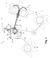
- the device 1 comprises a central area 2 in which the assembly of the cap and the connecting flange is carried out and also the making of one or more slits between a retaining ring and the lid of the cap.
- the retaining ring and cover of the closure cap are designed as a one-piece component that is fed to the central area 2 of the device 1 without a slit.
- the device 1 also includes feed sections 3, 4, 5, via which the various individual parts that are to be assembled are fed to the central region 2.
- the connecting flanges are fed in in the feed section 3
- the cutting rings are fed in in the feed section 4
- the closure caps are fed in in the feed section 5 .
- the feed sections 3 , 4 , 5 are connected to the central area 2 via feed tracks 6 , 7 , 8 .
- the cutting rings which are fed to the central region 2 via the feed section 4 and the feed track 7, are inserted into the central opening in the connecting flange, with a toothing of the cutting ring protruding from the opening in the connecting flange on the side opposite the closure cap.
- the structural unit comprising the closure cap, the connecting flange and the cutting ring, can be cut into the wall of a beverage container made of plastic or cardboard via the cutting ring.
- the central area 2 of the device 1 includes a carousel 9, in which the assembly takes place and also the slots between the retaining ring and the cover of the closure caps are made.
- the slots are created in one Slot section 10, which is located radially at a small distance from the carousel 9.
- the carousel 9 can rotate as a whole, or the central area 2 comprises a rotating ring, the axis of rotation of the carousel or rotating ring being designed as a vertical axis and in the representation according to FIG 1 perpendicular to the image plane.
- the mounted caps on the connecting flange including the cutting ring pass the slit section 10 and are scored by one or more slitting knives, so that one or more slits are created between the retaining ring and the lid of the cap.
- the central area 2 also includes a control panel 11 and an output section 12, via which the completely assembled and slotted structural units with sealing cap, connecting flange and cutting ring are output.
- the various actuators in the device are advantageously driven hydraulically, pneumatically or electrically.
- the rotary movement of the rotary ring or a carousel with the rotary ring can be carried out with the aid of an electric motor, as can the rotary movement of the carrier stamps about their longitudinal axis.
- the height adjustability of the support stamp and/or press stamp is preferably hydraulic or pneumatic.
- the carousel 9 has a plurality of parallel turntables, of which the lower turntable is identified by reference number 13, the carousel 9 rotating about a central axis of rotation 14 ( 6 ), the at the same time represents a vertical axis, is rotatably mounted.
- the carousel 9 has a number of carrier stamps 15 distributed over its circumference on the outer circumference, which are each arranged to be height-adjustable and along their longitudinal axis—parallel to the axis of rotation 14 of the carousel 9—are height-adjustable.
- the height can be adjusted via drive units 16 in the floor area of the carousel 9, with the drive units 16 preferably being designed hydraulically, optionally pneumatically.
- the carrier stamps 15 each accommodate a closure cap 17, a connecting flange 18 and a cutting ring, which form a coherent structural unit when assembled.
- the connecting flange 18 has a collar, which can be provided with an external thread, onto which a cover 17a of the closure cap 17, which is provided with an internal thread, is screwed.
- a retaining ring 17b is formed integrally with the cover 17a and sits on the collar or collar below the external thread on the connecting flange 18 and advantageously sits on the connecting flange 18 in a latching position.
- the cutting ring For assembly, first the cutting ring, then the connecting flange 18 and finally the closure cap 17 are placed on the support stamp 15 .
- the connection is made by actuating the drive unit 16 and pushing the carrier stamp 15 upwards, as a result of which the components lying loosely one on top of the other in the upper region of the carrier stamp 15 are pressed against a press stamp 19 fixedly arranged on the carousel.
- the closure cap 17 and the connecting flange 18 as well as the cutting ring are pressed onto one another axially.
- the height of the carrier stamp 15 is actively adjustable via the drive unit 16 , whereas the press stamp 19 is held stationary on the carousel 9 .
- a reversed embodiment is also possible with height-adjustable press dies 19 and carrier dies 15 held at a fixed height on the carousel 9.
- the assembly process takes place with a one-piece closure cap 17 with cover 17a and retaining ring 17b before the introduction of slots between the cover and retaining ring.
- a solid bond between the closure cap 17 and the connecting flange 18 including the cutting ring has been created, one or more slits are introduced between the cover 17a and the retaining ring 17b in a further step.
- the carousel 9 is rotated further about its axis of rotation 14 until the carrier stamp 15 with the closure cap 17 and connecting flange 18 and cutting ring arranged thereon reaches the area of the slot section 10 .
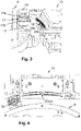
- the slitting section 10 is located radially outside of the carousel 9 and has two slitting knives 20a, 20b, one above the other in the vertical direction, which are curved or part-circular ( 3 , 5 ).
- the slitting knives 20a, 20b engage a portion of the cap 17 between the lid 17a and the retaining ring 17b, thereby making the desired slits in the cap 17.
- the slits extend in the circumferential direction of the closure cap 17.
- the carrier stamp 15 can perform a rotary movement about its longitudinal axis, which is parallel to the axis of rotation 14 of the carousel 9 runs. At this adjustable rotational movement, the slitting blades 20a, 20b come into contact over a desired large angular range with the peripheral side of the closure cap 17 in the section between the cover 17a and the retaining ring 17b.
- the start and end of the slit can be set via the angular velocity of the carrier stamp 15.
- the beginning and end of the slitting are also determined by the length of the slitting knives and any positioning that is offset in the circumferential direction, as well as a shorter or longer version of the slitting knives.
- the unit consisting of the closure cap 17, the connecting flange 18 and the cutting ring, can be dispensed via the dispensing section of the device.
Landscapes
- Life Sciences & Earth Sciences (AREA)
- Forests & Forestry (AREA)
- Engineering & Computer Science (AREA)
- Mechanical Engineering (AREA)
- Physics & Mathematics (AREA)
- Optics & Photonics (AREA)
- Closures For Containers (AREA)
- Making Paper Articles (AREA)
- Manufacturing Of Electrical Connectors (AREA)
Description
- Die Erfindung bezieht sich auf eine Vorrichtung zum Herstellen einer Verschlusskappe auf einem Verbindungsflansch, beispielsweise einem Schraubverschluss am Flaschenhals einer Kunststoffflasche.
- Aus Umweltschutzgründen soll der typischerweise als Kunststoffdeckel ausgebildete Schraubverschluss einer Kunststoffflasche nach dem Öffnen noch mit der Flasche verbunden sein, um zu verhindern, dass der Schraubverschluss in die Umwelt gelangt. Der Schraubverschluss bildet eine Verschlusskappe, bestehend aus einem Rückhaltering und einem einteilig mit dem Rückhaltering ausgebildeten Deckel aus Kunststoff, wobei zwischen Rückhaltering und Deckel ein oder mehrere Schlitze eingebracht sind, welche eine Relativbewegung des Deckels beim Aufschrauben gegenüber dem Rückhaltering ermöglichen. Der Rückhaltering sitzt auf einem Verbindungsflansch auf, der sich auf dem Flaschenhals der Kunststoffflasche befindet und mit diesem verbunden ist.
- Das Einbringen ein oder mehrerer Schlitze zwischen Rückhaltering und Deckel erfolgt automatisiert in Vorrichtungen, in denen die Verschlusskappe mit Rückhaltering und Deckel aufgenommen und in einem automatisierten Prozess mit den gewünschten Schlitzen oder Risslinien versehen wird. Eine derartige Vorrichtung wird beispielsweise in der
EP 1 021 282 B1 , die die Basis für den Oberbegriff des Anspruchs 1 bildet, oderEP 0 619 168 A1 beschrieben. Im Anschluss an das Einbringen des Schlitzes oder der Schlitze zwischen Rückhaltering und Deckel wird die Verschlusskappe in einer weiteren Vorrichtung zur Montage auf den Verbindungsflansch aufgesetzt. - Die in der
EP 1 021 282 B1 beschriebene Vorrichtung weist einen axial verschiebbaren Dom auf, der eine Verschlusskappe aufnimmt. An der Vorrichtung sind Klemmbacken verschwenkbar gelagert, an denen kreisförmige Klingen aufgenommen sind. Zur Erzeugung einer Risslinie in der Wand der Verschlusskappe werden die Klemmbacken mit den Klingen in Eingriff mit der Wand der Verschlusskappe gebracht. - Die in der
EP 0 619 168 A1 beschriebene Vorrichtung umfasst mehrere Dome zur Aufnahme einer Verschlusskappe auf einem rotierenden Karussell, wobei zusätzlich die Dome um ihre eigene Achse verdrehbar gelagert sind. Zum Einbringen eines Schlitzes in die Wand der Verschlusskappe gelangt ein radial versetzt angeordnetes Messer in Eingriff mit der Verschlusskappe. - Der Erfindung liegt die Aufgabe zugrunde, die Herstellung von Verschlusskappen, die auf einem Verbindungsflansch aufsitzen und mit einem Rückhaltering und einem Deckel ausgebildet sind, zu vereinfachen.
- Diese Aufgabe wird erfindungsgemäß mit den Merkmalen des Anspruches 1 gelöst. Die Unteransprüche geben zweckmäßige Weiterbildungen an.
- Die erfindungsgemäße Vorrichtung vereinfacht die Herstellung von Verschlusskappen, die auf einem Verbindungsflansch mit Öffnung aufsitzen und einen Rückhaltering sowie ein einteilig mit dem Rückhaltering ausgebildeten und mit dem Rückhaltering verbundenen Deckel aufweisen, in signifikanter Weise. Derartige Verschlusskappen werden beispielsweise als Schraubverschluss auf Kunststoffflaschen oder auf plastifizierte Kartonagenbehälter aufgesetzt und werden durch Drehen des Deckels geöffnet, der als ein Schraubverschluss ausgebildet ist, wobei aufgrund von Schlitzen zwischen Deckel und Rückhaltering die Relativbewegung des Deckels ermöglicht wird. Zugleich ist sichergestellt, dass trotz der Schlitze zwischen Deckel und Rückhaltering ein dauerhafter Verbund von Deckel und Rückhaltering bestehen bleibt, so dass der Deckel auch im geöffneten Zustand mit dem Rückhaltering verbunden ist, der sicher auf dem Verbindungsflansch aufsitzt. Auf diese Weise wird ein versehentliches Entsorgen des Deckels in die Umwelt vermieden. Der Deckel kann nach dem Öffnen auch wieder geschlossen werden.
- Alternativ zu einer als Schraubverschluss ausgebildeten Verschlusskappe kommen auch Verschlusskappen in Betracht, die mit einem Rückhaltering und einem Deckel ausgebildet sind, wobei der Deckel nicht durch Drehen, sondern durch Kippen oder Aufschnappen um eine Querachse zu öffnen ist. Auch in diesem fall bleibt der geöffnete Deckel mit dem Rückhaltering verbunden. Die Querachse liegt in einem Scharnier, das durch einen oder mehrere Schlitze zwischen Rückhaltering und Deckel gebildet ist.
- Die Kombination von Verschlusskappe und Verbindungsflansch kann mit einer Flasche oder einem Getränkebehälter verbunden werden. Der Verbindungsflansch bildet als Schnittstelle ein Verbindungs- und Trägerteil, das einerseits Träger der Verschlusskappe ist und andererseits die Verbindung der Verschlusskappe mit der Flasche oder dem Getränkebehälter herstellt.
- Die erfindungsgemäße Vorrichtung ermöglicht zum einen die Montage der Verschlusskappe mit dem Verbindungsflansch in einem Montageabschnitt, indem die Verschlusskappe, bestehend aus Rückhaltering und einteilig mit dem Rückhaltering ausgebildeten Deckel, noch vor dem Einbringen von Schlitzen zum Rückhaltering und Deckel im Montageabschnitt auf den Verbindungsflansch aufgesetzt und hierdurch mit diesem verbunden wird. Die gleiche Vorrichtung ermöglicht darüber hinaus in einem sich daran anschließenden Schritt das Einbringen des Schlitzes oder mehrerer Schlitze zwischen Rückhaltering und Deckel in einem Schlitzabschnitt der Vorrichtung. Der Schlitzabschnitt zum Einbringen des Schlitzes und der Montageabschnitt befinden sich beide in der gleichen Vorrichtung, wobei zum Herstellen der Verschlusskappe auf dem Verbindungsflansch zunächst der Montageabschnitt und anschließend der Schlitzabschnitt durchlaufen wird.
- Diese Vorrichtung vereint sowohl die Montage als auch das Einbringen eines oder mehrere Schlitze. Es entfällt die Notwendigkeit, verschiedene Vorrichtungen für die Montage und das Einbringen der Schlitze vorzuhalten, zwischen denen die Verschlusskappen einschließlich Verbindungsflansch hin und her transportiert werden müssen. Der erfindungsgemäßen Vorrichtung müssen lediglich einmalig der Verbindungsflansch und die Verschlusskappe zugeführt werden, die anschließend zuerst montiert und danach geschlitzt werden.
- Ein weiterer Vorteil der erfindungsgemäßen Vorrichtung liegt in der Reihenfolge von Montieren und Schneiden. Da zunächst die Verschlusskappe im nicht-geschlitzten Zustand auf den Verbindungsflansch aufgesetzt wird, weist die Verschlusskappe eine erhöhte Stabilität auf, wodurch das Risiko reduziert ist, dass die beim Aufsetzen der Verschlusskappe auf den Verbindungsflansch auftretenden Kräfte zu einer Beeinträchtigung oder Zerstörung der Verschlusskappe führen. Die Verschlusskappe kann beispielsweise durch die Kraft eines Pressstempels auf den Verbindungsflansch aufgedrückt werden, wobei aufgrund der Einteiligkeit von Rückhaltering und Deckel die Presskräfte zerstörungsfrei aufgenommen werden.
- Die Vorrichtung weist vorteilhafterweise einen Zuführabschnitt für die Zufuhr von Verschlusskappe und Verbindungsflansch sowie einen Ausgabeabschnitt für die Ausgabe der montierten Verschlusskappe auf dem Verbindungsflansch einschließlich Schlitze zwischen Rückhaltering und Deckel der Verschlusskappe auf. Der Zuführabschnitt umfasst mindestens zwei Zuführbahnen, über die jeweils die Verbindungsflansche und die Verschlusskappen einem Zentralbereich der Vorrichtung zuführbar sind, in welchem die Montage und das Schlitzen erfolgt. Es können gegebenenfalls im Zuführabschnitt auch mehr als zwei Zuführbahnen vorhanden sein, beispielsweise drei Zuführbahnen, um ein weiteres Bauteil zuzuführen, das mit Verschlusskappe und Verbindungsflansch verbunden wird. Bei diesem weiteren Bauteil handelt es sich beispielsweise um einen Schneidring, der bei der Montage auf der der Verschlusskappe gegenüberliegenden Seite in eine Öffnung im Verbindungsflansch einsetzbar ist. Der Schneidring ermöglicht das Schneiden einer Öffnung beispielsweise in die Wand eines Getränkebehälters zum Einsetzen des Verbundes aus Verbindungsflansch und Verschlusskappe.
- Der Zentralbereich weist mehrere Trägerstempel auf, von denen jeder Trägerstempel jeweils einen Verbindungsflansch und eine Verschlusskappe aufnimmt. Die Trägerstempel gehören zum Montageabschnitt der Vorrichtung. Gemäß einer weiteren vorteilhaften Ausführung sind die Trägerstempel höhenverstellbar ausgebildet.
- Der Zentralbereich umfasst außerdem einen Schlitzabschnitt mit einem Schlitzmesser, der radial auf Abstand zu den Trägerstempeln angeordnet ist. Die Trägerstempel sind auf einem Drehring oder einem Karussell des Zentralbereichs angeordnet, der bzw. das um eine Achse rotierbar gelagert ist. Auch das Karussell bzw. der Drehring sind Teil des Montageabschnitts.
- Diese Ausführung ermöglicht eine Betriebsweise der Vorrichtung mit einer Mehrzahl von auf dem Drehring bzw. Karussell angeordneten Trägerstempeln, deren Längsachse parallel zur Drehachse des Drehrings angeordnet ist. Jeder Trägerstempel nimmt einen Verbindungsflansch und eine Verschlusskappe auf, wobei die feste Verbindung zwischen Verbindungsflansch und Verschlusskappe über einen Pressstempel erfolgt, der ebenfalls am Zentralbereich angeordnet ist und auf einen Trägerstempel absenkbar ist, um die Verschlusskappe mit dem Verbindungsflansch zu verbinden. Gegebenenfalls kann jedem Trägerstempel ein eigener Pressstempel zugeordnet sein. Auch die Pressstempel können auf dem Drehring des Zentralbereichs angeordnet sein und gemeinsam mit dem Drehring bzw. Karussell eine Rotationsbewegung um die Drehachse ausführen. Die Pressstempel sind Bestandteil des Montageabschnitts.
- Bei der Rotation des Drehrings bzw. Karussells gelangen die Verschlusskappen, die gemeinsam mit den Verbindungsflanschen auf dem Trägerstempel angeordnet sind, in den Schneidbereich des Schlitzmessers im Schlitzabschnitt, wodurch der gewünschte Schlitz zwischen Rückhaltering und Deckel erzeugt wird. Der Schlitzabschnitt umfasst mindestens ein Schlitzmesser, wobei gegebenenfalls mehrere Schlitzmesser, beispielsweise zwei oder drei Schlitzmesser vorgesehen sein können, die vorteilhafterweise übereinanderliegend angeordnet sind, was das Erzeugen von mehreren übereinanderliegenden Schlitzen zwischen Rückhaltering und Deckel ermöglicht.
- Gemäß noch einer weiteren vorteilhaften Ausführung sind die Trägerstempel um ihre Längsachse rotierbar ausgebildet. Somit können die Trägerstempel nicht nur eine Rotationsbewegung mit dem Drehring bzw. Karussell des Zentralbereichs ausführen, sondern zusätzlich auch noch eine Rotationsbewegung um ihre eigene Längsachse, was insbesondere während des Vorbeifahrens am Schlitzabschnitt einen Schlitz ermöglicht, der sich über einen großen Umfangsabschnitt erstreckt, insbesondere über einen Umfangsabschnitt von mindestens 180° bis beispielsweise 330°.
- Die Rotationsgeschwindigkeit des Drehrings bzw. Karussells und die Rotationsgeschwindigkeit von Trägerstempel um ihre Längsachse sind einstellbar. Die Rotationsgeschwindigkeiten können in der Weise gekoppelt werden, dass beim Entlangfahren der Trägerstempel am Schlitzmesser der Schlitz über das gewünschte Winkelsegment entlang des Umfangs erzeugt wird.
- Der oder die Pressstempel, die am Zentralbereich angeordnet sind, sind absenkbar ausgebildet. Bei der Montage der Verschlusskappe auf den Verbindungsflansch wird der Pressstempel, welcher sich oberhalb des Trägerstempels befindet, abgesenkt, um in gewünschter Weise einen Anpressdruck auf die Verschlusskappe auszuüben, wodurch die Verschlusskappe ihre Sollposition auf dem Verbindungsflansch erreicht. Der Rückhaltering nimmt nach erfolgter Montage vorteilhafterweise eine Position auf dem Verbindungsflansch ein, in der der Rückhaltering sich in einer Rastposition befindet, so dass der Rückhaltering bei den üblichen für das Öffnen des Deckels erforderlichen Kräften in seiner Sollposition auf dem Verbindungsflansch verbleibt, auch wenn der Deckel geöffnet ist.
- Das Schlitzmesser im Schlitzabschnitt ist teilkreisförmig ausgebildet. Bei der Drehbewegung des Drehrings bzw. Karussells führen entsprechend auch die Trägerstempel und die darauf angeordneten Verschlusskappen eine Drehbewegung aus, ungeachtet der Eigenbewegung um die Längsachse der Trägerstempel. Durch die Teilkreisform des Schlitzmessers wird dieser Drehbewegung Rechnung getragen.
- Es kann zweckmäßig sein, das Schlitzmesser beheizbar auszubilden, um das Einbringen des gewünschten Schlitzes in das Kunststoffmaterial zur Verschlusskappe zu erleichtern. Das erwärmte Schlitzmesser bewirkt aufgrund seiner erhöhten Temperatur ein Anschmelzen des Kunststoffmaterials der Verschlusskappe, wodurch der Schneidvorgang erleichtert wird.
- Die Erfindung bezieht sich außerdem auf ein Verfahren zum Herstellen von geschlitzten Verschlusskappen auf einem Verbindungsflansch, wobei das Verfahren auf einer vorbeschriebenen Vorrichtung durchgeführt wird. Bei dem Verfahren erfolgt die Herstellung in zwei Schritten, wobei im ersten Schritt die Verschlusskappe im ungeschlitzten Zustand auf den Verbindungsflansch aufgebracht und im zweiten, darauffolgenden Schritt der Schlitz zwischen Rückhaltering und Deckel der Verschlusskappe eingebracht wird.
- Weitere Vorteile und zweckmäßige Ausführungen sind den weiteren Ansprüchen, der Figurenbeschreibung und den Zeichnungen zu entnehmen. Es zeigen:
- Fig. 1
- in Draufsicht eine Vorrichtung zum Herstellen von Verschlusskappen auf einem Verbindungsflansch,
- Fig. 2 bis 6
- verschiedene perspektivische Ansichten eines Zentralbereiches der Vorrichtung mit Trägerstempeln zur Aufnahme der Verschlusskappen und der Verbindungsflansche, den Trägerstempeln zugeordneten Pressstempeln und einem Schlitzabschnitt mit zwei übereinanderliegenden Schlitzmessern.
- In den Figuren sind gleiche Bauteile mit gleichen Bezugszeichen versehen.
-
Fig. 1 zeigt eine Draufsicht auf die Vorrichtung 1 zum Herstellen von geschlitzten Verschlusskappen auf jeweils einem Verbindungsflansch, wobei die Kombination von Verbindungsflansch und Verschlusskappe mit einer Flasche oder einem Getränkebehälter verbunden wird. Die Verschlusskappe ist zwischen einem verschlossenen und geöffneten Zustand zu verstellen, sie ist beispielsweise als Schraubverschluss ausgeführt, so dass über eine Schraubbewegung das Öffnen und Schließen einer Öffnung im Verbindungsflansch bewerkstelligt wird. Im Fall eines Drehverschlusses befindet sich an einem Hals im Verbindungsflansch ein Gewinde, insbesondere ein Außengewinde, wobei ein Deckel der Verschlusskappe mit einem korrespondierenden Innengewinde versehen ist, das auf das Außengewinde am Verbindungsflansch aufschraubbar ist. - Die Vorrichtung 1 umfasst einen Zentralbereich 2, in welchem die Montage von Verschlusskappe und Verbindungsflansch und außerdem das Einbringen von einem oder mehreren Schlitzen zwischen einem Rückhaltering und dem Deckel der Verschlusskappe durchgeführt wird. Rückhaltering und Deckel der Verschlusskappe sind als einteiliges Bauteil ausgebildet, das dem Zentralbereich 2 der Vorrichtung 1 ohne Schlitz zugeführt wird.
- Die Vorrichtung 1 umfasst des Weiteren Zuführabschnitte 3, 4, 5, über die die verschiedenen Einzelteile, welche zusammengefügt werden sollen, dem Zentralbereich 2 zugeführt werden. In dem Zuführabschnitt 3 erfolgt das Zuführen der Verbindungsflansche, im Zuführabschnitt 4 das Zuführen von Schneidringen und im Zuführabschnitt 5 das Zuführen der Verschlusskappen. Die Zuführabschnitte 3, 4, 5 sind über Zuführbahnen 6, 7, 8 mit dem Zentralbereich 2 verbunden. Die Schneidringe, welche über den Zuführabschnitt 4 und die Zuführbahn 7 dem Zentralbereich 2 zugeführt werden, werden in die zentrale Öffnung in dem Verbindungsflansch eingesetzt, wobei eine Verzahnung des Schneidrings auf der der Verschlusskappe gegenüberliegenden Seite aus der Öffnung im Verbindungsflansch hinausragt. Über den Schneidring kann die Baueinheit, umfassend die Verschlusskappe, den Verbindungsflansch und den Schneidring, in die aus Kunststoff oder Kartonage bestehende Wand eines Getränkebehälters eingeschnitten werden.
- Der Zentralbereich 2 der Vorrichtung 1 umfasst ein Karussell 9, in welchem die Montage stattfindet und außerdem die Schlitze zwischen Haltering und Deckel der Verschlusskappen eingebracht werden. Das Erzeugen der Schlitze erfolgt in einem Schlitzabschnitt 10, der sich radial mit geringem Abstand zu dem Karussell 9 befindet. Das Karussell 9 kann insgesamt rotieren, oder der Zentralbereich 2 umfasst einen Drehring, wobei die Drehachse des Karussells bzw. Drehrings als Hochachse ausgeführt ist und in der Darstellung gemäß
Fig. 1 senkrecht zur Bildebene verläuft. Bei einer Drehung des Karussells 9 bzw. des Drehrings gelangen die montierten Verschlusskappen auf dem Verbindungsflansch einschließlich Schneidring am Schlitzabschnitt 10 vorbei und werden von einem oder mehreren Schlitzmessern angeritzt, so dass ein oder mehrere Schlitze zwischen dem Rückhaltering und dem Deckel der Verschlusskappe erzeugt werden. - Der Zentralbereich 2 umfasst außerdem ein Bedienpult 11 sowie einen Ausgabeabschnitt 12, über den die fertig montierten und geschlitzten Baueinheiten mit Verschlusskappe, Verbindungsflansch und Schneidring ausgegeben werden.
- Der Antrieb der verschiedenen Aktuatoren in der Vorrichtung erfolgt vorteilhafterweise hydraulisch, pneumatisch oder elektrisch. Die Drehbewegung des Drehrings bzw. eines Karussells mit dem Drehring kann mithilfe eines Elektromotors durchgeführt werden, ebenso die Drehbewegung der Trägerstempel um ihre Längsachse. Die Höhenverstellbarkeit von Trägerstempel und/oder Pressstempel erfolgt vorzugsweise hydraulisch oder pneumatisch.
- Die folgenden
Figuren 2 bis 6 zeigen den Zentralbereich 2 mit Karussell 9 und Schlitzabschnitt 10. Das Karussell 9 weist mehrere parallele Drehscheiben auf, von denen die untere Drehscheibe mit Bezugszeichen 13 gekennzeichnet ist, wobei das Karussell 9 um eine zentrale Drehachse 14 (Fig. 6 ), die zugleich eine Hochachse darstellt, rotierbar gelagert ist. Das Karussell 9 weist über seinen Umfang verteilt am Außenumfang eine Reihe von Trägerstempeln 15 auf, die jeweils in der Höhe verstellbar angeordnet und entlang ihrer Längsachse - parallel zur Drehachse 14 des Karussells 9 - höhenverstellbar sind. Die Höhenverstellbarkeit erfolgt über Antriebseinheiten 16 im Bodenbereich des Karussells 9, wobei die Antriebseinheiten 16 vorzugsweise hydraulisch, gegebenenfalls pneumatisch ausgebildet sind. Die Trägerstempel 15 nehmen jeweils eine Verschlusskappe 17, einen Verbindungsflansch 18 und einen Schneidring auf, die im montierten Zustand eine zusammenhängende Baueinheit bilden. Der Verbindungsflansch 18 weist einen Kragen auf, der mit einem Außengewinde versehen sein kann, auf den ein Deckel 17a der Verschlusskappe 17, welcher mit einem Innengewinde versehen ist, aufgeschraubt ist. Einteilig mit dem Deckel 17a ist ein Rückhaltering 17b ausgebildet, der an dem Kragen oder Bund unterhalb des Außengewindes am Verbindungsflansch 18 aufsitzt und vorteilhafterweise in einer Rastposition am Verbindungsflansch 18 sitzt. - Zur Montage wird zunächst der Schneidring, anschließend der Verbindungsflansch 18 und schließlich die Verschlusskappe 17 auf den Trägerstempel 15 aufgesetzt. Die Verbindung erfolgt, indem die Antriebseinheit 16 betätigt und der Trägerstempel 15 nach oben verschoben wird, wodurch die lose aufeinanderliegenden Bauteile am oberen Bereich des Trägerstempels 15 gegen einen am Karussell fest angeordneten Pressstempel 19 gedrückt werden. Hierdurch werden die Verschlusskappe 17 und der Verbindungsflansch 18 sowie der Schneidring axial aufeinander gepresst.
- Im Ausführungsbeispiel ist der Trägerstempel 15 über die Antriebseinheit 16 in der Höhe aktiv verstellbar ausgeführt, wohingegen der Pressstempel 19 ortsfest am Karussell 9 gehalten ist. Es ist auch eine umgekehrte Ausführung möglich mit höhenverstellbar ausgebildeten Pressstempeln 19 und höhenfest am Karussell 9 gehaltenen Trägerstempeln 15.
- Der Montagevorgang erfolgt mit einteilig ausgebildeter Verschlusskappe 17 mit Deckel 17a und Rückhaltering 17b noch vor dem Einbringen von Schlitzen zwischen Deckel und Rückhaltering. Nachdem ein fester Verbund von Verschlusskappe 17 und Verbindungsflansch 18 einschließlich Schneidring geschaffen ist, erfolgt im weiteren Schritt das Einbringen eines oder mehrerer Schlitze zwischen Deckel 17a und Rückhaltering 17b. Zu diesem Zweck wird das Karussell 9 um seine Drehachse 14 weitergedreht, bis der Trägerstempel 15 mit darauf angeordneter Verschlusskappe 17 und Verbindungsflansch 18 und Schneidring in den Bereich des Schlitzabschnittes 10 gelangt. Der Schlitzabschnitt 10 befindet sich radial außerhalb des Karussells 9 und weist zwei in Höhenrichtung übereinanderliegende Schlitzmesser 20a, 20b auf, die gekrümmt bzw. teilkreisförmig ausgebildet sind (
Fig. 3 ,5 ). Die Schlitzmesser 20a, 20b gelangen in Eingriff mit einem Abschnitt der Verschlusskappe 17 zwischen dem Deckel 17a und dem Rückhaltering 17b, wodurch die gewünschten Schlitze in die Verschlusskappe 17 eingebracht werden. Die Schlitze erstrecken sich in Umfangsrichtung der Verschlusskappe 17. Um Schlitze zu erzeugen, die sich über einen großen Winkelbereich von beispielsweise mehr als 300° über den Umfang der Verschlusskappe 17 erstrecken, kann der Trägerstempel 15 eine Drehbewegung um seine Längsachse ausführen, die parallel zur Drehachse 14 des Karussells 9 verläuft. Bei dieser einstellbaren Drehbewegung gelangen die Schlitzmesser 20a, 20b über einen gewünschten großen Winkelbereich in Kontakt mit der Umfangsseite der Verschlusskappe 17 im Abschnitt zwischen Deckel 17a und Haltering 17b. Schlitzanfang und Schlitzende können über die Winkelgeschwindigkeit des Trägerstempels 15 eingestellt werden. Im Fall von mehreren übereinanderliegenden Schlitzmessern 20a, 20b bestimmen sich außerdem Schlitzanfang und Schlitzende nach der Länge der Schlitzmesser und einer gegebenenfalls in Umfangsrichtung versetzt angeordneten Positionierung sowie einer kürzeren oder längeren Ausführung der Schlitzmesser. - Nach dem Einbringen der Schlitze in den Abschnitt zwischen Deckel 17a und Rückhaltering 17b kann die Einheit, bestehend aus Verschlusskappe 17, Verbindungsflansch 18 und Schneidring, über den Ausgabeabschnitt der Vorrichtung ausgegeben werden.
Claims (7)
- Vorrichtung zum Herstellen einer Verschlusskappe auf einem Verbindungsflansch, wobei die Verschlusskappe (17) auf dem Verbindungsflansch (18) aufsitzt und einen Rückhaltering (17b) sowie einen einteilig mit dem Rückhaltering (17b) ausgebildeten und mit dem Rückhaltering (17b) verbundenen Deckel (17a) aufweist, wobei zwischen Rückhaltering (17b) und Deckel (17a) mindestens ein Schlitz eingebracht ist, dadurch gekennzeichnet, dass die Vorrichtung (1) einen Montageabschnitt zum Aufsetzen der Verschlusskappe (17) auf den Verbindungsflansch (18) und einen Schlitzabschnitt (10) zum Einbringen des Schlitzes zwischen Rückhaltering (17b) und Deckel (17a) aufweist, dassder Schlitzabschnitt (10) dem Montageabschnitt nachgelagert ist, dass die Vorrichtung (1) einen Zentralbereich (2) mit mehreren Trägerstempeln (15) zur Aufnahme jeweils eines Verbindungsflansches (18) und einer Verschlusskappe (17) sowie den Schlitzabschnitt aufweist, der radial auf Abstand zu den Trägerstempeln (15) angeordnet ist, dassdie Trägerstempel (15) auf einem Drehring oder einem Karussell (9) angeordnet sind, der um eine Drehachse (14) rotiert, dassder Montageabschnitt die Trägerstempel (15) umfasst, dass am Zentralbereich (2) ein Pressstempel (19) angeordnet ist, der auf einen Trägerstempel (15) absenkbar ist, dass der Schlitzabschnitt mindestens ein teilkreisförmiges, dem Trägerstempel (15) zugewandtes Schlitzmesser (20a, b) aufweist, dass die Vorrichtung (1) mindestens zwei Zuführbahnen (6, 7, 8) aufweist, - die zum Zentralbereich (2) führen und über die jeweils Verbindungsflansche (18) und Verschlusskappen (17) den Trägerstempeln (15) im Zentralbereich (2) zuführbar sind.
- Vorrichtung nach Anspruch 1,
dadurch gekennzeichnet,
dass die Trägerstempel (15) höhenverstellbar sind. - Vorrichtung nach Anspruch 1 oder 2,
dadurch gekennzeichnet,
dass die Trägerstempel (15) um ihre Längsachse rotierbar ausgebildet sind. - Vorrichtung nach einem der Ansprüche 1 bis 3,
dadurch gekennzeichnet,
dass mindestens zwei zueinander höhenversetzte Schlitzmesser (20a, b) angeordnet sind. - Vorrichtung nach einem der Ansprüche 1 bis 4,
dadurch gekennzeichnet,
dass die Verschlusskappe (17) als Schraubverschlusskappe ausgebildet ist. - Vorrichtung nach einem der Ansprüche 1 bis 5,
dadurch gekennzeichnet,
dass zusätzlich zu Verschlusskappe (17) und Verbindungsflansch (18) ein Schneidring montierbar ist, der auf der der Verschlusskappe (17) gegenüberliegenden Seite in eine Öffnung im Verbindungsflansch (18) einsetzbar ist. - Verfahren zum Herstellen von geschlitzten Verschlusskappen (17) auf einem Verbindungsflansch (18) auf einer Vorrichtung (1) nach einem der Ansprüche 1 bis 6, wobei in einem ersten Schritt die Verschlusskappe (17) im ungeschlitzten Zustand auf den Verbindungsflansch (18) aufgebracht wird und in einem darauffolgenden zweiten Schritt der Schlitz zwischen Rückhaltering (17b) und Deckel (17a) der Verschlusskappe (17) eingebracht wird.
Applications Claiming Priority (1)
| Application Number | Priority Date | Filing Date | Title |
|---|---|---|---|
| DE102020119383.1A DE102020119383A1 (de) | 2020-07-22 | 2020-07-22 | Vorrichtung zum Herstellen einer Verschlusskappe |
Publications (2)
| Publication Number | Publication Date |
|---|---|
| EP3943260A1 EP3943260A1 (de) | 2022-01-26 |
| EP3943260B1 true EP3943260B1 (de) | 2022-10-12 |
Family
ID=75904742
Family Applications (1)
| Application Number | Title | Priority Date | Filing Date |
|---|---|---|---|
| EP21020251.1A Active EP3943260B1 (de) | 2020-07-22 | 2021-05-10 | Vorrichtung und verfahren zum herstellen einer verschlusskappe |
Country Status (4)
| Country | Link |
|---|---|
| EP (1) | EP3943260B1 (de) |
| DE (1) | DE102020119383A1 (de) |
| ES (1) | ES2932513T3 (de) |
| PT (1) | PT3943260T (de) |
Cited By (1)
| Publication number | Priority date | Publication date | Assignee | Title |
|---|---|---|---|---|
| DE102023109769B3 (de) | 2023-04-18 | 2024-09-26 | Contexo Gmbh | Vorrichtung zum Einbringen eines Schlitzes in ein Werkstück |
Families Citing this family (2)
| Publication number | Priority date | Publication date | Assignee | Title |
|---|---|---|---|---|
| IT202200002165A1 (it) * | 2022-02-07 | 2023-08-07 | Sacmi | Apparato e metodo di taglio per capsule |
| CN114905556B (zh) * | 2022-07-18 | 2022-09-13 | 利贝择(常州)软件科技有限公司 | 一种用于硅胶泥的智能自动上料机 |
Family Cites Families (7)
| Publication number | Priority date | Publication date | Assignee | Title |
|---|---|---|---|---|
| IT1266234B1 (it) | 1993-01-29 | 1996-12-27 | Sacmi | Dispositivo per formare un'incisione di frattura nell'anello di ga- ranzia in tappi a vite realizzati in materiale plastico. |
| IT1295218B1 (it) | 1997-10-07 | 1999-05-04 | Sacmi | Dispositivo per effettuare una linea di incisione nella parete cilindrica di uno scodellino in materiale plastico, in particolare di |
| EP1902965B1 (de) * | 2007-05-23 | 2010-06-30 | Ipi S.R.L. | Verfahren zum Zusammensetzen eines Verschlusses für einen Behälter und zugehöriger Verschluss |
| DE102010048415A1 (de) * | 2010-10-15 | 2012-04-19 | Sig Technology Ag | Wiederverschließbares Ausgießelement mit Barrierefolie und Stützwand |
| US11332290B2 (en) * | 2015-04-02 | 2022-05-17 | ThisCap, Inc. | Cap for container |
| EP3103603B1 (de) * | 2015-06-08 | 2017-10-18 | Bortolin Kemo S.P.A. | Verschlusskappenschneidemaschine |
| DE102018108491A1 (de) * | 2018-04-10 | 2019-10-10 | Bericap Holding Gmbh | Fälschungssicherer Schraubverschluss |
-
2020
- 2020-07-22 DE DE102020119383.1A patent/DE102020119383A1/de not_active Ceased
-
2021
- 2021-05-10 ES ES21020251T patent/ES2932513T3/es active Active
- 2021-05-10 PT PT210202511T patent/PT3943260T/pt unknown
- 2021-05-10 EP EP21020251.1A patent/EP3943260B1/de active Active
Cited By (1)
| Publication number | Priority date | Publication date | Assignee | Title |
|---|---|---|---|---|
| DE102023109769B3 (de) | 2023-04-18 | 2024-09-26 | Contexo Gmbh | Vorrichtung zum Einbringen eines Schlitzes in ein Werkstück |
Also Published As
| Publication number | Publication date |
|---|---|
| ES2932513T3 (es) | 2023-01-20 |
| EP3943260A1 (de) | 2022-01-26 |
| DE102020119383A1 (de) | 2022-01-27 |
| PT3943260T (pt) | 2022-12-06 |
Similar Documents
| Publication | Publication Date | Title |
|---|---|---|
| EP3943260B1 (de) | Vorrichtung und verfahren zum herstellen einer verschlusskappe | |
| DE69514114T2 (de) | Verfahren zum anbringen einer schwächungslinie in der wand eines behälterverschlusses | |
| DE60219109T2 (de) | Verfahren und Vorrichtung zum Thermoformen, Füllen und Verschließen von Behältern mit Hinterschnitt | |
| WO2021063776A1 (de) | Vorrichtung und verfahren zum herstellen eines sicherungsrings an einer verschlusskappe für einen behälter | |
| DE69214907T2 (de) | Vorrichtung und Verfahren zum Formen von Schwächungseinschnitten, insbesondere auf Behälterkappen | |
| EP3400177B1 (de) | Behälterverschluss mit stechnagel und unverlierbarem siegelring | |
| DE2517837C2 (de) | Vorrichtung zum Verschließen eines Behälters | |
| EP1243520A1 (de) | Verfahren und Vorrichtung zum Bearbeiten einer Verschlusskapsel | |
| DE202019104298U1 (de) | Verschlusskappenschneidvorrichtung | |
| DE102023109769B3 (de) | Vorrichtung zum Einbringen eines Schlitzes in ein Werkstück | |
| DE3113279C2 (de) | Verfahren zur Herstellung einer Verschlusseinrichtung an einer Dose und Vorrichtung zur Ausführung des Verfahrens | |
| EP1568451B1 (de) | Verfahren und Vorrichtung zum Stanzen eines Filtermaterials | |
| EP3444222B1 (de) | Vorrichtung zum verschliessen einer behälteröffnung mit einer verschlusskappe | |
| EP1776286B1 (de) | Tiefziehverfahren zum Herstellen einer Deckelschale, und Formwerkzeug dafür | |
| DE19508817C2 (de) | Verfahren und Vorrichtung zur Herstellung von Behältern mit einer Bodenwand, einer Seitenwand und einer offenen Oberseite aus einem thermoplastischen Materialstreifen | |
| DE1943349B2 (de) | Sicherungsring für Flaschen oder ähnliche Behälter sowie Verfahren zu deren Sicherung | |
| EP4284574A1 (de) | Vorrichtung zur herstellung von aufreissdeckeln | |
| DE9314485U1 (de) | Vorrichtung zum Herstellen eines Kunststoff-Behälterverschlusses und Behälterverschluß | |
| EP1843893B1 (de) | Verfahren und vorrichtung zum fenstereinschweissen in faltschachtelzuschnitten | |
| DE10324012A1 (de) | Verpackungsbehälter und Verfahren zu dessen Herstellung | |
| DE4207841C2 (de) | Stopfen für einen Behälter und Verfahren zur Herstellung des Stopfens | |
| AT389659B (de) | Verfahren zum herstellen eines mit einem eindrueckbaren oeffnungslappen versehenen dosendeckels aus blech | |
| EP4563486A1 (de) | Verschlusselement mit gewinde und verfahren zum herstellen eines verschlusselements | |
| DE1461779A1 (de) | Verfahren und Vorrichtung zur dichten Verbindung von Behaelter und Deckel bildenden Folien | |
| EP0274001A1 (de) | Verfahren und Vorrichtung zur Herstellung einer Verschlussmembrane |
Legal Events
| Date | Code | Title | Description |
|---|---|---|---|
| PUAI | Public reference made under article 153(3) epc to a published international application that has entered the european phase |
Free format text: ORIGINAL CODE: 0009012 |
|
| STAA | Information on the status of an ep patent application or granted ep patent |
Free format text: STATUS: REQUEST FOR EXAMINATION WAS MADE |
|
| 17P | Request for examination filed |
Effective date: 20211201 |
|
| AK | Designated contracting states |
Kind code of ref document: A1 Designated state(s): AL AT BE BG CH CY CZ DE DK EE ES FI FR GB GR HR HU IE IS IT LI LT LU LV MC MK MT NL NO PL PT RO RS SE SI SK SM TR |
|
| GRAP | Despatch of communication of intention to grant a patent |
Free format text: ORIGINAL CODE: EPIDOSNIGR1 |
|
| STAA | Information on the status of an ep patent application or granted ep patent |
Free format text: STATUS: GRANT OF PATENT IS INTENDED |
|
| INTG | Intention to grant announced |
Effective date: 20220302 |
|
| GRAS | Grant fee paid |
Free format text: ORIGINAL CODE: EPIDOSNIGR3 |
|
| GRAA | (expected) grant |
Free format text: ORIGINAL CODE: 0009210 |
|
| STAA | Information on the status of an ep patent application or granted ep patent |
Free format text: STATUS: THE PATENT HAS BEEN GRANTED |
|
| AK | Designated contracting states |
Kind code of ref document: B1 Designated state(s): AL AT BE BG CH CY CZ DE DK EE ES FI FR GB GR HR HU IE IS IT LI LT LU LV MC MK MT NL NO PL PT RO RS SE SI SK SM TR |
|
| REG | Reference to a national code |
Ref country code: GB Ref legal event code: FG4D Free format text: NOT ENGLISH |
|
| REG | Reference to a national code |
Ref country code: CH Ref legal event code: EP |
|
| REG | Reference to a national code |
Ref country code: DE Ref legal event code: R096 Ref document number: 502021000182 Country of ref document: DE |
|
| REG | Reference to a national code |
Ref country code: IE Ref legal event code: FG4D Free format text: LANGUAGE OF EP DOCUMENT: GERMAN |
|
| REG | Reference to a national code |
Ref country code: AT Ref legal event code: REF Ref document number: 1523882 Country of ref document: AT Kind code of ref document: T Effective date: 20221115 |
|
| REG | Reference to a national code |
Ref country code: PT Ref legal event code: SC4A Ref document number: 3943260 Country of ref document: PT Date of ref document: 20221206 Kind code of ref document: T Free format text: AVAILABILITY OF NATIONAL TRANSLATION Effective date: 20221128 |
|
| REG | Reference to a national code |
Ref country code: SE Ref legal event code: TRGR |
|
| REG | Reference to a national code |
Ref country code: ES Ref legal event code: FG2A Ref document number: 2932513 Country of ref document: ES Kind code of ref document: T3 Effective date: 20230120 |
|
| REG | Reference to a national code |
Ref country code: LT Ref legal event code: MG9D |
|
| REG | Reference to a national code |
Ref country code: NL Ref legal event code: MP Effective date: 20221012 |
|
| PG25 | Lapsed in a contracting state [announced via postgrant information from national office to epo] |
Ref country code: NL Free format text: LAPSE BECAUSE OF FAILURE TO SUBMIT A TRANSLATION OF THE DESCRIPTION OR TO PAY THE FEE WITHIN THE PRESCRIBED TIME-LIMIT Effective date: 20221012 |
|
| PG25 | Lapsed in a contracting state [announced via postgrant information from national office to epo] |
Ref country code: NO Free format text: LAPSE BECAUSE OF FAILURE TO SUBMIT A TRANSLATION OF THE DESCRIPTION OR TO PAY THE FEE WITHIN THE PRESCRIBED TIME-LIMIT Effective date: 20230112 Ref country code: LT Free format text: LAPSE BECAUSE OF FAILURE TO SUBMIT A TRANSLATION OF THE DESCRIPTION OR TO PAY THE FEE WITHIN THE PRESCRIBED TIME-LIMIT Effective date: 20221012 Ref country code: FI Free format text: LAPSE BECAUSE OF FAILURE TO SUBMIT A TRANSLATION OF THE DESCRIPTION OR TO PAY THE FEE WITHIN THE PRESCRIBED TIME-LIMIT Effective date: 20221012 |
|
| PG25 | Lapsed in a contracting state [announced via postgrant information from national office to epo] |
Ref country code: RS Free format text: LAPSE BECAUSE OF FAILURE TO SUBMIT A TRANSLATION OF THE DESCRIPTION OR TO PAY THE FEE WITHIN THE PRESCRIBED TIME-LIMIT Effective date: 20221012 Ref country code: PL Free format text: LAPSE BECAUSE OF FAILURE TO SUBMIT A TRANSLATION OF THE DESCRIPTION OR TO PAY THE FEE WITHIN THE PRESCRIBED TIME-LIMIT Effective date: 20221012 Ref country code: LV Free format text: LAPSE BECAUSE OF FAILURE TO SUBMIT A TRANSLATION OF THE DESCRIPTION OR TO PAY THE FEE WITHIN THE PRESCRIBED TIME-LIMIT Effective date: 20221012 Ref country code: IS Free format text: LAPSE BECAUSE OF FAILURE TO SUBMIT A TRANSLATION OF THE DESCRIPTION OR TO PAY THE FEE WITHIN THE PRESCRIBED TIME-LIMIT Effective date: 20230212 Ref country code: HR Free format text: LAPSE BECAUSE OF FAILURE TO SUBMIT A TRANSLATION OF THE DESCRIPTION OR TO PAY THE FEE WITHIN THE PRESCRIBED TIME-LIMIT Effective date: 20221012 Ref country code: GR Free format text: LAPSE BECAUSE OF FAILURE TO SUBMIT A TRANSLATION OF THE DESCRIPTION OR TO PAY THE FEE WITHIN THE PRESCRIBED TIME-LIMIT Effective date: 20230113 |
|
| REG | Reference to a national code |
Ref country code: DE Ref legal event code: R097 Ref document number: 502021000182 Country of ref document: DE |
|
| PG25 | Lapsed in a contracting state [announced via postgrant information from national office to epo] |
Ref country code: SM Free format text: LAPSE BECAUSE OF FAILURE TO SUBMIT A TRANSLATION OF THE DESCRIPTION OR TO PAY THE FEE WITHIN THE PRESCRIBED TIME-LIMIT Effective date: 20221012 Ref country code: RO Free format text: LAPSE BECAUSE OF FAILURE TO SUBMIT A TRANSLATION OF THE DESCRIPTION OR TO PAY THE FEE WITHIN THE PRESCRIBED TIME-LIMIT Effective date: 20221012 Ref country code: EE Free format text: LAPSE BECAUSE OF FAILURE TO SUBMIT A TRANSLATION OF THE DESCRIPTION OR TO PAY THE FEE WITHIN THE PRESCRIBED TIME-LIMIT Effective date: 20221012 Ref country code: DK Free format text: LAPSE BECAUSE OF FAILURE TO SUBMIT A TRANSLATION OF THE DESCRIPTION OR TO PAY THE FEE WITHIN THE PRESCRIBED TIME-LIMIT Effective date: 20221012 Ref country code: CZ Free format text: LAPSE BECAUSE OF FAILURE TO SUBMIT A TRANSLATION OF THE DESCRIPTION OR TO PAY THE FEE WITHIN THE PRESCRIBED TIME-LIMIT Effective date: 20221012 |
|
| PLBE | No opposition filed within time limit |
Free format text: ORIGINAL CODE: 0009261 |
|
| STAA | Information on the status of an ep patent application or granted ep patent |
Free format text: STATUS: NO OPPOSITION FILED WITHIN TIME LIMIT |
|
| PG25 | Lapsed in a contracting state [announced via postgrant information from national office to epo] |
Ref country code: SK Free format text: LAPSE BECAUSE OF FAILURE TO SUBMIT A TRANSLATION OF THE DESCRIPTION OR TO PAY THE FEE WITHIN THE PRESCRIBED TIME-LIMIT Effective date: 20221012 Ref country code: AL Free format text: LAPSE BECAUSE OF FAILURE TO SUBMIT A TRANSLATION OF THE DESCRIPTION OR TO PAY THE FEE WITHIN THE PRESCRIBED TIME-LIMIT Effective date: 20221012 |
|
| 26N | No opposition filed |
Effective date: 20230713 |
|
| PG25 | Lapsed in a contracting state [announced via postgrant information from national office to epo] |
Ref country code: SI Free format text: LAPSE BECAUSE OF FAILURE TO SUBMIT A TRANSLATION OF THE DESCRIPTION OR TO PAY THE FEE WITHIN THE PRESCRIBED TIME-LIMIT Effective date: 20221012 |
|
| PG25 | Lapsed in a contracting state [announced via postgrant information from national office to epo] |
Ref country code: MC Free format text: LAPSE BECAUSE OF FAILURE TO SUBMIT A TRANSLATION OF THE DESCRIPTION OR TO PAY THE FEE WITHIN THE PRESCRIBED TIME-LIMIT Effective date: 20221012 |
|
| PG25 | Lapsed in a contracting state [announced via postgrant information from national office to epo] |
Ref country code: MC Free format text: LAPSE BECAUSE OF FAILURE TO SUBMIT A TRANSLATION OF THE DESCRIPTION OR TO PAY THE FEE WITHIN THE PRESCRIBED TIME-LIMIT Effective date: 20221012 Ref country code: LU Free format text: LAPSE BECAUSE OF NON-PAYMENT OF DUE FEES Effective date: 20230510 |
|
| PG25 | Lapsed in a contracting state [announced via postgrant information from national office to epo] |
Ref country code: BG Free format text: LAPSE BECAUSE OF FAILURE TO SUBMIT A TRANSLATION OF THE DESCRIPTION OR TO PAY THE FEE WITHIN THE PRESCRIBED TIME-LIMIT Effective date: 20221012 |
|
| PG25 | Lapsed in a contracting state [announced via postgrant information from national office to epo] |
Ref country code: BG Free format text: LAPSE BECAUSE OF FAILURE TO SUBMIT A TRANSLATION OF THE DESCRIPTION OR TO PAY THE FEE WITHIN THE PRESCRIBED TIME-LIMIT Effective date: 20221012 |
|
| PGFP | Annual fee paid to national office [announced via postgrant information from national office to epo] |
Ref country code: DE Payment date: 20250602 Year of fee payment: 5 |
|
| PGFP | Annual fee paid to national office [announced via postgrant information from national office to epo] |
Ref country code: GB Payment date: 20250524 Year of fee payment: 5 Ref country code: ES Payment date: 20250602 Year of fee payment: 5 |
|
| PGFP | Annual fee paid to national office [announced via postgrant information from national office to epo] |
Ref country code: BE Payment date: 20250520 Year of fee payment: 5 Ref country code: IT Payment date: 20250529 Year of fee payment: 5 |
|
| PGFP | Annual fee paid to national office [announced via postgrant information from national office to epo] |
Ref country code: PT Payment date: 20250502 Year of fee payment: 5 |
|
| PGFP | Annual fee paid to national office [announced via postgrant information from national office to epo] |
Ref country code: FR Payment date: 20250520 Year of fee payment: 5 |
|
| PGFP | Annual fee paid to national office [announced via postgrant information from national office to epo] |
Ref country code: CH Payment date: 20250601 Year of fee payment: 5 |
|
| PGFP | Annual fee paid to national office [announced via postgrant information from national office to epo] |
Ref country code: AT Payment date: 20250721 Year of fee payment: 5 |
|
| PG25 | Lapsed in a contracting state [announced via postgrant information from national office to epo] |
Ref country code: CY Free format text: LAPSE BECAUSE OF FAILURE TO SUBMIT A TRANSLATION OF THE DESCRIPTION OR TO PAY THE FEE WITHIN THE PRESCRIBED TIME-LIMIT; INVALID AB INITIO Effective date: 20210510 |
|
| PGFP | Annual fee paid to national office [announced via postgrant information from national office to epo] |
Ref country code: TR Payment date: 20250505 Year of fee payment: 5 |
|
| PGFP | Annual fee paid to national office [announced via postgrant information from national office to epo] |
Ref country code: IE Payment date: 20250521 Year of fee payment: 5 |
|
| PGFP | Annual fee paid to national office [announced via postgrant information from national office to epo] |
Ref country code: SE Payment date: 20250524 Year of fee payment: 5 |
|
| PG25 | Lapsed in a contracting state [announced via postgrant information from national office to epo] |
Ref country code: HU Free format text: LAPSE BECAUSE OF FAILURE TO SUBMIT A TRANSLATION OF THE DESCRIPTION OR TO PAY THE FEE WITHIN THE PRESCRIBED TIME-LIMIT; INVALID AB INITIO Effective date: 20210510 |