EP3943702B1 - Entraînement pour un battant - Google Patents
Entraînement pour un battant Download PDFInfo
- Publication number
- EP3943702B1 EP3943702B1 EP21186910.2A EP21186910A EP3943702B1 EP 3943702 B1 EP3943702 B1 EP 3943702B1 EP 21186910 A EP21186910 A EP 21186910A EP 3943702 B1 EP3943702 B1 EP 3943702B1
- Authority
- EP
- European Patent Office
- Prior art keywords
- sliding block
- pressure
- spring
- sensor strip
- drive according
- Prior art date
- Legal status (The legal status is an assumption and is not a legal conclusion. Google has not performed a legal analysis and makes no representation as to the accuracy of the status listed.)
- Active
Links
Images


Classifications
-
- E—FIXED CONSTRUCTIONS
- E05—LOCKS; KEYS; WINDOW OR DOOR FITTINGS; SAFES
- E05F—DEVICES FOR MOVING WINGS INTO OPEN OR CLOSED POSITION; CHECKS FOR WINGS; WING FITTINGS NOT OTHERWISE PROVIDED FOR, CONCERNED WITH THE FUNCTIONING OF THE WING
- E05F15/00—Power-operated mechanisms for wings
- E05F15/60—Power-operated mechanisms for wings using electrical actuators
- E05F15/603—Power-operated mechanisms for wings using electrical actuators using rotary electromotors
- E05F15/611—Power-operated mechanisms for wings using electrical actuators using rotary electromotors for swinging wings
- E05F15/63—Power-operated mechanisms for wings using electrical actuators using rotary electromotors for swinging wings operated by swinging arms
-
- E—FIXED CONSTRUCTIONS
- E05—LOCKS; KEYS; WINDOW OR DOOR FITTINGS; SAFES
- E05Y—INDEXING SCHEME ASSOCIATED WITH SUBCLASSES E05D AND E05F, RELATING TO CONSTRUCTION ELEMENTS, ELECTRIC CONTROL, POWER SUPPLY, POWER SIGNAL OR TRANSMISSION, USER INTERFACES, MOUNTING OR COUPLING, DETAILS, ACCESSORIES, AUXILIARY OPERATIONS NOT OTHERWISE PROVIDED FOR, APPLICATION THEREOF
- E05Y2201/00—Constructional elements; Accessories therefor
- E05Y2201/60—Suspension or transmission members; Accessories therefor
- E05Y2201/622—Suspension or transmission members elements
- E05Y2201/708—Sliders
-
- E—FIXED CONSTRUCTIONS
- E05—LOCKS; KEYS; WINDOW OR DOOR FITTINGS; SAFES
- E05Y—INDEXING SCHEME ASSOCIATED WITH SUBCLASSES E05D AND E05F, RELATING TO CONSTRUCTION ELEMENTS, ELECTRIC CONTROL, POWER SUPPLY, POWER SIGNAL OR TRANSMISSION, USER INTERFACES, MOUNTING OR COUPLING, DETAILS, ACCESSORIES, AUXILIARY OPERATIONS NOT OTHERWISE PROVIDED FOR, APPLICATION THEREOF
- E05Y2400/00—Electronic control; Electrical power; Power supply; Power or signal transmission; User interfaces
- E05Y2400/10—Electronic control
- E05Y2400/32—Position control, detection or monitoring
- E05Y2400/322—Position control, detection or monitoring by using absolute position sensors
- E05Y2400/328—Position control, detection or monitoring by using absolute position sensors of the linear type
-
- E—FIXED CONSTRUCTIONS
- E05—LOCKS; KEYS; WINDOW OR DOOR FITTINGS; SAFES
- E05Y—INDEXING SCHEME ASSOCIATED WITH SUBCLASSES E05D AND E05F, RELATING TO CONSTRUCTION ELEMENTS, ELECTRIC CONTROL, POWER SUPPLY, POWER SIGNAL OR TRANSMISSION, USER INTERFACES, MOUNTING OR COUPLING, DETAILS, ACCESSORIES, AUXILIARY OPERATIONS NOT OTHERWISE PROVIDED FOR, APPLICATION THEREOF
- E05Y2900/00—Application of doors, windows, wings or fittings thereof
- E05Y2900/10—Application of doors, windows, wings or fittings thereof for buildings or parts thereof
- E05Y2900/13—Type of wing
- E05Y2900/132—Doors
Definitions
- the invention relates to a drive for a leaf, in particular a door, a window or a gate.
- a drive for a wing according to the preamble of claim 1 is known from DE 102 59 925 A1 known.
- the invention is based on the object of providing a drive of the type mentioned above that eliminates the aforementioned problems.
- the aim is to ensure that the respective sash opening angle can be detected as simply and cost-effectively as possible.
- a cable transition is to be eliminated, particularly when the drive unit is mounted on the sash.
- the drive according to the invention for a leaf comprises a drive unit attachable to the leaf or a fixed frame, having an output shaft that is connected in a rotationally fixed manner to one of the two ends of a sliding arm, the other end of which is provided with a sliding block that is guided in a slide rail attachable to the fixed frame or the leaf.
- the sliding block has, on at least one side facing the guide surface of the slide rail extending along the slide rail, preferably in a corresponding recess, at least one pressure element that is resiliently preloaded against the guide surface. Additionally, the sliding block can be magnetized or provided with a permanent magnet.
- At least one pressure-sensitive sensor strip is provided, at least in sections, extending in the longitudinal direction of the slide rail or in the displacement direction of the slide block, which can be acted upon by the spring-loaded pressure element or additionally by the magnetic field generated by the additionally magnetized slide block or the additional permanent magnet, and which can optionally also react to a magnetic field or magnetic changes.
- This sensor strip is operatively connected to an evaluation unit for determining the respective position of the slide block relative to the slide rail based on the pressure exerted on the pressure-sensitive sensor strip via its spring-loaded pressure element and optionally additionally based on the reaction of the sensor strip caused by the additionally magnetized slide block or the additional permanent magnet.
- the signals detected by the evaluation unit can be used to determine a respective wing opening angle via the determined position of the slide block relative to the slide rail and the known geometric relationships.
- the solution according to the invention achieves a structurally very simple and correspondingly cost-effective detection of a respective sash opening angle.
- a cable transition can be eliminated.
- the special recess in the sliding block prevents the sensor strip from being damaged by actuating forces.
- the recess can be formed in the slide rail, and the sensor strip can be arranged in the recess of the slide rail, protected from the sliding block. The sliding block can then be designed without a recess.
- a respective guide surface can be formed, among other things, by an upper, lateral or inner surface of the slide rail provided on a web.
- the pressure-sensitive sensor strip which optionally also reacts to magnetic changes, extends continuously over essentially the entire travel path of the sliding block. This allows for continuous determination of the respective sliding block position relative to the slide rail over the entire travel path of the sliding block and, accordingly, continuous determination of the respective sash opening angle over essentially the entire opening angle range of the sash.
- a respective sensor strip is designed as a pressure-sensitive and optionally additionally sensitive to a magnetic field or magnetic changes reacting foil potentiometer, which changes its local voltage under the influence of pressure and, if necessary, a magnetic field or magnetic changes.
- a foil potentiometer consists of several layers of foil that are insulated from each other by a spacer.
- a resistance layer is applied to one of the foils, for example, using a screen-printing process.
- the overlying foil, the collector foil has a highly conductive coating.
- the permanent magnet is conveniently arranged in a bore of the sliding piece.
- a force sensor strip extending at least partially in the longitudinal direction of the slide rail or in the displacement direction of the slide block can be provided on at least one, preferably two, opposing guide surfaces of the slide rail on which the slide block is guided.
- a force sensor arranged between the slide block and the slide rail can detect the actuation forces exerted by the slide block on the slide rail, thereby detecting the presence of an overload and/or vandalism.
- At least one pressure element of the sliding block which is resiliently preloaded against a guide surface of the linear rail, is designed as a spring nose. This ensures that the sliding block not only contacts a respective sensor strip provided on the respective guide surface, but also exerts sufficient pressure on the sensor strip to determine its position.
- An element injection-moulded onto the sliding block base body can advantageously be provided as the respective spring nose.
- each spring nose comprises a spring arm connected at one end to the sliding block body and provided at the opposite free end with a bead, for example rounded off, towards the respective sensor strip.
- the pressure element can also be provided with at least one rotatable pressure roller engaging with the sensor strip.
- a further advantageous embodiment of the drive according to the invention is characterized in that a respective pressure element of the sliding block, which is resiliently preloaded against a guide surface of the slide rail, comprises a pressure piece which is displaceably arranged in a bore of the sliding block and preloaded by a spring element in the direction of the guide surface of the slide rail.
- the preload exerted on the pressure piece via the spring element is adjustable via an adjusting screw acting on the spring element.
- At least one pressure roller is provided which is rotatably mounted directly on the slider body.
- the drive can in particular be designed as a door closer.
- Fig. 1 and 2 show an exemplary embodiment of a drive 10 according to the invention for a wing.
- the drive 10 comprises a drive unit (not shown here) which can be attached to the sash or a fixed frame and which has an output shaft which is connected in a rotationally fixed manner to one of the two ends of a sliding arm 12 which is provided at its other end with a sliding block 14 which is guided in a sliding rail 16 which can be attached to the fixed frame or to the sash.
- a drive unit (not shown here) which can be attached to the sash or a fixed frame and which has an output shaft which is connected in a rotationally fixed manner to one of the two ends of a sliding arm 12 which is provided at its other end with a sliding block 14 which is guided in a sliding rail 16 which can be attached to the fixed frame or to the sash.
- the sliding block 14 has at least one guide surface 18 extending along the slide rail 16 facing the slide rail 16, in a corresponding recess 26 (cf. in particular the Figs. 4 and 5 ) at least one pressure element 20 resiliently preloaded against the guide surface 18.
- a pressure-sensitive sensor strip 22 extending at least in sections in the longitudinal direction of the slide rail 16 or in the displacement direction of the sliding block 14 and acted upon by the resiliently preloaded pressure element 20 is provided on the relevant guide surface 18, which is connected to an evaluation unit 24 for determining the respective position of the sliding block 14 relative to the slide rail 16 on the basis of the pressure exerted by the sliding block 14 via its resiliently preloaded pressure element 20 on the pressure-sensitive sensor strip 22.
- the sliding block 14 can also be magnetized or provided with a permanent magnet and the sensor strip 22 can react to a magnetic field or magnetic changes, so that the position of the sliding block 14 can also be determined based on the respective loading of the sensor strip 22, which reacts to a magnetic field or magnetic changes, by the magnetized sliding block 14.
- the magnetic field generated by the permanent magnet can be determined.
- the permanent magnet can be arranged in a bore in the sliding block.
- a respective wing opening angle can be determined by the evaluation unit 24 via the respectively determined position of the sliding block 14 relative to the slide rail 16 on the basis of the known geometric conditions, in particular the length of the sliding arm 12 and the distance from its point of application on the wing or frame to the axis of rotation of the door.
- the sensor strip 22 which is sensitive to pressure and/or reacts to a magnetic field or magnetic changes, extends continuously over essentially the entire travel path of the sliding block 14 in the illustrated embodiment. This enables a continuous determination of the respective position of the sliding block 14 relative to the slide rail 16 over essentially the entire travel path of the sliding block 14 and thus a continuous determination of the respective wing opening angle essentially over the entire opening angle range of the wing.
- the output signal such as the resistance, the voltage or the like, of a respective sensor strip 22 changes, so that the position of the sliding block 14 relative to the slide rail 16 and thus the respective wing opening angle can finally be calculated by means of the evaluation unit 24.
- a respective sensor strip 22 can, for example, be designed as a foil potentiometer which changes its local voltage under the influence of pressure or a magnetic field or magnetic changes.
- a foil potentiometer consists of several foil layers that are insulated from each other by a spacer.
- a resistance layer is applied to one of the foils, for example, using a screen-printing process.
- a highly conductive coating is applied to the collector foil above.
- Fig. 3 shows various exemplary design variants of the sliding block 14 guided in the slide rail 16 of the drive 10.
- the pressure element 20 of the sliding block 14 which is resiliently preloaded against a guide surface 18 of the slide rail 16, is designed as a spring nose 30. This ensures that the sliding block 14 not only touches a respective sensor strip 22 provided on the respective guide surface 18, but also exerts sufficient pressure on it.
- the spring nose 30 can be designed, in particular, as an element molded onto the sliding block base body using an injection molding process. However, this spring nose 30 can also be realized, for example, as an element made of spring steel or the like and arranged on the sliding block base body. As can be seen from Fig. 3a ), the spring nose in the present case comprises a spring arm 30" which is connected at one end to the sliding block body and at the opposite free end is provided with a bead 30' rounded towards the relevant guide surface 18.
- the opposite free end of the spring arm is not provided with a bead, but with a rotatable pressure roller 32 which engages with the relevant guide surface 18 or a respective sensor strip 22.
- a pressure element 20 of the sliding block 14 which is resiliently preloaded against a guide surface 18 of the slide rail 16 and a pressure piece 40 which is displaceably arranged in a bore 36 of the sliding block 14 and preloaded in the direction of the guide surface 18 of the slide rail 16 via a spring element 38.
- the preload exerted on the pressure piece 40 via the spring element 38 can be adjustable, as shown, for example via an adjusting screw 42 which acts on the spring element 38.
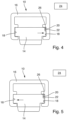
- Fig. 4 the slide rail 16 is in accordance with the Fig. 1 and 2 with the sliding block 14 provided therein, is shown again in an enlarged front view, in which the recess 26 of the sliding block 14 provided for the pressure element 20 can be seen more clearly.
- an arrow indicates a direction of force in which the sliding block 14 is supported on a guide surface 18 upon corresponding actuation of the drive.
- the recess 26 can be formed in the slide rail 16, and the sensor strip 22 can be arranged in the recess 26 of the slide rail 16, protected from the sliding block 14. The sliding block 14 can then be designed without the recess 26.
- Fig. 5 shows one with the Fig. 4 comparable front view of the slide rail 16 according to the Fig. 1 and 2 with a sliding block 14 provided therein, whereby the sliding block 14 is supported on an opposite guide surface 18 as a result of a reverse actuation of the drive.
- a force sensor strip extending at least partially in the longitudinal direction of the slide rail 16 or in the displacement direction of the slide block 14 can be provided on at least one, preferably on two opposing guide surfaces 18 of the slide rail 16, on which the slide block 14 is guided.
- the force sensor arranged between the sliding block 14 and the sliding rail 16 can detect the actuating forces exerted by the sliding block 14 on the sliding rail 16.
- the drive 10 can, for example, be designed as a door closer.
- the drive 10 according to the invention enables a simple and cost-effective detection of a particular sash opening angle. Furthermore, with the drive unit mounted on the sash, a respective cable transition is eliminated.
Landscapes
- Power-Operated Mechanisms For Wings (AREA)
- Transmission And Conversion Of Sensor Element Output (AREA)
Claims (12)
- Mécanisme d'entraînement (10) pour un ouvrant, en particulier une porte, une fenêtre ou un portail, comprenant une unité d'entraînement apte à être montée sur l'ouvrant ou sur un cadre fixe, avec un arbre de sortie qui est relié de manière fixe en rotation à l'une des deux extrémités d'un bras coulissant (12) qui est muni, à son autre extrémité, d'un coulisseau (14) guidé dans un rail (16) formant glissière monté sur le cadre fixe ou sur l'ouvrant,
caractérisé en ce que
le coulisseau (14) comprend, sur au moins un côté tourné vers la surface de guidage (18) du rail (16) formant glissière, s'étendant le long du rail (16) formant glissière, du côté tourné vers celui-ci, de préférence dans un évidement correspondant (26), au moins un élément de pression (20) préchargé élastiquement contre la surface de guidage (18), et, sur la surface de guidage (18) concernée, au moins partiellement, au moins une bande détectrice (22) sensible à la pression s'étendant dans la direction longitudinale du rail (16) formant glissière ou dans la direction de déplacement du coulisseau (14), apte à être sollicitée par l'élément de pression (20) préchargé élastiquement, qui est reliée fonctionnellement à une unité d'évaluation (24) pour déterminer la position respective du coulisseau (14) par rapport au rail (16) formant glissière au moyen de la pression exercée par l'élément de pression (20) sollicité élastiquement sur la bande détectrice (22) sensible à la pression. - Mécanisme d'entraînement selon la revendication 1,
caractérisé
en ce que la bande détectrice (22) sensible à la pression s'étend de manière continue sur au moins sensiblement toute la course du coulisseau (14). - Mécanisme d'entraînement selon l'une des revendications précédentes,
caractérisé
en ce qu'une bande détectrice respective (22) est réalisée sous la forme d'un potentiomètre à feuille sensible à la pression qui modifie sa tension locale sous l'effet d'une pression. - Mécanisme d'entraînement selon l'une des revendications précédentes,
caractérisé
en ce que, en particulier pour détecter un acte de vandalisme et/ou une surcharge et/ou la force de fermeture de l'entraînement (10), sur au moins une surface, de préférence sur deux surfaces de guidage (18) opposées l'une à l'autre, du rail (16) formant glissière, sur lesquelles le coulisseau (16) est guidé, il est prévu une bande détectrice de force s'étendant au moins partiellement dans la direction longitudinale du rail (16) formant glissière ou dans la direction de déplacement du coulisseau (14). - Mécanisme d'entraînement selon l'une des revendications précédentes,
caractérisé
en ce qu'au moins un élément de pression (20) du coulisseau (14), préchargé de manière élastique contre une surface de guidage (18) du rail (16) formant glissière, est réalisé sous forme de languette élastique. - Mécanisme d'entraînement selon la revendication 5,
caractérisé
en ce que la languette élastique (30) est réalisée sous la forme d'un élément moulé par injection sur le corps de base du coulisseau. - Mécanisme d'entraînement selon la revendication 5,
caractérisé
en ce que la languette élastique (30) est réalisée sous forme d'un élément en acier à ressort ou similaire, agencé sur le corps de base du coulisseau. - Mécanisme d'entraînement selon l'une des revendications précédentes,
caractérisé
en ce que ledit élément de pression (20) du coulisseau (14), qui est préchargé élastiquement contre une surface de guidage (18) du rail (16) formant glissière, est pourvu d'au moins un rouleau de pression rotatif (32) qui vient en engagement avec la bande détectrice (22). - Mécanisme d'entraînement selon l'une des revendications 1 à 5,
caractérisé
en ce qu'un élément de pression (20) du coulisseau (14), sollicité élastiquement contre une surface de guidage (18) du rail (16) formant glissière, comprend une pièce de pression (40) qui est disposée de manière déplaçable dans un alésage (36) du coulisseau (14) et qui est sollicitée élastiquement par un élément à ressort (38) en direction de la surface de guidage (18) du rail (16) formant glissière. - Mécanisme d'entraînement selon la revendication 9,
caractérisé
en ce que la précharge exercée sur la pièce de pression (40) par l'élément à ressort (38) est réglable au moyen d'une vis de réglage (42) agissant sur l'élément à ressort (38). - Mécanisme d'entraînement selon l'une des revendications précédentes,
caractérisé
en ce qu'au moins un rouleau de pression est monté de manière rotative directement sur le corps du coulisseau, en particulier pour mesurer les forces de pression qui apparaissent. - Mécanisme d'entraînement selon l'une des revendications précédentes,
caractérisé
en ce que le mécanisme d'entraînement (10) est réalisé sous la forme d'un ferme-porte.
Priority Applications (1)
| Application Number | Priority Date | Filing Date | Title |
|---|---|---|---|
| RS20250884A RS67173B1 (sr) | 2020-07-21 | 2021-07-21 | Pogon za krilo |
Applications Claiming Priority (1)
| Application Number | Priority Date | Filing Date | Title |
|---|---|---|---|
| DE102020209083.1A DE102020209083A1 (de) | 2020-07-21 | 2020-07-21 | Antrieb für einen Flügel |
Publications (2)
| Publication Number | Publication Date |
|---|---|
| EP3943702A1 EP3943702A1 (fr) | 2022-01-26 |
| EP3943702B1 true EP3943702B1 (fr) | 2025-06-18 |
Family
ID=77021126
Family Applications (1)
| Application Number | Title | Priority Date | Filing Date |
|---|---|---|---|
| EP21186910.2A Active EP3943702B1 (fr) | 2020-07-21 | 2021-07-21 | Entraînement pour un battant |
Country Status (5)
| Country | Link |
|---|---|
| EP (1) | EP3943702B1 (fr) |
| DE (1) | DE102020209083A1 (fr) |
| FI (1) | FI3943702T3 (fr) |
| PL (1) | PL3943702T3 (fr) |
| RS (1) | RS67173B1 (fr) |
Families Citing this family (1)
| Publication number | Priority date | Publication date | Assignee | Title |
|---|---|---|---|---|
| CN114883881B (zh) * | 2022-07-06 | 2022-09-13 | 四川东泉机械设备制造有限公司 | 一种滑触线系统 |
Family Cites Families (5)
| Publication number | Priority date | Publication date | Assignee | Title |
|---|---|---|---|---|
| DE10016984B4 (de) | 2000-04-06 | 2005-01-05 | Dorma Gmbh + Co. Kg | Vorrichtung zur Überwachung der Stellung eines Türflügels |
| DE20219720U1 (de) * | 2002-03-01 | 2003-03-20 | GEZE GmbH, 71229 Leonberg | Türantrieb |
| EP2269004A1 (fr) * | 2008-04-24 | 2011-01-05 | Hirschmann Automotive GmbH | Capteur de position magnétique comprenant une couche de contact en métal amorphe |
| DE102010017681A1 (de) * | 2010-07-01 | 2012-01-05 | Dorma Gmbh & Co Kg | Gleitgestänge-Schwenkflügelbetätiger |
| DE102012210592C5 (de) | 2012-06-22 | 2020-04-30 | Geze Gmbh | Automatische Drehtüranlage sowie Verfahren zum Betrieb einer automatischen Drehtüranlage |
-
2020
- 2020-07-21 DE DE102020209083.1A patent/DE102020209083A1/de active Pending
-
2021
- 2021-07-21 RS RS20250884A patent/RS67173B1/sr unknown
- 2021-07-21 FI FIEP21186910.2T patent/FI3943702T3/fi active
- 2021-07-21 EP EP21186910.2A patent/EP3943702B1/fr active Active
- 2021-07-21 PL PL21186910.2T patent/PL3943702T3/pl unknown
Also Published As
| Publication number | Publication date |
|---|---|
| RS67173B1 (sr) | 2025-09-30 |
| FI3943702T3 (fi) | 2025-08-08 |
| EP3943702A1 (fr) | 2022-01-26 |
| DE102020209083A1 (de) | 2022-01-27 |
| PL3943702T3 (pl) | 2025-10-20 |
Similar Documents
| Publication | Publication Date | Title |
|---|---|---|
| EP2033313B1 (fr) | Capteur de serrage | |
| EP2312102B1 (fr) | Dispositif pour la surveillance de l'état de fermeture d'une ferrure à crémone | |
| EP1936091A2 (fr) | Actionnement de porte ou de fenêtre | |
| EP0869250A2 (fr) | Dispositif pour détecter un coincement pour un élément de fermeture motorisé | |
| EP3943702B1 (fr) | Entraînement pour un battant | |
| WO2007124718A1 (fr) | Dispositif de protection antipincement commandé par capteur et véhicule associé | |
| EP1918890B1 (fr) | Dispositif destiné à l'affichage de l'état d'ouverture d'une fenêtre ou d'une porte | |
| EP1722060B1 (fr) | Unité fonctionnelle d'un véhicule automobile | |
| EP1818648A2 (fr) | Dispositif de mesure d'angle de rotation | |
| DE102011051336B3 (de) | Antriebseinrichtung | |
| EP2009215B1 (fr) | Dispositif de détection pour un dispositif d'entraînement des portes ou fenêtres | |
| DE102005054171B4 (de) | Verfahren und System zur Überwachung motorisch betriebener Fahrzeugkomponenten | |
| EP2354415B1 (fr) | Porte sectionnelle | |
| AT397871B (de) | Wegmesseinrichtung | |
| EP2281125B1 (fr) | Dispositif palier doté d'un capteur de position | |
| DE102018206583B4 (de) | Antriebseinheit für einen Schwenk- oder Schiebeflügel und Drehpositionserfassungsverfahren in einer Antriebseinheit | |
| DE10329045B4 (de) | Einrichtung zur Ermittlung mindestens einer Endlagenposition eines Antriebsgliedes, insbesondere eines druckmittelbetriebenen Linear- oder Drehantriebes | |
| DE102013108931A1 (de) | Vorrichtung zur Ansteuerung eines Antriebes | |
| DE4240503A1 (de) | Kunststoff- oder Aluminiumfenster mit einem Rahmen aus extrudierten oder gepreßten Hohlprofilen | |
| DE102007002945B4 (de) | Vorrichtung und Verfahren zum Erkennen der Position eines Schließelements | |
| DE202014001263U1 (de) | Vorrichtung zum Bestimmen eines Öffnungswinkels eines Türblatts und optischer Sensor | |
| DE202008006295U1 (de) | Lesekopf für ein Längenmesssystem und Längenmesssystem | |
| DE10252205A1 (de) | Vorrichtung zur Positionserfassung einer Tür | |
| DE102006036102B4 (de) | Winkelgeber mit Montageöffnung | |
| EP1448863B1 (fr) | Systeme de deplacement d'un element |
Legal Events
| Date | Code | Title | Description |
|---|---|---|---|
| PUAI | Public reference made under article 153(3) epc to a published international application that has entered the european phase |
Free format text: ORIGINAL CODE: 0009012 |
|
| STAA | Information on the status of an ep patent application or granted ep patent |
Free format text: STATUS: THE APPLICATION HAS BEEN PUBLISHED |
|
| AK | Designated contracting states |
Kind code of ref document: A1 Designated state(s): AL AT BE BG CH CY CZ DE DK EE ES FI FR GB GR HR HU IE IS IT LI LT LU LV MC MK MT NL NO PL PT RO RS SE SI SK SM TR |
|
| STAA | Information on the status of an ep patent application or granted ep patent |
Free format text: STATUS: REQUEST FOR EXAMINATION WAS MADE |
|
| 17P | Request for examination filed |
Effective date: 20220704 |
|
| RBV | Designated contracting states (corrected) |
Designated state(s): AL AT BE BG CH CY CZ DE DK EE ES FI FR GB GR HR HU IE IS IT LI LT LU LV MC MK MT NL NO PL PT RO RS SE SI SK SM TR |
|
| P01 | Opt-out of the competence of the unified patent court (upc) registered |
Effective date: 20230510 |
|
| GRAP | Despatch of communication of intention to grant a patent |
Free format text: ORIGINAL CODE: EPIDOSNIGR1 |
|
| STAA | Information on the status of an ep patent application or granted ep patent |
Free format text: STATUS: GRANT OF PATENT IS INTENDED |
|
| RIC1 | Information provided on ipc code assigned before grant |
Ipc: E05F 15/63 20150101AFI20250224BHEP |
|
| INTG | Intention to grant announced |
Effective date: 20250310 |
|
| GRAS | Grant fee paid |
Free format text: ORIGINAL CODE: EPIDOSNIGR3 |
|
| GRAA | (expected) grant |
Free format text: ORIGINAL CODE: 0009210 |
|
| STAA | Information on the status of an ep patent application or granted ep patent |
Free format text: STATUS: THE PATENT HAS BEEN GRANTED |
|
| AK | Designated contracting states |
Kind code of ref document: B1 Designated state(s): AL AT BE BG CH CY CZ DE DK EE ES FI FR GB GR HR HU IE IS IT LI LT LU LV MC MK MT NL NO PL PT RO RS SE SI SK SM TR |
|
| REG | Reference to a national code |
Ref country code: GB Ref legal event code: FG4D Free format text: NOT ENGLISH |
|
| REG | Reference to a national code |
Ref country code: CH Ref legal event code: EP |
|
| REG | Reference to a national code |
Ref country code: DE Ref legal event code: R096 Ref document number: 502021007757 Country of ref document: DE |
|
| REG | Reference to a national code |
Ref country code: CH Ref legal event code: EP |
|
| REG | Reference to a national code |
Ref country code: IE Ref legal event code: FG4D Free format text: LANGUAGE OF EP DOCUMENT: GERMAN |
|
| REG | Reference to a national code |
Ref country code: FI Ref legal event code: FGE |
|
| PGFP | Annual fee paid to national office [announced via postgrant information from national office to epo] |
Ref country code: FI Payment date: 20250822 Year of fee payment: 5 |
|
| PGFP | Annual fee paid to national office [announced via postgrant information from national office to epo] |
Ref country code: DE Payment date: 20250731 Year of fee payment: 5 |
|
| REG | Reference to a national code |
Ref country code: LT Ref legal event code: MG9D |
|
| PG25 | Lapsed in a contracting state [announced via postgrant information from national office to epo] |
Ref country code: NO Free format text: LAPSE BECAUSE OF FAILURE TO SUBMIT A TRANSLATION OF THE DESCRIPTION OR TO PAY THE FEE WITHIN THE PRESCRIBED TIME-LIMIT Effective date: 20250918 Ref country code: GR Free format text: LAPSE BECAUSE OF FAILURE TO SUBMIT A TRANSLATION OF THE DESCRIPTION OR TO PAY THE FEE WITHIN THE PRESCRIBED TIME-LIMIT Effective date: 20250919 |
|
| PG25 | Lapsed in a contracting state [announced via postgrant information from national office to epo] |
Ref country code: BG Free format text: LAPSE BECAUSE OF FAILURE TO SUBMIT A TRANSLATION OF THE DESCRIPTION OR TO PAY THE FEE WITHIN THE PRESCRIBED TIME-LIMIT Effective date: 20250618 |
|
| PG25 | Lapsed in a contracting state [announced via postgrant information from national office to epo] |
Ref country code: HR Free format text: LAPSE BECAUSE OF FAILURE TO SUBMIT A TRANSLATION OF THE DESCRIPTION OR TO PAY THE FEE WITHIN THE PRESCRIBED TIME-LIMIT Effective date: 20250618 |
|
| PGFP | Annual fee paid to national office [announced via postgrant information from national office to epo] |
Ref country code: AT Payment date: 20251020 Year of fee payment: 5 Ref country code: FR Payment date: 20250812 Year of fee payment: 5 |
|
| PGFP | Annual fee paid to national office [announced via postgrant information from national office to epo] |
Ref country code: RS Payment date: 20250711 Year of fee payment: 5 |
|
| REG | Reference to a national code |
Ref country code: NL Ref legal event code: MP Effective date: 20250618 |
|
| PG25 | Lapsed in a contracting state [announced via postgrant information from national office to epo] |
Ref country code: LV Free format text: LAPSE BECAUSE OF FAILURE TO SUBMIT A TRANSLATION OF THE DESCRIPTION OR TO PAY THE FEE WITHIN THE PRESCRIBED TIME-LIMIT Effective date: 20250618 |
|
| PG25 | Lapsed in a contracting state [announced via postgrant information from national office to epo] |
Ref country code: NL Free format text: LAPSE BECAUSE OF FAILURE TO SUBMIT A TRANSLATION OF THE DESCRIPTION OR TO PAY THE FEE WITHIN THE PRESCRIBED TIME-LIMIT Effective date: 20250618 |
|
| PG25 | Lapsed in a contracting state [announced via postgrant information from national office to epo] |
Ref country code: PT Free format text: LAPSE BECAUSE OF FAILURE TO SUBMIT A TRANSLATION OF THE DESCRIPTION OR TO PAY THE FEE WITHIN THE PRESCRIBED TIME-LIMIT Effective date: 20251020 |
|
| PG25 | Lapsed in a contracting state [announced via postgrant information from national office to epo] |
Ref country code: IS Free format text: LAPSE BECAUSE OF FAILURE TO SUBMIT A TRANSLATION OF THE DESCRIPTION OR TO PAY THE FEE WITHIN THE PRESCRIBED TIME-LIMIT Effective date: 20251018 |
|
| PG25 | Lapsed in a contracting state [announced via postgrant information from national office to epo] |
Ref country code: SM Free format text: LAPSE BECAUSE OF FAILURE TO SUBMIT A TRANSLATION OF THE DESCRIPTION OR TO PAY THE FEE WITHIN THE PRESCRIBED TIME-LIMIT Effective date: 20250618 |
|
| PG25 | Lapsed in a contracting state [announced via postgrant information from national office to epo] |
Ref country code: CZ Free format text: LAPSE BECAUSE OF FAILURE TO SUBMIT A TRANSLATION OF THE DESCRIPTION OR TO PAY THE FEE WITHIN THE PRESCRIBED TIME-LIMIT Effective date: 20250618 |
|
| PGFP | Annual fee paid to national office [announced via postgrant information from national office to epo] |
Ref country code: PL Payment date: 20250807 Year of fee payment: 5 |
|
| PG25 | Lapsed in a contracting state [announced via postgrant information from national office to epo] |
Ref country code: EE Free format text: LAPSE BECAUSE OF FAILURE TO SUBMIT A TRANSLATION OF THE DESCRIPTION OR TO PAY THE FEE WITHIN THE PRESCRIBED TIME-LIMIT Effective date: 20250618 |
|
| PG25 | Lapsed in a contracting state [announced via postgrant information from national office to epo] |
Ref country code: RO Free format text: LAPSE BECAUSE OF FAILURE TO SUBMIT A TRANSLATION OF THE DESCRIPTION OR TO PAY THE FEE WITHIN THE PRESCRIBED TIME-LIMIT Effective date: 20250618 Ref country code: SK Free format text: LAPSE BECAUSE OF FAILURE TO SUBMIT A TRANSLATION OF THE DESCRIPTION OR TO PAY THE FEE WITHIN THE PRESCRIBED TIME-LIMIT Effective date: 20250618 |
|
| PG25 | Lapsed in a contracting state [announced via postgrant information from national office to epo] |
Ref country code: ES Free format text: LAPSE BECAUSE OF FAILURE TO SUBMIT A TRANSLATION OF THE DESCRIPTION OR TO PAY THE FEE WITHIN THE PRESCRIBED TIME-LIMIT Effective date: 20250618 |
|
| REG | Reference to a national code |
Ref country code: CH Ref legal event code: H13 Free format text: ST27 STATUS EVENT CODE: U-0-0-H10-H13 (AS PROVIDED BY THE NATIONAL OFFICE) Effective date: 20260224 |
|
| PG25 | Lapsed in a contracting state [announced via postgrant information from national office to epo] |
Ref country code: LU Free format text: LAPSE BECAUSE OF NON-PAYMENT OF DUE FEES Effective date: 20250721 |
|
| REG | Reference to a national code |
Ref country code: BE Ref legal event code: MM Effective date: 20250731 |
|
| PG25 | Lapsed in a contracting state [announced via postgrant information from national office to epo] |
Ref country code: MC Free format text: LAPSE BECAUSE OF FAILURE TO SUBMIT A TRANSLATION OF THE DESCRIPTION OR TO PAY THE FEE WITHIN THE PRESCRIBED TIME-LIMIT Effective date: 20250618 |
|
| PG25 | Lapsed in a contracting state [announced via postgrant information from national office to epo] |
Ref country code: DK Free format text: LAPSE BECAUSE OF FAILURE TO SUBMIT A TRANSLATION OF THE DESCRIPTION OR TO PAY THE FEE WITHIN THE PRESCRIBED TIME-LIMIT Effective date: 20250618 |
|
| PG25 | Lapsed in a contracting state [announced via postgrant information from national office to epo] |
Ref country code: IT Free format text: LAPSE BECAUSE OF FAILURE TO SUBMIT A TRANSLATION OF THE DESCRIPTION OR TO PAY THE FEE WITHIN THE PRESCRIBED TIME-LIMIT Effective date: 20250618 Ref country code: BE Free format text: LAPSE BECAUSE OF NON-PAYMENT OF DUE FEES Effective date: 20250731 |
|
| PLBE | No opposition filed within time limit |
Free format text: ORIGINAL CODE: 0009261 |
|
| STAA | Information on the status of an ep patent application or granted ep patent |
Free format text: STATUS: NO OPPOSITION FILED WITHIN TIME LIMIT |