EP1448863B1 - Systeme de deplacement d'un element - Google Patents
Systeme de deplacement d'un element Download PDFInfo
- Publication number
- EP1448863B1 EP1448863B1 EP01274868A EP01274868A EP1448863B1 EP 1448863 B1 EP1448863 B1 EP 1448863B1 EP 01274868 A EP01274868 A EP 01274868A EP 01274868 A EP01274868 A EP 01274868A EP 1448863 B1 EP1448863 B1 EP 1448863B1
- Authority
- EP
- European Patent Office
- Prior art keywords
- resistance
- conductors
- electrical conductors
- stop bar
- resistance value
- Prior art date
- Legal status (The legal status is an assumption and is not a legal conclusion. Google has not performed a legal analysis and makes no representation as to the accuracy of the status listed.)
- Expired - Lifetime
Links
- 239000004020 conductor Substances 0.000 claims description 48
- 238000005259 measurement Methods 0.000 claims description 3
- 230000006835 compression Effects 0.000 claims 1
- 238000007906 compression Methods 0.000 claims 1
- 230000003247 decreasing effect Effects 0.000 claims 1
- 230000007423 decrease Effects 0.000 description 5
- 238000007789 sealing Methods 0.000 description 4
- 230000006378 damage Effects 0.000 description 3
- 230000001419 dependent effect Effects 0.000 description 3
- 238000001514 detection method Methods 0.000 description 3
- 230000002349 favourable effect Effects 0.000 description 3
- 238000000034 method Methods 0.000 description 3
- 208000027418 Wounds and injury Diseases 0.000 description 2
- 238000013459 approach Methods 0.000 description 2
- 238000010586 diagram Methods 0.000 description 2
- 208000014674 injury Diseases 0.000 description 2
- 239000000463 material Substances 0.000 description 2
- 230000006978 adaptation Effects 0.000 description 1
- 238000011161 development Methods 0.000 description 1
- 230000018109 developmental process Effects 0.000 description 1
- 238000006073 displacement reaction Methods 0.000 description 1
- 230000010354 integration Effects 0.000 description 1
- 238000004519 manufacturing process Methods 0.000 description 1
- 239000002184 metal Substances 0.000 description 1
- 230000001681 protective effect Effects 0.000 description 1
- 230000009885 systemic effect Effects 0.000 description 1
Images


Classifications
-
- E—FIXED CONSTRUCTIONS
- E05—LOCKS; KEYS; WINDOW OR DOOR FITTINGS; SAFES
- E05F—DEVICES FOR MOVING WINGS INTO OPEN OR CLOSED POSITION; CHECKS FOR WINGS; WING FITTINGS NOT OTHERWISE PROVIDED FOR, CONCERNED WITH THE FUNCTIONING OF THE WING
- E05F15/00—Power-operated mechanisms for wings
- E05F15/40—Safety devices, e.g. detection of obstructions or end positions
- E05F15/42—Detection using safety edges
- E05F15/44—Detection using safety edges responsive to changes in electrical conductivity
- E05F15/443—Detection using safety edges responsive to changes in electrical conductivity specially adapted for vehicle windows or roofs
-
- E—FIXED CONSTRUCTIONS
- E05—LOCKS; KEYS; WINDOW OR DOOR FITTINGS; SAFES
- E05Y—INDEXING SCHEME ASSOCIATED WITH SUBCLASSES E05D AND E05F, RELATING TO CONSTRUCTION ELEMENTS, ELECTRIC CONTROL, POWER SUPPLY, POWER SIGNAL OR TRANSMISSION, USER INTERFACES, MOUNTING OR COUPLING, DETAILS, ACCESSORIES, AUXILIARY OPERATIONS NOT OTHERWISE PROVIDED FOR, APPLICATION THEREOF
- E05Y2900/00—Application of doors, windows, wings or fittings thereof
- E05Y2900/50—Application of doors, windows, wings or fittings thereof for vehicles
- E05Y2900/53—Type of wing
- E05Y2900/55—Windows
Definitions
- the invention relates to a system for adjusting a part which is rotatable or tiltable by motor against at least one stop bar according to the preamble of the independent claim.
- a drive device for a movable part which opens and closes, for example, a soausstellpper a vehicle.
- the Theausstellrous is hinged to a chassis, such as the B-pillar of the vehicle and can be moved by means of an electric motor actuator from its closed position to the open position and back again.
- the electric motor is connected via a reduction gear, which drives a drive shaft, by means of a ball head at the end of the drive shaft and a corresponding ball socket with the 10.
- a anti-pinch sensor which detects the pinching of an obstacle in a closable opening.
- a motor vehicle sliding roof or window is moved with an edge on a switching strip, which is aligned parallel to the edge of the part as a moving part. If the safety edge is pressure-loaded at one point, a voltage signal tapped on the safety edge abruptly rises, whereby a pinching-in event is detected.
- the system according to the invention with the features of the main claim has the advantage that the pinching of an object or body part in a motor-operated soausstellpper is detected in good time by a arranged along the stop bar anti-trap sensor.
- a risk of injury by pinching can be effectively prevented.
- the anti-pinch sensor along the stop bar has two electrical conductors, with a predetermined resistance. Their resistance preferably changes as a function of their length.
- the pressure point is identified locally along the stop bar and thus enables a distinction between an entrapment event and a normal closing operation.
- the stop bar should therefore not have a certain elasticity fall below, so as to ensure that a localized pressure point on the one hand during the closing process, on the other hand arises in Einklemmfall.
- the resistance is measured between the two open conductor ends at the opposite end of the electrical contact.
- This measured resistance value continuously decreases during trouble-free closing of the opening window, so that the resistance measuring curve of the normal closing operation can be separated from the resistance measurement value of a pinching event.
- the pressure point moves along the stop bar on the side of the joints or axis less quickly than on the side with the open conductor ends in almost closed state. Therefore, it is particularly favorable that the resistance of the electrical conductors, starting from the open ends at the resistance tap toward the side of the window joints, increases disproportionately. As a result, a higher, more uniform spatial resolution of the pressure point over the entire stop bar can be achieved.
- the systemic determination of the closing position of the window by means of the measured resistance value allows a controlled opening and closing of the window. Likewise, a trouble-free approach to any intermediate position is possible. On an additional position sensors (Hall sensors) for the adjustment can be dispensed with.
- the detection of the Einklemmposition offers the ability to determine the closing force at the Einklemmposition over the distance to the window hinges.
- the motor can advantageously be stopped and / or reversed as a function of a closing force limit value.
- the system makes it possible to determine the thickness of the Einklemmurgistandes, so that it can be concluded that the nature of the clamped body part.
- the motor can be reversed faster than, for example, in the case of an arm. If, at the same time, the force to be applied by the drive during the closing operation is measured, the type of clamping object can be determined more precisely from the determined thickness of the clamping object, as well as the observed force increase. That is, the error rate is reduced by the adaptation of the anti-jamming to the thickness and thus to the suspected nature of the Einklemmurgistandes.
- an elastic conductive plastic between the two parallel electrical conductors. Now presses the disc or the clamped object against the stop bar, this plastic is compressed and reduces its resistance.
- This principle corresponds to the electrical contact in the first embodiment, but offers the advantage that the two electrical conductors go back exactly to their original position when the window is opened or the trapped object is removed.
- This Deformable conductive plastic creates reproducible conditions and is inexpensive to manufacture.
- the elastic properties of the plastic also enable a closing force-dependent release of the anti-pinch protection.
- An advantage is the arrangement of the electrical conductors within an elastic hollow profile, as they are protected from dirt and the weather. Due to the elasticity of the hollow profile is also ensured that the two conductors go back to their original position when no pressure is exerted on the stop bar.
- the anti-pinch sensor assumes the function of a sealing ring or is integrated in a seal in order to ensure watertight and burglar-proof closing of the side-opening window.
- Such a combined solution is inexpensive, saves space on the window frame and does not require any structural changes.
- the anti-pinch sensor Due to the continuous measurement of the resistance between the two conductor ends, the anti-pinch sensor is constantly checked for its functionality. A cable break or short circuit is immediately detected and indicated that the anti-trap protection is disabled.
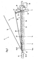
- FIG. 1 shows an embodiment of a system for adjusting a soausstellppers in section
- Figures 2a and 2b are each a diagram of the resistance at the trouble-free closing of the Soausstellmens and Einklemmfall the system of Figure 1
- Figures 3a - 3c are each cross-sections of different variants of an anti-trap sensor according to Figure 1.
- FIG. 1 shows an inventive system for adjusting a soausstellppers 9, in which a disc 10 is fixed by means of joints 12 or a rotation axis 14 on the frame 16 of the window, for example the B-pillar of a motor vehicle.
- the disc 10 can be by means of a motor 18 which is operatively connected via a ball head 22 of a threaded spindle 20 with a mounted on the disc 10 ball socket 24 move. To adjust the disc 10, it is rotated about the axis of rotation 14 against a stop 26, so that the disc 10 closes scissor-like.
- the joints 12 are designed in such a way that the disc 10 also experiences a translational movement during opening and closing in addition to the rotational movement, this is referred to as tilting against the stop bar 26.
- a pinch protection sensor 28 which has substantially two parallel electrical conductor 30 extending at a small distance from each other.
- the electrical conductors 30 are formed as metal wires of constant cross-section, so that their total resistance increases in proportion to their length 32.
- the two conductors 30 are connected together at their ends 34 at the joints.
- between the two open ends 36 of the conductor 30 by means of an ohmmeter 38 continuously measured their resistance and the measured value of a control unit 39 is supplied, which drives the motor 18.
- the start value 44 of the open-window resistance corresponds to the total resistance of the two connected conductors 30 If the two conductors 30 are short-circuited over their entire length 32, the measured resistance approaches zero. If, for example, the open end 34 of the two conductors 30 were left open, the start value 44 of the resistor would be infinite with the window 9 open and would only jump to the starting value 44 of the resistor when the two conductors 30 were compressed at the beginning of the closing process.
- the measured resistance curve allows a clear assignment of the pressure point 40 to a position on the anti-jamming sensor 28. However, this function is not identical to the measured resistance value with respect to the adjustment path of the disc 10 along the threaded spindle 20. This function shows a much lower resistance change in the almost open Window 9 compared to the almost closed window 9.
- the two conductors 30 may be formed such that their resistance increases depending on the length 32 to the closed ends 34 out disproportionately. This is most easily realized by a tapering of the conductor cross-section 46 (see FIGS. 3a-3c) towards the joints 12. Another possibility is to modify the conductor material so that its resistivity continuously increases towards the joints 12. As a result, a uniform position resolution relative to the displacement along the threaded spindle 20 can be achieved.
- the adjustment of the spindle 20 is proportional to the time in the simplest case.
- a corresponding curve 43 of the measured resistance value is shown by dashed lines in FIG. 2a. It clearly shows the disproportionate increase in the resistance with the length 32 of the conductor 30.
- the resistance 46 which varies according to the jump discontinuous 47 sets corresponds to a position on the anti-jamming sensor 28 of the undisturbed closing curve and thus indicates the position of the pinching event l E on.
- the amount 49 of the resistor drop 47 corresponds to a certain distance along the anti-pinch sensor 28 during undisturbed closing. With known angular geometry of the Ausstellmakers 9 this path is directly a measure of the thickness of the trapped object 45. This information can process the control unit 39 for determining the tripping threshold for stopping / reversing the motor 18.
- FIGS. 3 a to c show different variants of the anti-pinch sensor 28 in cross section.
- the two electrical conductors 30 are arranged parallel within an elastic hollow profile 48, for example of fabric-reinforced rubber.
- the hollow profile 48 must be so elastic that the disc 10 or the trapped object 45 in the direction of arrow 50 only ever selectively make an electrical contact 42 along the anti-pinch sensor 28.
- the hollow profile 48 must be so rigid that it puts the two conductors 30 after removal of the external pressure again reproducible in their original position.
- a T-double profile 52 is mounted, which engages in a corresponding profile in the window frame 16.
- the two conductors 30 are replaced with a circular cross section 53 by two conductors 30 with a flat, rectangular cross-section 54, which are connected to each other by means of an electrically conductive, deformable plastic 56.
- This plastic 56 has a relatively high electrical resistance in the pressure-free state. If the disk 10 or the object 45 presses along the arrow 50 against this anti-pinch sensor 28, the plastic 56 becomes compressed. In this case, its resistance decreases considerably, so that this reduction in resistance corresponds to the generation of an electrical contact 42.
- the conductive plastic 56 also has the property that it takes under pressure relief again its old form and its original resistance value.
- the plastic 56 and a surrounding protective sheath 58 is such that the electrical contact 42 between the two conductors 30 with a flat, rectangular cross-section 54 occurs only selectively in the longitudinal direction along the anti-pinch sensor 28.
- the anti-pinch sensor 28 of FIG. 3b is disposed within a sealing profile 60 shown in FIG. 3c.
- the material of the seal 60 is optimized with respect to its sealing properties, the conductive plastic 56 with respect to its resistance reduction.
- the shape of the seal 60 is adapted to the shape of the frame 16 and the disc 10. Likewise, however, a direct integration of the electrical conductors 30 in the sealing profile 60 is possible, as shown in Figure 3a.
- the control unit 39 detects when one of the two conductors 30 is broken, since then sets an approximately infinite resistance of the anti-pinch sensor 28. It is also monitored whether the two conductors 30 when opening and removing the jammed object 45 return to their original position by the measured resistance is compared with the recorded reference curve of the undisturbed closing operation.
- Such an anti-jamming sensor 28 is included a soausstellari 9 of a motor vehicle ideally installed on the upper and lower stop bar 26. For a vertical stop bar no spatially resolved detection of a pinching event is necessary because here the disc 10 presses on the entire length of the stop bar only immediately before the closed state against the stop bar. Nevertheless, the same anti-pinch sensor 28 can also be used for this bar and linked accordingly via the control unit 39.
- the system for adjusting a rotatable or tiltable part is not limited to motor vehicles.
- the resistance between the open ends 36 of the two conductors 30 is measured.
- the decrease in resistance is checked for continuity or compared to a reference curve.
- smoothly closing the resistance value is associated with a follower closing position 1 S of the disc 10.
- a sudden resistance drop 47 occurs, the motor 18 is stopped and / or ridden.
- the amount 49 of the resistor drop 47 is measured and from this the pinching position l E of the object 45 is determined. From the difference of the closed position l S of the disc 10 and Einklemmposition l E of the article 45, the thickness thereof is determined. The Einklemmposition l E and the thickness are used to determine the release threshold of the anti-trap. When an approximate infinite resistance occurs, it indicates that the anti-trap protection is not functional.
Landscapes
- Window Of Vehicle (AREA)
- Power-Operated Mechanisms For Wings (AREA)
Claims (13)
- Système de déplacement d'un élément (10), notamment d'une vitre orientable latérale (10) d'un véhicule automobile, qui peut tourner ou basculer par l'action d'un moteur autour d'une articulation (12) par rapport à au moins une barrette de butée (26), le long de laquelle est disposé un détecteur anti-pincement (28), la valeur mesurée de la résistance du détecteur (28) décroissant en continu pendant la fermeture sans gêne de l'élément (10), tandis qu'au contraire, la survenance soudaine d'une résistance est détectée comme un cas de pincement.
- Système selon la revendication 1,
caractérisé en ce que
le détecteur anti-pincement (28) présente deux conducteurs électriques (30) essentiellement parallèles et espacés, et dont la résistance augmente selon une fonction de leur longueur (32). - Système selon la revendication 2,
caractérisé en ce que
l'élément (10), quand il se ferme, vient s'appliquer sur la bordure de butée (26), et les deux conducteurs électriques (30) sont poussés l'un vers l'autre de manière que s'établisse un contact électrique (42). - Système selon une des revendications 1 à 3,
caractérisé en ce qu
aux extrémités (36) des conducteurs (10) situées à l'opposé de l'articulation (12), la résistance entre ces deux conducteurs est saisie, et au cours de la fermeture de l'élément, le contact électrique (42), c'est-à-dire le point de pression (40) entre les deux conducteurs électriques (30) se déplace des extrémités (34) des conducteurs (30) situées sur l'articulation (12), vers les extrémités opposées (36) de ces conducteurs (30). - Système selon la revendication 4,
caractérisé en ce que
la résistance des conducteurs électriques (30), en partant de leurs extrémités situées sur le point de saisie de la résistance (36), croît en fonction de leur longueur (32) plus que proportionnellement. - Système selon la revendication 4 ou 5,
caractérisé en ce que
la valeur de la mesure et de la résistance correspond, en cas de fermeture sans gêne, à une position de fermeture définie de l'élément (10). - Système selon une des revendications 4 à 6,
caractérisé en ce que
quand la valeur mesurée de la résistance décroît en faisant un saut (47), le moteur (18) est arrêté et/ou son mouvement est inversé. - Système selon la revendication 7,
caractérisé en ce que
la valeur mesurée (46) de la résistance, après sa chute (47), indique la position d'un objet (45) pincé. - Système selon la revendication 7 ou 8,
caractérisé en ce qu'
à partir du niveau (49) de la valeur de la résistance en une position définie, l'épaisseur de l'objet pincé (45) est établie. - Système selon une des revendications 2 à 9,
caractérisé en ce qu'
entre les deux conducteurs électriques parallèles et espacés (30), est disposée une matière plastique (46) déformable et conductrice, dont la résistance diminue quand elle est comprimée. - Système selon une des revendications 2 à 10,
caractérisé en ce que
les deux conducteurs (30) parallèles et espacés sont disposés à l'intérieur d'un profilé creux (48) élastique. - Système selon une des revendications 1 à 11,
caractérisé en ce que
le détecteur anti-pincement (28) est réalisé sous la forme d'un joint d'étanchéité (60) ou intégré à un tel joint (60). - Système selon une des revendications 1 à 12,
caractérisé en ce que
la capacité de fonctionnement du détecteur anti-pincement (28) est contrôlée en permanence par l'intermédiaire d'une mesure continue de la résistance.
Applications Claiming Priority (1)
| Application Number | Priority Date | Filing Date | Title |
|---|---|---|---|
| PCT/DE2001/004354 WO2003048491A1 (fr) | 2001-11-20 | 2001-11-20 | Systeme de deplacement d'un element |
Publications (2)
| Publication Number | Publication Date |
|---|---|
| EP1448863A1 EP1448863A1 (fr) | 2004-08-25 |
| EP1448863B1 true EP1448863B1 (fr) | 2007-05-30 |
Family
ID=5648314
Family Applications (1)
| Application Number | Title | Priority Date | Filing Date |
|---|---|---|---|
| EP01274868A Expired - Lifetime EP1448863B1 (fr) | 2001-11-20 | 2001-11-20 | Systeme de deplacement d'un element |
Country Status (5)
| Country | Link |
|---|---|
| EP (1) | EP1448863B1 (fr) |
| JP (1) | JP4106334B2 (fr) |
| AU (1) | AU2002215865A1 (fr) |
| DE (1) | DE10197164D2 (fr) |
| WO (1) | WO2003048491A1 (fr) |
Cited By (1)
| Publication number | Priority date | Publication date | Assignee | Title |
|---|---|---|---|---|
| DE102021108375A1 (de) | 2021-04-01 | 2022-10-06 | Dr. Ing. H.C. F. Porsche Aktiengesellschaft | Fahrzeugtür, Verfahren zu deren Herstellung und entsprechendes Fahrzeug |
Families Citing this family (1)
| Publication number | Priority date | Publication date | Assignee | Title |
|---|---|---|---|---|
| FR2884764B1 (fr) * | 2005-04-26 | 2007-07-27 | Peugeot Citroen Automobiles Sa | Vehicule automobile a vitres de custode ameliorees |
Family Cites Families (5)
| Publication number | Priority date | Publication date | Assignee | Title |
|---|---|---|---|---|
| DE4201019C2 (de) * | 1992-01-16 | 1993-10-21 | Daimler Benz Ag | Vorrichtung zum Vermeiden von Unfällen beim Annähern einer durch einen Antrieb beweglichen Tafel an eine Schließkante |
| LU90046B1 (de) * | 1997-04-04 | 1998-10-05 | Iee Sarl | Vorrichtung zur Einklemmerkennung bei einem kraftbetaetigten Schliesselement |
| US6246194B1 (en) * | 1999-09-07 | 2001-06-12 | Meritor Light Vehicle Systems, Inc. | Method and system for detecting an object in an automotive window |
| DE10002466B4 (de) * | 2000-01-21 | 2004-11-04 | Brose Fahrzeugteile Gmbh & Co. Kg, Coburg | Verfahren zum Verstellen einer Fensterscheibe eines Kraftfahrzeugs mit Einklemmschutz, insbesondere einer Fensterscheibe eines Cabriolets sowie eine Vorrichtung zur Durchführung des Verfahrens |
| US6297605B1 (en) * | 2000-03-07 | 2001-10-02 | Daimlerchrysler Corporation | Pinch sensing arrangement for a motor vehicle power liftgate |
-
2001
- 2001-11-20 AU AU2002215865A patent/AU2002215865A1/en not_active Abandoned
- 2001-11-20 JP JP2003549659A patent/JP4106334B2/ja not_active Expired - Fee Related
- 2001-11-20 WO PCT/DE2001/004354 patent/WO2003048491A1/fr not_active Ceased
- 2001-11-20 DE DE10197164T patent/DE10197164D2/de not_active Expired - Fee Related
- 2001-11-20 EP EP01274868A patent/EP1448863B1/fr not_active Expired - Lifetime
Cited By (2)
| Publication number | Priority date | Publication date | Assignee | Title |
|---|---|---|---|---|
| DE102021108375A1 (de) | 2021-04-01 | 2022-10-06 | Dr. Ing. H.C. F. Porsche Aktiengesellschaft | Fahrzeugtür, Verfahren zu deren Herstellung und entsprechendes Fahrzeug |
| DE102021108375B4 (de) | 2021-04-01 | 2023-06-07 | Dr. Ing. H.C. F. Porsche Aktiengesellschaft | Fahrzeugtür, Verfahren zu deren Herstellung und entsprechendes Fahrzeug |
Also Published As
| Publication number | Publication date |
|---|---|
| DE10197164D2 (de) | 2004-09-23 |
| JP4106334B2 (ja) | 2008-06-25 |
| EP1448863A1 (fr) | 2004-08-25 |
| JP2005511924A (ja) | 2005-04-28 |
| AU2002215865A1 (en) | 2003-06-17 |
| WO2003048491A1 (fr) | 2003-06-12 |
Similar Documents
| Publication | Publication Date | Title |
|---|---|---|
| EP3325748B1 (fr) | Élément de porte muni d'un dispositif amortisseur pilotable | |
| WO2004038149A2 (fr) | Capteur a mesure capacitive et ensemble de capteurs capacitifs pour la detection d'une situation de coinçage | |
| DE19758796B4 (de) | Verfahren zur Steuerung und Regelung der Verstellbewegung eines translatorisch verstellbaren Bauteils in Fahrzeugen | |
| DE19816736C2 (de) | Betätigungsvorrichtung für Kraftfahrzeugtüren | |
| EP0988678B1 (fr) | Procede et dispositif pour commander un systeme de toit ouvrant coulissant | |
| WO2018007510A1 (fr) | Dispositif de sécurité antipincement conçu pour une porte latérale de véhicule automobile | |
| EP2330271B1 (fr) | Agencement de surveillance de capteur et joint d'une porte porte pivotante coulissante | |
| DE4201019C2 (de) | Vorrichtung zum Vermeiden von Unfällen beim Annähern einer durch einen Antrieb beweglichen Tafel an eine Schließkante | |
| EP1915500B1 (fr) | Dispositif anticoincement dans le domaine automobile | |
| WO2007124718A1 (fr) | Dispositif de protection antipincement commandé par capteur et véhicule associé | |
| DE102021201049B4 (de) | Verfahren zur motorischen Bewegungsunterstützung oder Bremsung einer Fahrzeugtür | |
| DE3724942A1 (de) | Sicherheitsvorrichtung | |
| DE19911592C2 (de) | Manuell betätigtes Antriebssystem für ein motorisch verstellbares Schließteil eines Fahrzeugs | |
| EP1448863B1 (fr) | Systeme de deplacement d'un element | |
| WO2007131473A1 (fr) | Dispositif pour commander un hayon de véhicule | |
| DE69513913T2 (de) | Sicherheitssystem und zugehöriger Detektor | |
| DE10054483A1 (de) | System zum Verstellen eines Teils | |
| DE10151840A1 (de) | Vorrichtung und Verfahren zum Verstellen eines Teils | |
| DE102017201464A1 (de) | Sensoreinheit für eine Einklemmschutzvorrichtung | |
| DE102005043534B4 (de) | Einklemmschutzvorrichtung im Kraftfahrzeugbereich | |
| DE10130344A1 (de) | Einklemmschutzvorrichtung | |
| DE102004015296B4 (de) | Einklemmschutz für ein öffnungsfähiges Fahrzeugdach | |
| DE102009008366B3 (de) | Elektromotorisches Schließsystem mit Einklemmschutz | |
| DE102020213589B4 (de) | Verfahren zum Steuern einer vorzugsweise elektrischen Schiebetür | |
| DE102005042633B4 (de) | Verfahren zum Überprüfen einer Einklemmschutzvorrichtung |
Legal Events
| Date | Code | Title | Description |
|---|---|---|---|
| PUAI | Public reference made under article 153(3) epc to a published international application that has entered the european phase |
Free format text: ORIGINAL CODE: 0009012 |
|
| 17P | Request for examination filed |
Effective date: 20040621 |
|
| AK | Designated contracting states |
Kind code of ref document: A1 Designated state(s): AT BE CH CY DE DK ES FI FR GB GR IE IT LI LU MC NL PT SE TR |
|
| AX | Request for extension of the european patent |
Extension state: AL LT LV MK RO SI |
|
| 17Q | First examination report despatched |
Effective date: 20060804 |
|
| REG | Reference to a national code |
Ref country code: DE Ref legal event code: 8566 |
|
| GRAP | Despatch of communication of intention to grant a patent |
Free format text: ORIGINAL CODE: EPIDOSNIGR1 |
|
| GRAS | Grant fee paid |
Free format text: ORIGINAL CODE: EPIDOSNIGR3 |
|
| GRAA | (expected) grant |
Free format text: ORIGINAL CODE: 0009210 |
|
| AK | Designated contracting states |
Kind code of ref document: B1 Designated state(s): ES FR GB IT |
|
| REG | Reference to a national code |
Ref country code: GB Ref legal event code: FG4D Free format text: NOT ENGLISH |
|
| PG25 | Lapsed in a contracting state [announced via postgrant information from national office to epo] |
Ref country code: ES Free format text: LAPSE BECAUSE OF FAILURE TO SUBMIT A TRANSLATION OF THE DESCRIPTION OR TO PAY THE FEE WITHIN THE PRESCRIBED TIME-LIMIT Effective date: 20070910 |
|
| ET | Fr: translation filed | ||
| GBV | Gb: ep patent (uk) treated as always having been void in accordance with gb section 77(7)/1977 [no translation filed] |
Effective date: 20070530 |
|
| PLBE | No opposition filed within time limit |
Free format text: ORIGINAL CODE: 0009261 |
|
| STAA | Information on the status of an ep patent application or granted ep patent |
Free format text: STATUS: NO OPPOSITION FILED WITHIN TIME LIMIT |
|
| PG25 | Lapsed in a contracting state [announced via postgrant information from national office to epo] |
Ref country code: GB Free format text: LAPSE BECAUSE OF FAILURE TO SUBMIT A TRANSLATION OF THE DESCRIPTION OR TO PAY THE FEE WITHIN THE PRESCRIBED TIME-LIMIT Effective date: 20070530 Ref country code: IT Free format text: LAPSE BECAUSE OF FAILURE TO SUBMIT A TRANSLATION OF THE DESCRIPTION OR TO PAY THE FEE WITHIN THE PRESCRIBED TIME-LIMIT Effective date: 20070530 |
|
| 26N | No opposition filed |
Effective date: 20080303 |
|
| REG | Reference to a national code |
Ref country code: FR Ref legal event code: PLFP Year of fee payment: 15 |
|
| REG | Reference to a national code |
Ref country code: FR Ref legal event code: PLFP Year of fee payment: 16 |
|
| PGFP | Annual fee paid to national office [announced via postgrant information from national office to epo] |
Ref country code: FR Payment date: 20161124 Year of fee payment: 16 |
|
| REG | Reference to a national code |
Ref country code: FR Ref legal event code: ST Effective date: 20180731 |
|
| PG25 | Lapsed in a contracting state [announced via postgrant information from national office to epo] |
Ref country code: FR Free format text: LAPSE BECAUSE OF NON-PAYMENT OF DUE FEES Effective date: 20171130 |