EP3943703A1 - Procédé de fixation d'un profilé sur un barre, cadre de fenêtre et dispositif de fabrication d'un cadre de fenêtre ou d'une partie de cadre de fenêtre - Google Patents
Procédé de fixation d'un profilé sur un barre, cadre de fenêtre et dispositif de fabrication d'un cadre de fenêtre ou d'une partie de cadre de fenêtre Download PDFInfo
- Publication number
- EP3943703A1 EP3943703A1 EP21176654.8A EP21176654A EP3943703A1 EP 3943703 A1 EP3943703 A1 EP 3943703A1 EP 21176654 A EP21176654 A EP 21176654A EP 3943703 A1 EP3943703 A1 EP 3943703A1
- Authority
- EP
- European Patent Office
- Prior art keywords
- flap
- profile
- bar
- longitudinal
- window frame
- Prior art date
- Legal status (The legal status is an assumption and is not a legal conclusion. Google has not performed a legal analysis and makes no representation as to the accuracy of the status listed.)
- Granted
Links
Images


Classifications
-
- E—FIXED CONSTRUCTIONS
- E06—DOORS, WINDOWS, SHUTTERS, OR ROLLER BLINDS IN GENERAL; LADDERS
- E06B—FIXED OR MOVABLE CLOSURES FOR OPENINGS IN BUILDINGS, VEHICLES, FENCES OR LIKE ENCLOSURES IN GENERAL, e.g. DOORS, WINDOWS, BLINDS, GATES
- E06B1/00—Border constructions of openings in walls, floors, or ceilings; Frames to be rigidly mounted in such openings
- E06B1/04—Frames for doors, windows, or the like to be fixed in openings
- E06B1/36—Frames uniquely adapted for windows
- E06B1/366—Mullions or transoms therefor
-
- E—FIXED CONSTRUCTIONS
- E06—DOORS, WINDOWS, SHUTTERS, OR ROLLER BLINDS IN GENERAL; LADDERS
- E06B—FIXED OR MOVABLE CLOSURES FOR OPENINGS IN BUILDINGS, VEHICLES, FENCES OR LIKE ENCLOSURES IN GENERAL, e.g. DOORS, WINDOWS, BLINDS, GATES
- E06B3/00—Window sashes, door leaves, or like elements for closing wall or like openings; Layout of fixed or moving closures, e.g. windows in wall or like openings; Features of rigidly-mounted outer frames relating to the mounting of wing frames
- E06B3/04—Wing frames not characterised by the manner of movement
- E06B3/06—Single frames
- E06B3/08—Constructions depending on the use of specified materials
- E06B3/20—Constructions depending on the use of specified materials of plastics
- E06B3/22—Hollow frames
-
- E—FIXED CONSTRUCTIONS
- E06—DOORS, WINDOWS, SHUTTERS, OR ROLLER BLINDS IN GENERAL; LADDERS
- E06B—FIXED OR MOVABLE CLOSURES FOR OPENINGS IN BUILDINGS, VEHICLES, FENCES OR LIKE ENCLOSURES IN GENERAL, e.g. DOORS, WINDOWS, BLINDS, GATES
- E06B3/00—Window sashes, door leaves, or like elements for closing wall or like openings; Layout of fixed or moving closures, e.g. windows in wall or like openings; Features of rigidly-mounted outer frames relating to the mounting of wing frames
- E06B3/32—Arrangements of wings characterised by the manner of movement; Arrangements of movable wings in openings; Features of wings or frames relating solely to the manner of movement of the wing
- E06B3/34—Arrangements of wings characterised by the manner of movement; Arrangements of movable wings in openings; Features of wings or frames relating solely to the manner of movement of the wing with only one kind of movement
- E06B3/36—Arrangements of wings characterised by the manner of movement; Arrangements of movable wings in openings; Features of wings or frames relating solely to the manner of movement of the wing with only one kind of movement with a single vertical axis of rotation at one side of the opening, or swinging through the opening
- E06B3/362—Double winged doors or windows
-
- E—FIXED CONSTRUCTIONS
- E06—DOORS, WINDOWS, SHUTTERS, OR ROLLER BLINDS IN GENERAL; LADDERS
- E06B—FIXED OR MOVABLE CLOSURES FOR OPENINGS IN BUILDINGS, VEHICLES, FENCES OR LIKE ENCLOSURES IN GENERAL, e.g. DOORS, WINDOWS, BLINDS, GATES
- E06B3/00—Window sashes, door leaves, or like elements for closing wall or like openings; Layout of fixed or moving closures, e.g. windows in wall or like openings; Features of rigidly-mounted outer frames relating to the mounting of wing frames
- E06B3/96—Corner joints or edge joints for windows, doors, or the like frames or wings
- E06B3/9604—Welded or soldered joints
- E06B3/9608—Mitre joints
Definitions
- the invention relates to a method for fastening a profile, in particular a transom, to a bar, a window frame or a window part frame and a device for producing a window frame or window part frame.
- Window frames are typically used to be inserted into a building opening and attach windows thereto, window frames also typically serving the function of providing a defined stop for the windows. When closed, these usually close tightly with the window frame.
- a window frame can in particular have flaps, which can be formed on a bar or a profile.
- a profile which is typically arranged vertically in a window frame when installed is also referred to as an impost.
- Windows typically slam on this too. While most window frames are designed so that two windows can be opened in the same direction, in some countries there is a widespread use of designs in which the windows can be opened in different directions.
- a fighter for such an execution is also referred to as an alternating fighter.
- the profile and the bar can be prepared for the connection in an advantageous manner, since the flaps are beveled in such a way that they ideally match one another.
- the profile can in particular be a transom, which is typically oriented vertically in a finished window frame when installed.
- the bar can be a part of a window frame which is horizontally aligned in a finished window frame.
- In the installed state it can be arranged, for example, at the top or bottom.
- An outside can in particular be a side of the window frame which faces the surroundings of a building in the installed state.
- An inside can in particular be a side of the window frame which faces an interior of the building in the installed state.
- an extension of the flaps in the same direction can in particular be understood to mean that, viewed from the surface, they extend to the same side with respect to a plane of the surface.
- the first flap and the second flap are arranged along different longitudinal sides of the surface, it being possible for these longitudinal sides to extend, for example, along a longitudinal extent of the rod.
- the flaps are typically spaced apart in a direction transverse to the length of the rod.
- the extension in opposite directions which applies to the third flap and the fourth flap, can mean in particular that they extend in different directions when viewed from one plane.
- the profile can in particular have an at least essentially cuboid cross-section, with the third and the fourth flap typically being able to be arranged on diagonally opposite edges of this cuboid.
- the respective largest extension of the first flap and the second flap at the transition to the surface can mean in particular that a cross section seen along a longitudinal extension of the respective flap, which can in particular be parallel to the longitudinal extension of the rod, continuously decreases towards the transition to the surface.
- Such a procedure can in particular result in a partial covering of the flaps being provided, as a result of which the flaps can be easily attached to one another and form a shapely transition.
- a visible joint can be formed at an angle midway between the profile and the bar.
- Such a process management makes it possible in particular to dispense with overlapping of the flaps, with the flaps each adjoining one another at their end faces.
- This enables a simple design, in which case the end faces in particular can adjoin one another along an angle bisecting line between the bar and profile, which corresponds, for example, to a mitred design.
- respective longitudinal cavities are formed in the first flap and in the second flap.
- these can be closed at the end by the profile after the connection.
- Such cavities can simplify manufacture and reduce weight. Closing with the profile prevents air or moisture from penetrating into the window when it is open and possibly causing problems there.
- the third flap is beveled in such a way that, after the connection, it is complementary to the first flap and partially covers the first flap on the outside.
- the fourth flap is beveled in such a way that it is complementary to the second flap after the connection and partially covers the second flap on the outside.
- the third flap is bevelled so that its face is complementary to the face of the first flap.
- the fourth flap can be beveled so that its face is complementary to the face of the second flap.
- overlapping and the adjoining of end faces can also be combined, in which case, for example, an area lying further outwards in a corner can overlap and end faces can adjoin one another directly in an area lying further inwards.
- the first flap is formed along the first longitudinal direction up to the beginning of the second flap.
- this can relate to the transitions to the surface already mentioned. This enables the flaps to be directly adjacent, apart from the fact that they are arranged on different longitudinal sides.
- an intermediate area extending in the longitudinal direction of the rod is formed between the first flap and the second flap.
- the flaps can be spaced apart from one another in the longitudinal direction. This can also relate in particular to the respective transitions to the surface.
- Such a procedure can further simplify the attachment of rod and profile to one another, since the notch can specify the position of the profile and can also fix it.
- production can be simplified, since corresponding bevels can typically be easily produced using milling tools.
- the notch can be at least essentially or also completely complementary to the bevels.
- the bevel and the notch can adjoin one another in an advantageous manner and define the mutual position.
- the notch can extend partially into the first flap and/or the second flap.
- the bevels can extend partially into the third flap and/or the fourth flap. It has been shown that preferred geometric conditions can be achieved in this way.
- areas of the end faces of the first flap and the second flap, which are covered by the end faces of the third flap and/or the fourth flap, can be milled using a separate milling tool, leaving a respective cheek adjoining the flap, which has the notch on the side limited.
- the cheeks can be left standing in a defined manner.
- the milled longitudinal end can engage in the notch, in particular when connecting. As a result, additional stability can be achieved and the positions relative to one another can be precisely defined.
- the profile can be welded to the bar using a V-shaped or Y-shaped cross-section heating mirror.
- a V-shaped heating mirror in particular can be used here. If the connection of two bar parts, as described below, and the connection of the bar to the profile are to take place in one work step, the use of a heating mirror with a Y-shaped cross section is particularly advisable. Such heating mirrors can advantageously be adapted to the respective geometry.
- cheeks By milling off lateral cheeks in this way, the profile can be formed in such a way that its cheeks fit together in the best possible way with corresponding cheeks of the bar.
- cheeks can in particular delimit sides, in particular delimiting essentially or also completely flatly, which in the installed state face an inner side or an outer side.
- the cheeks can be milled so far that, after the connection, they lie flat on the surface of the bar and/or on a respective extension of the surface outside of the first and second flaps. In typical applications, this allows a particularly elegant design.
- the third flap and the fourth flap can be bevelled in a round or curved manner, in particular at the longitudinal end. This allows an advantageous adaptation to the first rollover and the second rollover, so that they can overlap in the best possible way and can advantageously lie directly against one another.
- first flap and the third flap can be provided for the first window.
- second flap and the fourth flap can be provided for the second window. This allows the attachment of two windows, which can be opened in particular in different directions. This corresponds to the typical design with alternating fighters.
- the starting bar can be severed, in particular, transversely to a longitudinal extent of the starting bar. However, other angles can also be used.
- the first bar part can be connected to the second bar part in one work step with the connection of the profile to the bar using a welding mirror with a Y-shaped cross section.
- one process step can suffice to connect the two rod parts and the profile to one another.
- the invention also relates to a window frame or window frame part, at least consisting of a longitudinal bar and a profile adjoining it at an angle, not at the corners of the bar, in a connection area of the bar, the bar extending along a first longitudinal direction and at least one has a surface from which a first flap and a second flap extend in the same direction, wherein along the first longitudinal direction up to a connection area the first flap is arranged on a first longitudinal side of the surface and from the connection area the second flap is arranged on a second longitudinal side of the surface opposite the first longitudinal side, and wherein the profile has a third fold and a fourth fold extending from diagonally opposite longitudinal edges of the profile in mutually opposite directions.
- the profile forming a transom, engages in a notch in the connection area of the rod.
- the notch can in particular be the notch already described above. In this way, a connection between a rod and a profile can be achieved in an advantageous manner, with the advantages already described above being able to be achieved.
- the profile can be connected to the bar by means of a method described herein. All of the described versions can be used here.
- the invention also relates to a device for producing a window frame or window frame part, wherein the window frame or window frame part consists of at least one longitudinal bar and a profile adjoining it at an angle, not at the corners of the bar, wherein the bar and the profile consist of welded plastic material, wherein the device is designed in particular for carrying out the method as described herein, and a welding mirror with at least essentially a Y-shaped or V-shaped cross section is provided for welding the profile to the rod.
- the method described herein can be carried out in a particularly advantageous manner by means of such a device.
- all of the versions described herein can be used.
- a welding mirror with a Y-shaped or V-shaped cross section can be used, with the advantages already described above being able to be achieved.
- FIG. 1 shows a first rod part 5a and a second rod part 5b for a process management according to a first embodiment. The following also relate to this exemplary embodiment Figures 2 to 4 .
- the rod parts 5a, 5b are connected to form a rod 5 after being connected. This can, for example, form an underside or an upper side of a window frame.
- a first rollover 10 is formed on the first rod part 5a.
- a second flap 20 is formed on the second rod part 5b.
- the flashovers protrude from a surface 7 of the rod 5, the surface 7 in the 1 shown is still disconnected, and in a connected condition is continuous except for the notch to be described.
- the first flap 10 is arranged on a first longitudinal side 71 of the surface 7 .
- the second flap 20 is arranged on a second longitudinal side 72 of the surface 7 .
- the two longitudinal sides 71, 72 face each other with respect to the surface 7 as shown.
- a transition from the first rollover 10 to the second rollover 20 takes place at a connection area 8, which is shown in FIG 1 is formed between the two rod parts 5a, 5b.
- the first flap 10 has a first face 11 .
- the second flap 20 has a second end face 21 .
- the first flap 10 has a greatest extension 12 which is arranged at the transition to the surface 7 as shown.
- the second flap 20 has a greatest extent 22, which is arranged at the transition to the surface 7, as shown. This is done by beveling the two end faces 11, 21 in each case, with a cross section of the flaps 10, 20 becoming smaller towards the connection region 8.
- the first face has a recessed first face section 16 .
- the second face has a recessed second face section 26 . In the assembled state, the end face sections 16, 26 directly adjoin other end faces. In contrast, the respective remnants of the end faces 11, 21 form an overlap. This will be described in more detail below.
- a notch is formed between the two rod parts 5a, 5b in the assembled state, with the chamfers on the end faces 11, 21 of the flaps 10, 20 also being able to be formed to produce respective chamfers.
- the profile 100 extends along a longitudinal direction and has an at least substantially cuboid cross section.
- a third flap 130 protrudes from one edge and a fourth flap 140 protrudes from a diagonally opposite edge.
- the profile 100 has a longitudinal end 110, with the rollovers 130, 140 on the respective end faces 131, 141 merging into respective bevels 112, 114 of the profile 100 and tapering to a point towards the longitudinal end. Accordingly, the third flap 130 has its greatest extent 132 at the longitudinal end 110, and the fourth flap 140 also has its greatest extent 142 at the longitudinal end 110.
- Cheeks 103, 104 are formed laterally on the profile 100, these merging into a respective rollover 130, 140. As shown, these are partially milled away from the longitudinal end 110 so that they are complementary to the rod 5 .
- FIG. 3 shows the bar parts 5a, 5b after they have been assembled to form the bar 5. They were welded to one another in the middle. As a result, the two rod parts 5a, 5b form a notch 6, which is also defined by bevels formed as an extension of the end faces 11, 21 of the flaps 10, 20.
- respective cavities 14, 24 are formed in the flaps 10, 20, which are open towards the notch 6 in the present state. It will be shown later that these can be closed by profile 100.
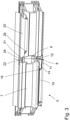
- the in 2 shown end of the profile 100 are inserted, in particular in such a way that the longitudinal end 110 engages in the notch 6, the notch 6 being formed complementary to the bevels 112, 114.
- the position and orientation of the profile 100 relative to the rod 5 are precisely defined.
- a suitably assembled state is in 4 to see. It can also be seen here that the cheeks 103 , 104 rest on the outer sides of the rod 5 in a complementary manner.
- a longitudinal extent of the profile 100 is transverse to the longitudinal extent of the bar 5, which corresponds to the typical design of a window frame.
- the respective cavities within the rollovers 10, 20, 130, 140 are closed by the other element, i.e. rod 5 or profile 100, in the area where rod 5 and profile 100 adjoin one another, so that air or moisture cannot penetrate is prevented.
- FIG. 5 shows rod parts 5a, 5b for a rod 5 for a process control according to a second embodiment.
- Overlaps 10, 130 or 20, 140 are not, but the overlays 10, 20 are only milled off in such a way that their end faces 11, 21 can directly adjoin end faces 131, 141 of the third and fourth overlays 130, 140.
- An intermediate region 9 is formed here, which is formed along the longitudinal extent of the rod 5 between the first flap 10 and the second flap 20, so that in contrast to the first exemplary embodiment the flaps 10, 20 do not directly adjoin one another with respect to the longitudinal direction.
- a first cheek 15 is formed immediately adjacent to the first flap 10 .
- a second cheek 25 is also formed immediately adjacent to the second flap 20 .
- These are seen in a transverse direction of the bar 5 overlapping with the respective flap 10, 20 or its outer side, so that the bevelling of the respective end face 11, 21 of the respective flap 10, 20 is not carried out in one work step with the formation of the notch 6 . Rather, the respective end face 11, 21 is formed using a separate tool, not shown, which is typically smaller, so that the respective cheek 15, 25 is retained.
- FIG. 6 shows a profile 100 for the second embodiment.
- the end faces 131, 141 of the third and fourth flaps 130, 140 are designed to be flat with the bevels 112, 114, as shown, so that processing in one work step is possible here.
- the planar design of the end faces 131, 141 corresponds to the fact that they should lie flat against the end faces 11, 21 of the first flap 10 and the second flap 20, which are also designed to be flat, as in figure 5 shown.
- FIG 7 shows an assembled state of the rod 5 of FIG figure 5 and the profile 100 from 6 . It can be seen that the rollovers 10, 130 and 20, 140 are not as in 4 overlap, but merely adjoin each other along respective connecting lines. In this way, a miter is produced which assumes an angle of 45° with respect to the longitudinal extensions of the bar 5 and the profile 100 .
- the third exemplary embodiment essentially corresponds to the first exemplary embodiment, with the first and second flaps 10, 20 being thinner in the third exemplary embodiment, viewed in the transverse direction of the rod 5, than in the first exemplary embodiment.
- a profile 100 for the procedure according to the third exemplary embodiment which is adapted to the rod 5 according to the third exemplary embodiment, but otherwise essentially corresponds in terms of its characteristics to the profile 100 according to the first exemplary embodiment.
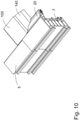
- FIG. 10 shows the bar 5 and the profile 100 in an assembled state according to the third embodiment in a perspective view.
- the second flap 20 and the fourth flap 140 partially overlap on the outside, a miter with an angle of 45° also being formed in this case.
- Respective cavities are closed by the respective other element.
Landscapes
- Engineering & Computer Science (AREA)
- Civil Engineering (AREA)
- Structural Engineering (AREA)
- Joining Of Corner Units Of Frames Or Wings (AREA)
- Special Wing (AREA)
Priority Applications (1)
| Application Number | Priority Date | Filing Date | Title |
|---|---|---|---|
| EP25159771.2A EP4534790A3 (fr) | 2020-06-22 | 2021-05-28 | Procédé de fixation d'un profilé à une barre, cadre de fenêtre et dispositif de fabrication d'un cadre de fenêtre ou cadre partiel de fenêtre |
Applications Claiming Priority (1)
| Application Number | Priority Date | Filing Date | Title |
|---|---|---|---|
| DE102020116441.6A DE102020116441A1 (de) | 2020-06-22 | 2020-06-22 | Verfahren zum Befestigen eines Profils an einem Stab, Fensterrahmen und Vorrichtung zur Herstellung eines Fensterrahmens oder Fensterteilrahmens |
Related Child Applications (2)
| Application Number | Title | Priority Date | Filing Date |
|---|---|---|---|
| EP25159771.2A Division EP4534790A3 (fr) | 2020-06-22 | 2021-05-28 | Procédé de fixation d'un profilé à une barre, cadre de fenêtre et dispositif de fabrication d'un cadre de fenêtre ou cadre partiel de fenêtre |
| EP25159771.2A Division-Into EP4534790A3 (fr) | 2020-06-22 | 2021-05-28 | Procédé de fixation d'un profilé à une barre, cadre de fenêtre et dispositif de fabrication d'un cadre de fenêtre ou cadre partiel de fenêtre |
Publications (3)
| Publication Number | Publication Date |
|---|---|
| EP3943703A1 true EP3943703A1 (fr) | 2022-01-26 |
| EP3943703B1 EP3943703B1 (fr) | 2025-09-24 |
| EP3943703C0 EP3943703C0 (fr) | 2025-09-24 |
Family
ID=76181017
Family Applications (2)
| Application Number | Title | Priority Date | Filing Date |
|---|---|---|---|
| EP21176654.8A Active EP3943703B1 (fr) | 2020-06-22 | 2021-05-28 | Procédé de fixation d'un profilé sur une barre, cadre de fenêtre et dispositif de fabrication d'un cadre de fenêtre ou d'une partie de cadre de fenêtre |
| EP25159771.2A Pending EP4534790A3 (fr) | 2020-06-22 | 2021-05-28 | Procédé de fixation d'un profilé à une barre, cadre de fenêtre et dispositif de fabrication d'un cadre de fenêtre ou cadre partiel de fenêtre |
Family Applications After (1)
| Application Number | Title | Priority Date | Filing Date |
|---|---|---|---|
| EP25159771.2A Pending EP4534790A3 (fr) | 2020-06-22 | 2021-05-28 | Procédé de fixation d'un profilé à une barre, cadre de fenêtre et dispositif de fabrication d'un cadre de fenêtre ou cadre partiel de fenêtre |
Country Status (4)
| Country | Link |
|---|---|
| EP (2) | EP3943703B1 (fr) |
| DE (1) | DE102020116441A1 (fr) |
| ES (1) | ES3054299T3 (fr) |
| PL (1) | PL3943703T3 (fr) |
Cited By (1)
| Publication number | Priority date | Publication date | Assignee | Title |
|---|---|---|---|---|
| DE102024123524A1 (de) * | 2024-08-19 | 2026-02-19 | Urban Gesellschaft mit beschränkter Haftung & Co. Maschinenbau Kommanditgesellschaft | Rahmen mit Kämpfer und Verfahren |
Citations (9)
| Publication number | Priority date | Publication date | Assignee | Title |
|---|---|---|---|---|
| GB2120714A (en) * | 1982-05-21 | 1983-12-07 | Lb | Window frame member |
| GB2196041A (en) * | 1986-09-23 | 1988-04-20 | Smith W H & Sons | Window frames |
| GB2288422A (en) * | 1994-04-06 | 1995-10-18 | Regency International Plc | Joining a transom to a mullion of a frame |
| GB2289080A (en) * | 1994-04-06 | 1995-11-08 | Regency International Plc | Joining frame members |
| EP0921259A1 (fr) * | 1997-12-02 | 1999-06-09 | Ht Troplast Ag | Fenêtre à la française à deux vantaux |
| GB2376657A (en) * | 2001-06-21 | 2002-12-24 | Gti Kombimatec Machines Ltd | Window profile notching tool |
| DE20206377U1 (de) * | 2002-04-23 | 2003-05-28 | Wilhelm Hollinger Maschinenbau GmbH, 66953 Pirmasens | Vorrichtung zum Verbinden eines Querholms mit Rahmenteilen eines Fensterrahmens, Türrahmens o.dgl. |
| EP2105282A2 (fr) * | 2008-03-25 | 2009-09-30 | ROTOX Besitz- und Verwaltungsgesellschaft mbH | Dispositif et procédé de liaison d'éléments de profilés d'un cadre de fenêtre ou de porte |
| GB2529717A (en) * | 2014-09-01 | 2016-03-02 | Everest Ltd | Improvements relating to window frame construction and method of assembly |
Family Cites Families (2)
| Publication number | Priority date | Publication date | Assignee | Title |
|---|---|---|---|---|
| GB9204226D0 (en) * | 1992-02-27 | 1992-04-08 | Bkl Extrusions Ltd | Window or door frame structure |
| GB2316117A (en) * | 1996-07-30 | 1998-02-18 | Cestrum Ltd | PVC window frames |
-
2020
- 2020-06-22 DE DE102020116441.6A patent/DE102020116441A1/de active Pending
-
2021
- 2021-05-28 EP EP21176654.8A patent/EP3943703B1/fr active Active
- 2021-05-28 ES ES21176654T patent/ES3054299T3/es active Active
- 2021-05-28 EP EP25159771.2A patent/EP4534790A3/fr active Pending
- 2021-05-28 PL PL21176654.8T patent/PL3943703T3/pl unknown
Patent Citations (9)
| Publication number | Priority date | Publication date | Assignee | Title |
|---|---|---|---|---|
| GB2120714A (en) * | 1982-05-21 | 1983-12-07 | Lb | Window frame member |
| GB2196041A (en) * | 1986-09-23 | 1988-04-20 | Smith W H & Sons | Window frames |
| GB2288422A (en) * | 1994-04-06 | 1995-10-18 | Regency International Plc | Joining a transom to a mullion of a frame |
| GB2289080A (en) * | 1994-04-06 | 1995-11-08 | Regency International Plc | Joining frame members |
| EP0921259A1 (fr) * | 1997-12-02 | 1999-06-09 | Ht Troplast Ag | Fenêtre à la française à deux vantaux |
| GB2376657A (en) * | 2001-06-21 | 2002-12-24 | Gti Kombimatec Machines Ltd | Window profile notching tool |
| DE20206377U1 (de) * | 2002-04-23 | 2003-05-28 | Wilhelm Hollinger Maschinenbau GmbH, 66953 Pirmasens | Vorrichtung zum Verbinden eines Querholms mit Rahmenteilen eines Fensterrahmens, Türrahmens o.dgl. |
| EP2105282A2 (fr) * | 2008-03-25 | 2009-09-30 | ROTOX Besitz- und Verwaltungsgesellschaft mbH | Dispositif et procédé de liaison d'éléments de profilés d'un cadre de fenêtre ou de porte |
| GB2529717A (en) * | 2014-09-01 | 2016-03-02 | Everest Ltd | Improvements relating to window frame construction and method of assembly |
Cited By (2)
| Publication number | Priority date | Publication date | Assignee | Title |
|---|---|---|---|---|
| DE102024123524A1 (de) * | 2024-08-19 | 2026-02-19 | Urban Gesellschaft mit beschränkter Haftung & Co. Maschinenbau Kommanditgesellschaft | Rahmen mit Kämpfer und Verfahren |
| EP4700203A1 (fr) | 2024-08-19 | 2026-02-25 | Urban GmbH & Co. KG | Cadre à double battant avec renfort inversé et procédé |
Also Published As
| Publication number | Publication date |
|---|---|
| DE102020116441A1 (de) | 2021-12-23 |
| EP4534790A2 (fr) | 2025-04-09 |
| EP4534790A3 (fr) | 2025-05-14 |
| PL3943703T3 (pl) | 2026-02-23 |
| ES3054299T3 (en) | 2026-02-02 |
| EP3943703B1 (fr) | 2025-09-24 |
| EP3943703C0 (fr) | 2025-09-24 |
Similar Documents
| Publication | Publication Date | Title |
|---|---|---|
| AT18487U1 (de) | Verbesserte Inpektionsklapptür | |
| DE10118791A1 (de) | Verbindungselement | |
| DE2740742A1 (de) | Leitungsverbindungselement und verfahren zu seiner herstellung | |
| DE3236719A1 (de) | Klemmverbinder fuer profilleisten | |
| DE2502634B2 (de) | Eckverbindung zweier auf gehrung geschnittener hohlprofile | |
| EP1587396B1 (fr) | Procede de production d'un corps de meuble | |
| EP1947283B1 (fr) | Vantail de porte ou de fenêtre et procédé destiné à sa fabrication | |
| EP3943703A1 (fr) | Procédé de fixation d'un profilé sur un barre, cadre de fenêtre et dispositif de fabrication d'un cadre de fenêtre ou d'une partie de cadre de fenêtre | |
| DE19539862C2 (de) | Eckverbindung für Hohlprofilstäbe zur Bildung von Rahmenteilen | |
| DE2912020C2 (de) | Verfahren zur Herstellung eines Rahmens | |
| DE3346067C2 (fr) | ||
| EP0371237B1 (fr) | Jeu de pièces détachées pour un châssis de porte | |
| DE3313402A1 (de) | Kupplung zur verbindung von aneinanderstossenden staeben in gitter- und/oder gestellstrukturen | |
| DE4121922C2 (de) | Reduzierfitting | |
| EP3670806A1 (fr) | Procédé de fixation d'un profilé sur une tige | |
| EP3540170B1 (fr) | Système de cadre de porte ou de fenêtre et procédé de fabrication | |
| DE202020102526U1 (de) | Mehrprofilpaneel | |
| DE10012762C1 (de) | Querverbinder | |
| DE10017514A1 (de) | Verfahren zur Herstellung einer Führungskette aus Kunststoff | |
| EP2418347A2 (fr) | Procédé de fabrication d'une liaison de profil en T | |
| EP1243212A2 (fr) | Cloison de douche | |
| EP3882424B1 (fr) | Agencement de penture | |
| EP4700203A1 (fr) | Cadre à double battant avec renfort inversé et procédé | |
| EP0117540B1 (fr) | Elément incurvé avec la longuer de l'arc prédéterminée faisant partie d'un système de montage constitué de tuyaux, de noeuds et d'élément incurvés | |
| EP1262622A2 (fr) | Elément de construction sous-jacent |
Legal Events
| Date | Code | Title | Description |
|---|---|---|---|
| PUAI | Public reference made under article 153(3) epc to a published international application that has entered the european phase |
Free format text: ORIGINAL CODE: 0009012 |
|
| STAA | Information on the status of an ep patent application or granted ep patent |
Free format text: STATUS: THE APPLICATION HAS BEEN PUBLISHED |
|
| AK | Designated contracting states |
Kind code of ref document: A1 Designated state(s): AL AT BE BG CH CY CZ DE DK EE ES FI FR GB GR HR HU IE IS IT LI LT LU LV MC MK MT NL NO PL PT RO RS SE SI SK SM TR |
|
| STAA | Information on the status of an ep patent application or granted ep patent |
Free format text: STATUS: REQUEST FOR EXAMINATION WAS MADE |
|
| 17P | Request for examination filed |
Effective date: 20220725 |
|
| RBV | Designated contracting states (corrected) |
Designated state(s): AL AT BE BG CH CY CZ DE DK EE ES FI FR GB GR HR HU IE IS IT LI LT LU LV MC MK MT NL NO PL PT RO RS SE SI SK SM TR |
|
| STAA | Information on the status of an ep patent application or granted ep patent |
Free format text: STATUS: EXAMINATION IS IN PROGRESS |
|
| 17Q | First examination report despatched |
Effective date: 20240617 |
|
| 17Q | First examination report despatched |
Effective date: 20240626 |
|
| GRAP | Despatch of communication of intention to grant a patent |
Free format text: ORIGINAL CODE: EPIDOSNIGR1 |
|
| STAA | Information on the status of an ep patent application or granted ep patent |
Free format text: STATUS: GRANT OF PATENT IS INTENDED |
|
| INTG | Intention to grant announced |
Effective date: 20250416 |
|
| GRAS | Grant fee paid |
Free format text: ORIGINAL CODE: EPIDOSNIGR3 |
|
| GRAA | (expected) grant |
Free format text: ORIGINAL CODE: 0009210 |
|
| STAA | Information on the status of an ep patent application or granted ep patent |
Free format text: STATUS: THE PATENT HAS BEEN GRANTED |
|
| AK | Designated contracting states |
Kind code of ref document: B1 Designated state(s): AL AT BE BG CH CY CZ DE DK EE ES FI FR GB GR HR HU IE IS IT LI LT LU LV MC MK MT NL NO PL PT RO RS SE SI SK SM TR |
|
| REG | Reference to a national code |
Ref country code: GB Ref legal event code: FG4D Free format text: NOT ENGLISH |
|
| REG | Reference to a national code |
Ref country code: CH Ref legal event code: EP |
|
| REG | Reference to a national code |
Ref country code: DE Ref legal event code: R096 Ref document number: 502021008767 Country of ref document: DE |
|
| REG | Reference to a national code |
Ref country code: IE Ref legal event code: FG4D Free format text: LANGUAGE OF EP DOCUMENT: GERMAN |
|
| U01 | Request for unitary effect filed |
Effective date: 20250926 |
|
| U07 | Unitary effect registered |
Designated state(s): AT BE BG DE DK EE FI FR IT LT LU LV MT NL PT RO SE SI Effective date: 20251008 |
|
| PG25 | Lapsed in a contracting state [announced via postgrant information from national office to epo] |
Ref country code: NO Free format text: LAPSE BECAUSE OF FAILURE TO SUBMIT A TRANSLATION OF THE DESCRIPTION OR TO PAY THE FEE WITHIN THE PRESCRIBED TIME-LIMIT Effective date: 20251224 |
|
| PG25 | Lapsed in a contracting state [announced via postgrant information from national office to epo] |
Ref country code: HR Free format text: LAPSE BECAUSE OF FAILURE TO SUBMIT A TRANSLATION OF THE DESCRIPTION OR TO PAY THE FEE WITHIN THE PRESCRIBED TIME-LIMIT Effective date: 20250924 |
|
| PG25 | Lapsed in a contracting state [announced via postgrant information from national office to epo] |
Ref country code: GR Free format text: LAPSE BECAUSE OF FAILURE TO SUBMIT A TRANSLATION OF THE DESCRIPTION OR TO PAY THE FEE WITHIN THE PRESCRIBED TIME-LIMIT Effective date: 20251225 |
|
| PG25 | Lapsed in a contracting state [announced via postgrant information from national office to epo] |
Ref country code: RS Free format text: LAPSE BECAUSE OF FAILURE TO SUBMIT A TRANSLATION OF THE DESCRIPTION OR TO PAY THE FEE WITHIN THE PRESCRIBED TIME-LIMIT Effective date: 20251224 |
|
| REG | Reference to a national code |
Ref country code: ES Ref legal event code: FG2A Ref document number: 3054299 Country of ref document: ES Kind code of ref document: T3 Effective date: 20260202 |
|
| PG25 | Lapsed in a contracting state [announced via postgrant information from national office to epo] |
Ref country code: SM Free format text: LAPSE BECAUSE OF FAILURE TO SUBMIT A TRANSLATION OF THE DESCRIPTION OR TO PAY THE FEE WITHIN THE PRESCRIBED TIME-LIMIT Effective date: 20250924 |
|
| PG25 | Lapsed in a contracting state [announced via postgrant information from national office to epo] |
Ref country code: IS Free format text: LAPSE BECAUSE OF FAILURE TO SUBMIT A TRANSLATION OF THE DESCRIPTION OR TO PAY THE FEE WITHIN THE PRESCRIBED TIME-LIMIT Effective date: 20260124 |
|
| PG25 | Lapsed in a contracting state [announced via postgrant information from national office to epo] |
Ref country code: SK Free format text: LAPSE BECAUSE OF FAILURE TO SUBMIT A TRANSLATION OF THE DESCRIPTION OR TO PAY THE FEE WITHIN THE PRESCRIBED TIME-LIMIT Effective date: 20250924 |