EP3945044A1 - Convoyeur continu au sol - Google Patents
Convoyeur continu au sol Download PDFInfo
- Publication number
- EP3945044A1 EP3945044A1 EP21188728.6A EP21188728A EP3945044A1 EP 3945044 A1 EP3945044 A1 EP 3945044A1 EP 21188728 A EP21188728 A EP 21188728A EP 3945044 A1 EP3945044 A1 EP 3945044A1
- Authority
- EP
- European Patent Office
- Prior art keywords
- piece goods
- floor
- designed
- continuous conveyor
- conveying
- Prior art date
- Legal status (The legal status is an assumption and is not a legal conclusion. Google has not performed a legal analysis and makes no representation as to the accuracy of the status listed.)
- Granted
Links
Images






Classifications
-
- B—PERFORMING OPERATIONS; TRANSPORTING
- B65—CONVEYING; PACKING; STORING; HANDLING THIN OR FILAMENTARY MATERIAL
- B65G—TRANSPORT OR STORAGE DEVICES, e.g. CONVEYORS FOR LOADING OR TIPPING, SHOP CONVEYOR SYSTEMS OR PNEUMATIC TUBE CONVEYORS
- B65G1/00—Storing articles, individually or in orderly arrangement, in warehouses or magazines
- B65G1/02—Storage devices
- B65G1/04—Storage devices mechanical
- B65G1/137—Storage devices mechanical with arrangements or automatic control means for selecting which articles are to be removed
- B65G1/1373—Storage devices mechanical with arrangements or automatic control means for selecting which articles are to be removed for fulfilling orders in warehouses
-
- B—PERFORMING OPERATIONS; TRANSPORTING
- B65—CONVEYING; PACKING; STORING; HANDLING THIN OR FILAMENTARY MATERIAL
- B65G—TRANSPORT OR STORAGE DEVICES, e.g. CONVEYORS FOR LOADING OR TIPPING, SHOP CONVEYOR SYSTEMS OR PNEUMATIC TUBE CONVEYORS
- B65G41/00—Supporting frames or bases for conveyors as a whole, e.g. transportable conveyor frames
- B65G41/001—Supporting frames or bases for conveyors as a whole, e.g. transportable conveyor frames with the conveyor adjustably mounted on the supporting frame or base
-
- B—PERFORMING OPERATIONS; TRANSPORTING
- B65—CONVEYING; PACKING; STORING; HANDLING THIN OR FILAMENTARY MATERIAL
- B65G—TRANSPORT OR STORAGE DEVICES, e.g. CONVEYORS FOR LOADING OR TIPPING, SHOP CONVEYOR SYSTEMS OR PNEUMATIC TUBE CONVEYORS
- B65G13/00—Roller-ways
- B65G13/11—Roller frames
-
- B—PERFORMING OPERATIONS; TRANSPORTING
- B65—CONVEYING; PACKING; STORING; HANDLING THIN OR FILAMENTARY MATERIAL
- B65G—TRANSPORT OR STORAGE DEVICES, e.g. CONVEYORS FOR LOADING OR TIPPING, SHOP CONVEYOR SYSTEMS OR PNEUMATIC TUBE CONVEYORS
- B65G13/00—Roller-ways
- B65G13/11—Roller frames
- B65G13/12—Roller frames adjustable
-
- B—PERFORMING OPERATIONS; TRANSPORTING
- B65—CONVEYING; PACKING; STORING; HANDLING THIN OR FILAMENTARY MATERIAL
- B65G—TRANSPORT OR STORAGE DEVICES, e.g. CONVEYORS FOR LOADING OR TIPPING, SHOP CONVEYOR SYSTEMS OR PNEUMATIC TUBE CONVEYORS
- B65G2203/00—Indexing code relating to control or detection of the articles or the load carriers during conveying
- B65G2203/02—Control or detection
- B65G2203/0208—Control or detection relating to the transported articles
- B65G2203/0233—Position of the article
-
- B—PERFORMING OPERATIONS; TRANSPORTING
- B65—CONVEYING; PACKING; STORING; HANDLING THIN OR FILAMENTARY MATERIAL
- B65G—TRANSPORT OR STORAGE DEVICES, e.g. CONVEYORS FOR LOADING OR TIPPING, SHOP CONVEYOR SYSTEMS OR PNEUMATIC TUBE CONVEYORS
- B65G65/00—Loading or unloading
-
- B—PERFORMING OPERATIONS; TRANSPORTING
- B65—CONVEYING; PACKING; STORING; HANDLING THIN OR FILAMENTARY MATERIAL
- B65G—TRANSPORT OR STORAGE DEVICES, e.g. CONVEYORS FOR LOADING OR TIPPING, SHOP CONVEYOR SYSTEMS OR PNEUMATIC TUBE CONVEYORS
- B65G65/00—Loading or unloading
- B65G65/23—Devices for tilting and emptying of containers
Definitions
- the invention relates to a floor-bound continuous conveyor for intralogistics, having at least one frame and at least one load handling device, which has a conveying plane for piece goods and which is designed to transport the piece goods in one conveying direction.
- the DE 10 2012 025 163 A1 describes a device for picking goods from source containers, consisting of a picking island, which is connected via a transport device to a warehouse having a large number of storage locations for storing and removing the source containers, the picking island consisting of at least one picking device with working on at least two levels Longitudinal conveyors exist, which promote the source containers to be picked to the work surface of a picker and remove them again after picking has taken place.
- a tilting conveyor which in turn has a further longitudinal conveyor which is pivotably mounted on a front structure in a horizontal pivot axis.
- the EP 3 003 918 A1 describes a storage and/or picking system in which there are several handling devices along the transport track between the transport track and the work station, and the handling devices each have a tray holder for at least one tray, with each tray holder from a horizontal loading position in which the tray holder is attached to the Transport path for the transfer of trays can be coupled, pivoted into a horizontally spaced from the loading position access position is arranged, wherein the pivoting movement is perpendicular to the conveying direction of the transport track, and the shelf holder is inclined in the access position pointing away from the loading position.
- the object of the invention is to create a floor-bound continuous conveyor in which piece goods transported on a load handling device can be offered to a user in an ergonomically advantageous manner, with the continuous conveyor having a simple and space-saving design.
- the object is achieved according to the invention by a floor-bound continuous conveyor with the features of claim 1 and by a system with the features of claim 16.
- One aspect relates to a floor-bound continuous conveyor for intralogistics, having at least one frame and at least one load handling device, which has a conveying level for piece goods and which is designed to transport the piece goods in one conveying direction, characterized by a stop means, which is designed to be on the conveying level to stop the packaged goods transported in the conveying direction at a predetermined position on the load-carrying means, and characterized by a movement device that is designed to move the packaged goods that are present at the stop means on the conveying plane from their starting position, which is on the conveying plane of the load-carrying means, to an end position that deviates from the starting position on the To move load handling equipment from the conveying level of the load handling equipment in the end position.
- the floor-bound continuous conveyor can have at least one roller conveyor, a belt conveyor, a chain conveyor, a vibrating conveyor and/or a chute, with the conveying plane being arranged at least essentially horizontally or inclined at an angle of up to about 15 degrees from the horizontal.
- the belt conveyor can be, for example, a belt conveyor, a segmented belt conveyor, a slat conveyor or a link belt conveyor.
- the invention is described below primarily using the example of a roller conveyor with a large number of rotatably mounted rollers. It is within the scope of the invention that, in all of the described embodiment variants, the named roller conveyor or the roller conveyor can be replaced by one of the other types of floor-bound continuous conveyors mentioned above.
- the load-carrying means can in particular also include an active load-carrying means, which has at least one (own) drive.
- one or more rollers can be assigned a drive or one or more rollers can have their own drive.
- the drive can be arranged in the roller body.
- Other examples of active load handling equipment are telescopic forks and belt conveyors.
- the load-carrying means can also be passive, for example as a gravity conveyor, in which the load is shifted following the force of gravity.
- a conveyor-type roller conveyor having at least one frame and a large number of rollers which are rotatably mounted on the frame and are arranged at a distance from one another and which form a conveying plane for piece goods, the conveying direction of which is at least essentially transverse to the axis of rotation of the rollers runs (i.e. around the X-axis, see e.g.
- a stop means which is designed to hold a piece of goods transported on the conveying level in the conveying direction at a predetermined position on the roller conveyor
- a movement device in particular a tilting device as a preferred movement device, which is designed to attach to the stop means on the conveying level to move or tip out or incline pending piece goods from its initial position on the conveying plane to an end position that deviates from the initial position from the conveying plane of the roller conveyor.
- the process of tipping or tilting is preferably started automatically as soon as the unit load makes mechanical contact with the stop means or reaches the stop position.
- At least one sensor can be provided to detect the position of the item on the stop means or the stop position, which sensor detects the presence of the item or the contact of the item with the stop means.
- a position sensor can be provided, which detects the positioning of the item in front of the stop means, in particular without having to detect mechanical contact between the stop means and the item.
- the at least one sensor can be connected to a controller of the continuous conveyor, so that the controller can automatically cause the item to be tilted or tilted by means of the movement device as soon as the item is in the intended position.
- a roller conveyor is understood to mean a conveyor system which, in terms of conveyor technology, represents a conveyor for conveying piece goods.
- the roller conveyor is therefore part of an internal transport system and belongs to the category of continuous conveyors.
- the roller conveyor is a stationary system and primarily serves to transport goods via an arrangement of rotatably mounted rollers. Roller conveyors can be used for sorting, distributing, storing and in particular picking piece goods.
- the general cargo can indeed be of any type.
- the piece goods can be packages, trays, containers, pallets, but also individual goods or workpieces.
- the invention is particularly expedient in connection with transport containers which are either designed to be open at the top or are closed, for example, by means of a lid, and which are set up to accommodate or temporarily store one or more other piece goods or goods.
- the piece goods conveyed on the roller conveyor can be a transport container or picking container in which specific other piece goods are stored and are delivered to a picking station, for example.
- Exactly one roller conveyor can preferably be provided, which transports the piece goods to a person at a picking station and also away from the person again. The supply and removal can be carried out using the same conveyor technology.
- a transport container or picking container should be provided in such a way that the person processing orders in the warehouse of a department store, for example, can remove the provided goods from the picking container in a particularly ergonomic manner.
- the piece goods are inclined or tilted at an angle of approximately 10 degrees to approximately 80 degrees, preferably at an angle of approximately 15 degrees to approximately 45 degrees.
- the frame forms a stationary substructure, which serves as a carrier and bearing for the rotatably mounted rollers.
- the frame can preferably be stationary, i.e. rigidly connected to a base.
- the frame can also be mobile, ie adjustable, for example pivotable in a substantially horizontal plane or adjustable in different inclines in a vertical direction, but is not mobile within the room due to the use of rollers instead of feet .
- floor-bound continuous conveyor means in particular that, as floor-bound conveyors, they are able to transport the goods to be transported horizontally, inclined and vertically.
- Floor-bound conveyors often require a lot of space on the floor and have a fixed transport route. They are also suitable as continuous conveyors for transporting large quantities of material or continuously required materials on defined routes, with loading and unloading preferably being able to take place at several points along the transport route. They are constantly, i.e. constantly or continuously, in motion, in contrast to the discontinuous conveyors, which move the transported goods in individual cycles.
- the rotatably mounted, spaced-apart rollers can either be actively driven or non-driven, ie freely rotating.
- the cargo is supported on the rollers during its transport on the roller conveyor, ie the cargo is, depending on its size, ie its base on a number of rollers.
- the piece goods can, for example in the case of non-driven rollers, move by the influence of gravity, in particular when the conveying plane is arranged inclined relative to the horizontal plane in the conveying direction.
- the rollers can be designed to be driven and thereby actively drive the piece goods in the conveying direction and thus move them forward.
- the conveying level is determined by the supporting contact lines on the lateral surfaces of the rollers on which the piece goods are supported with their bottom surface.
- the conveying plane generally extends essentially in the horizontal plane, unless the conveying plane is arranged inclined in the desired manner, for example to allow conveying by means of the influence of gravity.
- the conveying direction is determined by the alignment of the axes of rotation of the rollers and the direction of rotation of the rollers.
- the conveying direction generally runs along a straight path, but can also follow along a curved path.
- the conveying direction also generally lies in an at least substantially horizontal plane, but can also lie in an inclined plane.
- the conveying direction determines in which direction the transported piece goods are moved.
- the conveying direction is transverse to the axis of rotation of the rollers.
- the stop means can preferably be located in the area of a final section, ie at the end of a roller conveyor section.
- the roller conveyor can, for example, lead to a local picking station, the roller conveyor at the picking station ends.
- Such a roller conveyor generally serves to bring the goods held in a transport container, in particular a special type of goods or group of goods, which are transported from a storage area by the roller conveyor, to the picking station.
- the transport container brought in in each case accordingly forms a source container from which, for example, a person who, for example, processes purchase orders in the warehouse of a department store, removes a certain number of the goods provided and transfers them to a target container, for example, in which the mixed goods are put together according to the purchase order.
- the lifting gear does not necessarily have to be in the area of an end section, i.e. at the end of a roller conveyor section. Rather, the stop means can also be located in any desired section of the roller conveyor, in particular in the middle, if the respective logistical concept requires it.
- the stop means can be lowered so that the stop means no longer protrudes above the conveying plane, but is stored in a concealed manner. In such an arrangement, the piece goods can roll unhindered over the sling without being stopped.
- the stop means is not in the region of an end section, ie at the end of a roller conveyor section, but is located in any other section of the roller conveyor section, in particular in the middle.
- the piece goods, in particular the transport container can undergo a change in position about a tilting axis by means of the tilting device, which at least in Substantially transverse or perpendicular to its conveying direction.
- the piece goods, in particular the transport container can undergo a change in position about a tilting axis by means of the tilting device, which is at least substantially along or parallel to its conveying direction.
- the piece goods, in particular the transport container are therefore inclined sideways away from the roller conveyor.
- the predetermined position at which the piece goods, in particular the transport container, is stopped by the stop means and tipped there by means of the tipping device can therefore be in the region of a final section, i.e. at the end of a roller conveyor section, or in any other section of the roller conveyor section, in particular in the middle .
- the tipping device is designed to lift the piece goods, in particular the transport container, on one side while maintaining the position and position of the load-receiving means, for example rollers on the roller conveyor.
- the tipping device is designed, the general cargo, in particular to lift the transport container out of the plane of the roles of the roller conveyor, for example, tilting.
- the rollers of the roller conveyor remain unchanged in their previous positions during the tilting movement. To this extent, the conveying level is determined by the unchanged positions of the load handling devices, for example the rollers of the roller conveyor.
- the piece goods in particular the transport container, are tilted or pivoted or tilted from an initial position standing on the conveying plane into an end position that deviates from the initial position.
- the initial position corresponds to the conveying level of the continuous conveyor.
- the piece goods In the end position, the piece goods have tipped out of the conveying level of the continuous conveyor. Tilting or tipping out is understood to mean any type of change in the position of the item that is a rotation of the item about an at least substantially horizontal axis of rotation.
- the piece goods are preferably pivoted about an axis of rotation running in the conveying direction of the continuous conveyor (X-axis) or the piece goods are pivoted about a rotational axis running transversely, i.e. at right angles to the conveying direction of the continuous conveyor, and lying essentially in the conveying plane (Y axis).
- the axis of rotation can also be below the conveying plane.
- the axis of rotation can migrate, in particular during the pivoting.
- tipping or tipping out does not mean a rotation of the piece goods about a vertical axis of rotation.
- the tipping or tipping out can be a tipping, which can optionally be done by raising or lowering an edge, in particular a lower edge, of the item.
- One can further lower edge opposite this lower edge can also be raised or lowered in the opposite direction.
- the lower edge and the further lower edge can be the two opposite front edges and rear edges of the piece goods, or the respective lower right side edge and the lower left side edge.
- the respective piece goods which are also referred to as conveyed goods, can be, for example, a container, either with or without content, a picking container (source container, destination container), a small parts load carrier (KLT), a package, a tray, a workpiece carrier, a cardboard box, a tray, such as a cardboard carrier, a bundle, dimensionally stable and rigid bag goods and / or other conveyable piece goods, such as food.
- a container either with or without content
- a picking container source container, destination container
- KLT small parts load carrier
- a package a tray, a workpiece carrier, a cardboard box, a tray, such as a cardboard carrier, a bundle, dimensionally stable and rigid bag goods and / or other conveyable piece goods, such as food.
- the cargo stands with its base on the load handling device, in particular on a number of rollers corresponding to the size of the bottom surface of the cargo, ie the cargo stands, for example, on several rollers.
- the unit load is lifted off at least a number of rollers by means of the tilting device, without the rollers and/or the frame changing its position and location.
- the piece goods are supported, for example, only on a single roller and the sling.
- the piece goods can be brought into a correspondingly varied tipping angle.
- the piece goods can thus be tilted by means of the tilting device without the rollers and/or the frame of the continuous conveyor, for example, having to be changed in their respective positions and/or locations.
- the contact device can be constituted, for example, by a rigid bar or a rotatable roller which contacts the item on the ground in order to carry out the tipping of the item.
- the piece goods, in particular the transport container are not discharged from the roller conveyor, but remain above the conveying plane of the roller conveyor.
- the piece goods, in particular the transport container can then be easily moved back or tilted back onto the conveying plane of the roller conveyor using the movement device or tilting device according to the invention and transported further or transported back using the load handling device, in particular the roller conveyor.
- the movement device can be a tilting device, which can be arranged in particular in a stationary manner with respect to the frame of the roller conveyor and can have an adjustable contact device, which is designed to tilt the piece goods present on the stop means from its starting position to its end position, the contact device for this purpose being in a storage position is mounted adjustable in an operating position relative to the load handling means with respect to the frame.
- the storage position can be characterized in that the contact device cannot or does not make mechanical contact with the load picked up by the load handling device.
- the contacting, in particular a direct contact, of the load and the contact device preferably takes place only when the contact device is transferred from the storage position to the operating position. In the actuation position, in particular, direct mechanical contact is made between the load and the contact device. This means that the elements of the load handling device which support the load while the contact device is in the storage position are preferably different from the elements of the contact device.
- the tipping device can therefore be a handling device connected to the roller conveyor, which is designed to tip the piece goods from its initial position on the conveying plane of the roller conveyor into its final position.
- the adjustable contact device of the tilting device forms an end effector, which makes contact with the piece goods in order to reorient the piece goods.
- the contact device can, for example, lift a bottom of the item from below.
- the contact device can, for example, engage a lateral side wall of the item in a force-fitting or form-fitting manner and bring the item into the correspondingly desired storage, i.e. pivot it.
- the contact device is mounted on the frame so that it can be adjusted from a storage position to an operating position. Accordingly, the tilting device can have a drive or a motor, which moves and adjusts the contact device relative to the frame and thus relative to the conveying plane.
- the tilting device can be designed to tilt the piece goods lying against the stop means about a tilting axis aligned at least essentially transversely to the conveying direction, in particular along the axes of rotation of the rollers.
- the bottom section of the item facing away from the slinging device can be formed in particular by that bottom half which is so far away from the side of the slinging device with respect to the center of mass of the item, so that when the item is lifted by the contact device, the lifted item is thrown forward in the direction of the sling tilts and not in the opposite direction.
- the bottom of the unit load can be divided into the just described bottom section facing away from the slinging means and a bottom section facing the slinging means.
- the bottom section facing away and the bottom section facing can complement each other to form the entire bottom surface of the piece goods.
- the tilting device can be designed to tilt the piece goods that are present on the stop means about a tilting axis that is aligned at least essentially along the conveying direction, in particular transversely to the axes of rotation of the rollers.
- the tipping device can have at least one contact device mounted on the frame in a height-adjustable manner, which is designed to lower at least sections of a bottom section of the piece goods facing the stop means in order to tilt the piece goods into their end position.
- the tilting device can have at least one pivoting means pivotably mounted on the frame, such as a pivoting arm, which has the contact device at its distal pivoting center end, in particular one pivoting arm end of the pivoting arm.
- the distal Pivoting center end can engage in a form-fitting and/or force-fitting manner on the item to be dumped or pivoted.
- the at least one pivoting arm which is pivotably mounted on the frame, can have the contact device on its distal end of the pivoting arm.
- the contact device can have, for example, in the form of a pin projecting laterally in the direction of the piece goods.
- the laterally projecting peg in particular two pegs acting on the piece goods on opposite lateral sides, positively engages in one or more corresponding receptacles which are connected to the piece goods or the transport container.
- the receptacles on the piece goods can, for example, be designed in one piece with the lateral side walls of the piece goods, i.e. the transport container.
- the pin of the contact device can in this respect form a holding element which is designed to cooperate in a form-fitting manner during the tilting of the item with a receptacle designed as a recess on a lateral side wall of the item.
- the contact device can have a holding member which is designed to interact in a form-fitting manner with a projection or a recess on a lateral side wall of the item during the tipping of the item.
- the drive or motor can be formed by a drum motor or a driven roller or drive roller.
- drum motors also known as Driven rollers are used, for example, in conveyor roller conveyors, are used as motors to actuate the tilting device.
- driven rollers the axis of the drum motor is fixed with respect to the frame and the shell wall of the drum motor, which forms the roller, rotates.
- Different types of pinions for traction drives can be fixed to the outer surface of the drum motor and also driven identically to the outer surface.
- the contact means is connected to the traction means and is therefore also driven by the drum motor. By using the traction means, the rotational movement of the drum motor is converted into an essentially linear movement of the contact means.
- a combination of racks and pinions can also be used, or pneumatic cylinders or hydraulic cylinders, which perform a linear movement.
- powered telescopes can also be used.
- the drive can be formed by a motor with a reduction gear.
- This motor can also be a drum motor.
- an additional transmission stage can be implemented, in that the countershaft motor has a separate drive pinion, for example, which drives an output via a second traction mechanism, which drives the first traction mechanism.
- a belt pulley can also be provided, for example.
- first traction device and/or the second traction device can optionally be designed as a chain, a toothed belt, a V-belt or a flat belt.
- the contact device can be formed by a rotatably mounted contact roller which, in its storage position, is positioned between two adjacent rollers of the roller conveyor below the conveying plane of the rollers or in the conveying plane of the rollers.
- the rotatable contact roller can be replaced by a fixed rod, in particular a circular cylinder rod.
- the fixed rod can be equipped, in particular coated, with a friction-reducing sliding material, for example.
- the bottom of the piece goods can roll on a rotatably mounted contact roller, depending on the surface condition of the bottom of the piece goods and/or the outer surface of a fixed rod, in particular a circular cylinder rod, sliding of the Bottom of the cargo on the lateral surface of the fixed, ie non-rotating rod, in particular the circular cylinder rod should be sufficient and appropriate.
- the tipping device can have at least one contact device which is mounted on the frame in a height-adjustable manner and can be adjusted in particular by the traction means, which is designed to lift a bottom section of the unit load facing away from the stop means from below in order to tilt the unit load into its end position, in particular by means of a left-hand movement means and a right-hand one Movement means, wherein the left-hand movement means and the right-hand movement means are coupled to each other below the conveying plane.
- the left-hand means of movement is on the on a lateral side of the article and the right-hand moving means is arranged on a lateral side of the article opposite to the left-hand moving means.
- the movement means on the left and the movement means on the right do not encompass the piece goods from above.
- the contact device can be mounted on a traction device of the tilting device in a revolving or reversing manner so that it can be adjusted in height, with the traction device being mounted on the frame and driven by a (drum) motor.
- the traction means can optionally be in the form of a chain, a toothed belt, a V-belt, a flat belt or a cable.
- the traction mechanism carries the contact device, for example on two opposite end sections of the contact device.
- the contact means can be a rotatable or fixed roller, a rod or at least a web-like edge.
- the contact device is raised or lowered by the at least one traction means rotating continuously or reversing.
- stops can be provided which mechanically or electronically stop the contact device in the respective storage position or operating position, or sensors can be provided which detect the current ( Can detect height) position of the contact device.
- a control device can be connected to the sensors, which control device controls the drive device of the tilting device as a function of the position of the contact device detected by the sensors, in order to To bring contact device automatically in the currently desired position (storage position or operating position).
- mechanical, electromechanical or electronic stops can be provided in particular, which, depending on the direction of rotation of the traction mechanism, allow the contact device to strike either a lower stop associated with the storage position or an upper stop associated with the actuating position.
- the tipping device can have at least one contact device mounted on the frame such that it can be adjusted in height, in particular adjustable by the traction means, and which is designed to lower a bottom section of the piece goods facing the stop means in order to bring the piece goods into their end position or tilt them.
- the contact device can be formed by a fixed rod, in particular a circular cylinder rod or a rotatably mounted contact roller which is positioned in its storage position, in particular between two adjacent rollers of the roller conveyor, below the conveying plane or in the conveying plane.
- the contact device can be formed by a support plate which has at least one cutout for one of the rollers of the roller conveyor, the support plate being designed to lift and pivot a bottom section of the item from below in order to bring the item into its end position or tilt it .
- the support plate can be designed in such a way that the piece goods, in particular the transport container, are not only gripped in places or at specific points, but are lifted flat on its base and moved along the desired path for tipping.
- the piece goods, in particular the transport container does not necessarily have to be rotated about a fixed tilting axis, but can perform a different, different tilting movement along any desired movement path.
- the support plate can have cutouts so that each cutout can be penetrated by a single roll, so that in the storage position of the support plate the piece goods stand up exclusively on the rolls and are no longer in contact with the support plate as such. Accordingly, the piece goods, in particular the transport container, when the carrying plate is in its storage position, can be moved unhindered over the carrying plate in the conveying direction if the stop means is also removed from the conveying direction.
- the floor-bound continuous conveyor can accordingly be designed as at least one roller conveyor and have a large number of rollers which are rotatably mounted on the frame and are arranged spaced apart from one another as load handling means, which form the conveying plane for the piece goods, the conveying direction of which runs at least essentially transversely to the axis of rotation of the rollers, wherein the stop means is designed to hold a piece of goods transported on the conveying plane in the conveying direction at a predetermined position on the rollers, and the tilting device is designed to rest against the stop means on the conveying plane Tipping out general cargo from its initial position standing on the conveying level into an end position deviating from the initial position from the conveying level of the load-carrying means.
- the tilting device can be stationary with respect to the frame of the roller conveyor and the contact device can be movably mounted with respect to the frame from a storage position into an operating position relative to the rollers of the roller conveyor.
- the tilting device can be designed in such a way that the piece goods lying against the stop means are tilted about a tilting axis which is aligned at least essentially longitudinally or transversely to the axes of rotation of the rollers.
- the contact device can be formed by a support plate which has at least one closed-edged or open-edged cutout for one of the rollers of the roller conveyor, the support plate being designed to lift and pivot a bottom section of the item from below in order to tip the item into its end position.
- the goods to be conveyed are conveyed via a stationary conveying device that runs essentially horizontally to a target position, for example in the picking area.
- This support is based on the goods to person principle.
- the conveyed goods for example a transport container an adjustment of the position, ie the orientation of the conveyed material is required.
- the rear edge of the goods to be conveyed i.e. on a side facing away from the picking area, is lifted by an essentially vertical proportion with the aid of an end effector, which is moved by means of a lifting device, i.e. the goods to be conveyed are inclined, with the pivot point or the axis of rotation of the goods being conveyed preferably shifting at its lower edge and at a maximum distance of half the length of the conveyed item from its front edge, ie the side facing the picking area.
- the front top edge of the item to be conveyed changes its position towards the picking area and downwards, as a result of which access to the item to be conveyed is facilitated and the ergonomics of the picking process is increased.
- the lifting device consists essentially of two traction drives that are mechanically coupled to one another and that can be driven either directly via a common drive or via a separate intermediate gear.
- the at least one traction drive or the two traction drives move an end effector that is designed to change the position of the conveyed item, in particular to incline or tilt the conveyed item.
- the at least one traction mechanism required for the stroke can have a drive wheel, a deflection wheel, the traction mechanism itself and an end effector or another part for accommodating it.
- the end effector can be fixed in the run of the traction means, for example by means of a tensioning element.
- the power can be introduced and the two drives coupled by a central drum motor, which is equipped with drive wheels on both sides.
- the mechanical coupling of the two drives can be done according to the same principle, but here a non-driven roller is used. This is also equipped with another wheel, which is driven by a drive motor via a countershaft.
- the end effector can perform a substantially vertical translatory (lifting) movement and, in particular, can be positioned steplessly.
- the end effector is mounted in a guided manner to absorb forces acting transversely to the direction of movement of the traction mechanism.
- a lifting and/or lowering movement of the end effector can be carried out either by a complete rotation of the traction mechanism with the direction of movement/rotation remaining the same or by a reversal of direction with the direction of movement being alternately reversed. If the latter is the case, the end positions of the end effector can be selected using mechanical stops in such a way that mechanical self-locking of the end effector is ensured. Without end stops, the torque required for locking must be generated over the entire period of use by the drive or an additional holding brake on the drive.
- the end effector represents part of the conveying plane in its lower end position, over which the conveyed goods can be moved, i.e. transported and made available.
- the end effector is constantly in contact with the conveyed goods.
- the goods to be conveyed can be lowered back into their horizontal orientation and removed via the same conveyor device that was used to supply them.
- An active change in the position of a conveyed item on a conveying element can be achieved by the conveying-technical roller conveyor according to the invention.
- the conveying roller conveyor according to the invention can serve to provide the conveyed goods in a defined position on a conveying element.
- the invention can ensure an ergonomic provision of conveyed goods for picking.
- a cost-effective design can be achieved by using standard components. In this respect, only a very small amount of project-specific adaptation is necessary.
- the outer shape of the device can be open on the ceiling side, so that the height of the conveyed goods is not restricted and consequently collisions with the surrounding infrastructure can also be avoided.
- the device according to the invention thus serves to actively change the position of a conveyed item on a stationary conveying device that runs essentially horizontally.
- a change in position of the item to be conveyed can take place either by raising its rear edge (essentially vertical) and/or by lowering its front edge (essentially vertical).
- An advantageous drive unit can, for example, be driven directly as a traction drive, i.e. driven without a countershaft, as a traction drive via a countershaft, or be designed as a driven cable pull.
- a stepless design for individual position changes due to a change in lifting height can be advantageous.
- a version with two end positions is also possible.
- a displacement of the tilting axis of the piece good preferably takes place during a displacement of the piece good from the starting position to the end position.
- This can preferably take place in that the point of contact between the contact device and the piece good, at which the mechanical contact between the contact device and the piece good takes place, is variable during the displacement.
- the contact device can roll or slip relative to the supported bottom of the piece goods. This can be caused by the movement of the contact device relative to the frame of the load handling device.
- the piece goods can shift due to gravity due to the lifting and tilting of gravity.
- it is possible for the piece goods during the tipping to shift with its side proximal to the attachment means into an empty space or a gap, which extends in particular between the attachment means and the load-carrying means.
- the empty space or the gap can exist statically, i.e. independently of the presence of the piece goods, or it can exist transiently, i.e. only for a limited time, for example only during tipping, in particular by actuating one or more elements of the load handling device.
- the piece goods are not supported in some areas within the conveying level between the lifting gear and the lifting device.
- the piece goods are supported in certain areas between the sling and the load handling device in the initial position within the conveying plane, for example by one or more rollers and/or a plate and/or a belt as the preferred load handling device.
- the support for the piece goods can be shifted below the conveying level, for example by shifting the load handling device, in particular the at least one roller, and/or the plate and/or the belt, downwards or to the side at least in certain areas, so that the empty space is created into which the piece goods can move.
- This shifting of the load handling device, in particular the at least one roller, and/or the plate and/or the belt can take place actively or passively.
- a drive With active displacement, a drive is provided which enables displacement so that, advantageously, a void can be predetermined at a predetermined time.
- the drive of the contact device can preferably also serve as a drive for the active displacement.
- no drive is provided, which advantageously enables a simpler construction of the continuous conveyor.
- one or more rollers and/or plate(s) and/or belt(s) can be resiliently mounted. During the tipping of the piece goods, the rollers can be shifted downwards or below the conveying plane or pressed, in particular by the weight of the cargo.
- the empty space is created by tilting the item itself.
- the empty space or the gap can be designed to correspond to approximately 10% to approximately 40%, preferably approximately 20% to approximately 30%, of the extent of the piece goods in the conveying direction.
- the empty space or the gap can be about 10 cm to about 40 cm, preferably about 15 cm to about 30 cm long in the conveying direction.
- the center of gravity in the end position preferably remains essentially at the height of the center of gravity in the starting position.
- the center of gravity of the item in the end position is particularly preferably below the center of gravity in the starting position.
- a combination of tipping by the tipping device and lowering the piece goods into an empty space between the slinging means and the load-carrying means means that the opening inclines towards a user and the user thus has improved access to the piece goods and also has the necessary space in the vertical is reduced.
- the conveyance to and from the first and/or second continuous conveyor can take place via the same conveyor technology.
- the second continuous conveyor can in particular be aligned essentially horizontally and in particular have a roller conveyor.
- the second continuous conveyor preferably protrudes towards the user in relation to the first continuous conveyor, preferably by more than approximately 5 cm, particularly preferably by more than approximately 10 cm and in particular by more than approximately 15 cm.
- this gives the user better access to the piece goods served on the second, lower continuous conveyor.
- the conveying roller conveyor 1a shown as a specific example of a floor-bound continuous conveyor 1 according to the invention has at least one frame 2 and a plurality of rotatably mounted on the frame 2, juxtaposed spaced rollers 3 on.
- the rollers 3 form a conveying plane E for piece goods 4.
- the conveying direction F of the rollers 3 runs at least essentially transversely to the axis of rotation D of the rollers 3.
- the piece goods 4 are designed as transport containers, in which other piece goods or goods or objects can be transported grouped by type, for example.
- the conveyor-technical roller conveyor 1a has a stop means 5, which is designed to stop an item 4 transported on the conveyor plane E in the conveying direction F at a predetermined position on the roller conveyor 1a.
- the stop means 5 can, as in 1 is shown, are formed by a fixed or rotatably mounted stop roller 5a.
- the stop means 5 or the stop roller 5a can be emphasized from the conveying plane E in order, as in 1 is shown to have the stop action.
- the conveyor-technical roller conveyor 1a also has a movement device 6, which in the case of the present exemplary embodiment is designed in the special embodiment as a tilting device 6a, which is designed to move the piece goods 4 that are pending on the stop means 5 on the conveying plane E from their position on the conveying plane E standing starting position AL ( 1 ) to an end position EL ( 2 ) to tilt out of the conveying plane E of the roller conveyor 1a.
- a movement device 6 which in the case of the present exemplary embodiment is designed in the special embodiment as a tilting device 6a, which is designed to move the piece goods 4 that are pending on the stop means 5 on the conveying plane E from their position on the conveying plane E standing starting position AL ( 1 ) to an end position EL ( 2 ) to tilt out of the conveying plane E of the roller conveyor 1a.
- the item 4 stands with its bottom wall on a number of rollers 3 corresponding to the size of the bottom area of the item 4 , ie the item 4 stands flat on the several rollers 3 .
- the piece goods 4 are lifted off at least several rollers 3 by means of the tilting device 6a without the rollers 3 and/or the frame 2 changing their position and location.
- the piece goods 4 are supported only on a single roller of the rollers 3 and on the stop means 5 or the stop roller 5a.
- the piece goods 4 can be brought into a correspondingly varied tilting angle.
- the piece goods 4 can be tilted by means of the tilting device 6a without the rollers 3 and/or the frame 2 of the conveyor-technical roller conveyor 1a having to be changed in their respective positions and/or layers.
- the tilting device 6a is arranged stationary with respect to the frame 2 of the roller conveyor 1a.
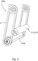
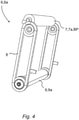
- the tilting device 6a has, as in particular in 3 and 4 is shown, an adjustable contact device 7, which is designed to tilt the item 4 present on the stop means 5 from its starting position AL into its end position EL, the contact device 7 for this purpose moving from a storage position VP ( 3 ) to an actuation position BP ( 4 ) is adjustable with respect to the frame 2.
- the contact device 7 In the storage position VP, the contact device 7 is at least essentially in the conveying plane E, ie the contact device 7 is at least approximately at the level of the rollers 3 or does not protrude beyond the rollers 3 upwards. This is particularly in 1 evident.
- the tilting device 6a is designed to rotate the piece goods 4 that are present on the stop means 5 by an at least essentially longitudinal to the axes of rotation D ( 1 ) of the roles 3 aligned tilting axis K ( 1 ) to tilt.
- the tilting direction of the piece goods 4 runs in the conveying direction of the conveying roller conveyor 1a.
- the tilting device 6a according to the embodiments according to FIG Fig.1 to Fig.7 has at least one height-adjustably mounted contact device 7 on the frame 2, which is designed to lift a bottom section BA1 of the item 4 facing away from the stop means 5 from below in order to tip the item 4 into its end position EL.
- the bottom section BA1 of the item 4 facing away from the lifting device 5 is formed by that bottom half which is so far away from the side of the lifting device 5 with respect to the center of mass of the item 4 so that when the item 4 is lifted by the contact device 7 the lifted Cargo 4 tilts forward in the direction of the sling 5 and not in the opposite direction.
- the bottom of the piece goods 4 can be divided into the just described bottom section BA1 facing away from the stop means 5 and a bottom section BA2 facing the stop means 5 .
- the bottom section BA1 and the bottom section BA2 can complement each other to the entire bottom surface of the piece goods 4 ( Fig.2 ).
- the tipping device 6a can have at least one contact device 7, which is mounted on the frame 2 in a height-adjustable manner and is designed to lower, at least in sections, a bottom section BA2 of the unit load 4 that faces the stop means 5, in order to tip the unit load 4 into its end position EL, as is the case in particular in figure 5 is illustrated.
- figure 5 shows that during the tipping, the piece goods move with their side (BA2) proximal to the slinging means into an empty space (21) or a gap, which extends in particular between the slinging means 5 and load handling means 3.
- the piece goods advantageously sink vertically downwards in their position.
- Such an at least partial lowering of the floor section BA2 is already in to a small extent 2 shown.
- Such a lowering of the floor section BA2 is particularly clear in the embodiment variant according to FIG 9 shown.
- the piece goods 4 do not pivot around their lower front corner 4a, as is the case, for example, in 8 is shown, but about an instantaneous center MP, which lies within the volume of the piece goods 4, as is shown in 9 is shown.
- the front lower corner 4a dips below the conveying plane E, so that the bottom section BA2 of the unit load 4 facing the stop means 5 is lowered at least in sections.
- the stop means 5 or the stop roller 5a can also be formed by one of the rollers 3.
- One or more of the rollers 3 is preferably designed to be displaceable relative to the other rollers 3 .
- the roller closest to the stop means 5 is shown in its starting position again after a displacement and supports a side wall of the piece goods 4.
- the particularly linear displacement can preferably take place in a direction essentially perpendicular to the conveying plane E.
- one or more of the rollers 3 can be arranged to be displaceable, in particular by means of an associated drive.
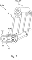
- the contact device 7 can be mounted on a first traction device 8 of the tilting device 6a in a rotating or reversing manner so that it can be adjusted in height, with the traction device 8 being mounted on the frame 2 and being driven by a motor 9 .
- the motor 9 is formed by a drum motor 9a.
- drum motors which are also used as driven rollers 3 of the conveyor-type roller conveyor 1a, can be used as the motor 9 for actuating the tilting device 6a.
- driven rollers 3 the axis of the drum motor 9a is fixed with respect to the frame 2 and the shell wall of the drum motor 9a, which forms the roller 3, rotates.
- the motor 9 is formed by a countershaft motor 9b.
- an additional transmission stage 10 can be implemented, in which the shaft of the countershaft motor 9b has a separate drive pinion 11, which drives an output 13 via a second traction mechanism 12, which drives the first traction mechanism 8.
- a belt pulley (not shown) can also be provided, for example.
- first traction device 8 and/or the second traction device 12 can optionally be designed as a chain, a toothed belt, a V-belt or a flat belt. Accordingly, the in Figures 1 to 7 Replace the drive pinion 11 shown and other gears with suitable pulleys.
- the contact device 7 can, as in Fig.1 to Fig.7 is formed by a rotatably mounted contact roller 7a which, in its storage position VP, is positioned between two adjacent rollers 3 of the roller conveyor 1a below the conveying plane E of the rollers 3 or in the conveying plane E of the rollers 3, as is the case in particular in 1 is evident.
- the Fig.1 to Fig.5 The rotatable contact roller 7a shown can be replaced by a fixed rod, in particular a circular cylinder rod 7b, as is the case, for example, in 8 and 9 is indicated.
- the bottom of the piece goods 4 can roll on a rotatably mounted contact roller 7a during a tipping process, depending on the surface condition of the bottom of the piece goods 4 and/or the outer surface of a fixed rod, in particular a circular cylinder rod 7b , a sliding of the bottom of the piece goods 4 on the lateral surface of the fixed, ie non-rotating rod or the circular cylinder rod 7b may be sufficient and expedient.
- the tilting device 6a can have at least one pivoting means 14 ( 10 ) in particular a swivel arm 14a ( 11 ) have, which has at its distal end of the pivoting arm the contact device 7, for example in the form of a pin 7c projecting laterally in the direction of the item 4.
- the laterally projecting pin 7c in particular two on opposite lateral sides, engages in one or more corresponding receptacles 15 on the item 4, which are connected to the item 4, in a form-fitting manner.
- the receptacles 15 on the item 4 can, for example, be formed in one piece with the lateral side walls of the item 4 .
- the pin 7c of the contact device 7 can in this respect form a holding member which is designed to interact positively with a receptacle 15 designed as a recess on a lateral side wall of the item 4 during the tilting of the item 4 .
- the contact device 7 can be formed by a first support device 7d, which has, for example, a plurality of cutouts 16 or a plurality of strip-like or comb-like elevations 17 as a preferred contour element 17, one of which in each case projects movably between two rollers 3 of the roller conveyor 1a, as is the case in particular in 12 and 15 can be seen, with the carrying device 7d or its strip-like or comb-like elevations being designed to lift and pivot a bottom section of the item 4 from below in order to tilt the item 4 into its end position EL, as is shown in 12 is illustrated.
- the 13 shows the support device 7d in a plan view on its own with five contour elements 17 between which four cutouts 16 are arranged, with one roller 3 being able to be assigned to one of the cutouts 16 in each case.
- the support device 7d is designed for pivoting about a pivot axis S running parallel to the axes of rotation of the rollers 3 .
- the 15 shows the support device 7d in a schematic perspective representation with its four strip-like or comb-like elevations.
- the contact device 7 can be formed by a comb-like second support device 7e, which, for example, has a plurality of parallel-aligned, spaced apart spaced, ridges 17 as preferred contour elements 17.
- the comb-like carrying device 7e is designed for pivoting about a pivot axis S running at right angles to the axes of rotation of the rollers 3, as is also shown in FIG 13 is shown. In 13 it is shown that the pivot axis S is oriented substantially orthogonally to the pivot axis S.
- the figure 16 shows a system 30 with a first floor-bound continuous conveyor 32 according to the invention and a second continuous conveyor 34 arranged below the first ascending conveyor 32.
- the frame 2 with the load-carrying means 3 of the first continuous conveyor is inclined by about 9 degrees relative to the horizontal towards the user.
- the piece goods 4 are tilted towards the user by about 35 degrees relative to the horizontal in this embodiment.
- the second continuous conveyor is oriented horizontally and the piece goods 4 are not tilted.
- the user nevertheless has access to the piece goods, since the second continuous conveyor is arranged below the first continuous conveyor 32 in such a way that the second continuous conveyor 32 or the piece goods 4 served on it towards the user opposite the first continuous conveyor 32 or the piece goods 4 served on it by a distance d.
- This board d is sufficiently dimensioned that the user can grab at least one item from the item 4 and place it in the item 4 .
Landscapes
- Engineering & Computer Science (AREA)
- Mechanical Engineering (AREA)
- Attitude Control For Articles On Conveyors (AREA)
- Rollers For Roller Conveyors For Transfer (AREA)
Applications Claiming Priority (1)
| Application Number | Priority Date | Filing Date | Title |
|---|---|---|---|
| PCT/EP2020/071739 WO2022022839A1 (fr) | 2020-07-31 | 2020-07-31 | Transporteur continu installé au sol |
Publications (2)
| Publication Number | Publication Date |
|---|---|
| EP3945044A1 true EP3945044A1 (fr) | 2022-02-02 |
| EP3945044B1 EP3945044B1 (fr) | 2023-12-27 |
Family
ID=71950614
Family Applications (1)
| Application Number | Title | Priority Date | Filing Date |
|---|---|---|---|
| EP21188728.6A Active EP3945044B1 (fr) | 2020-07-31 | 2021-07-30 | Convoyeur continu au sol |
Country Status (3)
| Country | Link |
|---|---|
| US (1) | US11787640B2 (fr) |
| EP (1) | EP3945044B1 (fr) |
| WO (1) | WO2022022839A1 (fr) |
Cited By (2)
| Publication number | Priority date | Publication date | Assignee | Title |
|---|---|---|---|---|
| CN116873528A (zh) * | 2023-06-15 | 2023-10-13 | 刘风 | 一种物流用物流分选装置 |
| US20240417163A1 (en) * | 2023-06-16 | 2024-12-19 | Impact Automation, Inc. | Sliding tilt loader |
Families Citing this family (2)
| Publication number | Priority date | Publication date | Assignee | Title |
|---|---|---|---|---|
| FR3150800B1 (fr) * | 2023-07-05 | 2025-09-05 | Fives Xcella | Systeme de preparation de commandes |
| CN118811407B (zh) * | 2024-09-20 | 2024-11-22 | 江苏国越储能科技有限公司 | 一种储能集装箱电池层架工装流水线 |
Citations (10)
| Publication number | Priority date | Publication date | Assignee | Title |
|---|---|---|---|---|
| US2344664A (en) * | 1941-02-11 | 1944-03-21 | Calavo Growers Of California | Box dumping apparatus |
| JPH0434226U (fr) * | 1990-07-16 | 1992-03-23 | ||
| JPH0797020A (ja) * | 1993-09-29 | 1995-04-11 | Kanebo Ltd | 作業台付きコンベア |
| JPH0723713U (ja) * | 1993-09-28 | 1995-05-02 | 矢崎化工株式会社 | 重力式流動棚装置 |
| KR100764984B1 (ko) * | 2006-07-18 | 2007-10-09 | 기아자동차주식회사 | 부품 경사 공급장치 |
| US7766151B2 (en) * | 2004-01-07 | 2010-08-03 | Ssi Schaefer Peem Gmbh | Picking station |
| DE212010000076U1 (de) * | 2009-05-28 | 2012-02-09 | Tgw Mechanics Gmbh | Kommissioniereinrichtung |
| DE102012025163A1 (de) | 2012-12-21 | 2014-06-26 | Servus Intralogistics Gmbh | Verfahren und Vorrichtung zur Kommissionierung von Gütern |
| DE202015008475U1 (de) * | 2015-12-10 | 2016-02-15 | Rls Robotics Logistics Solutions Gmbh | Vorrichtung zum Drehen bzw. Orientieren von Stückgütern auf einer Stetigförderanlage |
| EP3003918A1 (fr) | 2013-05-31 | 2016-04-13 | Kardex Produktion Deutschland GmbH | Dispositif pivotant de manutention de bacs d'un système de stockage et/ou de préparation de commandes |
Family Cites Families (2)
| Publication number | Priority date | Publication date | Assignee | Title |
|---|---|---|---|---|
| DE3141514C1 (de) * | 1981-10-20 | 1983-07-21 | Gebhardt Fördertechnik GmbH, 6920 Sinsheim | Vorrichtung zum Entleeren von mit uebereinander liegendem Stueckgut beladenen Behaeltern |
| US6098783A (en) * | 1997-06-25 | 2000-08-08 | Neos, Inc. | Transfer machine tipper mechanism |
-
2020
- 2020-07-31 WO PCT/EP2020/071739 patent/WO2022022839A1/fr not_active Ceased
-
2021
- 2021-07-30 US US17/389,481 patent/US11787640B2/en active Active
- 2021-07-30 EP EP21188728.6A patent/EP3945044B1/fr active Active
Patent Citations (10)
| Publication number | Priority date | Publication date | Assignee | Title |
|---|---|---|---|---|
| US2344664A (en) * | 1941-02-11 | 1944-03-21 | Calavo Growers Of California | Box dumping apparatus |
| JPH0434226U (fr) * | 1990-07-16 | 1992-03-23 | ||
| JPH0723713U (ja) * | 1993-09-28 | 1995-05-02 | 矢崎化工株式会社 | 重力式流動棚装置 |
| JPH0797020A (ja) * | 1993-09-29 | 1995-04-11 | Kanebo Ltd | 作業台付きコンベア |
| US7766151B2 (en) * | 2004-01-07 | 2010-08-03 | Ssi Schaefer Peem Gmbh | Picking station |
| KR100764984B1 (ko) * | 2006-07-18 | 2007-10-09 | 기아자동차주식회사 | 부품 경사 공급장치 |
| DE212010000076U1 (de) * | 2009-05-28 | 2012-02-09 | Tgw Mechanics Gmbh | Kommissioniereinrichtung |
| DE102012025163A1 (de) | 2012-12-21 | 2014-06-26 | Servus Intralogistics Gmbh | Verfahren und Vorrichtung zur Kommissionierung von Gütern |
| EP3003918A1 (fr) | 2013-05-31 | 2016-04-13 | Kardex Produktion Deutschland GmbH | Dispositif pivotant de manutention de bacs d'un système de stockage et/ou de préparation de commandes |
| DE202015008475U1 (de) * | 2015-12-10 | 2016-02-15 | Rls Robotics Logistics Solutions Gmbh | Vorrichtung zum Drehen bzw. Orientieren von Stückgütern auf einer Stetigförderanlage |
Cited By (3)
| Publication number | Priority date | Publication date | Assignee | Title |
|---|---|---|---|---|
| CN116873528A (zh) * | 2023-06-15 | 2023-10-13 | 刘风 | 一种物流用物流分选装置 |
| US20240417163A1 (en) * | 2023-06-16 | 2024-12-19 | Impact Automation, Inc. | Sliding tilt loader |
| US12497235B2 (en) * | 2023-06-16 | 2025-12-16 | Impact Automation, Inc. | Sliding tilt loader |
Also Published As
| Publication number | Publication date |
|---|---|
| WO2022022839A1 (fr) | 2022-02-03 |
| EP3945044B1 (fr) | 2023-12-27 |
| US20220033189A1 (en) | 2022-02-03 |
| US11787640B2 (en) | 2023-10-17 |
Similar Documents
| Publication | Publication Date | Title |
|---|---|---|
| EP3945044B1 (fr) | Convoyeur continu au sol | |
| EP2655222B1 (fr) | Poste de manutention de tablettes et procédé pour le chargement et le déchargement manuel de tablettes | |
| EP4144673B1 (fr) | Dispositif de transfert permettant de décharger une aide au chargement pour le transport, station de déchargement et entrepôt de préparation des commandes permettant de stocker et de préparer des commandes des marchandises | |
| EP2032472B1 (fr) | Station de remplissage intégrée à un rayonnage et procédé de préparation de commande | |
| EP2315714B1 (fr) | Dispositif entièrement automatique de préparation d'articles dans des contenants de commandes | |
| EP2019799B1 (fr) | Station de remplissage séparée | |
| EP2098464B1 (fr) | Dispositif de commissionnement et procédé de commissionnement | |
| EP2539248A1 (fr) | Dispositif de suspension de charge pour un appareil de commande pour rayonnages, appareil de commande pour rayonnages et système de stockage | |
| EP3330200A1 (fr) | Procédé de stockage et de distribution d'objets ainsi que système de stockage permettant la mise en uvre dudit procédé | |
| DE102013015456A1 (de) | System und Verfahren zum gemeinsamen Kommissionieren von zerbrechlichen und unzerbrechlichen Artikeln | |
| DE202004021388U1 (de) | Kommissionierplatz | |
| EP2611718A1 (fr) | Convoyeur de positionnement, système de stockage et procédé de reprise de charges isolées sur un convoyeur | |
| EP3550979A1 (fr) | Dispositif de stockage, de cuisson et de distribution de produits de boulangerie-pâtisserie | |
| EP1432627B1 (fr) | Dispositif de preparation des commandes | |
| CH718440B1 (de) | Übergabestation für Packroboter. | |
| AT522732A1 (de) | Vertikaler umsetzer für eine fördereinrichtung | |
| EP2450298B2 (fr) | Procédé et dispositif manuel pour déposer des articles sur un support de charge | |
| WO2024256203A1 (fr) | Élévateur d'entrepôt à chargement et déchargement automatiques fournis par un véhicule | |
| EP3251987B1 (fr) | Systeme de chargement pour marchandises au detail comprenant un dispositif de chargement transportable | |
| EP4282794A1 (fr) | Dispositif et procédé d'empilement | |
| DE3343732C2 (fr) | ||
| EP3334284A1 (fr) | Dispositif de transport et de distribution de produits alimentaires | |
| EP4613674A1 (fr) | Dispositif et procédé pour charger et décharger des unités de transport d'un système de transport suspendu | |
| WO1986003178A1 (fr) | Dispositif pour le stockage d'articles plats | |
| DE2263330A1 (de) | Speicheranordnung |
Legal Events
| Date | Code | Title | Description |
|---|---|---|---|
| PUAI | Public reference made under article 153(3) epc to a published international application that has entered the european phase |
Free format text: ORIGINAL CODE: 0009012 |
|
| STAA | Information on the status of an ep patent application or granted ep patent |
Free format text: STATUS: THE APPLICATION HAS BEEN PUBLISHED |
|
| AK | Designated contracting states |
Kind code of ref document: A1 Designated state(s): AL AT BE BG CH CY CZ DE DK EE ES FI FR GB GR HR HU IE IS IT LI LT LU LV MC MK MT NL NO PL PT RO RS SE SI SK SM TR |
|
| STAA | Information on the status of an ep patent application or granted ep patent |
Free format text: STATUS: REQUEST FOR EXAMINATION WAS MADE |
|
| 17P | Request for examination filed |
Effective date: 20220726 |
|
| RBV | Designated contracting states (corrected) |
Designated state(s): AL AT BE BG CH CY CZ DE DK EE ES FI FR GB GR HR HU IE IS IT LI LT LU LV MC MK MT NL NO PL PT RO RS SE SI SK SM TR |
|
| P01 | Opt-out of the competence of the unified patent court (upc) registered |
Effective date: 20230528 |
|
| RIC1 | Information provided on ipc code assigned before grant |
Ipc: B65G 13/12 20060101ALI20230616BHEP Ipc: B65G 1/137 20060101AFI20230616BHEP |
|
| GRAP | Despatch of communication of intention to grant a patent |
Free format text: ORIGINAL CODE: EPIDOSNIGR1 |
|
| STAA | Information on the status of an ep patent application or granted ep patent |
Free format text: STATUS: GRANT OF PATENT IS INTENDED |
|
| INTG | Intention to grant announced |
Effective date: 20230731 |
|
| GRAS | Grant fee paid |
Free format text: ORIGINAL CODE: EPIDOSNIGR3 |
|
| GRAA | (expected) grant |
Free format text: ORIGINAL CODE: 0009210 |
|
| STAA | Information on the status of an ep patent application or granted ep patent |
Free format text: STATUS: THE PATENT HAS BEEN GRANTED |
|
| AK | Designated contracting states |
Kind code of ref document: B1 Designated state(s): AL AT BE BG CH CY CZ DE DK EE ES FI FR GB GR HR HU IE IS IT LI LT LU LV MC MK MT NL NO PL PT RO RS SE SI SK SM TR |
|
| REG | Reference to a national code |
Ref country code: GB Ref legal event code: FG4D Free format text: NOT ENGLISH |
|
| REG | Reference to a national code |
Ref country code: CH Ref legal event code: EP |
|
| REG | Reference to a national code |
Ref country code: DE Ref legal event code: R096 Ref document number: 502021002269 Country of ref document: DE |
|
| REG | Reference to a national code |
Ref country code: IE Ref legal event code: FG4D Free format text: LANGUAGE OF EP DOCUMENT: GERMAN |
|
| PG25 | Lapsed in a contracting state [announced via postgrant information from national office to epo] |
Ref country code: GR Free format text: LAPSE BECAUSE OF FAILURE TO SUBMIT A TRANSLATION OF THE DESCRIPTION OR TO PAY THE FEE WITHIN THE PRESCRIBED TIME-LIMIT Effective date: 20240328 |
|
| REG | Reference to a national code |
Ref country code: LT Ref legal event code: MG9D |
|
| PG25 | Lapsed in a contracting state [announced via postgrant information from national office to epo] |
Ref country code: LT Free format text: LAPSE BECAUSE OF FAILURE TO SUBMIT A TRANSLATION OF THE DESCRIPTION OR TO PAY THE FEE WITHIN THE PRESCRIBED TIME-LIMIT Effective date: 20231227 |
|
| PG25 | Lapsed in a contracting state [announced via postgrant information from national office to epo] |
Ref country code: ES Free format text: LAPSE BECAUSE OF FAILURE TO SUBMIT A TRANSLATION OF THE DESCRIPTION OR TO PAY THE FEE WITHIN THE PRESCRIBED TIME-LIMIT Effective date: 20231227 |
|
| PG25 | Lapsed in a contracting state [announced via postgrant information from national office to epo] |
Ref country code: LT Free format text: LAPSE BECAUSE OF FAILURE TO SUBMIT A TRANSLATION OF THE DESCRIPTION OR TO PAY THE FEE WITHIN THE PRESCRIBED TIME-LIMIT Effective date: 20231227 Ref country code: GR Free format text: LAPSE BECAUSE OF FAILURE TO SUBMIT A TRANSLATION OF THE DESCRIPTION OR TO PAY THE FEE WITHIN THE PRESCRIBED TIME-LIMIT Effective date: 20240328 Ref country code: FI Free format text: LAPSE BECAUSE OF FAILURE TO SUBMIT A TRANSLATION OF THE DESCRIPTION OR TO PAY THE FEE WITHIN THE PRESCRIBED TIME-LIMIT Effective date: 20231227 Ref country code: ES Free format text: LAPSE BECAUSE OF FAILURE TO SUBMIT A TRANSLATION OF THE DESCRIPTION OR TO PAY THE FEE WITHIN THE PRESCRIBED TIME-LIMIT Effective date: 20231227 Ref country code: BG Free format text: LAPSE BECAUSE OF FAILURE TO SUBMIT A TRANSLATION OF THE DESCRIPTION OR TO PAY THE FEE WITHIN THE PRESCRIBED TIME-LIMIT Effective date: 20240327 |
|
| REG | Reference to a national code |
Ref country code: NL Ref legal event code: MP Effective date: 20231227 |
|
| PG25 | Lapsed in a contracting state [announced via postgrant information from national office to epo] |
Ref country code: NL Free format text: LAPSE BECAUSE OF FAILURE TO SUBMIT A TRANSLATION OF THE DESCRIPTION OR TO PAY THE FEE WITHIN THE PRESCRIBED TIME-LIMIT Effective date: 20231227 |
|
| PG25 | Lapsed in a contracting state [announced via postgrant information from national office to epo] |
Ref country code: SE Free format text: LAPSE BECAUSE OF FAILURE TO SUBMIT A TRANSLATION OF THE DESCRIPTION OR TO PAY THE FEE WITHIN THE PRESCRIBED TIME-LIMIT Effective date: 20231227 Ref country code: RS Free format text: LAPSE BECAUSE OF FAILURE TO SUBMIT A TRANSLATION OF THE DESCRIPTION OR TO PAY THE FEE WITHIN THE PRESCRIBED TIME-LIMIT Effective date: 20231227 Ref country code: NO Free format text: LAPSE BECAUSE OF FAILURE TO SUBMIT A TRANSLATION OF THE DESCRIPTION OR TO PAY THE FEE WITHIN THE PRESCRIBED TIME-LIMIT Effective date: 20240327 Ref country code: NL Free format text: LAPSE BECAUSE OF FAILURE TO SUBMIT A TRANSLATION OF THE DESCRIPTION OR TO PAY THE FEE WITHIN THE PRESCRIBED TIME-LIMIT Effective date: 20231227 Ref country code: LV Free format text: LAPSE BECAUSE OF FAILURE TO SUBMIT A TRANSLATION OF THE DESCRIPTION OR TO PAY THE FEE WITHIN THE PRESCRIBED TIME-LIMIT Effective date: 20231227 Ref country code: HR Free format text: LAPSE BECAUSE OF FAILURE TO SUBMIT A TRANSLATION OF THE DESCRIPTION OR TO PAY THE FEE WITHIN THE PRESCRIBED TIME-LIMIT Effective date: 20231227 |
|
| PG25 | Lapsed in a contracting state [announced via postgrant information from national office to epo] |
Ref country code: IS Free format text: LAPSE BECAUSE OF FAILURE TO SUBMIT A TRANSLATION OF THE DESCRIPTION OR TO PAY THE FEE WITHIN THE PRESCRIBED TIME-LIMIT Effective date: 20240427 |
|
| PG25 | Lapsed in a contracting state [announced via postgrant information from national office to epo] |
Ref country code: CZ Free format text: LAPSE BECAUSE OF FAILURE TO SUBMIT A TRANSLATION OF THE DESCRIPTION OR TO PAY THE FEE WITHIN THE PRESCRIBED TIME-LIMIT Effective date: 20231227 |
|
| PG25 | Lapsed in a contracting state [announced via postgrant information from national office to epo] |
Ref country code: SK Free format text: LAPSE BECAUSE OF FAILURE TO SUBMIT A TRANSLATION OF THE DESCRIPTION OR TO PAY THE FEE WITHIN THE PRESCRIBED TIME-LIMIT Effective date: 20231227 |
|
| PG25 | Lapsed in a contracting state [announced via postgrant information from national office to epo] |
Ref country code: SM Free format text: LAPSE BECAUSE OF FAILURE TO SUBMIT A TRANSLATION OF THE DESCRIPTION OR TO PAY THE FEE WITHIN THE PRESCRIBED TIME-LIMIT Effective date: 20231227 Ref country code: SK Free format text: LAPSE BECAUSE OF FAILURE TO SUBMIT A TRANSLATION OF THE DESCRIPTION OR TO PAY THE FEE WITHIN THE PRESCRIBED TIME-LIMIT Effective date: 20231227 Ref country code: RO Free format text: LAPSE BECAUSE OF FAILURE TO SUBMIT A TRANSLATION OF THE DESCRIPTION OR TO PAY THE FEE WITHIN THE PRESCRIBED TIME-LIMIT Effective date: 20231227 Ref country code: IT Free format text: LAPSE BECAUSE OF FAILURE TO SUBMIT A TRANSLATION OF THE DESCRIPTION OR TO PAY THE FEE WITHIN THE PRESCRIBED TIME-LIMIT Effective date: 20231227 Ref country code: IS Free format text: LAPSE BECAUSE OF FAILURE TO SUBMIT A TRANSLATION OF THE DESCRIPTION OR TO PAY THE FEE WITHIN THE PRESCRIBED TIME-LIMIT Effective date: 20240427 Ref country code: EE Free format text: LAPSE BECAUSE OF FAILURE TO SUBMIT A TRANSLATION OF THE DESCRIPTION OR TO PAY THE FEE WITHIN THE PRESCRIBED TIME-LIMIT Effective date: 20231227 Ref country code: CZ Free format text: LAPSE BECAUSE OF FAILURE TO SUBMIT A TRANSLATION OF THE DESCRIPTION OR TO PAY THE FEE WITHIN THE PRESCRIBED TIME-LIMIT Effective date: 20231227 |
|
| PG25 | Lapsed in a contracting state [announced via postgrant information from national office to epo] |
Ref country code: PL Free format text: LAPSE BECAUSE OF FAILURE TO SUBMIT A TRANSLATION OF THE DESCRIPTION OR TO PAY THE FEE WITHIN THE PRESCRIBED TIME-LIMIT Effective date: 20231227 Ref country code: PT Free format text: LAPSE BECAUSE OF FAILURE TO SUBMIT A TRANSLATION OF THE DESCRIPTION OR TO PAY THE FEE WITHIN THE PRESCRIBED TIME-LIMIT Effective date: 20240429 |
|
| PG25 | Lapsed in a contracting state [announced via postgrant information from national office to epo] |
Ref country code: PT Free format text: LAPSE BECAUSE OF FAILURE TO SUBMIT A TRANSLATION OF THE DESCRIPTION OR TO PAY THE FEE WITHIN THE PRESCRIBED TIME-LIMIT Effective date: 20240429 Ref country code: PL Free format text: LAPSE BECAUSE OF FAILURE TO SUBMIT A TRANSLATION OF THE DESCRIPTION OR TO PAY THE FEE WITHIN THE PRESCRIBED TIME-LIMIT Effective date: 20231227 |
|
| REG | Reference to a national code |
Ref country code: DE Ref legal event code: R097 Ref document number: 502021002269 Country of ref document: DE |
|
| PG25 | Lapsed in a contracting state [announced via postgrant information from national office to epo] |
Ref country code: DK Free format text: LAPSE BECAUSE OF FAILURE TO SUBMIT A TRANSLATION OF THE DESCRIPTION OR TO PAY THE FEE WITHIN THE PRESCRIBED TIME-LIMIT Effective date: 20231227 |
|
| PG25 | Lapsed in a contracting state [announced via postgrant information from national office to epo] |
Ref country code: DK Free format text: LAPSE BECAUSE OF FAILURE TO SUBMIT A TRANSLATION OF THE DESCRIPTION OR TO PAY THE FEE WITHIN THE PRESCRIBED TIME-LIMIT Effective date: 20231227 |
|
| PLBE | No opposition filed within time limit |
Free format text: ORIGINAL CODE: 0009261 |
|
| STAA | Information on the status of an ep patent application or granted ep patent |
Free format text: STATUS: NO OPPOSITION FILED WITHIN TIME LIMIT |
|
| 26N | No opposition filed |
Effective date: 20240930 |
|
| PG25 | Lapsed in a contracting state [announced via postgrant information from national office to epo] |
Ref country code: MC Free format text: LAPSE BECAUSE OF FAILURE TO SUBMIT A TRANSLATION OF THE DESCRIPTION OR TO PAY THE FEE WITHIN THE PRESCRIBED TIME-LIMIT Effective date: 20231227 |
|
| REG | Reference to a national code |
Ref country code: CH Ref legal event code: PL |
|
| PG25 | Lapsed in a contracting state [announced via postgrant information from national office to epo] |
Ref country code: LU Free format text: LAPSE BECAUSE OF NON-PAYMENT OF DUE FEES Effective date: 20240730 |
|
| PG25 | Lapsed in a contracting state [announced via postgrant information from national office to epo] |
Ref country code: LU Free format text: LAPSE BECAUSE OF NON-PAYMENT OF DUE FEES Effective date: 20240730 |
|
| PG25 | Lapsed in a contracting state [announced via postgrant information from national office to epo] |
Ref country code: SI Free format text: LAPSE BECAUSE OF FAILURE TO SUBMIT A TRANSLATION OF THE DESCRIPTION OR TO PAY THE FEE WITHIN THE PRESCRIBED TIME-LIMIT Effective date: 20231227 Ref country code: BE Free format text: LAPSE BECAUSE OF NON-PAYMENT OF DUE FEES Effective date: 20240731 Ref country code: CH Free format text: LAPSE BECAUSE OF NON-PAYMENT OF DUE FEES Effective date: 20240731 |
|
| REG | Reference to a national code |
Ref country code: BE Ref legal event code: MM Effective date: 20240731 |
|
| PGFP | Annual fee paid to national office [announced via postgrant information from national office to epo] |
Ref country code: GB Payment date: 20250605 Year of fee payment: 5 |
|
| PGFP | Annual fee paid to national office [announced via postgrant information from national office to epo] |
Ref country code: FR Payment date: 20250610 Year of fee payment: 5 |
|
| PG25 | Lapsed in a contracting state [announced via postgrant information from national office to epo] |
Ref country code: IE Free format text: LAPSE BECAUSE OF NON-PAYMENT OF DUE FEES Effective date: 20240730 |
|
| PGFP | Annual fee paid to national office [announced via postgrant information from national office to epo] |
Ref country code: DE Payment date: 20250604 Year of fee payment: 5 |
|
| PGFP | Annual fee paid to national office [announced via postgrant information from national office to epo] |
Ref country code: AT Payment date: 20251020 Year of fee payment: 5 |
|
| PG25 | Lapsed in a contracting state [announced via postgrant information from national office to epo] |
Ref country code: CY Free format text: LAPSE BECAUSE OF FAILURE TO SUBMIT A TRANSLATION OF THE DESCRIPTION OR TO PAY THE FEE WITHIN THE PRESCRIBED TIME-LIMIT; INVALID AB INITIO Effective date: 20210730 |
|
| PG25 | Lapsed in a contracting state [announced via postgrant information from national office to epo] |
Ref country code: HU Free format text: LAPSE BECAUSE OF FAILURE TO SUBMIT A TRANSLATION OF THE DESCRIPTION OR TO PAY THE FEE WITHIN THE PRESCRIBED TIME-LIMIT; INVALID AB INITIO Effective date: 20210730 |