EP3945657A1 - Intelligente batteriezelle mit integrierter überwachung und schaltern - Google Patents
Intelligente batteriezelle mit integrierter überwachung und schaltern Download PDFInfo
- Publication number
- EP3945657A1 EP3945657A1 EP21188834.2A EP21188834A EP3945657A1 EP 3945657 A1 EP3945657 A1 EP 3945657A1 EP 21188834 A EP21188834 A EP 21188834A EP 3945657 A1 EP3945657 A1 EP 3945657A1
- Authority
- EP
- European Patent Office
- Prior art keywords
- battery cell
- battery pack
- devices
- battery
- switches
- Prior art date
- Legal status (The legal status is an assumption and is not a legal conclusion. Google has not performed a legal analysis and makes no representation as to the accuracy of the status listed.)
- Pending
Links
Images











Classifications
-
- H—ELECTRICITY
- H01—ELECTRIC ELEMENTS
- H01M—PROCESSES OR MEANS, e.g. BATTERIES, FOR THE DIRECT CONVERSION OF CHEMICAL ENERGY INTO ELECTRICAL ENERGY
- H01M10/00—Secondary cells; Manufacture thereof
- H01M10/42—Methods or arrangements for servicing or maintenance of secondary cells or secondary half-cells
- H01M10/425—Structural combination with electronic components, e.g. electronic circuits integrated to the outside of the casing
- H01M10/4257—Smart batteries, e.g. electronic circuits inside the housing of the cells or batteries
-
- H—ELECTRICITY
- H02—GENERATION; CONVERSION OR DISTRIBUTION OF ELECTRIC POWER
- H02J—ELECTRIC POWER NETWORKS; CIRCUIT ARRANGEMENTS OR SYSTEMS FOR SUPPLYING OR DISTRIBUTING ELECTRIC POWER; SYSTEMS FOR STORING ELECTRIC ENERGY
- H02J7/00—Circuit arrangements for charging or discharging batteries or for supplying loads from batteries
- H02J7/80—Circuit arrangements for charging or discharging batteries or for supplying loads from batteries including monitoring or indicating arrangements
-
- H—ELECTRICITY
- H01—ELECTRIC ELEMENTS
- H01M—PROCESSES OR MEANS, e.g. BATTERIES, FOR THE DIRECT CONVERSION OF CHEMICAL ENERGY INTO ELECTRICAL ENERGY
- H01M10/00—Secondary cells; Manufacture thereof
- H01M10/42—Methods or arrangements for servicing or maintenance of secondary cells or secondary half-cells
- H01M10/48—Accumulators combined with arrangements for measuring, testing or indicating the condition of cells, e.g. the level or density of the electrolyte
- H01M10/482—Accumulators combined with arrangements for measuring, testing or indicating the condition of cells, e.g. the level or density of the electrolyte for several batteries or cells simultaneously or sequentially
-
- H—ELECTRICITY
- H02—GENERATION; CONVERSION OR DISTRIBUTION OF ELECTRIC POWER
- H02J—ELECTRIC POWER NETWORKS; CIRCUIT ARRANGEMENTS OR SYSTEMS FOR SUPPLYING OR DISTRIBUTING ELECTRIC POWER; SYSTEMS FOR STORING ELECTRIC ENERGY
- H02J7/00—Circuit arrangements for charging or discharging batteries or for supplying loads from batteries
- H02J7/50—Circuit arrangements for charging or discharging batteries or for supplying loads from batteries acting upon multiple batteries simultaneously or sequentially
- H02J7/52—Circuit arrangements for charging or discharging batteries or for supplying loads from batteries acting upon multiple batteries simultaneously or sequentially for charge balancing, e.g. equalisation of charge between batteries
-
- H—ELECTRICITY
- H02—GENERATION; CONVERSION OR DISTRIBUTION OF ELECTRIC POWER
- H02J—ELECTRIC POWER NETWORKS; CIRCUIT ARRANGEMENTS OR SYSTEMS FOR SUPPLYING OR DISTRIBUTING ELECTRIC POWER; SYSTEMS FOR STORING ELECTRIC ENERGY
- H02J7/00—Circuit arrangements for charging or discharging batteries or for supplying loads from batteries
- H02J7/90—Regulation of charging or discharging current or voltage
- H02J7/94—Regulation of charging or discharging current or voltage in response to battery current
-
- H—ELECTRICITY
- H02—GENERATION; CONVERSION OR DISTRIBUTION OF ELECTRIC POWER
- H02J—ELECTRIC POWER NETWORKS; CIRCUIT ARRANGEMENTS OR SYSTEMS FOR SUPPLYING OR DISTRIBUTING ELECTRIC POWER; SYSTEMS FOR STORING ELECTRIC ENERGY
- H02J7/00—Circuit arrangements for charging or discharging batteries or for supplying loads from batteries
- H02J7/90—Regulation of charging or discharging current or voltage
- H02J7/96—Regulation of charging or discharging current or voltage in response to battery voltage
-
- H—ELECTRICITY
- H02—GENERATION; CONVERSION OR DISTRIBUTION OF ELECTRIC POWER
- H02J—ELECTRIC POWER NETWORKS; CIRCUIT ARRANGEMENTS OR SYSTEMS FOR SUPPLYING OR DISTRIBUTING ELECTRIC POWER; SYSTEMS FOR STORING ELECTRIC ENERGY
- H02J7/00—Circuit arrangements for charging or discharging batteries or for supplying loads from batteries
- H02J7/90—Regulation of charging or discharging current or voltage
- H02J7/971—Regulation of charging or discharging current or voltage the charge cycle being controlled or terminated in response to non-electric parameters
-
- H—ELECTRICITY
- H02—GENERATION; CONVERSION OR DISTRIBUTION OF ELECTRIC POWER
- H02J—ELECTRIC POWER NETWORKS; CIRCUIT ARRANGEMENTS OR SYSTEMS FOR SUPPLYING OR DISTRIBUTING ELECTRIC POWER; SYSTEMS FOR STORING ELECTRIC ENERGY
- H02J7/00—Circuit arrangements for charging or discharging batteries or for supplying loads from batteries
- H02J7/90—Regulation of charging or discharging current or voltage
- H02J7/971—Regulation of charging or discharging current or voltage the charge cycle being controlled or terminated in response to non-electric parameters
- H02J7/973—Regulation of charging or discharging current or voltage the charge cycle being controlled or terminated in response to non-electric parameters in response to degree of gas development in the battery
-
- H—ELECTRICITY
- H02—GENERATION; CONVERSION OR DISTRIBUTION OF ELECTRIC POWER
- H02J—ELECTRIC POWER NETWORKS; CIRCUIT ARRANGEMENTS OR SYSTEMS FOR SUPPLYING OR DISTRIBUTING ELECTRIC POWER; SYSTEMS FOR STORING ELECTRIC ENERGY
- H02J7/00—Circuit arrangements for charging or discharging batteries or for supplying loads from batteries
- H02J7/90—Regulation of charging or discharging current or voltage
- H02J7/971—Regulation of charging or discharging current or voltage the charge cycle being controlled or terminated in response to non-electric parameters
- H02J7/975—Regulation of charging or discharging current or voltage the charge cycle being controlled or terminated in response to non-electric parameters in response to temperature
- H02J7/977—Regulation of charging or discharging current or voltage the charge cycle being controlled or terminated in response to non-electric parameters in response to temperature of the battery
-
- H—ELECTRICITY
- H01—ELECTRIC ELEMENTS
- H01M—PROCESSES OR MEANS, e.g. BATTERIES, FOR THE DIRECT CONVERSION OF CHEMICAL ENERGY INTO ELECTRICAL ENERGY
- H01M10/00—Secondary cells; Manufacture thereof
- H01M10/42—Methods or arrangements for servicing or maintenance of secondary cells or secondary half-cells
- H01M10/425—Structural combination with electronic components, e.g. electronic circuits integrated to the outside of the casing
- H01M2010/4278—Systems for data transfer from batteries, e.g. transfer of battery parameters to a controller, data transferred between battery controller and main controller
-
- H—ELECTRICITY
- H01—ELECTRIC ELEMENTS
- H01M—PROCESSES OR MEANS, e.g. BATTERIES, FOR THE DIRECT CONVERSION OF CHEMICAL ENERGY INTO ELECTRICAL ENERGY
- H01M2220/00—Batteries for particular applications
- H01M2220/20—Batteries in motive systems, e.g. vehicle, ship, plane
-
- H—ELECTRICITY
- H02—GENERATION; CONVERSION OR DISTRIBUTION OF ELECTRIC POWER
- H02J—ELECTRIC POWER NETWORKS; CIRCUIT ARRANGEMENTS OR SYSTEMS FOR SUPPLYING OR DISTRIBUTING ELECTRIC POWER; SYSTEMS FOR STORING ELECTRIC ENERGY
- H02J2105/00—Networks for supplying or distributing electric power characterised by their spatial reach or by the load
- H02J2105/30—Networks for supplying or distributing electric power characterised by their spatial reach or by the load the load networks being external to vehicles, i.e. exchanging power with vehicles
- H02J2105/33—Networks for supplying or distributing electric power characterised by their spatial reach or by the load the load networks being external to vehicles, i.e. exchanging power with vehicles exchanging power with road vehicles
- H02J2105/37—Networks for supplying or distributing electric power characterised by their spatial reach or by the load the load networks being external to vehicles, i.e. exchanging power with vehicles exchanging power with road vehicles exchanging power with electric vehicles [EV] or with hybrid electric vehicles [HEV]
-
- H—ELECTRICITY
- H02—GENERATION; CONVERSION OR DISTRIBUTION OF ELECTRIC POWER
- H02J—ELECTRIC POWER NETWORKS; CIRCUIT ARRANGEMENTS OR SYSTEMS FOR SUPPLYING OR DISTRIBUTING ELECTRIC POWER; SYSTEMS FOR STORING ELECTRIC ENERGY
- H02J2207/00—Details of circuit arrangements for charging or discharging batteries or supplying loads from batteries
- H02J2207/20—Charging or discharging characterised by the power electronics converter
-
- Y—GENERAL TAGGING OF NEW TECHNOLOGICAL DEVELOPMENTS; GENERAL TAGGING OF CROSS-SECTIONAL TECHNOLOGIES SPANNING OVER SEVERAL SECTIONS OF THE IPC; TECHNICAL SUBJECTS COVERED BY FORMER USPC CROSS-REFERENCE ART COLLECTIONS [XRACs] AND DIGESTS
- Y02—TECHNOLOGIES OR APPLICATIONS FOR MITIGATION OR ADAPTATION AGAINST CLIMATE CHANGE
- Y02E—REDUCTION OF GREENHOUSE GAS [GHG] EMISSIONS, RELATED TO ENERGY GENERATION, TRANSMISSION OR DISTRIBUTION
- Y02E60/00—Enabling technologies; Technologies with a potential or indirect contribution to GHG emissions mitigation
- Y02E60/10—Energy storage using batteries
-
- Y—GENERAL TAGGING OF NEW TECHNOLOGICAL DEVELOPMENTS; GENERAL TAGGING OF CROSS-SECTIONAL TECHNOLOGIES SPANNING OVER SEVERAL SECTIONS OF THE IPC; TECHNICAL SUBJECTS COVERED BY FORMER USPC CROSS-REFERENCE ART COLLECTIONS [XRACs] AND DIGESTS
- Y02—TECHNOLOGIES OR APPLICATIONS FOR MITIGATION OR ADAPTATION AGAINST CLIMATE CHANGE
- Y02T—CLIMATE CHANGE MITIGATION TECHNOLOGIES RELATED TO TRANSPORTATION
- Y02T10/00—Road transport of goods or passengers
- Y02T10/60—Other road transportation technologies with climate change mitigation effect
- Y02T10/70—Energy storage systems for electromobility, e.g. batteries
Definitions
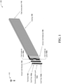
- Smart cell module 104 can comprise an intelligent (e.g., "smart") separator (e.g., interface) between cell poles 102a, 102b (e.g., external cell poles) of terminal 102 and cell material poles 106a, 106b (e.g., internal cell poles) of active cell material 106.
- Smart cell module 104 can comprise an internal circuit of device 100.
- Smart cell module 104 can comprise an integrated circuit (IC) that can be formed on a substrate (e.g., a silicon (Si) substrate, etc.) using one or more fabrication techniques and/or materials described below.
- IC integrated circuit
- small cell module 104 can be fabricated on a substrate (e.g., a silicon (Si) substrate, etc.) by employing techniques including, but not limited to: photolithography, microlithography, nanolithography, nanoimprint lithography, photomasking techniques, patterning techniques, photoresist techniques (e.g., positive-tone photoresist, negative-tone photoresist, hybrid-tone photoresist, etc.), etching techniques (e.g., reactive ion etching (RIE), dry etching, wet etching, ion beam etching, plasma etching, laser ablation, etc.), evaporation techniques, sputtering techniques, plasma ashing techniques, thermal treatments (e.g., rapid thermal anneal, furnace anneals, thermal oxidation, etc.), chemical vapor deposition (CVD), atomic layer deposition (ALD), physical vapor deposition (PVD), molecular beam epitaxy (MBE), electrochemical deposition (ECD),
- Smart cell module 104 can comprise any type of component, machine, device, facility, apparatus, and/or instrument that can comprise a processor and/or can be capable of effective and/or operative communication with a wired and/or wireless network. All such embodiments are envisioned.
- smart cell module 104 can comprise a computing device, a general-purpose computer, a special-purpose computer, a quantum computing device (e.g., a quantum computer), an integrated circuit, a system on a chip (SOC), and/or another type of device.
- a computing device e.g., a quantum computer
- SOC system on a chip
- FIG. 3 illustrates an example, non-limiting circuit 300 that can facilitate an intelligent battery cell with integrated monitoring and switches in accordance with one or more embodiments described herein. Repetitive description of like elements and/or processes employed in respective embodiments is omitted for sake of brevity.
- memory 304 can store computer and/or machine readable, writable, and/or executable components and/or instructions that, when executed by processor 302, can facilitate one or more of such parameter monitoring tasks described above with reference to FIG. 1 and/or to facilitate logging of monitoring data collected by one or more sensors 306.
- memory 304 can store computer and/or machine readable, writable, and/or executable components and/or instructions that, when executed by processor 302, can facilitate operation of one or more switches 308 to configure device 100 to operate in one or more operation modes 400 described below with reference to FIG. 4 .
- memory 304 can store computer and/or machine readable, writable, and/or executable components and/or instructions such as, for instance, a machine learning component that, when executed by processor 302, can facilitate operation of one or more switches 308 (e.g., based on parameter data collected from device 100) to configure device 100 to operate in one or more operation modes 400 described below with reference to FIG. 4 .
- a machine learning component can learn to identify certain parameter data collected from device 100 that can be indicative of certain events and/or conditions associated with device 100, a battery pack comprising device 100, and/or an electronic system (e.g., an electric driveline of an EV) comprising device 100.
- the machine learning component can learn (e.g., by being trained using one or more supervised leaning techniques, unsupervised learning techniques, etc.) to identify certain parameter data that can be indicative of, for instance: a high or low state of charge (SoC) in device 100; a crash of a vehicle (e.g., an EV) comprising device 100; a high or low temperature of one or more components of device 100; a high or low pressure in device 100, and/or another event and/or condition.
- SoC state of charge
- a vehicle e.g., an EV
- One or more switches 308 can comprise MOSFET switches.
- One or more switches 308 can be configured in smart cell module 104 such that actuation of such one or more switches 308 (e.g., via processor 302) can implement one or more operation modes of device 100.
- Smart cell module 104, processor 302, memory 304, one or more sensors 306, and/or one or more switches 308 can be coupled to one another via a bus 310 to perform functions of device 100, smart cell module 104, and/or any components coupled therewith.
- Bus 310 can comprise one or more memory bus, memory controller, peripheral bus, external bus, local bus, a quantum bus, and/or another type of bus that can employ various bus architectures. Such examples of bus 310 can be employed to implement any embodiments of the subject disclosure.
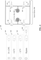
- Operation modes 400 can comprise an off mode 402 (denoted as “0V (Off)” in FIG. 4 ), a positive mode 404 (denoted as “+3.7V” in FIG. 4 ), a negative mode 406 (denoted as "-3.7V” in FIG. 4 , also referred to as a reverse mode), and/or a bypass mode 408 (denoted as "Bypass” in FIG. 4 ).
- implementation of one or more operation modes 400 defined above can enable device 100 to control (e.g., via smart cell module 104) its contribution (e.g., electric voltage contribution) to a battery pack comprising device100.
- device 100 can be configured (e.g., set) to operate in bypass mode 408 to mitigate risk of injury and/or damage to a person and/or property.
- device 100 can be configured (e.g., by operating one or more switches 308 via processor 302) to operate in bypass mode 408 to mitigate risk of injury and/or damage to a person (e.g., a technician performing the installation) and/or property (e.g., automated equipment performing the installation and/or property within a certain proximity of the electronic system).
- a person e.g., a technician performing the installation
- property e.g., automated equipment performing the installation and/or property within a certain proximity of the electronic system.
- each device 100 in a battery pack can be individually configured to operate in off mode 402, positive mode 404, negative mode 406, or bypass mode 408 to facilitate a desired yield of electric energy (e.g., electric current, electric voltage, etc.) from each device 100 and/or from the battery pack.
- one or more devices 100 in a battery pack can be individually configured (e.g., by operating one or more switches 308 via processor 302) to operate in bypass mode 408 to facilitate a desired yield of electric energy (e.g., electric current, electric voltage, etc.) from one or more other battery devices and/or battery cell devices in the battery pack.
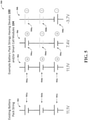
- String 504 is an electrical diagram representing an example, non-limiting battery pack string that can comprise multiple battery devices and/or battery cell devices 504a, 504b, 504c that can be coupled in series to yield, for example, 11.1V of electric voltage.
- Battery devices and/or battery cell devices 504a, 504b, 504c can each comprise the same structure and/or functionality as that of device 100 and/or smart cell module 104.
- to yield 11.1V of electric voltage for example, battery devices and/or battery cell devices 504a, 504b, 504c of string 504 can all be configured (e.g., as described above with reference to FIG. 4 ) to operate in positive mode 404.
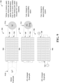
- FIG. 6 illustrates an example, non-limiting diagram 600 that can facilitate an intelligent battery cell with integrated monitoring and switches in accordance with one or more embodiments described herein. Repetitive description of like elements and/or processes employed in respective embodiments is omitted for sake of brevity.
- Diagram 600 can comprise strings 602, 604.
- Diagram 600 can further comprise a plot 606 depicting a voltage curve 608 corresponding to strings 602, 604.
- String 602 is an electrical diagram representing an example, non-limiting battery pack string that can comprise multiple battery devices and/or battery cell devices 602a, 602b, 602c that can be coupled in series to yield, for example, 7.4V of electric voltage (denoted as V 1 in FIG. 6 ).
- Battery devices and/or battery cell devices 602a, 602b, 602c can each comprise the same structure and/or functionality as that of device 100 and/or smart cell module 104.
- to yield 7.4V of electric voltage (V 1 ) for example, battery device and/or battery cell device 602b of string 602 can be configured (e.g., as described above with reference to FIG. 4 ) to operate in bypass mode 408 while battery devices and/or battery cell devices 602a and 602c can be configured to operate in positive mode 404.
- the main voltage output of a battery pack comprising one or more devices 100 and/or strings 602, 604 can be 640V, which can constitute maximum alternating current (AC) root mean square (RMS) values that can be produced by strings 602, 604 with 400V DC supplied by each string.
- AC alternating current
- RMS root mean square
- the AC RMS value will be the same, that is, for instance, it will be 640V.
- FIG. 8 illustrates an example, non-limiting diagram 800 that can facilitate an intelligent battery cell with integrated monitoring and switches in accordance with one or more embodiments described herein. Repetitive description of like elements and/or processes employed in respective embodiments is omitted for sake of brevity.
- String 804 is an electrical diagram representing an example, non-limiting battery pack string that can comprise multiple battery devices and/or battery cell devices 804a, 804b, 804c that can be coupled in series to yield, for example, 0.0V of electric voltage.
- Battery devices and/or battery cell devices 804a, 804b, 804c can each comprise the same structure and/or functionality as that of device 100 and/or smart cell module 104.
- FIG. 8 to yield 0.0V of electric voltage, for example, all battery devices and/or battery cell devices 804a, 804b, 804c of string 804 can be configured (e.g., as described above with reference to FIG. 4 ) to operate in bypass mode 408.
- Voltage curves 810, 812, 814 can each comprise an example, non-limiting alternative embodiment of voltage curve 608, 702, and/or 704, where voltage curves 810, 812, 814 can be generated based on electric voltages that can be yielded by strings 802, 804, 806, respectively.
- voltage curves 810, 812, 814 can be generated using steps 706 as described above with reference to FIG. 7 , where each step 706 of each voltage curve 810, 812, 814 can represent an electric voltage yielded by a single device 100 in each of strings 802, 804, 806.
- each device 100 of each string 910 in battery pack 908 of electronic system 904 can be individually configured to operate in off mode 402, positive mode 404, negative mode 406, or bypass mode 408 such that battery pack 908 can be coupled to an AC charger 914 (denoted as "AC Chrg" in FIG. 9 ) to enable AC charging of battery pack 908 of electronic system 904 (e.g., AC charging to approximately 400V as illustrated in FIG. 9 ).
- AC charger 914 can comprise an AC charger including, but not limited to, a single-phase AC charger, a 3-phase AC charger, and/or another type of AC charger.
- Electronic system 906 can comprise battery pack 908.
- Battery pack 908 of electronic system 906 can comprise multiple devices 100 (e.g., 42 devices 100) that be coupled to one another in series to form multiple strings 910 (e.g., 3 strings 910).
- Strings 910 of electronic system 906 can be coupled to one another in series as illustrated in FIG. 9 .
- Each device 100 of each string 910 in battery pack 908 of electronic system 906 can be individually configured to operate in a certain operation mode 400 (e.g., as described above with reference to FIG. 4 ) to yield a desired electric voltage (e.g., a certain positive or negative electric voltage value).
- each device 100 of each string 910 in battery pack 908 of electronic system 906 can be individually configured to operate in off mode 402, positive mode 404, negative mode 406, or bypass mode 408 such that battery pack 908 can be coupled to a DC charger (not illustrated in FIG. 9 ) to enable DC charging of battery pack 908 of electronic system 906 (e.g., DC charging to approximately 1200V as illustrated in FIG. 9 ).
- a DC charger not illustrated in FIG. 9
- Electronic system 1000a can comprise an example, non-limiting alternative embodiment of electronic system 902 described above with reference to FIG. 9 .
- electronic system 1000a can comprise an electric driveline that can be implemented in an EV to, for example, provide electric power (e.g., AC or DC) directly (e.g., without the use of, for instance, an inverter) to one or more electronic components in the EV (e.g., motor 912a) and/or to enable a battery pack of the electric driveline to be charged using an AC or DC charger.
- electric power e.g., AC or DC
- Electronic system 1000a can comprise battery pack 908.
- Battery pack 908 of electronic system 1000a can comprise multiple devices 100 (e.g., 42 devices 100) that be coupled to one another in series to form multiple strings 910 (e.g., 3 strings 910).
- Strings 910 of electronic system 1000a can be coupled to one another in parallel as illustrated in FIG. 10A .
- Each device 100 of each string 910 in battery pack 908 of electronic system 1000a can be individually configured to operate in a certain operation mode 400 (e.g., as described above with reference to FIG. 4 ) to yield a desired electric voltage (e.g., a certain positive or negative electric voltage value).
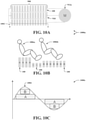
- each device 100 can communicate with all other devices 100 in battery pack 908 (e.g., wirelessly via smart cell module 104, network 112, etc.) to, for instance: determine each other's SoC status; exchange each other's assigned duty cycles; and/or exchange revised duty cycles of one or more certain devices 100 that can be modified based on, for instance, a change in the SoC status of one or more other devices 100 in battery pack 908.
- battery pack 908 e.g., wirelessly via smart cell module 104, network 112, etc.
- such a control unit can define a duty cycle for a device 100 denoted in FIG. 10C as "A” that is longer in duration than that of a duty cycle for device 100 denoted in FIG. 10C as "B.”
- Device 1100c comprises a battery pack 1102c having multiple devices 100.
- Battery pack 1102c can comprise the same structure and/or functionality as that of battery pack 908 described above with reference to FIGS. 9 , 10A, 10B, and 10C .
- device 1100c illustrates how the electric energy (e.g., electric voltage, electric current, etc.) of each device 100 in battery pack 1102c can be used (e.g., discharged) to its full extent.
- the duty cycle defined for each device 100 in battery pack 1102c can dictate how much electric energy (e.g., electric voltage, electric current, etc.) of each device 100 is used (e.g., discharged). Therefore, the electric energy (e.g., electric voltage, electric current, etc.) of each device 100 in battery pack 1102c can be used (e.g., discharged) to its full extent (e.g., all or nearly all electric energy of each device 100 can be used). Consequently, it should be appreciated that the variation in electrical capacity of each device 100 in battery pack 1102c illustrated in FIG. 11C will not be a limit to the electrical capacity of battery pack 1102c.
- a certain device 100 in battery pack 1102c can determine (e.g., via one or more sensors 306 of smart cell module 104) that its electric energy is at or approaching a defined low level (e.g., a target SoC percentage) and can further communicate such information to a control unit that can be coupled to battery pack 1102c (e.g., the control unit described above with reference to FIGS. 10A, 10B, and 10C ).
- this certain device 100 e.g., via smart cell module 104 and/or the control unit can modify the duty cycle corresponding to such a certain device 100.
- this certain device 100 (e.g., via smart cell module 104) and/or the control unit can reduce the duration of the duty cycle corresponding to this certain device 100 such that less electric energy is discharged from this certain device 100.
- Battery pack 1102c can be discharged at a discharge amount (e.g., discharge rate, discharge voltage, discharge current, etc.) that can be determined based on a target SoC percentage and/or a cell priority stack corresponding to devices 100 in battery pack 1102c. Additionally, or alternatively, each device 100 in battery pack 1102c can comprise a modular component that can function and/or be controlled independent of all other devices 100 in battery pack 1102c.
- a discharge amount e.g., discharge rate, discharge voltage, discharge current, etc.
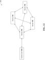
- FIG. 12 illustrates an example, non-limiting system 1200 that can facilitate an intelligent battery cell with integrated monitoring and switches in accordance with one or more embodiments described herein. Repetitive description of like elements and/or processes employed in respective embodiments is omitted for sake of brevity.
- control unit 1202 can request, and/or each device 100 can periodically provide (e.g., every minute), parameter data (e.g., electric voltage, frequency, temperature, chemistry, etc.) from each device 100 that can be obtained by each such device 100 (e.g., via smart cell module 104 and/or one or more sensors 306 as described above with reference to FIG. 1 ).
- parameter data e.g., electric voltage, frequency, temperature, chemistry, etc.
- control unit 1202 can comprise a VCU (e.g., the VCU described above with reference to FIGS. 10A, 10B, and 10C ) that can be implemented in and/or coupled to an electric driveline of an EV.
- control unit 1202 can comprise and/or employ a BMS that can individually control (e.g., via smart cell module 104) functionality of each device 100 and/or functionality of a battery pack (e.g., battery pack 908) that can comprise one or more devices 100.
- control unit 1202 can perform one or more operations (e.g., operation mode reconfiguration, modify discharge priorities, etc.) to ensure a battery pack (e.g., battery pack 908) that can comprise devices 100 can maintain its discharge amount (e.g., discharge rate, discharge voltage, discharge current, etc.).
- operations e.g., operation mode reconfiguration, modify discharge priorities, etc.
- battery pack e.g., battery pack 908
- discharge amount e.g., discharge rate, discharge voltage, discharge current, etc.
- system 1200 can facilitate elimination of one or more computing devices and/or communication devices associated with and/or located in the EV, as the functionality of such devices can be transferred to control unit 1202 and/or one or more devices 100 of system 1200.
- device 100 can comprise a DC supply section (not illustrated in FIG. 1 ).
- circuit 1300 can comprise an electrical circuit representation of such a device 100 that can comprise a DC supply section.
- circuit 1300 can comprise an example, non-limiting alternative embodiment of circuit 300 described above with reference to FIG. 3 , where circuit 1300 can comprise a DC supply section 1302 as illustrated in the example embodiment depicted in FIG. 13 .
- Transformer 1304 can comprise a push-pull transformer or another transformer. Transformer 1304 can enable coupling (e.g., via cell poles 1306a, 1306b) of a DC electronic device to a device 100 that comprises DC supply section 1302, where such DC coupling of the DC electronic device can be independent from and/or insulated from (e.g., electrically independent from and/or electrically insulated from) the AC supply that can be provided using device 100 (e.g., as described above with reference to FIGS. 3-9 ). Transformer 1304 can be controlled (e.g., operated) by processor 302 using one or more switches 308 of DC supply section 1302.
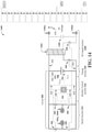
- FIG. 14 illustrates an example, non-limiting circuit 1400 that can facilitate an intelligent battery cell with integrated monitoring and switches in accordance with one or more embodiments described herein. Repetitive description of like elements and/or processes employed in respective embodiments is omitted for sake of brevity.
- device 100 can comprise a DC supply section (not illustrated in FIG. 1 ).
- circuit 1400 can comprise an electrical circuit representation of such a device 100 that can comprise a DC supply section.
- circuit 1400 can comprise an example, non-limiting alternative embodiment of circuit 300 and/or circuit 1300 described above with reference to FIGS. 3 and 13 , respectively, where circuit 1400 can comprise a DC supply section 1402 as illustrated in the example embodiment depicted in FIG. 14 .
- the transformer ratio of transformer 1404 can comprise any ratio value that can enable a device 100 comprising DC supply section 1404 to yield a constant DC electric voltage ranging from, for example, approximately 4V to approximately 6V.
- the transformer ratio of transformer 1404 can comprise a 1:2 ratio.
- the transformer ratio of transformer 1404 can be adjusted to yield a desired constant DC electric voltage value.
- the DC electric voltage that can be yielded at cell poles 1306a, 1306b can be controlled by the duty cycle(s) corresponding to one or more switches 308 of DC supply section 1402 as described above, where such one or more switches 308 of DC supply section 1402 can be operated (e.g., opened, closed, turned on, turned off, engaged, disengaged, etc.) by processor 302.
- a device 100 comprising DC supply section 1402 can provide AC electric power (e.g., as described above with reference to FIGS. 3-9 ) to operate one or more motors of the EV (e.g., AC electric power to drive the EV) and DC electric power to operate one or more auxiliary electronic systems of the electric driveline and/or the EV, thereby enabling elimination of one or more electronic components associated with such one or more auxiliary electronic systems, the electric driveline, and/or the EV.
- AC electric power e.g., as described above with reference to FIGS. 3-9
- such a device 100 comprising DC supply section 1402 can provide DC electric power to operate one or more auxiliary electronic systems in the EV such as, for example, a heating, ventilation, and air conditioning (HVAC) system, interior and/or exterior lighting systems, electrically powered windows and/or locks, audio systems, DC electric power supply ports, windshield wipers, and/or another auxiliary electronic system in the EV.
- HVAC heating, ventilation, and air conditioning
- such a device 100 comprising DC supply section 1402 can thereby enable elimination of one or more electronic components including, but not limited to, a converter, an inverter, one or more DC batteries, and/or another component associated with such one or more auxiliary electronic systems, the electric driveline, and/or the EV.
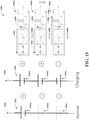
- String 1504 is an electrical diagram representing an example, non-limiting battery pack string that can comprise multiple battery devices and/or battery cell devices 1504a, 1504b, 1504c that can be coupled in series to yield a certain electric voltage.
- Battery devices and/or battery cell devices 1504a, 1504b, 1504c can each comprise the same structure and/or functionality as that of device 100 and/or smart cell module 104.
- String 1504 can illustrate the direction of energy flow in a charging mode (e.g., a reverse mode), where the energy flow direction is represented by arrow 1508 as depicted in the example embodiment shown in FIG. 15 .
- each battery device and/or battery cell device 1504a, 1504b, 1504c of string 1504 can comprise the same structure and/or functionality as that of a device 100 comprising DC supply section 1402, and string 1504 comprising such devices can be implemented in a battery pack (e.g., battery pack 908).
- a battery pack e.g., battery pack 908
- a DC electric load e.g., 12V load, 48V load, etc.
- electric energy can be transferred between battery devices and/or battery cell devices 1504a, 1504b, 1504c in the charging mode (e.g., transferred on the AC supply side of such devices) as illustrated by string 1504 and energy flow diagrams 1506a, 1506b, 1506c illustrated in FIG. 15 .
- the above described battery pack e.g., battery pack 908 that can comprise string 1504 can be implemented in an electric driveline of an EV.
- such electric energy transfer described above can also be implemented, for instance, when the EV is static (e.g., in standstill, in parked position, motionless, etc.) and/or when the AC supply side of the above described battery pack and/or battery devices and/or battery cell devices 1504a, 1504b, 1504c is not operating (e.g., not propelling the EV or charging).
- the 3-phases of the 3-phase AC supply described above with reference to FIGS. 3-9 must not create a rotating magnetic field.
- FIG. 16 illustrates an example, non-limiting circuit 1600 that can facilitate an intelligent battery cell with integrated monitoring and switches in accordance with one or more embodiments described herein. Repetitive description of like elements and/or processes employed in respective embodiments is omitted for sake of brevity.
- device 100 can comprise multiple active cell material 106 (e.g., multiple battery cells) that can be coupled to the same smart cell module 104 in device 100.
- circuit 1600 can comprise an electrical circuit representation of such a device 100 that can comprise multiple active cell material 106 (e.g., multiple battery cells) that can be coupled to the same smart cell module 104.
- circuit 1600 can comprise an example, non-limiting alternative embodiment of circuit 300, circuit 1300, and/or circuit 1400 described above with reference to FIGS. 3 , 13 , and 14 , respectively, where circuit 1600 can comprise multiple active cell material 106 (e.g., 3 battery cells) that can be coupled to the same smart cell module 104 in a device 100 as illustrated in the example embodiment depicted in FIG. 16 .
- device 100 can comprise, for instance, three active cell material 106 that can be coupled to the same smart cell module 104.
- active cell material 106 can be coupled to one another in series and coupled to the same smart cell module 104 in parallel (e.g., via one or more components that can facilitate internal balancing (e.g., internal load balancing) as illustrated in FIG. 16 ).
- such a device 100 that can comprise multiple active cell material 106 that can be coupled to the same smart cell module 104 in device 100 can enable elimination of one or more components associated with an electronic system comprising such a device 100 (e.g., by simultaneously providing DC power supply and AC power supply as described above with reference to FIGS. 13 and 14 ).
- FIG. 17 illustrates an example, non-limiting wire diagram 1700 that can facilitate an intelligent battery cell with integrated monitoring and switches in accordance with one or more embodiments described herein. Repetitive description of like elements and/or processes employed in respective embodiments is omitted for sake of brevity.
- Wire diagram 1700 illustrates how one or more embodiments of the subject disclosure can be implemented in an electrical system to facilitate one or more functions of such one or more embodiments described above with reference to FIGS. 1-16 .
- wire diagram 1700 illustrates how one or more embodiments of the subject disclosure can be implemented in, for example, an electric driveline of an EV to facilitate one or more functions of such one or more embodiments described above with reference to FIGS. 1-16 .
- an isolated DC power supply (e.g., 12V, 48V, 360V, etc.) can be extracted (e.g., via cell poles 1306a, 1306b) from a battery pack 1702 of wire diagram 1700.
- Battery pack 1702 can comprise multiple devices 100 comprising DC supply section 1302 and/or DC supply section 1402. For clarity, only one of such devices 100 is identified in wire diagram 1700 depicted in FIG. 17 .
- Battery pack 1702 can comprise the same structure and/or functionality as that of battery pack 908 described above with reference to FIG. 9 .
- an isolated AC power supply can be extracted from battery pack 1702 of wire diagram 1700.
- Such an isolated AC power supply can be extracted from battery pack 1702 by, for instance: respectively configuring (e.g., via processor 302) one or more devices 100 of battery pack 1702 in a certain operation mode 400 (e.g., off mode 402, positive mode 404, negative mode 406, or bypass mode 408) as described above with reference to FIGS.
- a certain operation mode 400 e.g., off mode 402, positive mode 404, negative mode 406, or bypass mode 408
- AC electric energy can be used as AC propulsion energy to power one or more motors M1, M2, M3 shown in wire diagram 1700, where such one or more motors M1, M2, M3 can be used to propel (e.g., drive) the EV.
- one or more of such devices 100 described above and/or one or more switches 1704 can be configured and/or operated such that this AC power supply can be provided to one or more motors M1, M2, M3 at the same time (e.g., simultaneously, in parallel, etc.) as the above described isolated DC power supply is provided (e.g., at the same time the isolated DC power supply is provided to cell poles 1306a, 1306b).
- AC charger 914 can be coupled to battery pack 1702 of wire diagram 1700 to charge battery pack 1702 and/or one or more of such devices 100 described above using an AC power supply from AC charger 914.
- AC charger 914 can charge battery pack 1702 and/or one or more of such devices 100 described above by, for instance: respectively configuring (e.g., via processor 302) one or more devices 100 of battery pack 1702 in a certain operation mode 400 (e.g., off mode 402, positive mode 404, negative mode 406, or bypass mode 408) as described above with reference to FIGS.
- a certain operation mode 400 e.g., off mode 402, positive mode 404, negative mode 406, or bypass mode 408 as described above with reference to FIGS.
- one or more of such devices 100 described above and/or one or more switches 1704 can be configured and/or operated such that the AC power supply from AC charger 914 can be provided to battery pack 1702 and/or such one or more devices 100 at the same time (e.g., simultaneously, in parallel, etc.) as the above described isolated DC power supply is provided (e.g., at the same time the isolated DC power supply is provided to cell poles 1306a, 1306b).
- FIG. 18 illustrates an example, non-limiting diagram 1800 that can facilitate an intelligent battery cell with integrated monitoring and switches in accordance with one or more embodiments described herein. Repetitive description of like elements and/or processes employed in respective embodiments is omitted for sake of brevity.
- Low level 1802 can comprise low complexity functions that can be performed by, for instance, implementing one or more software applications that can facilitate such low complexity functions in low level 1802.
- one or more software applications that can comprise a low level of complexity can be implemented to facilitate one or more functions of low level 1802 including, but not limited to: generating 3-phase (denoted as "Generate 3-phase” in FIG. 18 ); H-bridge control (denoted as “H-bridge ctrl” in FIG. 18 ); cell communication (denoted as “Cell Comm” in FIG. 18 ); flyback control (denoted as “Flyback ctrl” in FIG. 18 ); diagnostics (denoted as "Diagnostic” in FIG. 18 ); sensor reading; over-the-air updates (denoted as "OtA update” in FIG. 18 ); and/or another function.
- Medium level 1804 can comprise medium complexity functions that can be performed by, for instance, implementing one or more software applications that can facilitate such medium complexity functions in medium level 1804.
- one or more software applications that can comprise a medium level of complexity can be implemented to facilitate one or more functions of medium level 1804 including, but not limited to: processing torque (denoted as "Process Torque” in FIG. 18 ); charge control (denoted as “Charge ctrl” in FIG. 18 ); cross-cell communication (denoted as "X-Cell Comm” in FIG. 18 ); low voltage processing (denoted as "LV processing” in FIG. 18 ); diagnostics (denoted as "Diagnostic” in FIG.
- High level 1806 can comprise high complexity functions that can be performed by, for instance, implementing one or more software applications that can facilitate such high complexity functions in high level 1806.
- one or more software applications that can comprise a high level of complexity can be implemented to facilitate one or more functions of high level 1806 including, but not limited to: vehicle interface (denoted as "Veh. Interface” in FIG. 18 ); charge interface (denoted as “Charge Interface” in FIG. 18 ); vehicle communication (denoted as “Veh Comm” in FIG. 18 ); low voltage interface (denoted as “LV Interface” in FIG. 18 ); diagnostics (denoted as "Diagnostic” in FIG. 18 ); energy optimization (denoted as "Energy optim” in FIG. 18 ); root mean square (RMS) limit (denoted as “RMS limit etc” in FIG. 18 ); over-the-air updates (denoted as "OtA update” in FIG. 18 ); and/or another function.
- vehicle interface denoted as "Ve
- computer-implemented method 1900 can comprise coupling, by a system (e.g., via device 100, smart cell module 104, etc.) operatively coupled to a processor (e.g., processor 302), one or more switches (e.g., one or more switches 308) of an internal circuit (e.g., smart cell module 104) integrated in a battery cell device (e.g., device 100) to battery cell poles (e.g., cell poles 102a, 102b) of the battery cell device.
- a system e.g., via device 100, smart cell module 104, etc.
- a processor e.g., processor 302
- switches e.g., one or more switches 308 of an internal circuit (e.g., smart cell module 104) integrated in a battery cell device (e.g., device 100)
- battery cell poles e.g., cell poles 102a, 102b
- computer-implemented method 1900 can comprise providing, by the system (e.g., via device 100, smart cell module 104, etc.), a defined value (e.g., a value of zero (0), a positive value, a negative value, etc.) of electric potential at the battery cell poles based on the coupling.
- a defined value e.g., a value of zero (0), a positive value, a negative value, etc.
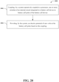
- FIG. 20 illustrates a flow diagram of an example, non-limiting computer-implemented method 2000 that can facilitate an intelligent battery cell with integrated monitoring and switches in accordance with one or more embodiments described herein. Repetitive description of like elements and/or processes employed in respective embodiments is omitted for sake of brevity.
- computer-implemented method 2000 can comprise providing, by the system (e.g., via device 100, smart cell module 104, etc.) an electric potential of zero volts at the battery cell poles based on the coupling.
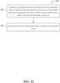
- computer-implemented method 2100 can comprise providing, by a system (e.g., via a system comprising a computer coupled to device 100, smart cell module 104, and/or machinery (e.g., manufacturing equipment) operated by the computer to fabricate and/or maintain a battery pack comprising device 100) operatively coupled to a processor (e.g., processor 302), an electric potential of zero volts at battery cell poles (e.g., cell poles 102a, 102b) of one or more battery cell devices (e.g., one or more devices 100) in a battery pack (e.g., battery pack 908).
- a system e.g., via a system comprising a computer coupled to device 100, smart cell module 104, and/or machinery (e.g., manufacturing equipment) operated by the computer to fabricate and/or maintain a battery pack comprising device 100
- a processor e.g., processor 302
- an electric potential of zero volts at battery cell poles e.g
- FIG. 22 illustrates a flow diagram of an example, non-limiting computer-implemented method 2200 that can facilitate an intelligent battery cell with integrated monitoring and switches in accordance with one or more embodiments described herein. Repetitive description of like elements and/or processes employed in respective embodiments is omitted for sake of brevity.
- computer-implemented method 2200 can comprise collecting, by a system (e.g., via device 100, smart cell module 104, one or more sensors 306, etc.) operatively coupled to a processor (e.g., processor 302), parameter data (e.g., parameter data defined above with reference to FIG. 1 such as, for instance, temperature, pressure, chemistry, acceleration, current, voltage, etc.) of a battery cell device (e.g., device 100) using one or more sensors (e.g., one or more sensors 306) of an internal circuit (e.g., smart cell module 104) that is integrated in the battery cell device and coupled to active battery cell material (e.g., active cell material 106) of the battery cell device.
- a system e.g., via device 100, smart cell module 104, one or more sensors 306, etc.
- parameter data e.g., parameter data defined above with reference to FIG. 1 such as, for instance, temperature, pressure, chemistry, acceleration, current, voltage, etc.
- FIG. 23 illustrates a flow diagram of an example, non-limiting computer-implemented method 2300 that can facilitate an intelligent battery cell with integrated monitoring and switches in accordance with one or more embodiments described herein. Repetitive description of like elements and/or processes employed in respective embodiments is omitted for sake of brevity.
- computer-implemented method 2300 can comprise coupling, by a system (e.g., via a system such as, for instance, an electric driveline in an EV that comprises control unit 1202 coupled to battery pack 908, device 100, and/or smart cell module 104) operatively coupled to a processor (e.g., control unit 1202, processor 302, etc.), one or more switches (e.g., one or more switches 1704) of an electronic system (e.g., an electric driveline in an EV) to a battery pack (e.g., battery pack 908) comprising multiple battery cell devices (e.g., multiple devices 100) coupled to one another in parallel and in series (e.g., as described above with reference to FIGS. 3-9 and 13-17 and as illustrated by wire diagram 1700 depicted in FIG. 17 ).
- a system e.g., via a system such as, for instance, an electric driveline in an EV that comprises control unit 1202 coupled to battery pack 908, device 100, and/or smart cell module 10
- computer-implemented method 2400 can comprise coupling, by a system (e.g., via a system such as, for instance, an electric driveline in an EV that comprises control unit 1202 coupled to battery pack 908, device 100, and/or smart cell module 104) operatively coupled to a processor (e.g., control unit 1202, processor 302, etc.), one or more switches (e.g., one or more switches 1704) of an electric driveline in an electric vehicle (EV) to a battery pack (e.g., battery pack 908) that is positioned in the EV and that comprises multiple battery cell devices (e.g., multiple devices 100) coupled to one another in parallel and in series (e.g., as described above with reference to FIGS. 3-9 and 13-17 and as illustrated by wire diagram 1700 depicted in FIG. 17 ).
- a system e.g., via a system such as, for instance, an electric driveline in an EV that comprises control unit 1202 coupled to battery pack 908, device 100, and/or smart cell module 10
- computer-implemented method 2400 can comprise providing, by the system (e.g., via a system such as, for instance, an electric driveline in an EV that comprises control unit 1202 coupled to battery pack 908, device 100, and/or smart cell module 104), providing, by the system, based on the coupling, a direct current (DC) energy supply from the battery pack when the electric vehicle is at a standstill (e.g., when the EV is static, motionless, parked, etc.) by using an alternating current (AC) energy supply of the battery pack (e.g., as described above with reference to FIG. 17 ).
- DC direct current
- AC alternating current
- FIG. 25 illustrates a flow diagram of an example, non-limiting computer-implemented method 2500 that can facilitate an intelligent battery cell with integrated monitoring and switches in accordance with one or more embodiments described herein. Repetitive description of like elements and/or processes employed in respective embodiments is omitted for sake of brevity.
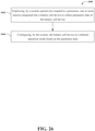
- FIG. 26 illustrates a flow diagram of an example, non-limiting computer-implemented method 2600 that can facilitate an intelligent battery cell with integrated monitoring and switches in accordance with one or more embodiments described herein. Repetitive description of like elements and/or processes employed in respective embodiments is omitted for sake of brevity.
- computer-implemented method 2600 can comprise configuring, by the system (e.g., via device 100, smart cell module 104, the machine learning component described above with reference to FIG. 1 , etc.), the battery cell device in a defined operation mode (e.g., off mode 402, positive mode 404, negative mode 406, bypass mode 408, etc.) based on the parameter data.
- a defined operation mode e.g., off mode 402, positive mode 404, negative mode 406, bypass mode 408, etc.
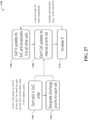
- FIG. 27 illustrates a flow diagram of an example, non-limiting computer-implemented method 2700 that can facilitate an intelligent battery cell with integrated monitoring and switches in accordance with one or more embodiments described herein. Repetitive description of like elements and/or processes employed in respective embodiments is omitted for sake of brevity.
- computer-implemented method 2700 can comprise sorting cells (e.g., devices 100) in SoC order.
- each device 100 in a battery pack e.g., battery pack 908
- can store e.g., on memory 304)
- a record e.g., a list, a database, etc.
- the multiple devices 100 in such a battery pack can collectively constitute, for instance, a multicore processing system and/or a distributed computing network system.
- such a record can constitute an original record that can be generated at a certain time to (e.g., at the start of computer-implemented method 2700), where such a record can comprise an original SoC of each device 100 that can be determined at such a certain time to (e.g., each device 100 can send its original SoC to all other devices 100 in the battery pack at such a certain time to and each device 100 can generate such a record comprising the SoC status of all devices 100).
- each device 100 can sort (e.g., rank) all devices 100 in the battery pack according to the SoC of each device 100. For instance, each device 100 can rank all devices 100 in order from highest SoC to lowest SoC or vice versa.
- computer-implemented method 2700 can comprise designating discharge priority for each cell (e.g., for each device 100).
- each device 100 in a battery pack e.g., battery pack 908
- can store e.g., on memory 304)
- a record e.g., a list, a database, etc.
- a discharge priority can be generated and/or revised by each device 100 based on the SoC status of all devices 100 in the battery pack.
- such a certain device 100 that can be denoted as "N” can periodically (e.g., every second) update its current SoC status on the record it can store on memory 304 as described above at 2702.
- Each device 100 in the battery pack can further distribute to all devices 100 in the battery pack its revised SoC status and/or a revised version of the record described above at 2702 comprising the SoC status of each device 100 in the battery pack, where such a revised version of such a record can comprise the revised SoC status of such a certain device 100 that can be denoted as "N.”
- computer-implemented method 2700 can comprise increasing N (e.g., increasing, by the certain device 100 that can be denoted as "N," the duty cycle of such a certain device 100).
- N the duty cycle of such a certain device 100.
- each device 100 in a battery pack e.g., battery pack 908
- can control e.g., increase, decrease, etc.
- its own electrical power output e.g., AC and/or DC power output, as described above with reference to FIGS. 1-10C
- such a certain device 100 that can be denoted as "N” can increase its own duty cycle (e.g., amplitude, duration, etc.).
- steps 2706 to 2710 can be repeated periodically (e.g., every second) to, for instance, maintain a certain electrical output (e.g., AC and/or DC electrical output) of the respective devices 100 and/or a certain electrical output of the battery pack.
- a certain electrical output e.g., AC and/or DC electrical output
- computer-implemented method 2700 can be implemented as a balancing algorithm (e.g., a distributed algorithm).
- computer-implemented method 2700 can be implemented to balance (e.g., modify, adjust, etc.) the electric power output (e.g., AC and/or DC power output) of each device 100 in a battery pack (e.g., battery pack 908) and/or to balance (e.g., modify, adjust, etc.) the electric power output (e.g., AC and/or DC power output) of the battery pack.
- computer-implemented method 2700 can be implemented to perform such balancing of the electric power output of each device 100 and/or the electric power output of such a battery pack comprising multiple devices 100 without using a control unit (e.g., a VCU) to facilitate such balancing.
- a control unit e.g., a VCU
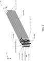
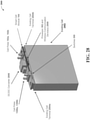
- FIG. 28 illustrates an orthogonal view of an example, non-limiting device 2800 that can facilitate an intelligent battery cell with integrated monitoring and switches in accordance with one or more embodiments described herein. Repetitive description of like elements and/or processes employed in respective embodiments is omitted for sake of brevity.
- Device 2800 illustrated in FIG. 28 can comprise an example, non-limiting alternative embodiment of device 100 described above with reference to FIG. 1 .
- device 2800 can comprise an existing cell 2802 having smart cell module 104 coupled thereto (e.g., where smart cell module 104 can comprise an add-on component that can be coupled to an already existing battery cell (e.g., a standard battery cell) denoted as existing cell 2802 in FIG. 28 ).
- existing cell 2802 can comprise the same structure and/or functionality as that of active cell material 106 described above with reference to FIG. 1 .
- smart cell module 104 can be coupled to existing cell 2802 via existing cell terminals 2804a, 2804b.
- Existing cell terminals 2804a, 2804b can comprise the same structure and/or functionality as that of cell material poles 106a, 106b described above with reference to FIG. 1 .
- cell poles 102a, 102b e.g., DC terminals
- cell poles 1306a, 1306b e.g., AC terminals
- cell poles 102a, 102b e.g., DC terminals
- cell poles 1306a, 1306b e.g., AC terminals
- cell poles 102a, 102b can be formed on and/or coupled to smart cell module 104 at another location on smart cell module 104 and/or in another orientation.
- Device 2800 can further comprise a converter such as, for instance, a DC/DC converter 2806 that can be coupled to, formed on, and/or integrated with smart cell module 104.
- DC/DC converter 2806 can be coupled to one or more components of device 100 and/or smart cell module 104 (e.g., to cell poles 102a, 102b, one or more switches 308, etc.).
- DC/DC converter 2806 can comprise a DC/DC converter or another type of converter.
- DC/DC converter 2806 can be coupled to smart cell module 104, for example, as illustrated in FIG. 28 .
- DC/DC converter 2806 can be coupled to smart cell module 104 at another location on smart cell module 104 and/or in another orientation (e.g., vertically, etc.).
- DC/DC converter 2806 can convert a source of DC voltage that can be yielded by device 100 and/or smart cell module 104 from one voltage level to another voltage level (e.g., from a lower DC voltage level to a higher DC voltage level or vice versa).
- a battery pack e.g., battery pack 908 that can comprise multiple device 100 can also comprise DC/DC converter 2806.
- DC/DC converter 2806 can convert a source of DC voltage that can be yielded by such a battery pack (e.g., a source of DC voltage that can be yielded by one or more devices 100 in the battery pack) from one voltage level to another voltage level (e.g., from a lower DC voltage level to a higher DC voltage level or vice versa).
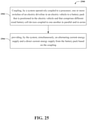
- FIG. 29 illustrates a flow diagram of an example, non-limiting computer-implemented method 2900 that can facilitate an intelligent battery cell with integrated monitoring and switches in accordance with one or more embodiments described herein. Repetitive description of like elements and/or processes employed in respective embodiments is omitted for sake of brevity.
- computer-implemented method 2900 can comprise operating, by a system (e.g., via device 100, smart cell module 104, processor 302, etc.) operatively coupled to a processor (e.g., processor 302), one or more sensors (e.g., one or more sensors 306) of an internal circuit (e.g., smart cell module 104) that is integrated in a battery cell device (e.g., device 100) and coupled to active battery cell material (e.g., active cell material 106) of the battery cell device.
- a system e.g., via device 100, smart cell module 104, processor 302, etc.
- a processor e.g., processor 302
- sensors e.g., one or more sensors 306 of an internal circuit
- a battery cell device e.g., device 100
- active battery cell material e.g., active cell material 106
- computer-implemented method 2900 can comprise monitoring, by the system (e.g., via device 100, smart cell module 104, processor 302, one or more sensors 306, etc.), one or more parameters (e.g., parameter data defined above with reference to FIG. 1 such as, for instance, temperature, pressure, chemistry, acceleration, current, voltage, etc.) of the battery cell device based on the operating.
- the system e.g., via device 100, smart cell module 104, processor 302, one or more sensors 306, etc.
- parameters e.g., parameter data defined above with reference to FIG. 1 such as, for instance, temperature, pressure, chemistry, acceleration, current, voltage, etc.
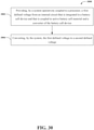
- FIG. 30 illustrates a flow diagram of an example, non-limiting computer-implemented method 3000 that can facilitate an intelligent battery cell with integrated monitoring and switches in accordance with one or more embodiments described herein. Repetitive description of like elements and/or processes employed in respective embodiments is omitted for sake of brevity.
- computer-implemented method 3000 can comprise providing, by a system (e.g., via device 100, smart cell module 104, processor 302, one or more switches 308, etc.) operatively coupled to a processor (e.g., processor 302), a first defined voltage (e.g., a low voltage, a high voltage, etc.) from an internal circuit (e.g., smart cell module 104) that is integrated in a battery cell device (e.g., device 100) and that is coupled to active battery cell material (e.g., active cell material 106) and a converter (e.g., DC/DC converter 2806) of the battery cell device.
- a system e.g., via device 100, smart cell module 104, processor 302, one or more switches 308, etc.
- a processor e.g., processor 302
- a first defined voltage e.g., a low voltage, a high voltage, etc.
- an internal circuit e.g., smart cell module 104
- computer-implemented method 3000 can comprise converting, by the system (e.g., via device 100, smart cell module 104, processor 302, one or more switches 308, DC/DC converter 2806, etc.), the first defined voltage to a second defined voltage (e.g., a high voltage, a low voltage, etc.).
- a second defined voltage e.g., a high voltage, a low voltage, etc.
- the various embodiments of the subject disclosure described herein can be associated with battery device and/or battery cell device technologies, battery pack technologies, battery management system (BMS) technologies, electric driveline technologies, electric vehicle technologies, semiconducting and/or superconducting circuit technologies, computing device and/or communication device technologies, machine learning technologies, artificial intelligence technologies, cloud computing technologies, and/or other technologies.
- BMS battery management system
- the various embodiments of the subject disclosure described herein can provide technical improvements to systems, devices, components, operational steps, and/or processing steps associated with the various technologies identified above.
- the various embodiments of the subject disclosure described herein e.g., devices 100, 200, 2800, circuits 300, 1300, 1400, 1600, electronic systems 902, 904, 906, 1000a, battery pack 1102c, system 1200, wire diagram 1700, etc.
- the various embodiments of the subject disclosure described herein e.g., devices 100, 200, 2800, circuits 300, 1300, 1400, 1600, electronic systems 902, 904, 906, 1000a, battery pack 1102c, system 1200, wire diagram 1700, etc.
- a battery cell device e.g., device 100
- can monitor e.g., via one or more sensors 306) and/or log itself using an internal circuit (e.g., smart cell module 104) comprising a processor (e.g., processor 302) and a memory (e.g., memory 304).
- the battery cell device e.g., device 100
- can control its connection e.g., via one or more switches 308 to other battery cell devices (e.g., to one or more other devices 100) using different operation modes (e.g., off mode 402, positive mode 404, negative mode 406, or bypass mode 408).
- a battery pack comprising the battery cell device (e.g., battery pack 908) to vary in voltage and/or to provide an AC and/or DC power supply, thereby eliminating the need for many auxiliary systems (e.g., converter, inverter, DC battery, etc.) in an electronic system (e.g., an electric driveline in an EV) comprising the battery cell device (e.g., device 100).
- auxiliary systems e.g., converter, inverter, DC battery, etc.
- an electronic system e.g., an electric driveline in an EV
- the battery cell device e.g., device 100.
- device 100 can comprise a modular component that can function and/or be controlled independent of all other battery devices and/or battery cell devices (e.g., other devices 100) that can be in a battery pack (e.g., battery pack 908), device 100 can be removed from such a battery pack and/or replaced without affecting the structure and/or functionality of the battery pack and/or any other devices 100 in the battery pack.
- battery pack e.g., battery pack 908
- device 100 can thereby eliminate hardware such as, for instance, cables, which are used in existing battery pack and/or battery management system (BMS) technologies (e.g., BMS wires coupled to one or more battery devices and/or battery cell devices in a battery pack).
- BMS battery management system
- each device 100 in a battery pack can use of all of its electric energy, device 100 can thereby eliminate the use of balancing techniques (e.g., load balancing techniques) employed by existing battery packs (e.g., existing battery pack 1102a and/or 1102b described above and illustrated in FIGS. 11A and 11B , respectively). Additionally, or alternatively, in this example, any variation in electrical capacity of each device 100 in such a battery pack will not be a limit to the electrical capacity of the battery pack.
- balancing techniques e.g., load balancing techniques
- the various embodiments of the subject disclosure described herein can provide technical improvements to a processing unit (e.g., processor 302) associated with one or more of the various embodiments of the subject disclosure described herein (e.g., devices 100, 200, 2800, circuits 300, 1300, 1400, 1600, electronic systems 902, 904, 906, 1000a, battery pack 1102c, system 1200, wire diagram 1700, etc.).
- a processing unit e.g., processor 302
- the various embodiments of the subject disclosure described herein can facilitate transfer of processing functions across one or more devices 100 in a battery pack (e.g., battery pack 908). Therefore, in this example, device 100 can reduce the processing work load of a processor that can be external to device 100 (e.g., a processor in a computing device and/or a communication device associated with and/or powered by a battery pack comprising device 100), thereby facilitating improved efficiency and/or performance of such an external processor and/or reduced computational costs of such a processor.
- a processor that can be external to device 100 (e.g., a processor in a computing device and/or a communication device associated with and/or powered by a battery pack comprising device 100), thereby facilitating improved efficiency and/or performance of such an external processor and/or reduced computational costs of such a processor.
- a practical application of such various embodiments of the subject disclosure is that they can be implemented in a battery pack associated with an electronic system to provide self-monitoring capabilities, varying voltage supply, as well as an AC and/or DC power supply to the electronic system.
- a practical application of such various embodiments of the subject disclosure is that they can be implemented in a battery pack of an electric driveline in an EV.
- one or more embodiments of the subject disclosure described herein provide a new approach to designing, commissioning, maintaining, operating, and/or decommissioning a single battery device and/or battery cell device (e.g., device 100) in a battery pack, as such a single battery device and/or battery cell device can comprise an intelligent (e.g., "smart") and modular battery device and/or battery cell device.
- an intelligent e.g., "smart”
- the various embodiments of the subject disclosure described herein can employ hardware or software to solve problems that are highly technical in nature, that are not abstract and that cannot be performed as a set of mental acts by a human.
- one or more of the processes described herein can be performed by one or more specialized computers (e.g., a specialized processing unit, a specialized classical computer, a specialized quantum computer, etc.) to execute defined tasks related to the various technologies identified above.
- the various embodiments of the subject disclosure described herein can utilize various combinations of electrical components, mechanical components, and circuitry that cannot be replicated in the mind of a human or performed by a human, as the various operations that can be executed by the various embodiments of the subject disclosure described herein (e.g., devices 100, 200, 2800, circuits 300, 1300, 1400, 1600, electronic systems 902, 904, 906, 1000a, battery pack 1102c, system 1200, wire diagram 1700, etc.) are operations that are greater than the capability of a human mind.
- the amount of data processed, the speed of processing such data, or the types of data processed by the various embodiments of the subject disclosure described herein can be greater, faster, or different than the amount, speed, or data type that can be processed by a human mind over the same period of time.
- the various embodiments of the subject disclosure described herein can also be fully operational towards performing one or more other functions (e.g., fully powered on, fully executed, etc.) while also performing the various operations described herein. It should be appreciated that such simultaneous multi-operational execution is beyond the capability of a human mind.
- the various embodiments of the subject disclosure described herein can include information that is impossible to obtain manually by an entity, such as a human user.
- the type, amount, and/or variety of information included in devices 100, 200, circuits 300, 1300, 1400, 1600, electronic systems 902, 904, 906, 1000a, battery pack 1102c, system 1200, and/or wire diagram 1700 can be more complex than information obtained manually by a human user.
Landscapes
- Engineering & Computer Science (AREA)
- Power Engineering (AREA)
- Manufacturing & Machinery (AREA)
- Chemical & Material Sciences (AREA)
- Chemical Kinetics & Catalysis (AREA)
- Electrochemistry (AREA)
- General Chemical & Material Sciences (AREA)
- Microelectronics & Electronic Packaging (AREA)
- Secondary Cells (AREA)
Applications Claiming Priority (2)
| Application Number | Priority Date | Filing Date | Title |
|---|---|---|---|
| US202063059300P | 2020-07-31 | 2020-07-31 | |
| US17/306,221 US11909007B2 (en) | 2020-07-31 | 2021-05-03 | Intelligent battery cell with integrated monitoring and switches |
Publications (1)
| Publication Number | Publication Date |
|---|---|
| EP3945657A1 true EP3945657A1 (de) | 2022-02-02 |
Family
ID=77249681
Family Applications (1)
| Application Number | Title | Priority Date | Filing Date |
|---|---|---|---|
| EP21188834.2A Pending EP3945657A1 (de) | 2020-07-31 | 2021-07-30 | Intelligente batteriezelle mit integrierter überwachung und schaltern |
Country Status (2)
| Country | Link |
|---|---|
| US (1) | US11909007B2 (de) |
| EP (1) | EP3945657A1 (de) |
Cited By (4)
| Publication number | Priority date | Publication date | Assignee | Title |
|---|---|---|---|---|
| EP4057421A2 (de) | 2021-03-11 | 2022-09-14 | Prime Planet Energy & Solutions, Inc. | Energiespeicherzelle |
| EP4152558A1 (de) * | 2021-09-21 | 2023-03-22 | Volvo Car Corporation | Batteriearchitekturen und methoden für intelligente zellen |
| EP4239756A1 (de) | 2022-03-01 | 2023-09-06 | Huawei Digital Power Technologies Co., Ltd. | Batterieabdeckplatte, batterie und stromversorgungssystem |
| WO2024146856A1 (en) | 2023-01-04 | 2024-07-11 | Volvo Car Corporation | Battery module having two sub-modules |
Families Citing this family (3)
| Publication number | Priority date | Publication date | Assignee | Title |
|---|---|---|---|---|
| US12214696B1 (en) | 2023-07-17 | 2025-02-04 | Volvo Car Corporation | High speed control of motor current in a distributed inverter system |
| US20260043859A1 (en) * | 2024-08-07 | 2026-02-12 | Kyma Batteries LLC | Systems and methods for a battery odometer with active shock and vibration monitoring |
| US20260058528A1 (en) | 2024-08-26 | 2026-02-26 | Volvo Car Corporation | Two-phase electric machine with intelligent battery system |
Citations (7)
| Publication number | Priority date | Publication date | Assignee | Title |
|---|---|---|---|---|
| EP3151360A1 (de) | 2014-05-26 | 2017-04-05 | Hitachi, Ltd. | Batteriesystem |
| EP3247022A1 (de) * | 2015-01-16 | 2017-11-22 | Panasonic Intellectual Property Management Co., Ltd. | Speicherbatteriesteuerungssystem |
| EP3637577A1 (de) * | 2017-11-24 | 2020-04-15 | LG Chem, Ltd. | Drahtloses batterieverwaltungssystem und verfahren zum schutz eines batteriepacks damit |
| US20200142004A1 (en) | 2018-11-05 | 2020-05-07 | Denso Corporation | Battery monitoring apparatus |
| US20200207219A1 (en) * | 2018-03-22 | 2020-07-02 | Tae Technologies, Inc. | Systems and methods for power management and control |
| KR102137759B1 (ko) * | 2017-07-06 | 2020-07-24 | 주식회사 엘지화학 | 배터리 팩 관리 장치 |
| JP2021019371A (ja) | 2019-07-17 | 2021-02-15 | 株式会社デンソー | 電池制御装置 |
Family Cites Families (9)
| Publication number | Priority date | Publication date | Assignee | Title |
|---|---|---|---|---|
| US5622789A (en) * | 1994-09-12 | 1997-04-22 | Apple Computer, Inc. | Battery cell having an internal circuit for controlling its operation |
| US7839019B2 (en) | 2008-05-30 | 2010-11-23 | Chun-Chieh Chang | Multipurpose portable storage and supply system |
| US10367239B1 (en) | 2011-03-31 | 2019-07-30 | Elite Power Holdings Llc | Integral battery temperature control system |
| US9414187B2 (en) | 2012-11-05 | 2016-08-09 | Gws Production Ab | Method, location determiner, computer program and computer program product for determining a location of a mobile communication terminal |
| AU2015311401B2 (en) | 2014-09-01 | 2018-08-02 | Vertiv Tech Co., Ltd. | Power supply system and method |
| US9722531B2 (en) | 2015-05-22 | 2017-08-01 | Deere & Company | Electronic inverter assembly with an integral snubber capacitor |
| US20180175638A1 (en) | 2016-12-15 | 2018-06-21 | Jiping Zhu | Method and system for smart battery and application thereof |
| US11691518B2 (en) | 2017-07-21 | 2023-07-04 | Quantumscape Battery, Inc. | Predictive model for estimating battery states |
| US10983165B2 (en) * | 2018-07-09 | 2021-04-20 | Ford Global Technologies, Llc | Front end pass switch for battery monitoring circuit |
-
2021
- 2021-05-03 US US17/306,221 patent/US11909007B2/en active Active
- 2021-07-30 EP EP21188834.2A patent/EP3945657A1/de active Pending
Patent Citations (8)
| Publication number | Priority date | Publication date | Assignee | Title |
|---|---|---|---|---|
| EP3151360A1 (de) | 2014-05-26 | 2017-04-05 | Hitachi, Ltd. | Batteriesystem |
| EP3247022A1 (de) * | 2015-01-16 | 2017-11-22 | Panasonic Intellectual Property Management Co., Ltd. | Speicherbatteriesteuerungssystem |
| KR102137759B1 (ko) * | 2017-07-06 | 2020-07-24 | 주식회사 엘지화학 | 배터리 팩 관리 장치 |
| EP3637577A1 (de) * | 2017-11-24 | 2020-04-15 | LG Chem, Ltd. | Drahtloses batterieverwaltungssystem und verfahren zum schutz eines batteriepacks damit |
| KR102180138B1 (ko) | 2017-11-24 | 2020-11-17 | 주식회사 엘지화학 | 무선 배터리 관리 시스템 및 그것을 이용하여 배터리팩을 보호하는 방법 |
| US20200207219A1 (en) * | 2018-03-22 | 2020-07-02 | Tae Technologies, Inc. | Systems and methods for power management and control |
| US20200142004A1 (en) | 2018-11-05 | 2020-05-07 | Denso Corporation | Battery monitoring apparatus |
| JP2021019371A (ja) | 2019-07-17 | 2021-02-15 | 株式会社デンソー | 電池制御装置 |
Cited By (5)
| Publication number | Priority date | Publication date | Assignee | Title |
|---|---|---|---|---|
| EP4057421A2 (de) | 2021-03-11 | 2022-09-14 | Prime Planet Energy & Solutions, Inc. | Energiespeicherzelle |
| EP4152558A1 (de) * | 2021-09-21 | 2023-03-22 | Volvo Car Corporation | Batteriearchitekturen und methoden für intelligente zellen |
| US12412935B2 (en) | 2021-09-21 | 2025-09-09 | Volvo Car Corporation | Battery including smart battery cells with full-bridge configured for charge/discharge and bypass states, and method thereof |
| EP4239756A1 (de) | 2022-03-01 | 2023-09-06 | Huawei Digital Power Technologies Co., Ltd. | Batterieabdeckplatte, batterie und stromversorgungssystem |
| WO2024146856A1 (en) | 2023-01-04 | 2024-07-11 | Volvo Car Corporation | Battery module having two sub-modules |
Also Published As
| Publication number | Publication date |
|---|---|
| US20220037702A1 (en) | 2022-02-03 |
| US11909007B2 (en) | 2024-02-20 |
Similar Documents
| Publication | Publication Date | Title |
|---|---|---|
| US11961978B2 (en) | Integrated alternating current and direct current supply in a battery device | |
| EP3945657A1 (de) | Intelligente batteriezelle mit integrierter überwachung und schaltern | |
| EP4199177A2 (de) | Intelligente mehrzellenbatterieanordnung und verfahren | |
| Raj et al. | Solar Powered Charging of Fuzzy Logic Controller (FLC) Strategy with Battery Management System (BMS) Method Used for Electric Vehicle (EV) PJ Raj et al. | |
| US12301037B2 (en) | Intelligent battery cell | |
| US20230093000A1 (en) | Intelligent battery cell | |
| Samadi et al. | Nonlinear model predictive control for cell balancing in Li-ion battery packs | |
| DE102017126781A1 (de) | Betrieb von Leistungselektronik während Batteriekommunikationsverlust | |
| DE202025100193U1 (de) | Ein System für intelligente Fehlererkennung und Energiemanagement in Brennstoffzellen-Hybrid-Elektrofahrzeugen (FCHEVs) | |
| US20230093714A1 (en) | Intelligent battery cell | |
| US12609541B2 (en) | Intelligent battery cell | |
| US20230087469A1 (en) | Intelligent battery cell | |
| EP4152560A2 (de) | Intelligente batteriezelle | |
| CN105383319B (zh) | 用于使电池输出需求电流的操作车辆动力传动系统的方法 | |
| US11874331B2 (en) | Intelligent battery device and battery system | |
| US12479334B2 (en) | Electric vehicle battery system control strategy incorporating active cell temperature balancing | |
| US12483044B2 (en) | State of health and state of charge balancing of intelligent battery system | |
| EP4603320A1 (de) | Funktionssicherheit für intelligente batteriezelle | |
| WO2023046745A1 (en) | Intelligent battery cell | |
| EP4520583A1 (de) | Steuerungsstrategie für batteriesystem eines elektrofahrzeugs mit wärmeverwaltung | |
| Rahman et al. | AI Power Management System Organic Ultra-Supercapacitor | |
| Jondhle et al. | Application with Hybrid Energy Sources | |
| Khare et al. | On-Board EV Charging Using Hybrid Genetic Optimization and Neural-Adaptive Control Process |
Legal Events
| Date | Code | Title | Description |
|---|---|---|---|
| PUAI | Public reference made under article 153(3) epc to a published international application that has entered the european phase |
Free format text: ORIGINAL CODE: 0009012 |
|
| STAA | Information on the status of an ep patent application or granted ep patent |
Free format text: STATUS: THE APPLICATION HAS BEEN PUBLISHED |
|
| AK | Designated contracting states |
Kind code of ref document: A1 Designated state(s): AL AT BE BG CH CY CZ DE DK EE ES FI FR GB GR HR HU IE IS IT LI LT LU LV MC MK MT NL NO PL PT RO RS SE SI SK SM TR |
|
| STAA | Information on the status of an ep patent application or granted ep patent |
Free format text: STATUS: REQUEST FOR EXAMINATION WAS MADE |
|
| 17P | Request for examination filed |
Effective date: 20220802 |
|
| RBV | Designated contracting states (corrected) |
Designated state(s): AL AT BE BG CH CY CZ DE DK EE ES FI FR GB GR HR HU IE IS IT LI LT LU LV MC MK MT NL NO PL PT RO RS SE SI SK SM TR |
|
| STAA | Information on the status of an ep patent application or granted ep patent |
Free format text: STATUS: EXAMINATION IS IN PROGRESS |
|
| 17Q | First examination report despatched |
Effective date: 20230322 |
|
| TPAC | Observations filed by third parties |
Free format text: ORIGINAL CODE: EPIDOSNTIPA |