EP4057421A2 - Energiespeicherzelle - Google Patents
Energiespeicherzelle Download PDFInfo
- Publication number
- EP4057421A2 EP4057421A2 EP22155556.8A EP22155556A EP4057421A2 EP 4057421 A2 EP4057421 A2 EP 4057421A2 EP 22155556 A EP22155556 A EP 22155556A EP 4057421 A2 EP4057421 A2 EP 4057421A2
- Authority
- EP
- European Patent Office
- Prior art keywords
- power storage
- storage cell
- detection unit
- battery cell
- exterior package
- Prior art date
- Legal status (The legal status is an assumption and is not a legal conclusion. Google has not performed a legal analysis and makes no representation as to the accuracy of the status listed.)
- Pending
Links
Images




Classifications
-
- H—ELECTRICITY
- H01—ELECTRIC ELEMENTS
- H01M—PROCESSES OR MEANS, e.g. BATTERIES, FOR THE DIRECT CONVERSION OF CHEMICAL ENERGY INTO ELECTRICAL ENERGY
- H01M10/00—Secondary cells; Manufacture thereof
- H01M10/42—Methods or arrangements for servicing or maintenance of secondary cells or secondary half-cells
- H01M10/48—Accumulators combined with arrangements for measuring, testing or indicating the condition of cells, e.g. the level or density of the electrolyte
- H01M10/486—Accumulators combined with arrangements for measuring, testing or indicating the condition of cells, e.g. the level or density of the electrolyte for measuring temperature
-
- H—ELECTRICITY
- H01—ELECTRIC ELEMENTS
- H01M—PROCESSES OR MEANS, e.g. BATTERIES, FOR THE DIRECT CONVERSION OF CHEMICAL ENERGY INTO ELECTRICAL ENERGY
- H01M10/00—Secondary cells; Manufacture thereof
- H01M10/42—Methods or arrangements for servicing or maintenance of secondary cells or secondary half-cells
- H01M10/425—Structural combination with electronic components, e.g. electronic circuits integrated to the outside of the casing
- H01M10/4257—Smart batteries, e.g. electronic circuits inside the housing of the cells or batteries
-
- H—ELECTRICITY
- H01—ELECTRIC ELEMENTS
- H01M—PROCESSES OR MEANS, e.g. BATTERIES, FOR THE DIRECT CONVERSION OF CHEMICAL ENERGY INTO ELECTRICAL ENERGY
- H01M10/00—Secondary cells; Manufacture thereof
- H01M10/42—Methods or arrangements for servicing or maintenance of secondary cells or secondary half-cells
- H01M10/48—Accumulators combined with arrangements for measuring, testing or indicating the condition of cells, e.g. the level or density of the electrolyte
- H01M10/482—Accumulators combined with arrangements for measuring, testing or indicating the condition of cells, e.g. the level or density of the electrolyte for several batteries or cells simultaneously or sequentially
-
- H—ELECTRICITY
- H01—ELECTRIC ELEMENTS
- H01M—PROCESSES OR MEANS, e.g. BATTERIES, FOR THE DIRECT CONVERSION OF CHEMICAL ENERGY INTO ELECTRICAL ENERGY
- H01M10/00—Secondary cells; Manufacture thereof
- H01M10/42—Methods or arrangements for servicing or maintenance of secondary cells or secondary half-cells
- H01M10/425—Structural combination with electronic components, e.g. electronic circuits integrated to the outside of the casing
-
- H—ELECTRICITY
- H01—ELECTRIC ELEMENTS
- H01M—PROCESSES OR MEANS, e.g. BATTERIES, FOR THE DIRECT CONVERSION OF CHEMICAL ENERGY INTO ELECTRICAL ENERGY
- H01M10/00—Secondary cells; Manufacture thereof
- H01M10/42—Methods or arrangements for servicing or maintenance of secondary cells or secondary half-cells
- H01M10/48—Accumulators combined with arrangements for measuring, testing or indicating the condition of cells, e.g. the level or density of the electrolyte
-
- H—ELECTRICITY
- H01—ELECTRIC ELEMENTS
- H01Q—ANTENNAS, i.e. RADIO AERIALS
- H01Q1/00—Details of, or arrangements associated with, antennas
- H01Q1/12—Supports; Mounting means
- H01Q1/22—Supports; Mounting means by structural association with other equipment or articles
-
- H—ELECTRICITY
- H01—ELECTRIC ELEMENTS
- H01M—PROCESSES OR MEANS, e.g. BATTERIES, FOR THE DIRECT CONVERSION OF CHEMICAL ENERGY INTO ELECTRICAL ENERGY
- H01M10/00—Secondary cells; Manufacture thereof
- H01M10/42—Methods or arrangements for servicing or maintenance of secondary cells or secondary half-cells
- H01M10/425—Structural combination with electronic components, e.g. electronic circuits integrated to the outside of the casing
- H01M2010/4271—Battery management systems including electronic circuits, e.g. control of current or voltage to keep battery in healthy state, cell balancing
-
- H—ELECTRICITY
- H01—ELECTRIC ELEMENTS
- H01M—PROCESSES OR MEANS, e.g. BATTERIES, FOR THE DIRECT CONVERSION OF CHEMICAL ENERGY INTO ELECTRICAL ENERGY
- H01M10/00—Secondary cells; Manufacture thereof
- H01M10/42—Methods or arrangements for servicing or maintenance of secondary cells or secondary half-cells
- H01M10/425—Structural combination with electronic components, e.g. electronic circuits integrated to the outside of the casing
- H01M2010/4278—Systems for data transfer from batteries, e.g. transfer of battery parameters to a controller, data transferred between battery controller and main controller
-
- H—ELECTRICITY
- H01—ELECTRIC ELEMENTS
- H01M—PROCESSES OR MEANS, e.g. BATTERIES, FOR THE DIRECT CONVERSION OF CHEMICAL ENERGY INTO ELECTRICAL ENERGY
- H01M50/00—Constructional details or processes of manufacture of the non-active parts of electrochemical cells other than fuel cells, e.g. hybrid cells
- H01M50/10—Primary casings; Jackets or wrappings
- H01M50/102—Primary casings; Jackets or wrappings characterised by their shape or physical structure
- H01M50/103—Primary casings; Jackets or wrappings characterised by their shape or physical structure prismatic or rectangular
-
- H—ELECTRICITY
- H01—ELECTRIC ELEMENTS
- H01M—PROCESSES OR MEANS, e.g. BATTERIES, FOR THE DIRECT CONVERSION OF CHEMICAL ENERGY INTO ELECTRICAL ENERGY
- H01M50/00—Constructional details or processes of manufacture of the non-active parts of electrochemical cells other than fuel cells, e.g. hybrid cells
- H01M50/10—Primary casings; Jackets or wrappings
- H01M50/147—Lids or covers
-
- H—ELECTRICITY
- H01—ELECTRIC ELEMENTS
- H01M—PROCESSES OR MEANS, e.g. BATTERIES, FOR THE DIRECT CONVERSION OF CHEMICAL ENERGY INTO ELECTRICAL ENERGY
- H01M50/00—Constructional details or processes of manufacture of the non-active parts of electrochemical cells other than fuel cells, e.g. hybrid cells
- H01M50/10—Primary casings; Jackets or wrappings
- H01M50/147—Lids or covers
- H01M50/148—Lids or covers characterised by their shape
- H01M50/15—Lids or covers characterised by their shape for prismatic or rectangular cells
-
- Y—GENERAL TAGGING OF NEW TECHNOLOGICAL DEVELOPMENTS; GENERAL TAGGING OF CROSS-SECTIONAL TECHNOLOGIES SPANNING OVER SEVERAL SECTIONS OF THE IPC; TECHNICAL SUBJECTS COVERED BY FORMER USPC CROSS-REFERENCE ART COLLECTIONS [XRACs] AND DIGESTS
- Y02—TECHNOLOGIES OR APPLICATIONS FOR MITIGATION OR ADAPTATION AGAINST CLIMATE CHANGE
- Y02E—REDUCTION OF GREENHOUSE GAS [GHG] EMISSIONS, RELATED TO ENERGY GENERATION, TRANSMISSION OR DISTRIBUTION
- Y02E60/00—Enabling technologies; Technologies with a potential or indirect contribution to GHG emissions mitigation
- Y02E60/10—Energy storage using batteries
Definitions
- the present technology relates to a power storage cell.
- Japanese Patent Laying-Open No. 2020-27767 is a prior art document that discloses a configuration of a battery monitoring device.
- the battery monitoring device described in Japanese Patent Laying-Open No. 2020-27767 includes a detection substrate mounted on a battery module.
- the detection substrate has: a detection circuit that detects state information of the battery module; a wireless circuit; and an antenna that wirelessly transmits the state information of the battery module.
- An object of the present technology is to provide a power storage cell including a detection unit that performs wireless communication while suppressing an occupied space from being large.
- a power storage cell includes an exterior package, a main body portion, and a detection unit.
- the main body portion is disposed inside the exterior package.
- the detection unit detects a state of the power storage cell and performs wireless communication, at least portion of the detection unit being disposed inside the exterior package.
- a power storage cell includes a main body portion, a current collecting portion, and a detection unit.
- the current collecting portion is connected to the main body portion.
- the detection unit is electrically connected to the current collecting portion and is fed with power, detects a state of the power storage cell, and performs wireless communication.
- the terms “comprise”, “include”, and “have” are open-end terms. That is, when a certain configuration is included, a configuration other than the foregoing configuration may or may not be included. Further, the present technology is not limited to one that necessarily exhibits all the functions and effects stated in the present embodiment.
- the term “battery” is not limited to a lithium ion battery, and may include another battery such as a nickel-metal hydride battery.
- the term “electrode” may collectively represent a positive electrode and a negative electrode.
- the term “electrode plate” may collectively represent a positive electrode plate and a negative electrode plate.
- the term “current collecting portion” may collectively represent a positive electrode current collecting member and a negative electrode current collecting member.
- the "power storage cell” or the “power storage module” is not limited to a battery cell or a battery module, and may include a capacitor cell or a capacitor module.
- Fig. 1 is a diagram showing a basic configuration of a battery pack 1.
- Fig. 2 is a diagram showing battery cells 100 and end plates 200 included in battery pack 1.
- battery pack 1 which serves as an exemplary "power storage module” includes battery cells 100, end plates 200, a restraint member 300, and a resin plate 400.
- the plurality of battery cells 100 are provided side by side in a Y axis direction (arrangement direction). Thus, a stack of battery cells 100 is formed. A separator (not shown) is interposed between the plurality of battery cells 100. The plurality of battery cells 100, which are sandwiched between two end plates 200, are pressed by end plates 200, and are therefore restrained between two end plates 200.
- End plates 200 are disposed beside both ends of battery pack 1 in the Y axis direction. Each of end plates 200 is fixed to a base such as a case that accommodates battery pack 1. Stepped portions 210 are formed at both ends of end plate 200 in an X axis direction (width direction).
- Restraint member 300 connects two end plates 200 to each other. Restraint member 300 is attached to stepped portions 210 formed on two end plates 200.
- Restraint member 300 is engaged with end plates 200 with compression force in the Y axis direction being exerted to the stack of the plurality of battery cells 100 and end plates 200, and then the compression force is released, with the result that tensile force acts on restraint member 300 that connects two end plates 200 to each other. As a reaction thereto, restraint member 300 presses two end plates 200 in directions of bringing them closer to each other.
- Restraint member 300 includes a first member 310 and a second member 320.
- First member 310 and second member 320 are coupled to each other by butt welding, for example.
- Tip surfaces formed by folding second member 320 are brought into abutment with stepped portions 210 of end plate 200 in the Y axis direction.
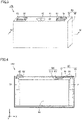
- Fig. 3 is a diagram showing battery cell 100 in battery pack 1.
- Fig. 4 is a cross sectional view when viewed in a direction of arrowed line IV-IV in Fig. 3 .
- battery cell 100 includes an exterior package 90, an electrode assembly 50, a positive electrode terminal 81, a negative electrode terminal 82, a positive electrode current collecting member 71, and a negative electrode current collecting member 72.
- Exterior package 90 has a prismatic shape (shape of flat profile rectangular parallelepiped). It should be noted that the prismatic shape is exemplary. Exterior package 90 may have any shape. Exterior package 90 may have, for example, a cylindrical shape or a pouch shape. Exterior package 90 may be composed of, for example, an A1 alloy. Exterior package 90 stores electrode assembly 50 and an electrolyte solution (not shown). Exterior package 90 may include, for example, a sealing plate 91 and an exterior container 92. Exterior container 92 is provided with an opening. Sealing plate 91 seals the opening of exterior container 92. For example, sealing plate 91 and exterior container 92 may be joined to each other by laser welding.
- Positive electrode terminal 81 and negative electrode terminal 82 are provided on sealing plate 91.
- Positive electrode terminal 81 is fixed to sealing plate 91 with an insulating member 61 being interposed therebetween, insulating member 61 being composed of a resin.
- Negative electrode terminal 82 is fixed to sealing plate 91 with an insulating member 62 being interposed therebetween, insulating member 62 being composed of a resin.
- Positive electrode terminal 81 is preferably composed of a metal, and is more preferably composed of aluminum or an aluminum alloy.
- Negative electrode terminal 82 is preferably composed of a metal, and is more preferably composed of copper or a copper alloy. Negative electrode terminal 82 may be configured to have: a region that is composed of copper or a copper alloy and that is disposed on the inner side of exterior package 90; and a region that is composed of aluminum or an aluminum alloy and that is disposed on the outer side of exterior package 90.
- Sealing plate 91 may be further provided with an injection opening 41 and a gas discharge valve 42.
- the electrolyte solution can be injected from injection opening 41 to inside of exterior package 90.
- Gas discharge valve 42 is fractured when pressure inside exterior package 90 becomes more than or equal to a threshold value.
- a current collecting portion is connected to electrode assembly 50.
- electrode assembly 50 is connected to positive electrode terminal 81 by positive electrode current collecting member 71.
- Positive electrode current collecting member 71 may be, for example, an Al plate or the like.
- Electrode assembly 50 is connected to negative electrode terminal 82 by negative electrode current collecting member 72.
- Negative electrode current collecting member 72 may be, for example, a Cu plate or the like.
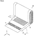
- Electrode assembly 50 which is a main body portion of battery cell 100, is disposed inside exterior package 90. Electrode assembly 50 is of winding type. Electrode assembly 50 includes a positive electrode 10, a separator 30, and a negative electrode 20. That is, battery cell 100 includes positive electrode 10, negative electrode 20, and the electrolyte solution. Each of positive electrode 10, separator 30, and negative electrode 20 is a sheet in the form of a strip. Electrode assembly 50 may include a plurality of separators 30. Electrode assembly 50 is formed by: layering positive electrode 10, separator 30, and negative electrode 20 in this order; and winding them in the form of a spiral.
- Electrode assembly 50 may be shaped to have a flat shape after the winding. It should be noted that the winding type is exemplary. Electrode assembly 50 may be, for example, of a stack type.
- Positive electrode 10 includes a positive electrode substrate 11 and a positive electrode active material layer 12.
- Positive electrode substrate 11 is an electrically conductive sheet. Positive electrode substrate 11 may be, for example, an Al alloy foil or the like. Positive electrode substrate 11 may have a thickness of, for example, 10 ⁇ m to 30 ⁇ m.
- Positive electrode active material layer 12 is disposed on a surface of positive electrode substrate 11. Positive electrode active material layer 12 may be disposed only on one surface of positive electrode substrate 11, for example. Positive electrode active material layer 12 may be disposed on each of the front and rear surfaces of positive electrode substrate 11, for example. Positive electrode substrate 11 may be exposed at one end portion in the width direction of positive electrode 10 (X axis direction in Fig. 5 ). Positive electrode current collecting member 71 can be joined to the exposed portion of positive electrode substrate 11.
- an intermediate layer may be formed between positive electrode active material layer 12 and positive electrode substrate 11.
- positive electrode active material layer 12 is regarded as being disposed on the surface of positive electrode substrate 11.
- the intermediate layer may be thinner than positive electrode active material layer 12.
- the intermediate layer may have a thickness of 0.1 ⁇ m to 10 ⁇ m, for example.
- the intermediate layer may include, for example, a conductive material, an insulating material, or the like.
- Positive electrode active material layer 12 may have a thickness of, for example, 10 ⁇ m to 200 ⁇ m. Positive electrode active material layer 12 may have a thickness of, for example, 50 ⁇ m to 150 ⁇ m. Positive electrode active material layer 12 may have a thickness of, for example, 50 ⁇ m to 100 ⁇ m.
- Positive electrode active material layer 12 includes a positive electrode active material.
- the positive electrode active material is a particle group.
- Positive electrode active material layer 12 may further include an additional component as long as the positive electrode active material is included.
- Positive electrode active material layer 12 may include, for example, a conductive material, a binder, or the like in addition to the positive electrode active material.
- the conductive material can include any component.
- the conductive material may include at least one selected from a group consisting of carbon black, graphite, vapor-grown carbon fiber (VGCF), carbon nanotube (CNT), and graphene flake.
- a blending amount of the conductive material may be, for example, 0.1 part by mass to 10 parts by mass with respect to 100 parts by mass of the positive electrode active material.
- the binder can include any component.
- the binder may include at least one selected from a group consisting of polyvinylidene difluoride (PVdF), poly(vinylidene fluoride-co-hexafluoropropylene) (PVdF-HFP), polytetrafluoroethylene (PTFE), and polyacrylic acid (PAA).
- PVdF polyvinylidene difluoride
- PVdF-HFP poly(vinylidene fluoride-co-hexafluoropropylene)
- PTFE polytetrafluoroethylene
- PAA polyacrylic acid
- a blending amount of the binder may be, for example, 0.1 part by mass to 10 parts by mass with respect to 100 parts by mass of the positive electrode active material.
- Positive electrode active material layer 12 can have a high density. Positive electrode active material layer 12 may have a density of 3.6 g/cm 3 to 3.9 g/cm 3 , for example. Positive electrode active material layer 12 may have a density of 3.65 g/cm 3 to 3.81 g/cm 3 , for example. Positive electrode active material layer 12 may have a density of 3.70 g/cm 3 to 3.81 g/cm 3 , for example. The density of the active material layer in the present specification represents an apparent density.
- Negative electrode 20 may include a negative electrode substrate 21 and a negative electrode active material layer 22, for example.
- Negative electrode substrate 21 is an electrically conductive sheet. Negative electrode substrate 21 may be, for example, a Cu alloy foil or the like. Negative electrode substrate 21 may have a thickness of, for example, 5 ⁇ m to 30 ⁇ m.
- Negative electrode active material layer 22 may be disposed on a surface of negative electrode substrate 21. Negative electrode active material layer 22 may be disposed only on one surface of negative electrode substrate 21, for example. Negative electrode active material layer 22 may be disposed on each of the front and rear surfaces of negative electrode substrate 21, for example. Negative electrode substrate 21 may be exposed at one end portion in the width direction of negative electrode 20 (X axis direction in Fig. 5 ). Negative electrode current collecting member 72 can be joined to the exposed portion of negative electrode substrate 21.
- Negative electrode active material layer 22 may have a thickness of, for example, 10 ⁇ m to 200 ⁇ m. Negative electrode active material layer 22 includes a negative electrode active material.
- the negative electrode active material may include any component.
- the negative electrode active material may include, for example, at least one selected from a group consisting of graphite, soft carbon, hard carbon, silicon, silicon oxide, a silicon-based alloy, tin, tin oxide, a tin-based alloy, and a lithium-titanium composite oxide.
- Negative electrode active material layer 22 may further include, for example, a binder or the like in addition to the negative electrode active material.
- negative electrode active material layer 22 may include: 95% to 99.5% of the negative electrode active material in mass fraction; and the remaining of the binder.
- the binder can include any component.
- the binder may include, for example, at least one selected from a group consisting of carboxymethyl cellulose (CMC) and styrenebutadiene rubber (SBR).
- separator 30 is disposed between positive electrode 10 and negative electrode 20. Separator 30 separates positive electrode 10 and negative electrode 20 from each other. Separator 30 may have a thickness of, for example, 10 ⁇ m to 30 ⁇ m.
- Separator 30 is a porous sheet.
- the electrolyte solution passes through separator 30.
- Separator 30 may have an air permeability of, for example, 200 s/100 mL to 400 s/100 mL.
- the "air permeability” represents “Air Resistance” defined in "JIS P 8117: 2009”. The air permeability is measured by the Gurley test method.
- Separator 30 is electrically insulative.
- Separator 30 may include, for example, a polyolefin-based resin or the like.
- Separator 30 may consist essentially of a polyolefin-based resin, for example.
- the polyolefin-based resin may include at least one selected from a group consisting of polyethylene (PE) and polypropylene (PP), for example.
- Separator 30 may have a single-layer structure, for example.
- Separator 30 may consist essentially of a PE layer, for example.
- Separator 30 may have a multilayer structure, for example.
- Separator 30 may be formed by layering a PP layer, a PE layer, and a PP layer in this order, for example.
- a heat-resistant layer or the like may be formed on the surface of separator 30, for example.
- the electrolyte solution includes a solvent and a supporting electrolyte.
- the solvent is aprotic.
- the solvent can include any component.
- the solvent may include, for example, at least one selected from a group consisting of ethylene carbonate (EC), propylene carbonate (PC), butylene carbonate (BC), dimethyl carbonate (DMC), ethyl methyl carbonate (EMC), diethyl carbonate (DEC), 1,2-dimethoxyethane (DME), methyl formate (MF), methyl acetate (MA), methyl propionate (MP), and ⁇ -butyrolactone (GBL).
- EC ethylene carbonate
- PC propylene carbonate
- BC butylene carbonate
- DMC dimethyl carbonate
- EMC ethyl methyl carbonate
- DEC diethyl carbonate
- DME 1,2-dimethoxyethane
- MF methyl formate
- MA methyl acetate
- MP methyl propionate
- the supporting electrolyte is dissolved in the solvent.
- the supporting electrolyte may include at least one selected from a group consisting of LiPF 6 , LiBF 4 , and LiN(FSO 2 ) 2 .
- the supporting electrolyte may have a molar concentration of, for example, 0.5 mol/L to 2.0 mol/L.
- the supporting electrolyte may have a molar concentration of, for example, 0.8 mol/L to 1.2 mol/L.
- the electrolyte solution may further include any additive in addition to the solvent and the supporting electrolyte.
- the electrolyte solution may include 0.01% to 5% of the additive in mass fraction.
- the additive may include, for example, at least one selected from a group consisting of vinylene carbonate (VC), lithium difluorophosphate (LiPO 2 F 2 ), lithium fluorosulfonate (FSO 3 Li), and lithium bis[oxalatoborate] (LiBOB).
- battery cell 100 further includes a detection unit 500. At least a portion of detection unit 500 is disposed inside exterior package 90. Detection unit 500 includes a circuit board 93 and an antenna portion 510.
- circuit board 93 is located on the inner surface side of sealing plate 91. Specifically, circuit board 93 is attached to the inner surface of sealing plate 91. Circuit board 93 has a circuit that detects a state of battery cell 100. In circuit board 93, an integrated circuit and an electronic component both formed on a semiconductor such as Si are mounted on a printed board having an insulating function. In the present embodiment, an antenna pattern is formed on the printed board.
- the state of battery cell 100 includes at least one of states of voltage, internal temperature, and internal pressure of battery cell 100. That is, detection unit 500 detects at least one of the states of the voltage of battery cell 100, the internal temperature of battery cell 100, and the internal pressure of battery cell 100.
- Antenna portion 510 is provided on circuit board 93. Antenna portion 510 performs wireless communication.
- antenna portion 510 is disposed inside exterior package 90. Even when antenna portion 510 is disposed inside exterior package 90, antenna portion 510 can transmit and receive an electric wave through insulating members 61, 62 disposed in the surroundings of positive electrode terminal 81 and negative electrode terminal 82.
- Antenna portion 510 may transmit and receive an electromagnetic wave when performing short-range wireless communication that conforms to, for example, ISO/IEC18092, ISO/IEC14443, or the like. It should be noted that antenna portion 510 may be drawn out to the outside of exterior package 90 through injection opening 41 or another hole formed in the exterior package.
- the short-range wireless communication employs Bluetooth to transmit a signal in a non-contact manner but is not limited to Bluetooth, and may employ communication in the NFC (Near Field Communication) standard.
- NFC Near Field Communication
- a communication device that conforms to the NFC standard is incorporated in a non-contact IC card such as a transportation card or an electronic money, or is incorporated in a small mobile device such as a mobile phone or a smartphone, and transmits a signal in the non-contact manner, for example.
- Antenna portion 510 of each of the plurality of battery cells 100 included in battery pack 1 is configured to perform wireless communication with a wireless communication unit that is electrically connected to a battery management system (BMS), which is a monitoring unit disposed outside battery cell 100.
- the battery management system (BMS) includes a cell management controller (CMC) and a battery management controller (BMC).
- the battery management system (BMS) is installed in a battery system, a vehicle, or the like. It should be noted that the battery management system (BMS) transmits and receives various types of signals to and from a battery ECU (Electronic Control Unit) through communication that conforms to a CAN (Controller Area Network) protocol.
- Detection unit 500 may be connected to a cloud available through a network by bidirectional communication of antenna portion 510.
- Fig. 6 is a circuit diagram showing electric connection between the battery cell and the detection unit. As shown in Fig. 6 , detection unit 500 is connected to a power feeding line L1.
- Power feeding line L1 is connected to each of positive electrode current collecting member 71 and negative electrode current collecting member 72. However, power feeding line L1 may be connected to only one of positive electrode current collecting member 71 and negative electrode current collecting member 72. Thus, detection unit 500 is electrically connected to the current collecting portion and is fed with power.
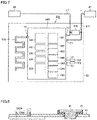
- Fig. 7 is a functional block diagram showing a specific example of the detection unit.
- detection unit 500 includes a microcomputer 590.
- Microcomputer 590 is mounted on circuit board 93.
- Microcomputer 590 includes a power supply control unit 591, a CPU 520, a clock control unit 592, a voltage sensor 540, an analog/digital converter 593, a temperature sensor 594, a peripheral function unit 595, a wireless communication function unit 596, a program memory 597, a RAM (Random Access Memory) 598, a nonvolatile memory 599, and a program rewriting control unit 580.
- Microcomputer 590 further includes two power supply terminals T1, an antenna terminal T2, and two sensor terminals T3.
- One power supply terminal T1 is electrically connected to positive electrode terminal 81 via power feeding line L1.
- Power feeding line L1 connected to positive electrode terminal 81 is provided with a fuse 571 to take a measure against overcurrent.
- the other power supply terminal T1 is electrically connected to negative electrode terminal 82 via power feeding line L1.
- a power supply input protection component 570 is connected between power feeding line L1 connected to positive electrode terminal 81 and power feeding line L1 connected to negative electrode terminal 82.
- Antenna terminal T2 is connected to antenna portion 510.
- Antenna portion 510 is, for example, a pattern antenna formed on circuit board 93 to have a meandering shape. It should be noted that the shape and type of antenna portion 510 are appropriately set.
- One sensor terminal T3 is connected to a pressure sensor 550.
- Pressure sensor 550 is disposed inside battery cell 100 to measure an internal pressure of battery cell 100.
- the other sensor terminal T3 is connected to a voltage sensor 560.
- Voltage sensor 560 is disposed inside battery cell 100 and is electrically connected to exterior container 92 to measure a potential of exterior container 92.
- power supply control unit 591 From power fed from battery cell 100, power supply control unit 591 generates power for operating microcomputer 590. Further, power supply control unit 591 controls an operation mode of microcomputer 590. Further, power supply control unit 591 can generate a reset signal.
- Clock control unit 592 generates an operation clock and a communication clock through internal oscillation, and controls the operation clock and the communication clock.
- Voltage sensor 540 measures the voltage of battery cell 100 by detecting a potential difference between one power supply terminal T1 and the other power supply terminal T1. It should be noted that voltage sensor 540 converts a detected value of the potential difference, which is represented by an analog signal, into a parameter value of the voltage, which is represented by a digital signal, and outputs the parameter value.
- Analog/digital converter 593 converts the detected value of the analog signal input from each of pressure sensor 550 and voltage sensor 560 into the parameter value that is represented by the digital signal, and outputs the parameter value.
- Temperature sensor 594 is provided in microcomputer 590, and measures the internal temperature of battery cell 100.
- Peripheral function unit 595 performs a peripheral function of microcomputer 590 required for a program operation such as a timer.
- Wireless communication function unit 596 has an RF (Radio Frequency) transceiver circuit that is capable of transmitting and receiving.
- Program memory 597 which serves as a storage unit, is a rewritable nonvolatile memory that stores a program for operating microcomputer 590.
- RAM 598 is a work memory for temporarily storing a program and data.
- Nonvolatile memory 599 stores specific data, measurement history data, and the like for battery cell 100.
- Program rewriting control unit 580 performs, via wireless communication, rewriting or debugging of a program stored in program memory 597.
- Microcomputer 590 can detect a state of battery cell 100 and can control a built-in function based on an instruction signal transmitted from the wireless communication unit electrically connected to the battery management system (BMS).
- BMS battery management system
- the state of battery cell 100 to be detected includes: the voltage of battery cell 100 detected by voltage sensor 540; the potential of exterior container 92 detected by voltage sensor 560; the internal temperature of battery cell 100 detected by temperature sensor 594; and the internal pressure of battery cell 100 detected by pressure sensor 550.
- microcomputer 590 performing various types of processing, the state information of battery cell 100 is subjected to A/D conversion and various types of signal processing, and is transmitted to the battery management system (BMS). Further, various types of measurement values and measurement histories are stored in nonvolatile memory 599.
- the battery management system transmits an instruction signal for performing cell balancing to equalize the voltages of battery cells 100.
- an instruction signal is transmitted to a battery cell 100 having a high voltage value so as to operate a microcomputer 590 of battery cell 100 or so as to cause microcomputer 590 of battery cell 100 to perform wireless communication. Since microcomputer 590 of battery cell 100 having received the instruction signal is operated or performs wireless communication to consume power, the voltages of the plurality of battery cells 100 in battery pack 1 are equalized.
- microcomputer 590 itself or wireless communication function unit 596 serves as a cell balancing unit that equalizes the voltage of each power storage cell.
- detection unit 500 is disposed inside exterior package 90, the occupied space of battery cell 100 including detection unit 500 that performs wireless communication can be suppressed from being large.
- detection unit 500 since detection unit 500 is electrically connected to the current collecting portion and is fed with power, it is not necessary to additionally dispose a power supply for feeding power to detection unit 500, with the result that the occupied space of battery cell 100 including detection unit 500 that performs wireless communication can be suppressed from being large.
- the voltage of battery cell 100 can be measured with high precision as compared with the case where the voltage of battery cell 100 is measured via a bus bar that connects battery cells 100.
- the internal pressure of battery cell 100 can be measured with high precision.
- circuit board 94 may be subjected to insulating treatment by coating or potting with a resin. With this insulating treatment, internal short circuit of battery cell 100 due to a metal piece or the like can be prevented.
- Fig. 8 is a partial cross sectional view showing a periphery of an antenna portion of a battery cell according to a first modification of the first embodiment.
- an antenna portion 510a extends to the outside of exterior package 90 through sealing plate 91.
- an insulating sealing member (not shown) seals between antenna portion 510a and sealing plate 91.
- Fig. 9 is an exploded perspective view showing configurations of a detection unit and an exterior package of a battery cell according to a second modification of the first embodiment.
- Fig. 10 is a partial cross sectional view showing the configuration of the detection unit of the battery cell according to the second modification of the first embodiment.
- a detection unit 500B includes: an insulating circuit board 93B having a circuit that detects a state of the battery cell; and an antenna portion 510 provided on insulating circuit board 93B. Insulating circuit board 93B seals the opening of exterior container 92. Antenna portion 510 is located outside the exterior package.
- Insulating circuit board 93B is composed of, for example, an insulating resin such as a glass epoxy resin.
- each of positive electrode terminal 81 and negative electrode terminal 82 is directly fixed to the sealing plate constituted of insulating circuit board 93B.
- Insulating circuit board 93B and exterior container 92 are hermetically joined to each other by a joining material (not shown).
- antenna portion 510 is disposed outside the exterior package with insulating circuit board 93B being disposed inside the exterior package, the wireless communication characteristics of detection unit 500B can be improved while suppressing the occupied space of the battery cell from being large. Further, since insulating members 61, 62 are not required, the number of components can be reduced.
- battery cell according to a second embodiment will be described with reference to figures. Because the battery cell according to the second embodiment is different from battery cell 100 according to the first embodiment in that the exterior package is of the pouch type and the electrode assembly serving as the main body portion is of the stack type, the same configurations as those in battery cell 100 according to the first embodiment will not be described repeatedly.
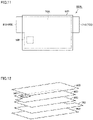
- Fig. 11 is a plan view showing an external appearance of the battery cell according to the second embodiment.
- Fig. 12 is an exploded perspective view showing a configuration of the battery cell according to the second embodiment.
- a battery cell 100A according to the second embodiment includes an exterior package 600, an electrode assembly 50A, and detection unit 500.
- Exterior package 600 is constituted of two shrink films adhered to each other.
- Each of the shrink films is, for example, an aluminum laminate film in which an aluminum foil and a resin film are layered.
- Electrode assembly 50A is disposed inside exterior package 600.
- An electrolyte solution (not shown) is provided inside exterior package 600.
- Electrode assembly 50A is constructed by layering a positive electrode 700, a separator 900, and a negative electrode 800 in this order.
- a positive electrode current collecting portion 710 which is a portion of positive electrode 700
- a negative electrode current collecting portion 810 which is a portion of negative electrode 800, is drawn out to the outside of exterior package 600.
- separator 900 is interposed between positive electrode 700 and negative electrode 800.
- Separator 900 separates positive electrode 700 and negative electrode 800 from each other.
- Separator 900 is a porous sheet.
- the electrolyte solution passes through separator 900.
- Separator 900 is electrically insulative.
- Detection unit 500 is disposed on negative electrode 800 inside exterior package 600. Detection unit 500 is electrically connected to negative electrode 800 and is fed with power.
- an opening may be provided in the aluminum foil located at a portion of exterior package 600 covering the antenna portion, or only the tip of the antenna portion may be located outside exterior package 600. It should be noted that the antenna portion may be drawn out to the outside of exterior package 600 through a hole formed in exterior package 600.
- battery cell 100A since detection unit 500 is disposed inside exterior package 600, the occupied space of battery cell 100A including detection unit 500 that performs wireless communication can be suppressed from being large. Further, since exterior package 600 of the pouch type is smaller than the exterior package having the exterior container, the occupied space of battery cell 100A can be effectively suppressed from being large.
- Fig. 13 is a plan view showing an external appearance of the battery cell according to the modification of the second embodiment.
- detection unit 500 of a battery cell 100B according to the modification of the second embodiment is disposed on negative electrode current collecting portion 810.
- Detection unit 500 is electrically connected to negative electrode current collecting portion 810 and is fed with power.
- detection unit 500 is electrically connected to the current collecting portion and is fed with power, it is not necessary to additionally dispose a power supply for feeding power to detection unit 500, with the result that the occupied space of battery cell 100B including detection unit 500 that performs wireless communication can be suppressed from being large. Since the antenna portion is disposed outside exterior package 600, the wireless communication characteristics of detection unit 500 can be improved.
Landscapes
- Engineering & Computer Science (AREA)
- Chemical & Material Sciences (AREA)
- Chemical Kinetics & Catalysis (AREA)
- Electrochemistry (AREA)
- General Chemical & Material Sciences (AREA)
- Manufacturing & Machinery (AREA)
- Microelectronics & Electronic Packaging (AREA)
- Battery Mounting, Suspending (AREA)
- Secondary Cells (AREA)
- Charge And Discharge Circuits For Batteries Or The Like (AREA)
- Sealing Battery Cases Or Jackets (AREA)
- Hybrid Cells (AREA)
Applications Claiming Priority (1)
| Application Number | Priority Date | Filing Date | Title |
|---|---|---|---|
| JP2021039304A JP7649665B2 (ja) | 2021-03-11 | 2021-03-11 | 蓄電セル |
Publications (2)
| Publication Number | Publication Date |
|---|---|
| EP4057421A2 true EP4057421A2 (de) | 2022-09-14 |
| EP4057421A3 EP4057421A3 (de) | 2023-01-04 |
Family
ID=80445527
Family Applications (1)
| Application Number | Title | Priority Date | Filing Date |
|---|---|---|---|
| EP22155556.8A Pending EP4057421A3 (de) | 2021-03-11 | 2022-02-08 | Energiespeicherzelle |
Country Status (5)
| Country | Link |
|---|---|
| US (1) | US20220294041A1 (de) |
| EP (1) | EP4057421A3 (de) |
| JP (2) | JP7649665B2 (de) |
| KR (1) | KR102824988B1 (de) |
| CN (1) | CN115084692B (de) |
Cited By (3)
| Publication number | Priority date | Publication date | Assignee | Title |
|---|---|---|---|---|
| EP4266451A1 (de) | 2022-04-22 | 2023-10-25 | Dukosi Limited | Verbesserte elektrische batterieanordnung |
| EP4283821A1 (de) * | 2022-05-27 | 2023-11-29 | Dukosi Limited | Vorrichtung und entsprechendes verfahren zum zellenausgleich in einem elektrischen batteriesystem |
| EP4586363A1 (de) * | 2024-01-12 | 2025-07-16 | Samsung SDI Co., Ltd. | Wiederaufladbares batteriemodul |
Families Citing this family (2)
| Publication number | Priority date | Publication date | Assignee | Title |
|---|---|---|---|---|
| JP7649665B2 (ja) * | 2021-03-11 | 2025-03-21 | プライムプラネットエナジー&ソリューションズ株式会社 | 蓄電セル |
| WO2025193009A1 (ko) * | 2024-03-14 | 2025-09-18 | 엘지이노텍 주식회사 | 배터리 관리 장치 |
Citations (10)
| Publication number | Priority date | Publication date | Assignee | Title |
|---|---|---|---|---|
| EP2600443A2 (de) | 2011-11-16 | 2013-06-05 | Nxp B.V. | Integrierte Batterieverwaltungsvorrichtung |
| EP2642574A1 (de) | 2010-11-19 | 2013-09-25 | Sony Corporation | Sekundärbatteriezelle, batteriepack und stromverbrauchseinheit |
| EP3537562A1 (de) | 2017-07-06 | 2019-09-11 | LG Chem, Ltd. | Drahtloses batterieverwaltungssystem und batteriepack damit |
| EP3536541A1 (de) | 2017-07-19 | 2019-09-11 | LG Chem, Ltd. | Drahtloses batterieverwaltungssystem und batteriepack damit |
| JP2020027767A (ja) | 2018-08-14 | 2020-02-20 | 矢崎総業株式会社 | バッテリ監視装置 |
| US20200099111A1 (en) | 2018-09-25 | 2020-03-26 | Denso Corporation | Battery monitoring system |
| US20200142004A1 (en) | 2018-11-05 | 2020-05-07 | Denso Corporation | Battery monitoring apparatus |
| US20200207219A1 (en) | 2018-03-22 | 2020-07-02 | Tae Technologies, Inc. | Systems and methods for power management and control |
| JP2021039304A (ja) | 2019-09-05 | 2021-03-11 | キヤノン株式会社 | 光学系およびそれを有する撮像装置 |
| EP3945657A1 (de) | 2020-07-31 | 2022-02-02 | Volvo Car Corporation | Intelligente batteriezelle mit integrierter überwachung und schaltern |
Family Cites Families (22)
| Publication number | Priority date | Publication date | Assignee | Title |
|---|---|---|---|---|
| JP5466586B2 (ja) | 2009-10-05 | 2014-04-09 | プライムアースEvエナジー株式会社 | 組電池の管理装置 |
| JP2011119949A (ja) | 2009-12-02 | 2011-06-16 | Mitsumi Electric Co Ltd | カードデバイス |
| JP5126251B2 (ja) | 2010-03-01 | 2013-01-23 | 株式会社デンソー | 電池電圧監視装置 |
| JP5453184B2 (ja) | 2010-06-28 | 2014-03-26 | 日立ビークルエナジー株式会社 | 電池制御回路 |
| EP3699617B1 (de) * | 2011-10-07 | 2024-02-07 | Hitachi Astemo, Ltd. | Batterieüberwachungsgerät und batterieüberwachungssystem |
| WO2013051157A1 (ja) | 2011-10-07 | 2013-04-11 | 日立ビークルエナジー株式会社 | 電池監視システム、上位コントローラ、電池監視装置 |
| DE102011088440A1 (de) * | 2011-12-13 | 2013-06-13 | Fraunhofer-Gesellschaft zur Förderung der angewandten Forschung e.V. | Energiespeicherzelle, Energiespeicherzellenmodul und Trägersubstrat |
| DE102011088530A1 (de) * | 2011-12-14 | 2013-06-20 | Robert Bosch Gmbh | Vorrichtung und Verfahren zum Übertragen einer Information aus einer Batteriezelle und Batteriezelle |
| JP5939871B2 (ja) | 2012-04-19 | 2016-06-22 | 株式会社日立製作所 | 二次電池、二次電池システム、それらの制御方法 |
| JP2013236492A (ja) | 2012-05-09 | 2013-11-21 | Panasonic Corp | 電池モジュール、及び電池管理システム |
| US9419457B2 (en) * | 2012-09-04 | 2016-08-16 | Google Technology Holdings LLC | Method and device with enhanced battery capacity savings |
| JP2014127386A (ja) | 2012-12-27 | 2014-07-07 | Sumitomo Electric Ind Ltd | 電池装置、組電池システム及び電気推進車両 |
| JP2015162275A (ja) | 2014-02-26 | 2015-09-07 | 株式会社Gsユアサ | 蓄電素子 |
| US9911951B2 (en) * | 2014-09-30 | 2018-03-06 | Johnson Controls Technology Company | Battery module compressed cell assembly |
| JP2016149311A (ja) * | 2015-02-13 | 2016-08-18 | ソニー株式会社 | 二次電池、電池パック、電動車両、電力貯蔵システム、電動工具および電子機器 |
| JP6916983B2 (ja) * | 2016-11-01 | 2021-08-11 | 株式会社オートネットワーク技術研究所 | 車両用のバッテリ監視システム |
| US10823786B2 (en) * | 2017-07-28 | 2020-11-03 | Northstar Battery Company, Llc | Battery with internal monitoring system |
| CN108550937B (zh) * | 2018-05-03 | 2021-07-06 | 深圳市熙锦科技发展有限公司 | 内置无线充电线圈的充电电池 |
| CN112103576B (zh) * | 2020-09-21 | 2021-06-22 | 北京理工大学 | 一种智能电池 |
| CN112201866A (zh) * | 2020-09-29 | 2021-01-08 | 欣旺达电动汽车电池有限公司 | 智能电芯、电池系统及电动车 |
| KR20220085590A (ko) * | 2020-12-15 | 2022-06-22 | 삼성전자주식회사 | 파우치형 플렉서블 배터리 |
| JP7649665B2 (ja) * | 2021-03-11 | 2025-03-21 | プライムプラネットエナジー&ソリューションズ株式会社 | 蓄電セル |
-
2021
- 2021-03-11 JP JP2021039304A patent/JP7649665B2/ja active Active
-
2022
- 2022-02-08 EP EP22155556.8A patent/EP4057421A3/de active Pending
- 2022-02-25 US US17/681,258 patent/US20220294041A1/en active Pending
- 2022-03-04 KR KR1020220028092A patent/KR102824988B1/ko active Active
- 2022-03-10 CN CN202210228328.3A patent/CN115084692B/zh active Active
-
2024
- 2024-07-29 JP JP2024122368A patent/JP7791259B2/ja active Active
Patent Citations (10)
| Publication number | Priority date | Publication date | Assignee | Title |
|---|---|---|---|---|
| EP2642574A1 (de) | 2010-11-19 | 2013-09-25 | Sony Corporation | Sekundärbatteriezelle, batteriepack und stromverbrauchseinheit |
| EP2600443A2 (de) | 2011-11-16 | 2013-06-05 | Nxp B.V. | Integrierte Batterieverwaltungsvorrichtung |
| EP3537562A1 (de) | 2017-07-06 | 2019-09-11 | LG Chem, Ltd. | Drahtloses batterieverwaltungssystem und batteriepack damit |
| EP3536541A1 (de) | 2017-07-19 | 2019-09-11 | LG Chem, Ltd. | Drahtloses batterieverwaltungssystem und batteriepack damit |
| US20200207219A1 (en) | 2018-03-22 | 2020-07-02 | Tae Technologies, Inc. | Systems and methods for power management and control |
| JP2020027767A (ja) | 2018-08-14 | 2020-02-20 | 矢崎総業株式会社 | バッテリ監視装置 |
| US20200099111A1 (en) | 2018-09-25 | 2020-03-26 | Denso Corporation | Battery monitoring system |
| US20200142004A1 (en) | 2018-11-05 | 2020-05-07 | Denso Corporation | Battery monitoring apparatus |
| JP2021039304A (ja) | 2019-09-05 | 2021-03-11 | キヤノン株式会社 | 光学系およびそれを有する撮像装置 |
| EP3945657A1 (de) | 2020-07-31 | 2022-02-02 | Volvo Car Corporation | Intelligente batteriezelle mit integrierter überwachung und schaltern |
Cited By (3)
| Publication number | Priority date | Publication date | Assignee | Title |
|---|---|---|---|---|
| EP4266451A1 (de) | 2022-04-22 | 2023-10-25 | Dukosi Limited | Verbesserte elektrische batterieanordnung |
| EP4283821A1 (de) * | 2022-05-27 | 2023-11-29 | Dukosi Limited | Vorrichtung und entsprechendes verfahren zum zellenausgleich in einem elektrischen batteriesystem |
| EP4586363A1 (de) * | 2024-01-12 | 2025-07-16 | Samsung SDI Co., Ltd. | Wiederaufladbares batteriemodul |
Also Published As
| Publication number | Publication date |
|---|---|
| JP7791259B2 (ja) | 2025-12-23 |
| KR102824988B1 (ko) | 2025-06-26 |
| KR20220127751A (ko) | 2022-09-20 |
| JP2024147813A (ja) | 2024-10-16 |
| CN115084692B (zh) | 2026-04-21 |
| US20220294041A1 (en) | 2022-09-15 |
| JP2022139076A (ja) | 2022-09-26 |
| CN115084692A (zh) | 2022-09-20 |
| JP7649665B2 (ja) | 2025-03-21 |
| EP4057421A3 (de) | 2023-01-04 |
Similar Documents
| Publication | Publication Date | Title |
|---|---|---|
| EP4057421A2 (de) | Energiespeicherzelle | |
| US8859124B2 (en) | Integrated circuit and battery pack using the same | |
| KR102032356B1 (ko) | 전지모듈용 전압 센싱 블록 | |
| US7618724B2 (en) | Electrochemical device comprising electrode lead having protection device | |
| JP6961103B2 (ja) | 電池及び電池パック | |
| US20150037658A1 (en) | Stack type battery | |
| CN104205422B (zh) | 电池以及电池包 | |
| EP3118913B1 (de) | Batterie mit nichtwässrigem elektrolyt und batteriepack | |
| US20140127541A1 (en) | Cylindrical secondary battery and battery system | |
| KR102264734B1 (ko) | 비수성 전해액 및 이를 포함하는 리튬 이차전지 | |
| US12374764B2 (en) | Secondary battery | |
| US20230024426A1 (en) | Secondary battery | |
| US20220352601A1 (en) | Secondary battery | |
| JP7556898B2 (ja) | 二次電池 | |
| KR101839405B1 (ko) | 메모리 칩의 파손 여부를 감지하는 검출 소자를 포함하는 보호회로 및 이를 포함하는 이차전지 팩 | |
| US20240047829A1 (en) | Secondary battery | |
| US11296359B2 (en) | Non-aqueous electrolyte solution and lithium secondary battery including the same | |
| KR20190046171A (ko) | 전지모듈 | |
| JP6257493B2 (ja) | 蓄電素子 | |
| KR20170012986A (ko) | 방열 보조부가 형성되어 있는 팩 케이스를 포함하고 있는 전지팩 | |
| KR102092114B1 (ko) | 전지셀들이 직교 배향에 의해 일체로 형성되어 있는 구조의 전지팩 | |
| JPH11233076A (ja) | 組電池 | |
| US20250391925A1 (en) | Secondary battery | |
| US20250392025A1 (en) | Secondary battery | |
| KR20130131736A (ko) | 안전성이 향상된 전극 조립체 및 이를 포함하는 이차전지 |
Legal Events
| Date | Code | Title | Description |
|---|---|---|---|
| PUAI | Public reference made under article 153(3) epc to a published international application that has entered the european phase |
Free format text: ORIGINAL CODE: 0009012 |
|
| STAA | Information on the status of an ep patent application or granted ep patent |
Free format text: STATUS: REQUEST FOR EXAMINATION WAS MADE |
|
| 17P | Request for examination filed |
Effective date: 20220208 |
|
| AK | Designated contracting states |
Kind code of ref document: A2 Designated state(s): AL AT BE BG CH CY CZ DE DK EE ES FI FR GB GR HR HU IE IS IT LI LT LU LV MC MK MT NL NO PL PT RO RS SE SI SK SM TR |
|
| RIC1 | Information provided on ipc code assigned before grant |
Ipc: H01M 10/42 20060101ALI20220830BHEP Ipc: H01M 10/48 20060101AFI20220830BHEP |
|
| PUAL | Search report despatched |
Free format text: ORIGINAL CODE: 0009013 |
|
| AK | Designated contracting states |
Kind code of ref document: A3 Designated state(s): AL AT BE BG CH CY CZ DE DK EE ES FI FR GB GR HR HU IE IS IT LI LT LU LV MC MK MT NL NO PL PT RO RS SE SI SK SM TR |
|
| RIC1 | Information provided on ipc code assigned before grant |
Ipc: H01M 10/42 20060101ALI20221129BHEP Ipc: H01M 10/48 20060101AFI20221129BHEP |
|
| TPAC | Observations filed by third parties |
Free format text: ORIGINAL CODE: EPIDOSNTIPA |
|
| TPAC | Observations filed by third parties |
Free format text: ORIGINAL CODE: EPIDOSNTIPA |
|
| STAA | Information on the status of an ep patent application or granted ep patent |
Free format text: STATUS: EXAMINATION IS IN PROGRESS |
|
| 17Q | First examination report despatched |
Effective date: 20250130 |