EP3945874B1 - Appareil et procédé de formation d'une tige tubulaire continu à partir d'un matériau d'étoupe continu - Google Patents
Appareil et procédé de formation d'une tige tubulaire continu à partir d'un matériau d'étoupe continu Download PDFInfo
- Publication number
- EP3945874B1 EP3945874B1 EP20711980.1A EP20711980A EP3945874B1 EP 3945874 B1 EP3945874 B1 EP 3945874B1 EP 20711980 A EP20711980 A EP 20711980A EP 3945874 B1 EP3945874 B1 EP 3945874B1
- Authority
- EP
- European Patent Office
- Prior art keywords
- fluid
- pressure
- continuous
- tow material
- forming apparatus
- Prior art date
- Legal status (The legal status is an assumption and is not a legal conclusion. Google has not performed a legal analysis and makes no representation as to the accuracy of the status listed.)
- Active
Links
Images


Classifications
-
- A—HUMAN NECESSITIES
- A24—TOBACCO; CIGARS; CIGARETTES; SIMULATED SMOKING DEVICES; SMOKERS' REQUISITES
- A24D—CIGARS; CIGARETTES; TOBACCO SMOKE FILTERS; MOUTHPIECES OF CIGARS OR CIGARETTES; MANUFACTURE OF TOBACCO SMOKE FILTERS OR MOUTHPIECES
- A24D3/00—Tobacco smoke filters, e.g. filter tips or filtering inserts; Filters specially adapted for simulated smoking devices; Mouthpieces of cigars or cigarettes
- A24D3/02—Manufacture of tobacco smoke filters
- A24D3/0229—Filter rod forming processes
-
- A—HUMAN NECESSITIES
- A24—TOBACCO; CIGARS; CIGARETTES; SIMULATED SMOKING DEVICES; SMOKERS' REQUISITES
- A24D—CIGARS; CIGARETTES; TOBACCO SMOKE FILTERS; MOUTHPIECES OF CIGARS OR CIGARETTES; MANUFACTURE OF TOBACCO SMOKE FILTERS OR MOUTHPIECES
- A24D3/00—Tobacco smoke filters, e.g. filter tips or filtering inserts; Filters specially adapted for simulated smoking devices; Mouthpieces of cigars or cigarettes
- A24D3/02—Manufacture of tobacco smoke filters
- A24D3/025—Final operations, i.e. after the filter rod forming process
- A24D3/0254—Cutting means
-
- A—HUMAN NECESSITIES
- A24—TOBACCO; CIGARS; CIGARETTES; SIMULATED SMOKING DEVICES; SMOKERS' REQUISITES
- A24D—CIGARS; CIGARETTES; TOBACCO SMOKE FILTERS; MOUTHPIECES OF CIGARS OR CIGARETTES; MANUFACTURE OF TOBACCO SMOKE FILTERS OR MOUTHPIECES
- A24D3/00—Tobacco smoke filters, e.g. filter tips or filtering inserts; Filters specially adapted for simulated smoking devices; Mouthpieces of cigars or cigarettes
- A24D3/02—Manufacture of tobacco smoke filters
- A24D3/0275—Manufacture of tobacco smoke filters for filters with special features
- A24D3/0291—Manufacture of tobacco smoke filters for filters with special features for hollow tipped filters, e.g. recess filters
-
- A—HUMAN NECESSITIES
- A24—TOBACCO; CIGARS; CIGARETTES; SIMULATED SMOKING DEVICES; SMOKERS' REQUISITES
- A24D—CIGARS; CIGARETTES; TOBACCO SMOKE FILTERS; MOUTHPIECES OF CIGARS OR CIGARETTES; MANUFACTURE OF TOBACCO SMOKE FILTERS OR MOUTHPIECES
- A24D3/00—Tobacco smoke filters, e.g. filter tips or filtering inserts; Filters specially adapted for simulated smoking devices; Mouthpieces of cigars or cigarettes
- A24D3/06—Use of materials for tobacco smoke filters
- A24D3/08—Use of materials for tobacco smoke filters of organic materials as carrier or major constituent
- A24D3/10—Use of materials for tobacco smoke filters of organic materials as carrier or major constituent of cellulose or cellulose derivatives
-
- B—PERFORMING OPERATIONS; TRANSPORTING
- B29—WORKING OF PLASTICS; WORKING OF SUBSTANCES IN A PLASTIC STATE IN GENERAL
- B29C—SHAPING OR JOINING OF PLASTICS; SHAPING OF MATERIAL IN A PLASTIC STATE, NOT OTHERWISE PROVIDED FOR; AFTER-TREATMENT OF THE SHAPED PRODUCTS, e.g. REPAIRING
- B29C33/00—Moulds or cores; Details thereof or accessories therefor
- B29C33/02—Moulds or cores; Details thereof or accessories therefor with incorporated heating or cooling means
- B29C33/04—Moulds or cores; Details thereof or accessories therefor with incorporated heating or cooling means using liquids, gas or steam
- B29C33/048—Moulds or cores; Details thereof or accessories therefor with incorporated heating or cooling means using liquids, gas or steam using steam
-
- B—PERFORMING OPERATIONS; TRANSPORTING
- B29—WORKING OF PLASTICS; WORKING OF SUBSTANCES IN A PLASTIC STATE IN GENERAL
- B29C—SHAPING OR JOINING OF PLASTICS; SHAPING OF MATERIAL IN A PLASTIC STATE, NOT OTHERWISE PROVIDED FOR; AFTER-TREATMENT OF THE SHAPED PRODUCTS, e.g. REPAIRING
- B29C35/00—Heating, cooling or curing, e.g. crosslinking or vulcanising; Apparatus therefor
- B29C35/02—Heating or curing, e.g. crosslinking or vulcanizing during moulding, e.g. in a mould
- B29C35/04—Heating or curing, e.g. crosslinking or vulcanizing during moulding, e.g. in a mould using liquids, gas or steam
- B29C35/049—Heating or curing, e.g. crosslinking or vulcanizing during moulding, e.g. in a mould using liquids, gas or steam using steam or damp
-
- B—PERFORMING OPERATIONS; TRANSPORTING
- B29—WORKING OF PLASTICS; WORKING OF SUBSTANCES IN A PLASTIC STATE IN GENERAL
- B29C—SHAPING OR JOINING OF PLASTICS; SHAPING OF MATERIAL IN A PLASTIC STATE, NOT OTHERWISE PROVIDED FOR; AFTER-TREATMENT OF THE SHAPED PRODUCTS, e.g. REPAIRING
- B29C70/00—Shaping composites, i.e. plastics material comprising reinforcements, fillers or preformed parts, e.g. inserts
- B29C70/04—Shaping composites, i.e. plastics material comprising reinforcements, fillers or preformed parts, e.g. inserts comprising reinforcements only, e.g. self-reinforcing plastics
- B29C70/28—Shaping operations therefor
- B29C70/30—Shaping by lay-up, i.e. applying fibres, tape or broadsheet on a mould, former or core; Shaping by spray-up, i.e. spraying of fibres on a mould, former or core
-
- B—PERFORMING OPERATIONS; TRANSPORTING
- B29—WORKING OF PLASTICS; WORKING OF SUBSTANCES IN A PLASTIC STATE IN GENERAL
- B29C—SHAPING OR JOINING OF PLASTICS; SHAPING OF MATERIAL IN A PLASTIC STATE, NOT OTHERWISE PROVIDED FOR; AFTER-TREATMENT OF THE SHAPED PRODUCTS, e.g. REPAIRING
- B29C70/00—Shaping composites, i.e. plastics material comprising reinforcements, fillers or preformed parts, e.g. inserts
- B29C70/04—Shaping composites, i.e. plastics material comprising reinforcements, fillers or preformed parts, e.g. inserts comprising reinforcements only, e.g. self-reinforcing plastics
- B29C70/28—Shaping operations therefor
- B29C70/40—Shaping or impregnating by compression not applied
- B29C70/42—Shaping or impregnating by compression not applied for producing articles of definite length, i.e. discrete articles
- B29C70/44—Shaping or impregnating by compression not applied for producing articles of definite length, i.e. discrete articles using isostatic pressure, e.g. pressure difference-moulding, vacuum bag-moulding, autoclave-moulding or expanding rubber-moulding
- B29C70/446—Moulding structures having an axis of symmetry or at least one channel, e.g. tubular structures, frames
-
- A—HUMAN NECESSITIES
- A24—TOBACCO; CIGARS; CIGARETTES; SIMULATED SMOKING DEVICES; SMOKERS' REQUISITES
- A24D—CIGARS; CIGARETTES; TOBACCO SMOKE FILTERS; MOUTHPIECES OF CIGARS OR CIGARETTES; MANUFACTURE OF TOBACCO SMOKE FILTERS OR MOUTHPIECES
- A24D3/00—Tobacco smoke filters, e.g. filter tips or filtering inserts; Filters specially adapted for simulated smoking devices; Mouthpieces of cigars or cigarettes
- A24D3/02—Manufacture of tobacco smoke filters
- A24D3/0204—Preliminary operations before the filter rod forming process, e.g. crimping, blooming
- A24D3/0212—Applying additives to filter materials
- A24D3/022—Applying additives to filter materials with liquid additives, e.g. application of plasticisers
-
- A—HUMAN NECESSITIES
- A24—TOBACCO; CIGARS; CIGARETTES; SIMULATED SMOKING DEVICES; SMOKERS' REQUISITES
- A24D—CIGARS; CIGARETTES; TOBACCO SMOKE FILTERS; MOUTHPIECES OF CIGARS OR CIGARETTES; MANUFACTURE OF TOBACCO SMOKE FILTERS OR MOUTHPIECES
- A24D3/00—Tobacco smoke filters, e.g. filter tips or filtering inserts; Filters specially adapted for simulated smoking devices; Mouthpieces of cigars or cigarettes
- A24D3/02—Manufacture of tobacco smoke filters
- A24D3/0229—Filter rod forming processes
- A24D3/0233—Filter rod forming processes by means of a garniture
-
- A—HUMAN NECESSITIES
- A24—TOBACCO; CIGARS; CIGARETTES; SIMULATED SMOKING DEVICES; SMOKERS' REQUISITES
- A24D—CIGARS; CIGARETTES; TOBACCO SMOKE FILTERS; MOUTHPIECES OF CIGARS OR CIGARETTES; MANUFACTURE OF TOBACCO SMOKE FILTERS OR MOUTHPIECES
- A24D3/00—Tobacco smoke filters, e.g. filter tips or filtering inserts; Filters specially adapted for simulated smoking devices; Mouthpieces of cigars or cigarettes
- A24D3/02—Manufacture of tobacco smoke filters
- A24D3/0295—Process control means
-
- B—PERFORMING OPERATIONS; TRANSPORTING
- B29—WORKING OF PLASTICS; WORKING OF SUBSTANCES IN A PLASTIC STATE IN GENERAL
- B29C—SHAPING OR JOINING OF PLASTICS; SHAPING OF MATERIAL IN A PLASTIC STATE, NOT OTHERWISE PROVIDED FOR; AFTER-TREATMENT OF THE SHAPED PRODUCTS, e.g. REPAIRING
- B29C2793/00—Shaping techniques involving a cutting or machining operation
- B29C2793/0027—Cutting off
-
- B—PERFORMING OPERATIONS; TRANSPORTING
- B29—WORKING OF PLASTICS; WORKING OF SUBSTANCES IN A PLASTIC STATE IN GENERAL
- B29C—SHAPING OR JOINING OF PLASTICS; SHAPING OF MATERIAL IN A PLASTIC STATE, NOT OTHERWISE PROVIDED FOR; AFTER-TREATMENT OF THE SHAPED PRODUCTS, e.g. REPAIRING
- B29C2793/00—Shaping techniques involving a cutting or machining operation
- B29C2793/009—Shaping techniques involving a cutting or machining operation after shaping
-
- B—PERFORMING OPERATIONS; TRANSPORTING
- B29—WORKING OF PLASTICS; WORKING OF SUBSTANCES IN A PLASTIC STATE IN GENERAL
- B29K—INDEXING SCHEME ASSOCIATED WITH SUBCLASSES B29B, B29C OR B29D, RELATING TO MOULDING MATERIALS OR TO MATERIALS FOR MOULDS, REINFORCEMENTS, FILLERS OR PREFORMED PARTS, e.g. INSERTS
- B29K2001/00—Use of cellulose, modified cellulose or cellulose derivatives, e.g. viscose, as moulding material
- B29K2001/08—Cellulose derivatives
- B29K2001/12—Cellulose acetate
-
- B—PERFORMING OPERATIONS; TRANSPORTING
- B29—WORKING OF PLASTICS; WORKING OF SUBSTANCES IN A PLASTIC STATE IN GENERAL
- B29L—INDEXING SCHEME ASSOCIATED WITH SUBCLASS B29C, RELATING TO PARTICULAR ARTICLES
- B29L2023/00—Tubular articles
- B29L2023/22—Tubes or pipes, i.e. rigid
Definitions
- the invention relates to a forming apparatus and a method for forming a tubular rod from a tow material.
- plasticizer for example from WO2017/114871 or WO2017/089514 .
- plasticizer is spread onto acetate tow.
- the treated tow is then heated and formed into a rod shape.
- Heat treatment with steam followed by cooling with air stabilizes the tow material in its rod shape.
- a heating and cooling regime influences the rod forming process, such that heating and cooling not adapted to the specific materials used may negatively affect the rod forming process.
- a forming apparatus comprising a transport path including a feed path for continuously feeding a continuous tow material along a transport direction of the transport path.
- the apparatus comprises a forming device connected to a downstream end of the feed path, which forming device is adapted to form the continuous tow material into a continuous tubular rod.
- the forming device comprises a tubular element adapted to allow the continuous tow material to pass through the tubular element to form the continuous tubular rod.
- the forming device further comprises a fluid compressor adapted to generate pressurized fluid.
- the fluid compressor is in fluid connection with the tubular element to provide pressurized fluid to the continuous tow material or to the continuous tubular rod, respectively, to heat or cool the continuous tow material or the tubular rod with the pressurized fluid.
- the forming device further comprises several fluid conduits to provide pressurized fluid from the fluid compressor to several injection sites arranged along the transport path for subsequently heating or cooling the continuous tow material in the tubular element.
- At least two fluid conduits of the several fluid conduits comprise a pressure control unit including a pressure sensor and a pressure influencer.
- the pressurized fluid is provided from the fluid compressor via a distribution system comprising the several fluid conduits to the forming device.
- a distribution system comprising the several fluid conduits to the forming device.
- two to ten fluid conduits more preferably three to seven fluid conduits, for example five fluid conduits are available in the forming apparatus.
- a fluid conduit may be a pipe, tube or channel or a combination of pipes, tubes and channels.
- the pressure control units may be arranged in the forming apparatus between the fluid compressor and the tow material in the tubular element or the continuous rod formed in the tubular element.
- a pressure control unit in particular a pressure sensor, is arranged close to the position where the tow material is treated with pressurised fluid. This advantageously allows to very precisely measure the pressure of the pressurised fluid acting on the tow material.
- a pressure influencer arranged close to the injection site of the pressurized fluid allows to set or adjust pressure differences of the pressurized fluid at the injection site to a desired pressure of fluid acting on the tow material.
- the pressure influencer may be used, for example, to make up for pressure losses between the fluid compressor and the tow material. For example, pressure losses may be caused by pressure drops in the distribution system of the forming apparatus.
- the pressure influencer may also be used to generally further pressurise or diminish the pressure of the pressurized fluid provided by the fluid compressor.
- a compressor may be set to produce pressurized fluid to a pre-set value, for example an average value.
- individual adaption of the pressure of the pressurized fluid is performed in the individual fluid conduits close to the injection site of the fluid.
- fluid compressors may be used that are not capable of providing pressurized fluid in a desired pressure range. The desired pressure range may then be achieved by the pressure control unit.
- the pressure control units are arranged as close as possible to the tow material to be treated in order to keep pressure losses of the pressurized fluid as low as possible after a pressure of the fluid has been set or adapted to a desired value.
- measured pressures correspond precisely to the actual pressure of the pressurized fluid acting on the tow material.
- the pressure control units are arranged in end sections of the at least two fluid conduits at the injection sites of the pressurized fluid.
- a pressure sensor is arranged upstream of the pressure influencer.
- a measured pressure value of the pressure sensor may directly be used to activate the pressure influencer.
- the pressure influencer may be a pressure enhancer or a pressure diminisher or a pressure enhancer and diminisher.
- the pressure influencer is a pressure regulator adapted and capable to diminish a pressure, more preferably adapted and capable to diminish or enhance a pressure in a fluid conduit, more preferable in the at least two fluid conduits.
- a pressure regulator may, for example, be a restrictor restricting a passage of pressurized air in the fluid conduit.
- a pressure regulator may, for example, be an activatable propeller arranged in a fluid conduit.
- the propeller may slow down a flow of pressurized fluid passing the fluid conduit.
- the propeller may accelerate a flow of pressurized fluid passing the fluid conduit.
- a propeller may also be used to vary the speed of pressurized fluid passing through the fluid conduit.
- At least one of the pressure regulators comprises or is a propeller arranged in the fluid conduit.
- the at least two fluid conduits are provided with the same type of pressure influencer.
- a pressure influencer may, for example, also be a valve arranged in the fluid conduit.
- each fluid conduit of the several fluid conduits may comprise a pressure control unit. If several or all fluid conduits comprise a pressure control unit, a forming process, in particular the cooling part of the forming process may very closely be controlled. In particular the forming process may be changed or adapted to achieve an optimised result.
- the forming apparatus may in particular be used for the rod forming of various continuous materials, in particular when provided with different plasticizers or different hardening agents.
- the close control allows to adapt the forming process to various hardening regimes of material combinations used in the forming apparatus of the present invention.
- the heating may basically be used to liquefy and preferably evenly distribute a plasticizer in the tow material.
- the cooling may basically be used to harden a previously liquefied plasticizer and to fix the rod in its tubular rod shape. For example, cooling accelerates a curing of plasticizer and may thus quickly stabilize the continuous rod. With a controlled cooling the curing process may be closely controlled. Additionally, the rod forming process may be adapted to different tow materials and different plasticizers requiring different pressure or temperature regimes for best results.
- cooling is performed after heating, that is, downstream of a heating process.
- Heating and cooling may be performed in the tubular element. Cooling may also be performed downstream of the tubular element.
- each pressure control unit is operated individually and independently of other pressure control units.
- the pressure is controllable individually in the at least two fluid conduits.
- the pressure is controllable individually in each fluid conduit provided with a pressure control unit.
- the pressure control units are mutually coordinated such that the heating process or the cooling process or both the heating and the subsequent cooling process, of the tow material or of the formed rod may closely be controlled and successively be influenced if needed.
- each fluid conduit may be provided with a valve.
- the valve may preferably individually be controlled.
- the distribution system comprises a manifold connected to the fluid compressor at an inlet end of the manifold and connected to the several fluid conduits at several outlets ends of the manifold. The valves may be arranged close to each outlet end of the manifold.
- valves For example by the provision of valves a certain amount of pressurized fluid or a larger amount of pressurized fluid may be provided to upstream arranged fluid conduits (upstream relative to the transport path of the tow material) to enhance a heating or a cooling effect, while downstream arranged fluid conduits may, for example, be provided with a smaller amount of pressurized fluid, or vice versa.
- At least some of the several injection sites are arranged along the transport path, preferably, along a length of the tubular element.
- a heating or a cooling process may sequentially act on the formed rod or on the rod being formed.
- the tubular element of the forming device may comprise a plurality of tubular element segments.
- each tubular element segment of the plurality of tubular element segments comprises an injection site.
- each tubular element segment may be connected to at least one fluid conduit for providing pressurised fluid to the tow material passing the tubular element segment.
- One fluid conduit may be provided per tubular element segment.
- an injection end of the at least two fluid conduits, these fluid conduits comprising the pressure control unit comprises a nozzle.
- the injection ends of the at least two fluid conduits are formed as a nozzle.
- the pressurized fluid may very efficiently be introduced into and spread over the tow material or over the formed rod, respectively.
- the pressurized fluid very effectively may penetrate the tow material and heat or cool the tow material or rod.
- an injection end of each fluid conduit of the several fluid conduits comprises a nozzle.
- the fluid compressor of the forming apparatus may be a steam generator adapted to generate overheated steam or may be an air compressor adapted to generate pressurized air.
- Overheated steam is used for heating the continuous tow material.
- pressurized air is used for cooling the continuous tow material or the continuous rod formed from the tow material.
- pressurized fluid is provided via several injection sites to the tow material for example over the length of the tubular element.
- some of the injection sites are provided with overheated steam and other injection sites are provided with pressurized air.
- Steam generators are known heating devices in the manufacture of rods due to the good heat transfer from the steam to the tow material.
- steam may cause water droplets to form when cooled. Water droplets may negatively affect the tow material and a forming result.
- the use of overheated steam reduces or prevents the formation of water droplets. Overheated steam has good heat transfer to the tow material.
- At least one of the fluid conduits of the several fluid conduits may comprise a temperature control unit comprising a temperature sensor and a temperature influencer.
- the temperature control unit is arranged in the forming apparatus between the fluid compressor and the tow material in the tubular element.
- the temperature control unit in particular a temperature sensor, is arranged close to the position where the tow material is treated with pressurized fluid. This advantageously allows to very precisely measure the temperature of the pressurized fluid acting on the tow material.
- a temperature influencer present close to the injection site of the pressurized fluid, temperature differences of the pressurized fluid to a desired temperature of the fluid for heating or for cooling the tow material may be set or adjusted by the temperature influencer.
- the temperature influencer may be used, for example, to make up for temperature losses of the pressurized fluid delivered from the fluid compressor to the tow material.
- the temperature influencer may also be used to generally heat or cool the pressurized fluid provided by the fluid compressor.
- a fluid compressor may be set to generate pressurized fluid at a specific temperature and individual adaption of the temperature of the fluid is performed in the individual fluid conduits close to the injection site of the pressurized fluid. This also provides the option to apply a more or less intense heating or cooling action to a tow material or a rod formed.
- a temperature control unit is arranged as close as possible to the tow material to be treated.
- measured temperatures correspond precisely to the desired temperature of the pressurized fluid acting on the tow material.
- the temperature control unit is arranged in an end section of a fluid conduit at the injection site of the pressurized fluid.
- the temperature sensor is arranged in a nozzle of a fluid conduit.
- a temperature influencer may be a heating element, which is able to heat the pressurized fluid, a cooling element, which is able to cool the pressurized fluid or a heating and cooling element, which is able to either heat or cool the pressurized fluid as required.
- the temperature influencer is a heating and cooling element.
- Pressurized fluid may then be heated or cooled depending on the temperature of the pressurized fluid provided by the fluid compressor and depending on a temperature desired at a specific location of the tow material and at a specific state of the forming process.
- a heating element or a cooling element may be electric elements, for example a resistive heater, an inductor and for example an inductively heatable fluid conduit or a Pelletier element. Heating or cooling elements may also be based on fluid heating or fluid cooling.
- a heating element is a resistive heater arranged around a fluid conduit.
- a combined heating and cooling element is based on fluid heating and fluid cooling.
- an external tube may be arranged around a fluid conduit.
- a cooling or heating fluid may be guided along the fluid conduit between the external tube and the outside of the fluid conduit, thereby cooling or heating the fluid conduit and the pressurized fluid flowing inside the fluid conduit.
- a temperature influencer may be arranged inside a fluid conduit, for example at an inner wall of the fluid conduit, in a fluid conduit wall or outside of the fluid conduit, for example arranged around the fluid conduit. If an external temperature influencer is used, preferably the material of the fluid conduit comprises high heat conductivity at least in the region of the external temperature influencer.
- More than one fluid conduit of the several fluid conduits for example three or four or even each fluid conduit of the several fluid conduits may comprise a temperature control unit. If more than one fluid conduit or all fluid conduits comprise a temperature control unit.
- the forming process may be very closely controlled, for example changed or adapted in order to achieve an optimised result.
- the pressure control units and temperature control units are used for controlling the pressure and temperature of the pressurized air.
- the pressure control units and temperature control units are used for controlling the pressure and temperature of the overheated steam.
- both fluid compressors may be connected to the same distribution system. Overheated steam and pressurized air may be guided through the same or through different fluid conduits in the distribution system. Accordingly, the pressure control units and temperature control units may control the pressure and temperature of overheated steam and of pressurized air.
- overheated steam and pressurized air is guided through different fluid conduits in the same distribution system.
- overheated steam is guided through fluid conduits leading to more upstream arranged injection sites of the tubular element.
- pressurized gas is guided through fluid conduits leading to more downstream arranged injection sites of the tubular element.
- overheated steam is provided to the two to three most upstream arranged injection sites of the tubular element.
- pressurized air is provided to at least the most downstream arranged injection site of the tubular element.
- a mandrel may be provided within the tubular element or within one or several of the tubular element segments.
- a mandrel can be used to create an interior shape within the formed rod, for example to create a so called hollow acetate tube or HAT.
- the mandrel comprises a circular cross section, however other cross sections are possible, for example in the form of a polygon like a triangle, square, star or others, in the form of type or icons like for example hearts, clubs or diamonds or other round, oval or semi-round forms.
- the cross-section of the mandrel may be continuous. Alternatively, the cross-section of the mandrel may change over the length of the mandrel.
- the mandrel extends across a length of the tubular element that is heated or across all tubular element segments which are heated, that is, provided with overheated steam. This advantageously aids in bringing the tow into the desired form while it is still hot.
- the mandrel extends into at least one of the tubular element segments, which is provided with pressurized air for cooling. This advantageously allows the tow to settle into the desired form.
- the mandrel does not extend into at least one tubular element segment, which is provided with pressurize air for cooling. This advantageously facilitates the removal of the tow from the mandrel.
- Tubular rods, filled or hollow rods may be manufactured with the forming device of the forming apparatus.
- the tubular element comprises an inner core or mandrel for forming a continuous hollow tubular rod from the continuous tow material.
- the mandrel is arranged concentrically inside the tubular element or inside one, several or all tubular element segments.
- At least one of the tubular element segments comprises a formed inner tube located within the tubular element segment, such that the tow passing through the tubular element segment passes along the inner surface of the formed inner tube.
- the formed inner tube may thus impart its form onto the outside of the tow during the forming.
- the formed inner tube comprises a circular cross section, however other cross sections are possible, for example in the form of a polygon like a triangle, square, star or others, in the form of type or icons like for example hearts, clubs or diamonds or other round, oval or semi-round forms.
- the formed inner tube creates a number of flutes along the periphery of the formed tow.
- cross-section of the inner surface of the formed inner tube may be continuous.
- the cross-section of the formed inner tube may change over the length of the formed inner tube.
- a changing cross section may for example create helical flutes along the periphery of the formed tow.
- the forming apparatus comprises a main control system.
- the main control system controls the forming process of the continuous rod.
- data from the pressure control units, where available also data from the temperature control units, where available data from valves and preferably also data from the final formed rod is received in the main control system.
- Data from the final formed rod may, for example, be a rod diameter gained from a line-scan camera.
- the main control unit may accordingly give instructions to the pressure control units, temperature control units, valves or further elements of the forming apparatus, for example to a distribution system or plasticizer applicator.
- the main control unit may be used to control further devices of a manufacturing line in a rod forming process, for example a cutting device for cutting the continuous rod into individual segments. Via the main control system, forming parameters, such as heating, cooling or pressure applied to the tow material may be controlled, adjusted and recorded.
- the invention also refers to a method for forming a continuous tubular rod from a continuous tow material according to claim 10.
- the method comprises providing a continuous tow material, forming the continuous tow material to a continuous tubular rod in a forming device, heating or cooling, preferably heating and cooling, the continuous tow material during forming by providing pressurized fluid from a fluid compressor via a distribution system to the continuous tow material.
- the method further comprises measuring the pressure of the pressurized fluid in at least two fluid conduits of the distribution system and providing at least two pressure influencers in the distribution system downstream of the fluid compressor.
- the pressure influencers are capable of and adapted to measuring and changing a pressure of the pressurized fluid delivered from the fluid compressor to the continuous tow material.
- the continuous tow material is fed to a forming device and formed to a continuous tubular rod by passing the continuous tow material through a tubular element of the forming device.
- the pressurized fluid is then guided into the tubular element.
- the step of changing a pressure of the pressurized fluid delivered from the fluid compressor to the continuous tow material or to the tubular rod comprises enhancing or diminishing the pressure, preferably by a propelling action of the pressurized fluid.
- a propelling action is advantageous as it may be used as pressure enhancer and pressure diminisher.
- the method comprises measuring the temperature of the pressurized fluid at an injection site and providing a temperature influencer in the distribution system.
- the temperature influencer is adapted to and capable of changing the temperature of the pressurized fluid delivered to the continuous tubular rod or the tow material.
- the temperature influencer comprises a heating or cooling element, more preferably a heating and cooling element.
- the continuous tow material is cellulose acetate.
- the continuous tubular rod is a continuous hollow acetate tube (HAT).
- HAT continuous hollow acetate tube
- the method may further comprise the step of applying plasticizer to the continuous tow material before forming the continuous tubular rod, in particular before heating the continuous tow material.
- plasticizers may improve the forming characteristics of the tow material, may enhance stability of the final rod or may influence a resistance to draw of the formed rod or combinations of these effects.
- the method may further comprise the step of cutting the continuous tubular rod into individual segments.
- the individual segments may have a final length of a segment of an aerosol-generating article.
- the individual segments may also have a multiple-length of a final length and may be cut to their final length in a further process step in the manufacturing process of aerosol-generating articles.
- pressurized air may also be used for heating and that also other gases suitable for cooling or heating may be used.
- compressed gases that are compressed in the gas compressor could be used alternatively or in addition, for example, pressurized carbon dioxide or nitrogen.
- the invention also refers to a manufacturing line for manufacturing a continuous tubular rod.
- the manufacturing line comprises a forming apparatus according to the invention and as described herein.
- the manufacturing line further comprises a plasticizer applicator arranged upstream of the forming apparatus.
- the plasticizer applicator is provided for applying plasticizer to the continuous tow material.
- the manufacturing line may further comprise a cutting device arranged downstream of the forming device for cutting the continuous tubular rod into individual rod segments.
- Fig. 1 the continuous material 1, for example tow material impregnated with a plasticizer, for example triacetin, is guided along the transport direction 100.
- the continuous material is guided through a tubular element (not shown) and thereby treated with a pressurized fluid.
- the pressurized fluid may, for example, be overheated steam or pressurized air or both pressurized air and overheated steam, preferably in subsequent order for heating then cooling the continuous tow material when being guided through the tubular element.
- the pressurized fluid is generated in a fluid compressor 2 and guided via fluid distribution system 6 to the tow material 1. Thereby the pressurized fluid is guided to the tubular element where the tow material 1 is passing through and thereby formed into a rod.
- the flow direction of the pressurized fluid is shown by arrow 200.
- the distribution system 6 comprises a manifold 60 distributing the pressurized fluid from the fluid compressor 2 into a plurality of individual pipes 20.
- Each pipe 20 comprises a valve 62, by which an amount of pressurized fluid led into the individual pipes 20 from the fluid compressor 2 is individually controlled, preferably by a main control system.
- This end portion of the distribution system is provided with a pressure control unit 5.
- the pressure control unit 5 comprises a pressure regulator 52 arranged in the pipe 20, for example a valve.
- the pressure control unit 5 also comprises a pressure sensor 51 arranged upstream of the pressure regulator 52.
- the pressure control unit 5 may also comprise a data control system and a power system for retrieving data from the pressure sensor 51 and the pressure regulator 52 and for providing the pressure regulator 52 with power when needed to pressurize the pressurized fluid to a higher pressure.
- the distribution system 6 and pressure control is shown in Fig. 1 by way of one pipe 20 provided with a pressure control unit 5, the distribution system 6 comprises at least two pipes 20 provided with a pressure control unit 5.
- the at least two pressure control units 5 may be provided in neighbouring pipes 20 or in more distantly arranged pipes 20.
- a pressure control unit 5 is arranged in the most upstream arranged pipe 20 of the distribution system in fluid connection with a most upstream arranged injection site 210.
- Fig. 1 Preferably, several or all five pipes shown in Fig. 1 are provided with their own individually controlled pressure control unit 5.
- Data control and power system for the pressure control units 5 are preferably integrated in a main control system provided for control of the forming apparatus and possibly also of further devices used in the rod manufacturing process.
- the fluid compressor 2 might be a gas compressor for generating pressurized air or a steam generator for generating overheated steam.
- the fluid distribution system 6 then is used either as air distribution system guiding pressurized air to the continuous tow material 1 or as steam distribution system guiding overheated steam to the continuous tow material 1.
- the fluid compressor 2 comprises a steam generator and a gas compressor.
- the fluid compressors are connected to the manifold and distribution system such that at least the first two pipes when seen in the transport direction 100 (two most upstream arranged pipes) are provided with overheated steam and such that at least the last pipe when seen in transport direction 100 (one most downstream arranged pipe) is provided with pressurized air for cooling.
- intermediate pipes may be pressurized with overheated steam or with pressurized gas depending on a desired heating and cooling process.
- the fluid compressors may be connected to their own manifold and distribution system, however, preferably providing overheated steam and pressurized air in the above-mentioned serial arrangement.
- Fig. 2 shows in a simplified manner another example of a forming apparatus.
- the same or similar reference signs are used for the same or similar features as in Fig. 1 .
- the forming apparatus comprises a fluid compressor 2 and a distribution system wherein only one pipe 20 of the distribution system is shown.
- the pipe 20 is provided with a pressure control unit 5 provided in a pipe end section of the distribution system.
- the pipe 20 is additionally provided with a temperature control unit 3.
- the continuous material 1 is guided along the transport direction 100 and through a tubular element (not shown), thereby treated with pressurized fluid, for example pressurized air, overheated steam or both with pressurized air and overheated steam.
- pressurized fluid for example pressurized air, overheated steam or both with pressurized air and overheated steam.
- the pressurized fluid is generated in a fluid compressor 2 and guided via distribution system to the tow material 1.
- the flow direction of the pressurized fluid is shown by arrow 200.
- the pipe 20 shown ends in a nozzle 21 focussing the pressurized fluid to the tow material 1, preferably in a circular manner to act onto the entire circumference of the tow material in the tubular element.
- the end portion of the distribution system is provided with a temperature control unit 3.
- the temperature control unit 3 comprises a heating element 30, for example a resistive heating element, surrounding the pipe 20.
- the temperature control unit 3 also comprises a temperature sensor 31 arranged in the nozzle 21.
- the temperature control unit 3 may also comprise a data control system and a power system for retrieving data from the temperature sensor 31 and from the heating element 30 and for providing the heating element 30 with heating power when needed to heat the pressurized fluid to a higher temperature and also to a higher pressure.
- the pipe 20 is made of a material to resist the heat provided by the heating element 30.
- Data control and power system for the temperature control unit 3 may also be integrated in a main control system provided for control of the forming apparatus, in particular the pressure control units 5, and possibly also further devices used in the rod manufacturing process.
- the heating element 30 may be a cooling element or a combined heating and cooling element.
- the pressurized fluid may be cooled, or may be heated or cooled depending on the temperature of the pressurized fluid delivered from the gas compressor 2 and the temperature of the pressurized fluid needed for treating the continuous material.
- the pressure control unit 5 in Fig. 2 comprises a pressure sensor 51 for measuring the pressure of the pressurized fluid.
- the pressure sensor is arranged upstream of a heating element 30.
- the pressure control unit 5 also comprises a pressure influencer 50,52.
- the pressure influencer in the embodiment shown consists of two propellers 50 and a pressure regulator 52, for example a valve.
- One of the propellers 50 is arranged in the pipe upstream of the pressure sensor 51.
- the second propeller 50 is arranged downstream of the heating element 30 but upstream of the pressure regulator 52 when seen in flow direction of the pressurized fluid.
- a velocity sensor is arranged at the position of the second propeller for measuring the velocity of the pressurized fluid.
- the pressure regulator is arranged immediately upstream of the nozzle 21, where the pressurized fluid is introduced into the tubular element 41, with the pressure regulator, the pressure of the pressurized fluid to be applied to the tow material may be controlled and adjusted very precisely. In particular, any pressure increase possibly occurring due to a heating of the pressurized fluid, may be equalised by the pressure regulator 52.
- the various sensors and actuators may measure and act on pressure, temperature and velocity of the pressurized fluid.
- the forming apparatus shown in Fig. 2 may comprise several pipes and a plurality or all pipes may be provided with their own individually controlled pressure control unit 5 and with their own individually controlled temperature control unit 3.
- Temperature and pressure control units 3,5 allow to adjust the temperature, pressure and velocity of the pressurized fluid after the pressurized fluid has left the fluid compressor 2 and basically at the exit of the one or several pipes 20.
- the serial provision of injection nozzles and temperature and pressure control units 3,5 allows to get, preferably independently, temperature and pressure profiles successively at different application points in the rod forming process.
- one or more upstream arranged pipes are used for heating and one or more downstream arranged pipes are used for cooling, for example by application of overheated steam in an upstream portion of the forming process and application of pressurized air in a downstream portion of the forming process.
- a controlled plasticiser liquefaction and distribution in the two material may be achieved.
- a controlled hardening and form stabilization of the formed rod may be achieved. This advantageously applies if the temperature and pressure is controlled sequentially in the heating process as well as in the cooling process.
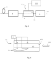
- Fig. 3 shows a manufacturing line for producing continuous rods or continuous rod components, preferably for aerosol-generating articles.
- hollow rods of cellulose acetate are manufactured that are cut into segments. These segments may be used in heat-not-burn aerosol-generating articles.
- the manufacturing line comprises a transport device 10 to transport continuous material, for example cellulose acetate tow material, along a transport or feeding direction 100.
- continuous material for example cellulose acetate tow material
- a preparation unit 7 is arranged.
- the tow material is fed to the preparation unit 7 by the transport device 3.
- the preparation unit 7 is adapted to form a continuous stream of tow material, moistened with a hardening fluid or plasticizer, such as for example triacetin.
- the plasticizer unit is part of the preparation unit 7.
- Plasticizer units are known in the art.
- the plasticizer unit may also be located upstream of the preparation unit 7. Downstream of the preparation unit 7, the manufacturing line includes a forming apparatus 4, arranged in series to the preparation unit 7.
- the forming apparatus 4 is adapted to receive the flow of tow material and to cause hardening of the material to transform the tow material into a continuous axially rigid rod.
- the manufacturing line further includes a wrapping unit 8, to wrap the rod in a wrapping paper.
- the manufacturing line may comprise a cutting unit 9, preferably a rotating cutting head of known type.
- the cutting unit 9 is arranged downstream of the forming apparatus 4 and wrapping unit 9 and adapted to cut the rod into rod segments. A desired length of the segments in which the rod is cut is for example obtained with the assistance of an appropriate measuring device (not shown).
- Suitable wrapping unit 8, transport device 10 and cutting unit 9 are known in the art and not further described.
- the manufacturing line includes a main control system 500 adapted to receive and send signals from and to the forming apparatus 4.
- the main control system 500 for example pressure regulators may be controlled or, if present, the heating or non-heating of a temperature control unit.
- the main control system 500 also controls further units of the manufacturing line, for example the preparation unit 7 and the transport device 10.
- the wrapping unit 8 and cutting unit 9 may be controlled by the main control system 500.
- the forming apparatus 4 is shown in an enlarged view in Fig. 4 .
- the forming apparatus 4 comprises a tubular element 41 adapted to receive the tow material saturated with hardening material.
- the transport direction of the transport device 10, as well as the feeding direction of the tow material into the tubular element 41 of the forming apparatus 4 is depicted with arrow 100.
- the tubular element 41 is adapted to shape the tow material to transform it into a generally cylindrical rod, for example into a full rod or into a hollow rod, and to advance the rod in the feed direction 100 to the further components of the manufacturing line.
- the tubular element 41 defines a hole 45 through which the tow material can pass.
- the hole 45 comprises an inner surface 451.
- the inner surface 451 compresses the tow material to form a substantially cylindrical rod-like shaped continuous tow of material.
- the tubular element 41 is a single continuous tubular element comprising two injection sites for the pressurized fluid to act on the continuous material.
- more than two, for example three to five nozzles 21 are present for injecting pressurized fluid at three to five injections sites arranged along the tubular element 41.
- the formed inner tube comprises a substantially circular cross section.
- the formed inner tube 44 creates a number of flutes along the periphery of the formed tow, for example for air to pass along the flutes.
- all tubular element segments 410 of the tubular element 41 comprise an inner tube 44.
- upstream arranged element segments 410 that are provided with overheated steam for heating the tow material are provided with an inner tube 44.
Landscapes
- Engineering & Computer Science (AREA)
- Mechanical Engineering (AREA)
- Chemical & Material Sciences (AREA)
- Composite Materials (AREA)
- Physics & Mathematics (AREA)
- Health & Medical Sciences (AREA)
- Oral & Maxillofacial Surgery (AREA)
- Thermal Sciences (AREA)
- Materials Engineering (AREA)
- Yarns And Mechanical Finishing Of Yarns Or Ropes (AREA)
- Manufacture Of Macromolecular Shaped Articles (AREA)
- Moulding By Coating Moulds (AREA)
- Processing And Handling Of Plastics And Other Materials For Molding In General (AREA)
- Treatment Of Fiber Materials (AREA)
- Spinning Methods And Devices For Manufacturing Artificial Fibers (AREA)
- Cigarettes, Filters, And Manufacturing Of Filters (AREA)
Claims (14)
- Appareil de formation comprenant :un trajet de transport comportant un trajet d'apport pour apporter en continu un matériau d'étoupe continu (1) le long d'une direction de transport (100) du trajet de transport ;un dispositif de formation (4) raccordé à une extrémité aval du trajet d'apport et adapté pour former le matériau d'étoupe continu en une tige tubulaire continue, le dispositif de formation comprenant :un élément tubulaire (41) adapté pour permettre au matériau d'étoupe continu de passer à travers l'élément tubulaire pour former la tige tubulaire continue ;un compresseur de fluide (2) adapté pour générer un fluide sous pression, le compresseur de fluide étant en raccordement fluidique avec l'élément tubulaire pour fournir un fluide sous pression au matériau d'étoupe continu afin de chauffer ou de refroidir le matériau d'étoupe continu ;dans lequel le dispositif de formation comprend en outre plusieurs conduits de fluide (20) pour fournir du fluide sous pression depuis le compresseur de fluide à plusieurs sites d'injection (210) agencés le long du trajet de transport, caractérisé en ce qu'au moins deux conduits de fluide des plusieurs conduits de fluide comprennent une unité de commande de pression (5) comportant un capteur de pression (51) et un influenceur de pression (52), et en ce que les unités de commande de pression sont agencées dans des sections d'extrémité des au moins deux conduits de fluide au niveau des sites d'injection.
- Appareil de formation selon la revendication 1, dans lequel les influenceurs de pression sont des régulateurs de pression (52) capables de diminuer ou d'augmenter une pression du fluide sous pression dans les au moins deux conduits de fluide.
- Appareil de formation selon l'une quelconque des revendications précédentes, dans lequel chaque conduit de fluide des plusieurs conduits de fluide comprend une unité de commande de pression (5).
- Appareil de formation selon l'une quelconque des revendications précédentes, dans lequel au moins certains des plusieurs sites d'injection sont agencés le long d'une longueur de l'élément tubulaire.
- Appareil de formation selon l'une quelconque des revendications précédentes, dans lequel une extrémité d'injection des au moins deux conduits de fluide comprend une buse (21).
- Appareil de formation selon l'une quelconque des revendications précédentes, dans lequel l'élément tubulaire comprend une pluralité de segments d'élément tubulaire (410), dans lequel chaque segment d'élément tubulaire comprend un site d'injection.
- Appareil de formation selon l'une quelconque des revendications précédentes, dans lequel le compresseur de fluide est un générateur de vapeur adapté pour générer de la vapeur surchauffée pour fournir de la vapeur surchauffée à un matériau d'étoupe continu dans l'élément tubulaire ou dans lequel le compresseur de fluide est un compresseur d'air adapté pour générer de l'air sous pression afin de fournir de l'air sous pression au matériau d'étoupe continu dans l'élément tubulaire.
- Appareil de formation selon l'une quelconque des revendications précédentes, dans lequel au moins l'un des conduits de fluide parmi les plusieurs conduits de fluide comprend une unité de commande de température (3) comprenant un capteur de température (31) et un influenceur de température (30).
- Ligne de fabrication pour la fabrication d'une tige tubulaire continue, la ligne de fabrication comprenant un appareil de formation selon l'une quelconque des revendications précédentes et comprenant un dispositif d'application de plastifiant (7) agencé en amont de l'appareil de formation pour appliquer le plastifiant sur le matériau d'étoupe continu.
- Procédé pour former une tige tubulaire continue à partir d'un matériau d'étoupe continu, le procédé comprenant :la fourniture d'un matériau d'étoupe continu ;la formation du matériau d'étoupe continu en une tige tubulaire continue dans un dispositif de formation ;le chauffage ou le refroidissement du matériau d'étoupe continu pendant le formation en fournissant du fluide sous pression, à partir d'un compresseur de fluide via un système de distribution de fluide, au matériau d'étoupe continu, mesurant ainsi la pression du fluide sous pression dans au moins deux conduits de fluide du système de distribution et fournissant ainsi au moins deux influenceurs de pression dans le système de distribution en aval du compresseur de fluide, les influenceurs de pression étant capables de changer une pression du fluide sous pression délivré depuis le compresseur de fluide vers le matériau d'étoupe continu, mesurant et adaptant ainsi la pression du fluide sous pression à proximité des sites d'injection du fluide sous pression.
- Procédé selon la revendication 10, dans lequel le changement d'une pression du fluide sous pression délivré depuis le compresseur de fluide vers matériau d'étoupe continu comprend l'augmentation ou la diminution de la pression par une action de propulsion du fluide sous pression.
- Procédé selon l'une quelconque des revendications 10 ou 11, comprenant la mesure de la température du fluide sous pression au niveau du site d'injection et la fourniture d'un influenceur de température (30) dans le système de distribution, l'influenceur de température étant capable de changer la température du fluide sous pression délivré au matériau d'étoupe continu.
- Procédé selon la revendication 12, dans lequel l'influenceur de température comprend un élément de chauffage et de refroidissement.
- Procédé selon l'une quelconque des revendications 10 à 13, dans lequel le matériau d'étoupe continu est de l'acétate de cellulose et la tige tubulaire continue est un tube d'acétate creux (HAT) continu.
Applications Claiming Priority (2)
| Application Number | Priority Date | Filing Date | Title |
|---|---|---|---|
| EP19165803 | 2019-03-28 | ||
| PCT/EP2020/058149 WO2020193545A1 (fr) | 2019-03-28 | 2020-03-24 | Appareil de formage et procédé de formage d'une tige tubulaire continue à partir d'un matériau d'étoupe continu |
Publications (3)
| Publication Number | Publication Date |
|---|---|
| EP3945874A1 EP3945874A1 (fr) | 2022-02-09 |
| EP3945874B1 true EP3945874B1 (fr) | 2024-11-20 |
| EP3945874C0 EP3945874C0 (fr) | 2024-11-20 |
Family
ID=66001002
Family Applications (1)
| Application Number | Title | Priority Date | Filing Date |
|---|---|---|---|
| EP20711980.1A Active EP3945874B1 (fr) | 2019-03-28 | 2020-03-24 | Appareil et procédé de formation d'une tige tubulaire continu à partir d'un matériau d'étoupe continu |
Country Status (10)
| Country | Link |
|---|---|
| US (1) | US11779047B2 (fr) |
| EP (1) | EP3945874B1 (fr) |
| JP (1) | JP7565940B2 (fr) |
| KR (1) | KR102879209B1 (fr) |
| CN (1) | CN113677223B (fr) |
| BR (1) | BR112021018948A2 (fr) |
| ES (1) | ES2998466T3 (fr) |
| HU (1) | HUE069634T2 (fr) |
| PL (1) | PL3945874T3 (fr) |
| WO (1) | WO2020193545A1 (fr) |
Family Cites Families (18)
| Publication number | Priority date | Publication date | Assignee | Title |
|---|---|---|---|---|
| US3313665A (en) * | 1963-06-04 | 1967-04-11 | American Filtrona Corp | Method for making fibrous bodies |
| US3560298A (en) | 1968-07-30 | 1971-02-02 | Reynolds Tobacco Co R | Paperless cigarette filter and apparatus for manufacture thereof |
| JPS5033104B2 (fr) * | 1971-12-27 | 1975-10-27 | ||
| WO1989000014A1 (fr) | 1987-07-02 | 1989-01-12 | Gbe International Plc | Appareil permettant de dilater et/ou de secher une matiere particulaire |
| WO2012132972A1 (fr) | 2011-03-31 | 2012-10-04 | 日本たばこ産業株式会社 | Dispositif de fabrication de filtre, procédé de fabrication de filtre qui utilise ce dernier et filtre creux |
| DE102013104057A1 (de) | 2013-04-22 | 2014-10-23 | Hauni Maschinenbau Ag | Anordnung und Verfahren zum Überführen stabförmiger Artikel der Tabak verarbeitenden Industrie von einer Sendereinheit an eine Empfängereinheit |
| CN203435668U (zh) | 2013-07-18 | 2014-02-19 | 成都蓉阳科技有限公司 | 一种分体式空气源余热回收烟草热泵烘干机组 |
| GB201420733D0 (en) | 2014-11-21 | 2015-01-07 | British American Tobacco Co | Apparatus and method for filter manufacture |
| ES2776431T3 (es) | 2014-12-16 | 2020-07-30 | Philip Morris Products Sa | Método y aparato para conformar material continuo sustancialmente plano |
| ITUB20151932A1 (it) * | 2015-07-06 | 2017-01-06 | Gd Spa | Metodo e macchina per la realizzazione di filtri |
| EP3340815B1 (fr) | 2015-08-24 | 2019-07-03 | Philip Morris Products S.a.s. | Appareil et procédé de séchage de tiges de filtre |
| RU2714790C2 (ru) * | 2015-11-27 | 2020-02-19 | Филип Моррис Продактс С.А. | Аппарат для изготовления фильтров |
| CN108471803B (zh) * | 2015-11-30 | 2021-02-09 | 菲利普莫里斯生产公司 | 过滤器制造设备 |
| ITUB20159703A1 (it) * | 2015-12-15 | 2017-06-15 | Top Glass Eu Sa | Apparecchiatura e procedimento per realizzare corpi allungati cavi in materiale composito |
| KR102296584B1 (ko) | 2015-12-23 | 2021-09-01 | 코오롱인더스트리 주식회사 | 담배필터용 라이오셀 소재 및 그 제조방법 |
| WO2017114871A1 (fr) * | 2015-12-30 | 2017-07-06 | Philip Morris Products S.A. | Appareil de fabrication de filtre |
| GB201608815D0 (en) | 2016-05-19 | 2016-07-06 | British American Tobacco Co | Filter rod and apparatus and method |
| CN113661066B (zh) | 2019-03-28 | 2024-09-17 | 菲利普莫里斯生产公司 | 形成连续管状杆的成形设备和方法 |
-
2020
- 2020-03-24 EP EP20711980.1A patent/EP3945874B1/fr active Active
- 2020-03-24 PL PL20711980.1T patent/PL3945874T3/pl unknown
- 2020-03-24 JP JP2021557170A patent/JP7565940B2/ja active Active
- 2020-03-24 HU HUE20711980A patent/HUE069634T2/hu unknown
- 2020-03-24 WO PCT/EP2020/058149 patent/WO2020193545A1/fr not_active Ceased
- 2020-03-24 US US17/442,727 patent/US11779047B2/en active Active
- 2020-03-24 BR BR112021018948A patent/BR112021018948A2/pt active Search and Examination
- 2020-03-24 ES ES20711980T patent/ES2998466T3/es active Active
- 2020-03-24 KR KR1020217033694A patent/KR102879209B1/ko active Active
- 2020-03-24 CN CN202080024793.4A patent/CN113677223B/zh active Active
Also Published As
| Publication number | Publication date |
|---|---|
| WO2020193545A1 (fr) | 2020-10-01 |
| CN113677223B (zh) | 2024-04-02 |
| ES2998466T3 (en) | 2025-02-20 |
| EP3945874C0 (fr) | 2024-11-20 |
| PL3945874T3 (pl) | 2025-03-24 |
| HUE069634T2 (hu) | 2025-04-28 |
| BR112021018948A2 (pt) | 2022-02-01 |
| EP3945874A1 (fr) | 2022-02-09 |
| JP7565940B2 (ja) | 2024-10-11 |
| KR102879209B1 (ko) | 2025-11-03 |
| JP2022528352A (ja) | 2022-06-10 |
| US11779047B2 (en) | 2023-10-10 |
| KR20210143818A (ko) | 2021-11-29 |
| CN113677223A (zh) | 2021-11-19 |
| US20220184899A1 (en) | 2022-06-16 |
Similar Documents
| Publication | Publication Date | Title |
|---|---|---|
| US20250339997A1 (en) | Forming apparatus and method for forming a continuous tubular rod | |
| US4549875A (en) | Manufacture of tobacco smoke filters | |
| JP5388249B2 (ja) | フィルタ製造機 | |
| JP5522765B2 (ja) | フィルタ製造機及びこれを用いたフィルタ製造方法並びに中空フィルタ | |
| CN108348000A (zh) | 过滤器制造设备 | |
| WO2016079468A1 (fr) | Filtre, et appareil et procédé pour la fabrication de filtres | |
| US4770193A (en) | Manufacture of tobacco smoke filters | |
| US11779047B2 (en) | Forming apparatus and method for forming a continuous tubular rod from a continuous tow material | |
| CN105452494A (zh) | 用于经过热处理的金属产品的喷淋淬火系统 | |
| CN101421197A (zh) | 复合丝的制造方法和装置 | |
| WO2012131986A1 (fr) | Dispositif de fabrication de filtre et procédé de fabrication de filtre l'utilisant | |
| RU2810767C2 (ru) | Формовочная установка для формования непрерывного трубчатого стержня, производственная линия для изготовления непрерывного трубчатого стержня и способ формования непрерывного трубчатого стержня из непрерывного материала штранга | |
| RU2809649C2 (ru) | Формовочная установка и способ формования непрерывного трубчатого стержня | |
| BR112021018978B1 (pt) | Aparelho formador e método para formação de uma coluna tubular contínua | |
| EP3007570B1 (fr) | Procédé et patin pour presser des segments de filtre à segments multiples | |
| CN113453868A (zh) | 用于使用热塑性材料生产双轴定向管的方法和装置 | |
| JP2022528351A5 (fr) | ||
| JP2022528352A5 (fr) | ||
| RU2021131422A (ru) | Формовочная установка и способ формования непрерывного трубчатого стержня из непрерывного материала штранга | |
| KR20100136768A (ko) | 파이프 내부 냉각장치 | |
| RU2021130636A (ru) | Формовочная установка и способ формования непрерывного трубчатого стержня | |
| US3455765A (en) | Apparatus for producing fiber-reinforced plastics sections,particularly longitudinally tapering sections,with the aid of a mandrel | |
| US6123536A (en) | Plant for the production of plastic tubular films with a biaxial orientation and an in-line stabilization phase | |
| JPH06504099A (ja) | 加熱されてペーストを形成する物質からヤーンを生成するための押出ヘッド |
Legal Events
| Date | Code | Title | Description |
|---|---|---|---|
| STAA | Information on the status of an ep patent application or granted ep patent |
Free format text: STATUS: UNKNOWN |
|
| STAA | Information on the status of an ep patent application or granted ep patent |
Free format text: STATUS: THE INTERNATIONAL PUBLICATION HAS BEEN MADE |
|
| PUAI | Public reference made under article 153(3) epc to a published international application that has entered the european phase |
Free format text: ORIGINAL CODE: 0009012 |
|
| STAA | Information on the status of an ep patent application or granted ep patent |
Free format text: STATUS: REQUEST FOR EXAMINATION WAS MADE |
|
| 17P | Request for examination filed |
Effective date: 20211018 |
|
| AK | Designated contracting states |
Kind code of ref document: A1 Designated state(s): AL AT BE BG CH CY CZ DE DK EE ES FI FR GB GR HR HU IE IS IT LI LT LU LV MC MK MT NL NO PL PT RO RS SE SI SK SM TR |
|
| DAV | Request for validation of the european patent (deleted) | ||
| DAX | Request for extension of the european patent (deleted) | ||
| STAA | Information on the status of an ep patent application or granted ep patent |
Free format text: STATUS: EXAMINATION IS IN PROGRESS |
|
| 17Q | First examination report despatched |
Effective date: 20221031 |
|
| GRAP | Despatch of communication of intention to grant a patent |
Free format text: ORIGINAL CODE: EPIDOSNIGR1 |
|
| STAA | Information on the status of an ep patent application or granted ep patent |
Free format text: STATUS: GRANT OF PATENT IS INTENDED |
|
| GRAS | Grant fee paid |
Free format text: ORIGINAL CODE: EPIDOSNIGR3 |
|
| GRAA | (expected) grant |
Free format text: ORIGINAL CODE: 0009210 |
|
| STAA | Information on the status of an ep patent application or granted ep patent |
Free format text: STATUS: THE PATENT HAS BEEN GRANTED |
|
| INTG | Intention to grant announced |
Effective date: 20240918 |
|
| AK | Designated contracting states |
Kind code of ref document: B1 Designated state(s): AL AT BE BG CH CY CZ DE DK EE ES FI FR GB GR HR HU IE IS IT LI LT LU LV MC MK MT NL NO PL PT RO RS SE SI SK SM TR |
|
| REG | Reference to a national code |
Ref country code: GB Ref legal event code: FG4D |
|
| REG | Reference to a national code |
Ref country code: CH Ref legal event code: EP |
|
| REG | Reference to a national code |
Ref country code: DE Ref legal event code: R096 Ref document number: 602020041613 Country of ref document: DE |
|
| REG | Reference to a national code |
Ref country code: IE Ref legal event code: FG4D |
|
| U01 | Request for unitary effect filed |
Effective date: 20241120 |
|
| U07 | Unitary effect registered |
Designated state(s): AT BE BG DE DK EE FI FR IT LT LU LV MT NL PT RO SE SI Effective date: 20241127 |
|
| REG | Reference to a national code |
Ref country code: ES Ref legal event code: FG2A Ref document number: 2998466 Country of ref document: ES Kind code of ref document: T3 Effective date: 20250220 |
|
| PG25 | Lapsed in a contracting state [announced via postgrant information from national office to epo] |
Ref country code: HR Free format text: LAPSE BECAUSE OF FAILURE TO SUBMIT A TRANSLATION OF THE DESCRIPTION OR TO PAY THE FEE WITHIN THE PRESCRIBED TIME-LIMIT Effective date: 20241120 Ref country code: IS Free format text: LAPSE BECAUSE OF FAILURE TO SUBMIT A TRANSLATION OF THE DESCRIPTION OR TO PAY THE FEE WITHIN THE PRESCRIBED TIME-LIMIT Effective date: 20250320 |
|
| PG25 | Lapsed in a contracting state [announced via postgrant information from national office to epo] |
Ref country code: NO Free format text: LAPSE BECAUSE OF FAILURE TO SUBMIT A TRANSLATION OF THE DESCRIPTION OR TO PAY THE FEE WITHIN THE PRESCRIBED TIME-LIMIT Effective date: 20250220 |
|
| PG25 | Lapsed in a contracting state [announced via postgrant information from national office to epo] |
Ref country code: GR Free format text: LAPSE BECAUSE OF FAILURE TO SUBMIT A TRANSLATION OF THE DESCRIPTION OR TO PAY THE FEE WITHIN THE PRESCRIBED TIME-LIMIT Effective date: 20250221 |
|
| REG | Reference to a national code |
Ref country code: HU Ref legal event code: AG4A Ref document number: E069634 Country of ref document: HU |
|
| PG25 | Lapsed in a contracting state [announced via postgrant information from national office to epo] |
Ref country code: RS Free format text: LAPSE BECAUSE OF FAILURE TO SUBMIT A TRANSLATION OF THE DESCRIPTION OR TO PAY THE FEE WITHIN THE PRESCRIBED TIME-LIMIT Effective date: 20250220 |
|
| U20 | Renewal fee for the european patent with unitary effect paid |
Year of fee payment: 6 Effective date: 20250325 |
|
| PG25 | Lapsed in a contracting state [announced via postgrant information from national office to epo] |
Ref country code: SM Free format text: LAPSE BECAUSE OF FAILURE TO SUBMIT A TRANSLATION OF THE DESCRIPTION OR TO PAY THE FEE WITHIN THE PRESCRIBED TIME-LIMIT Effective date: 20241120 |
|
| PGFP | Annual fee paid to national office [announced via postgrant information from national office to epo] |
Ref country code: ES Payment date: 20250429 Year of fee payment: 6 |
|
| PGFP | Annual fee paid to national office [announced via postgrant information from national office to epo] |
Ref country code: CH Payment date: 20250401 Year of fee payment: 6 |
|
| PG25 | Lapsed in a contracting state [announced via postgrant information from national office to epo] |
Ref country code: SK Free format text: LAPSE BECAUSE OF FAILURE TO SUBMIT A TRANSLATION OF THE DESCRIPTION OR TO PAY THE FEE WITHIN THE PRESCRIBED TIME-LIMIT Effective date: 20241120 |
|
| PG25 | Lapsed in a contracting state [announced via postgrant information from national office to epo] |
Ref country code: CZ Free format text: LAPSE BECAUSE OF FAILURE TO SUBMIT A TRANSLATION OF THE DESCRIPTION OR TO PAY THE FEE WITHIN THE PRESCRIBED TIME-LIMIT Effective date: 20241120 |
|
| PLBE | No opposition filed within time limit |
Free format text: ORIGINAL CODE: 0009261 |
|
| STAA | Information on the status of an ep patent application or granted ep patent |
Free format text: STATUS: NO OPPOSITION FILED WITHIN TIME LIMIT |
|
| PG25 | Lapsed in a contracting state [announced via postgrant information from national office to epo] |
Ref country code: MC Free format text: LAPSE BECAUSE OF FAILURE TO SUBMIT A TRANSLATION OF THE DESCRIPTION OR TO PAY THE FEE WITHIN THE PRESCRIBED TIME-LIMIT Effective date: 20241120 |
|
| 26N | No opposition filed |
Effective date: 20250821 |
|
| PG25 | Lapsed in a contracting state [announced via postgrant information from national office to epo] |
Ref country code: IE Free format text: LAPSE BECAUSE OF NON-PAYMENT OF DUE FEES Effective date: 20250324 |
|
| REG | Reference to a national code |
Ref country code: CH Ref legal event code: U11 Free format text: ST27 STATUS EVENT CODE: U-0-0-U10-U11 (AS PROVIDED BY THE NATIONAL OFFICE) Effective date: 20260401 |
|
| PGFP | Annual fee paid to national office [announced via postgrant information from national office to epo] |
Ref country code: GB Payment date: 20260324 Year of fee payment: 7 |
|
| PGFP | Annual fee paid to national office [announced via postgrant information from national office to epo] |
Ref country code: HU Payment date: 20260323 Year of fee payment: 7 |
|
| PGFP | Annual fee paid to national office [announced via postgrant information from national office to epo] |
Ref country code: TR Payment date: 20260323 Year of fee payment: 7 |
|
| PGFP | Annual fee paid to national office [announced via postgrant information from national office to epo] |
Ref country code: PL Payment date: 20260324 Year of fee payment: 7 |
|
| U20 | Renewal fee for the european patent with unitary effect paid |
Year of fee payment: 7 Effective date: 20260326 |