EP3946063B1 - Procédé d'utilisation de mesures temporelles de rayonnement localisé pour estimer l'amplitude, l'emplacement et le volume de matériau radioactif dans le corps - Google Patents
Procédé d'utilisation de mesures temporelles de rayonnement localisé pour estimer l'amplitude, l'emplacement et le volume de matériau radioactif dans le corps Download PDFInfo
- Publication number
- EP3946063B1 EP3946063B1 EP20784501.7A EP20784501A EP3946063B1 EP 3946063 B1 EP3946063 B1 EP 3946063B1 EP 20784501 A EP20784501 A EP 20784501A EP 3946063 B1 EP3946063 B1 EP 3946063B1
- Authority
- EP
- European Patent Office
- Prior art keywords
- sensor
- location
- signal data
- radioactive
- volume
- Prior art date
- Legal status (The legal status is an assumption and is not a legal conclusion. Google has not performed a legal analysis and makes no representation as to the accuracy of the status listed.)
- Active
Links
Images








Classifications
-
- A—HUMAN NECESSITIES
- A61—MEDICAL OR VETERINARY SCIENCE; HYGIENE
- A61B—DIAGNOSIS; SURGERY; IDENTIFICATION
- A61B6/00—Apparatus or devices for radiation diagnosis; Apparatus or devices for radiation diagnosis combined with radiation therapy equipment
- A61B6/40—Arrangements for generating radiation specially adapted for radiation diagnosis
- A61B6/4057—Arrangements for generating radiation specially adapted for radiation diagnosis by using radiation sources located in the interior of the body
-
- A—HUMAN NECESSITIES
- A61—MEDICAL OR VETERINARY SCIENCE; HYGIENE
- A61B—DIAGNOSIS; SURGERY; IDENTIFICATION
- A61B6/00—Apparatus or devices for radiation diagnosis; Apparatus or devices for radiation diagnosis combined with radiation therapy equipment
- A61B6/42—Arrangements for detecting radiation specially adapted for radiation diagnosis
- A61B6/4208—Arrangements for detecting radiation specially adapted for radiation diagnosis characterised by using a particular type of detector
- A61B6/4258—Arrangements for detecting radiation specially adapted for radiation diagnosis characterised by using a particular type of detector for detecting non x-ray radiation, e.g. gamma radiation
-
- A—HUMAN NECESSITIES
- A61—MEDICAL OR VETERINARY SCIENCE; HYGIENE
- A61B—DIAGNOSIS; SURGERY; IDENTIFICATION
- A61B6/00—Apparatus or devices for radiation diagnosis; Apparatus or devices for radiation diagnosis combined with radiation therapy equipment
- A61B6/42—Arrangements for detecting radiation specially adapted for radiation diagnosis
- A61B6/4266—Arrangements for detecting radiation specially adapted for radiation diagnosis characterised by using a plurality of detector units
-
- A—HUMAN NECESSITIES
- A61—MEDICAL OR VETERINARY SCIENCE; HYGIENE
- A61B—DIAGNOSIS; SURGERY; IDENTIFICATION
- A61B6/00—Apparatus or devices for radiation diagnosis; Apparatus or devices for radiation diagnosis combined with radiation therapy equipment
- A61B6/48—Diagnostic techniques
- A61B6/486—Diagnostic techniques involving generating temporal series of image data
-
- A—HUMAN NECESSITIES
- A61—MEDICAL OR VETERINARY SCIENCE; HYGIENE
- A61B—DIAGNOSIS; SURGERY; IDENTIFICATION
- A61B6/00—Apparatus or devices for radiation diagnosis; Apparatus or devices for radiation diagnosis combined with radiation therapy equipment
- A61B6/50—Apparatus or devices for radiation diagnosis; Apparatus or devices for radiation diagnosis combined with radiation therapy equipment specially adapted for specific body parts; specially adapted for specific clinical applications
- A61B6/504—Apparatus or devices for radiation diagnosis; Apparatus or devices for radiation diagnosis combined with radiation therapy equipment specially adapted for specific body parts; specially adapted for specific clinical applications for diagnosis of blood vessels, e.g. by angiography
-
- G—PHYSICS
- G01—MEASURING; TESTING
- G01T—MEASUREMENT OF NUCLEAR OR X-RADIATION
- G01T1/00—Measuring X-radiation, gamma radiation, corpuscular radiation, or cosmic radiation
- G01T1/16—Measuring radiation intensity
- G01T1/161—Applications in the field of nuclear medicine, e.g. in vivo counting
- G01T1/164—Scintigraphy
- G01T1/1641—Static instruments for imaging the distribution of radioactivity in one or two dimensions using one or several scintillating elements; Radio-isotope cameras
-
- G—PHYSICS
- G01—MEASURING; TESTING
- G01T—MEASUREMENT OF NUCLEAR OR X-RADIATION
- G01T7/00—Details of radiation-measuring instruments
- G01T7/005—Details of radiation-measuring instruments calibration techniques
-
- A—HUMAN NECESSITIES
- A61—MEDICAL OR VETERINARY SCIENCE; HYGIENE
- A61B—DIAGNOSIS; SURGERY; IDENTIFICATION
- A61B6/00—Apparatus or devices for radiation diagnosis; Apparatus or devices for radiation diagnosis combined with radiation therapy equipment
- A61B6/02—Arrangements for diagnosis sequentially in different planes; Stereoscopic radiation diagnosis
- A61B6/03—Computed tomography [CT]
- A61B6/037—Emission tomography
Definitions
- the present invention relates to systems, devices, and methods of measuring and quantifying the magnitude, location, and/or volume of radioactive material in the body. More particularly, the present disclosure teaches novel systems, devices and methods of determining and/or quantifying the amount of radioactive material in an area of interest in the body, whether the radioactive material be introduced via an infiltrated injection, uptake in a tumor, uptake in an organ, or any other introduction of radioactive material to all or part of the body, or radioactive material anywhere generally.
- Radiopharmaceuticals or radiotracers may be interested in knowing if a prescribed cancer therapy is having an intended effect, in order to improve outcomes, minimize side effects, and avoid unnecessary expenses.
- Cytotoxic treatments for example, kill tumor cells.
- Cytostatic treatments for example, inhibit cell growth leaving tumors the same size, but preventing the spread of the disease.
- immunotherapy treatments use the body's immune system to attack the cancer and initially result in an inflammatory response in the tumor area before there is evidence that the body is effectively attacking the tumor.
- Imaging tools provide more precise measurements for tumors both close to the surface and in deep tissue, but again primarily measure size, not the ideal indicator.
- Molecular imaging single-photon emission computerized tomography (SPECT) or PET/CT scan, for example) may capture the gamma particle emissions from injected radio-labeled tracers captured by live cancer cells and is routinely used for pre-therapy staging of cancer.
- Visually identifying metastatic disease is the primary means of staging cancer; however, semi-quantitative measurements, for example the Standardized Uptake Value (SUV), may also be used to stage cancer and other conditions.
- semi-quantitative measurements may be used to help determine whether lung nodules are malignant, or brain function is deteriorating.
- SUV Standardized Uptake Value
- semi-quantitative measurements may include a ratio of the amount of radio-labeled tracer in an area of interest (e.g., a tumor) compared to the level in a reference area, for example the rest of the body.
- an area of interest e.g., a tumor
- a reference area for example the rest of the body.
- SPECT imaging using I-Ioflupane is another sensitive imaging technique.
- SPECT imaging may be used to detect or classify certain diseases, including diseases of the brain such as Parkinsonian Syndromes.
- diseases of the brain such as Parkinsonian Syndromes.
- it may be desirable to distinguish certain neurodegenerative Parkinsonian Syndromes from other non-degenerative Parkinsonian Syndromes and other tremor disorders.
- SPECT images may be used to make such distinctions.
- scans may be characterized by intense and symmetric DAT binding in the caudate nucleus and putamen on both hemispheres of the brain, as opposed to asymmetric measurements that may indicate degenerative conditions.
- asymmetric measurements that may indicate degenerative conditions. See, e.g ., R. Prashanth, S. Dutta Roy, P. Mandal, and S. Ghosh, "High Accuracy Classification of Parkinson's Disease through Shape Analysis and Surface Fitting in 123I-Ioflupane SPECT Imaging," IEEE-JBHI Journal (2016 ).
- Quantifying these measurements in one or more locations, or otherwise enabling a comparison between regions of the body or organ may provide helpful diagnostic or other information (e.g., estimations of the Striatal Binding Ratio (SBR)). It may be possible, for example, to use such information to diagnose degenerative brain conditions using such techniques (and/or eliminate such diagnoses).
- SBR Striatal Binding Ratio
- US2018172844A1 discloses the use of fitting to reference data sets to establish if signal data represents a proper or improper administration of radio analyte.
- Certain aspects of the systems and methods disclosed in the references identified above relate to, among other things, the detection and quantification of infiltrations during injections of radio-labeled radiotracers (i.e., non-bolus injections).
- radiopharmaceuticals are typically injected intravenously.
- the injection should be administered as a bolus that results in complete and prompt systemic distribution of the radiopharmaceutical.
- An extravasation, or infiltration occurs when an injected substance leaks into surrounding tissue instead of remaining within the vasculature as intended. Extravasations can be caused by improper placement of the intravenous access (IV), erosion or degradation of the vessel wall, or failure of vessel integrity.
- Extravasations reduce the net available activity for uptake and alter the uptake kinetics for subsequent imaging. Extravasations may also undesirably expose tissue surrounding the extravasation to unacceptable doses of radiation.
- a portion of the radio-tracer may go directly to the bloodstream while a portion remains embedded in tissue around the injection site.
- the radio-tracer embedded in the tissue may still ultimately reach the bloodstream, albeit at a time later than the initial injection, thereby affecting certain assumptions in dosage and delivery made by the clinicians.
- non-bolus injections may alter the metrics measured by, for example, a PET scan dynamically over a period of time (e.g., kinetic analysis, Patlak, etc.), and because the dynamic variation depends on the nature of the infiltration itself (i.e., varies from infiltration to infiltration), a system and method for measuring the delivery of radio-tracer from an infiltrated injection to the bloodstream as a function of time may provide critical information to clinicians.
- a system and method for measuring the delivery of radio-tracer from an infiltrated injection to the bloodstream as a function of time may provide critical information to clinicians.
- the systems and methods provided herein may be utilized to ultimately provide a correction factor that may be applied to a measured SUV, among other things.
- radiopharmaceutical extravasations can result in high activity remaining near the injection site that exposes the tissue to significant dose.
- Existing dosimetry techniques may not be suitable for extravasations because they do not accurately account for changes in extravasated activity or volume over time.
- scintillation detectors that record time-activity curves (TACs) of the activity near the injection site may be a practical way to gather this information. For example, the rate of biological clearance of the extravasate may be determined with TAC data.
- initial extravasation activity may be estimated by extrapolating back to the time of injection.
- One aspect of the methods and systems described is to have an understanding of the magnitude/amplitude, location, and/or volume of, for example, an infiltrated portion of a radio-tracer injection as a function of time.
- such information may be determined by using, for example, nuclear medicine imaging techniques (e.g., PET scan).
- nuclear medicine imaging techniques e.g., PET scan
- the radioactive source of interest may be outside the imaging device's field of view, or may not be able to be determined until after the radioactive source has dissipated or moved, etc. It may also be advantageous to determine this information without relying on an expensive nuclear imaging system (e.g., PET scan, etc.).
- such systems, devices and methods may be used to quantify and otherwise understand the uptake of radioactive material in a tumor over time, precise organ dosimetry of radiopharmaceuticals, uptake of radiopharmaceuticals in other areas of interest in the body (e.g., brain (basil ganglia), other organs, other tissues, etc.), and other circumstances.
- a nuclear medicine imaging device e.g., SPECT or PET scanner
- one or more sensors may be used to measure, for example, radiation activity over a period of time.
- sensors such as those taught in U.S. Patent No. 9,002,438 and U.S. 9,939,533 may be used, though other sensors for measuring radiation activity may also be utilized.
- information obtained by those sensor(s) may then be used to measure, determine or estimate the amplitude of a radioactive source in the body over a period of time of interest, in addition to the location and/or volume of a radioactive source. Such information may also be used to estimate a dose of radiation to surrounding tissue. Such information can also be used to quantify uptake or delivery of radiopharmaceuticals in a tumor or organ, quantify change in uptake or delivery over time (either over the course of a single treatment or by comparison of multiple sessions over hours, days, weeks, months or years), and/or quantify such uptake or delivery in two or more parts of the body to determine useful comparison measurements (e.g., comparisons between hemispheres of the brain, etc.).
- a method for the ex vivo real-time detection over a period of time of radiation emitted by a subject from the administration of a radioactive analyte that decays in vivo may include applying one or more ex vivo radiation measurement sensors proximate to a point of administration on the subject of the radioactive analyte, and detecting radiation over a desired period of time and producing signal data associated with the desired period of time.
- the measurement sensor may have at least one sensor output for such signal data, and outputting the signal data.
- the signal data may be processed using a computer processor in operative communication with a non-transient memory and the measurement sensor output, and more particularly, may receive the signal data associated with the desired period of time, use a measured value of radioactive material proximate the point of administration at a time t to estimate a function of radioactive material proximate the point of administration from a time of administration to the time t based on the signal data associated with the desired period of time, and determine, based on the estimated function of radioactive material proximate the point of administration, an amount of radioactive material disposed in body tissue proximate the point of injection from the time of administration to the time t.
- the method may include the step of amplifying the signal data using a signal amplifier in operable communication with the radiation sensor.
- the measured value of radioactive material proximate the point of administration at time t may be measured using an array of two or more ex vivo radiation measurement sensors.
- the array may have a known geometry and relative distances between the sensors may be known. It may then be possible, according to some embodiments, to determine a distance from the array (and/or each sensor of the array) to a radiometric center of the radioactive material to estimate a location in the body of the radiometric center of the radioactive material over a period of time.
- the array may be used to determine a volume associated with the radioactive material over a period of time.
- a system for the ex vivo real-time detection over a period of time of radiation emitted by a subject from the administration of a radioactive analyte that decays in vivo may include at least one ex vivo radiation measurement sensor to detect radiation over a desired period of time and to produce signal data associated with the desired period of time, and the ex vivo measurement sensor may be adapted to sense radiation proximate a point of administration on the subject of the radioactive analyte.
- the system may also include a signal amplifier that may be in operable communication with the gamma radiation sensor. The signal amplifier may be adapted to amplify the signal data, and the measurement sensor may have at least one sensor output for such amplified signal data.
- the system may also include at least one computer processor and a non-transient memory, where the computer processor may be in operable communication with the non-transient memory and the measurement sensor output port.
- the non-transient memory may include computer program code executable by the at least one computer processor, and the computer program code may be configured for performing the steps of receiving the amplified signal data with the desired period of time, accessing a measured amount of radioactive material proximate the point of administration at a time t, and using the amplified signal data, estimating a function of radioactive material proximate the point of injection as a function of time from a time of injection to time t.
- the system may also, in some embodiments, include a step of convolving the estimated function with a known impulse response from a typical bolus injection.
- the system may also calculate a correction factor to be applied to one or more measurements made using a nuclear imaging device.
- the system may measure a value of radioactive material proximate the point of administration at time t by using an array of two or more ex vivo radiation measurement sensors.
- the array may have a known geometry and have known relative distances between the sensors such that a distance from the array to a radiometric center of the radioactive material being measured may be determined.
- the system may also determine a volume of the radioactive material being measured.
- a method for the ex vivo real-time determination over a period of time of one or more of the magnitude, location, and volume of radioactive material in the body by measuring radiation that decays in vivo emitted by a subject may include the steps of applying one or more ex vivo radiation measurement sensors to or proximate an area of interest on a patient, and detecting radiation over a desired period of time and producing signal data associated with the desired period of time.
- the method may also include amplifying the signal data using, for example, a signal amplifier that may be in operable communication with the radiation sensor.
- the measurement sensor may include at least one sensor output for such amplified signal data, and may also output the amplified signal data.
- the amplified signal data may be processed using, for example, a computer processor in operative communication with a non-transient memory and the measurement sensor output, and the processor may perform the steps of receiving the amplified signal data associated with the desired period of time, and comparing the amplified signal data to a set of expected signal data for radioactive sources of various magnitudes, locations, and volumes.
- the method may also include determining one or more of a magnitude, location, and volume of the radioactive source in the body over the desired period of time by, in some embodiments, fitting the amplified signal data to the most likely set of expected signal data.
- the method used to fit the most likely magnitude, location, and volume of the radioactive source in the body may be the Maximum Likelihood Expectation Maximization method.
- the method may include the step of determining a dose of radioactivity to an area of tissue proximate the location of the radioactive source.
- the method may also include the step of using the determined one or more magnitude, location, and volume of radioactive source in the body to make one or more of a clinical decision or diagnosis.
- the method may include use of an array that may include two or more of the ex vivo radiation measurement sensors, and may also have the sensors disposed in a substantially symmetric geometry about the radioactive source in the body.
- the sensors may also be disposed proximate one or more desired measurement locations, and in some embodiments, each desired measurement location may include at least a first sensor disposed relatively closer to the radioactive source than a second sensor.
- the method may be used to determine one or more of a magnitude, location, or volume for two or more radiation sources in the body.
- the method may also include the step of comparing the one or more determined magnitude, location, or volume of the two or more radioactive sources, and making a clinical decision or diagnosis based on the comparison.
- the method may also make a clinical decision or diagnosis based on one or more prior determinations or comparisons of the subject patient, and/or using a comparison to a table or other source that includes data from a population of other patients.
- the present disclosure teaches, among other things, systems and methods for using measurements of localized radiation to estimate the magnitude, location, and/or volume of radioactive source materials in the body.
- measurements may be repeated at various points in time to determine temporal changes in magnitude, location, and/or volume of radioactive materials in the body.
- information may be used to correct for non-bolus injections of radiopharmaceuticals.
- systems and methods may allow physicians to better measure, for example, cancer treatment effectiveness.
- the systems, devices and methods may be used to validate organ dosimetry, or measure uptake of radiopharmaceuticals in tumors, organs or other areas of interest directly.
- the SUV of a tumor-for example, the ratio of the amount of radio-labeled tracer in an area of interest compared to the level in the rest of the body- may be calculated using, among other things, molecular imaging data.
- SUV may be approximated as the integral of concentration of radiotracer in the bloodstream, multiplied by a constant K, plus a variability of distribution volume factor (V d ).
- C T (t) represents the concentration of radiotracer in the tumor
- C B (t) represents the concentration of radiotracer in the blood
- K is a constant
- V d is a dimensionless volume of distribution equivalent to a volume of blood that contains the same activity as 1 mL of tissue.
- C T t K ⁇ 0 T C B t dt + V d
- the arterial input function or "AIF" may be referred to as the impulse response for a typical bolus injection, and such impulse responses have been well-studied and measured.
- the concentration of radiotracer in the blood cannot be assumed to be a typical bolus injection of known dosage, but instead varies over time as an infiltrated portion of a dose that relatively slowly finds its way to the bloodstream, the measured concentration of radiotracer in the tumor becomes a function of both the radiotracer in the bloodstream from the initial (partial) bolus injection, and the later added radiotracer from the infiltration portion. Further, because the magnitude (i.e. the activity) of the infiltration depends on the nature of the infiltration itself ( i.e.
- the effective dose into the bloodstream from the bolus portion may be reduced by an unknown amount.
- the SUV of an area of interest e.g., a tumor
- SUV i is the SUV in the case of an infiltrated injection
- the kinetics of radiotracer uptake can be considered a time-invariant linear system.
- a bolus injection could be the impulse and the normal AIF curve (i.e. concentration of radiotracer in the blood as a function of time) could then be the impulse response.
- the AIF for a typical bolus injection has been well-studied and measured, such that results and applicable measurements are readily available in the literature.
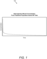
- Fig. 1 an exemplary AIF curve 100 for an ideal injection is presented, showing concentration of radiopharmaceutical in the blood on the y-axis vs. time on the x-axis.
- the AIF may be modeled as a convolution of the normal impulse response with the altered input signal that may comprise a decreased initial impulse (the bolus) followed by prolonged decaying exponential reabsorption.
- the reduced bolus portion may represent the amount of radiotracer that enters circulation immediately.
- the extended infusion portion may result from sequestered or infiltrated radiotracer being reabsorbed into circulation through, for example, the venous or lymphatic systems.
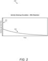
- Fig. 2 an exemplary graphical representation of a non-typical injection 200 (e.g., one having an infiltration) is presented, where the activity measured per unit time (y-axis) is expressed as a function of time (x-axis). As illustrated, there is an initial "spike" 201 corresponding to the bolus portion, followed by a gradual decaying exponential reabsorption portion 202.
- the injection is not a bolus, and thus the input to the linear system is not an impulse.
- the true input to the linear system from an extravasated or infiltrated injection is known or can be determined, it may be possible to then calculate how the altered injection shape may impact the scan metrics such as, for example, SUV (e.g. from a PET scan).
- SUV e.g. from a PET scan
- That convolution of functions can yield a function for concentration of radiotracer in the blood as a function of time (i.e. the Arterial Input Function or AIF) for any case of infiltration or extravasation.
- AIF Arterial Input Function
- FIG. 3 an exemplary graphical representation of an ideal bolus injection AIF (dotted line) alongside an AIF for an extravasation resulting in a 50% SUV (i.e. Area under the curve or AUC) reduction is presented.
- a user may need to know the amplitude (i.e. the activity) of the infiltration as well as the rate of reabsorption of the infiltrate (so as to produce the function of radiotracer entering circulation over time).
- localized radiation detectors such as those disclosed U.S. Patent Nos. 9,939,533 and 9,002,438 may be used to measure activity at the injection site as a function of time (i.e. time-activity curve or TAC).
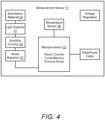
- a measurement sensor 11 may include, for example, a scintillation material 20; a light detector 21; and a sensor processor 22 with associated non-transient sensor memory 30, logic or sensor software 26, and other circuitry supporting these components in operable communication, optionally with a printed circuit board 23P ( FIG. 6 ).
- Such sensors may also include amplifier circuitry 33 and/or a temperature sensor 36.
- Measurement sensor 11 may utilize a scintillation material 20 to receive gamma radiation from positron emission decay and convert the radiation into photons, such as pulses of light, which may then be detected by the light detector 21.
- the sensor processor 22 may enable measurement and collection of the photons, such as the number of light pulses detected over a given amount of time.
- noise rejection 37 may be included that may provide a filter for filtering amplified signal data based on the height or amplitude of such pulses.
- noise rejection 37 may include a voltage comparator or an analog to digital converter with computer program code to compare the digital output to a reference level.
- Possible scintillation materials 20 include, but are not limited to: Bismuth Germanate (BOO); Gadolinium Oxyorthosilicate (GSO); Cerium-doped Lutetium Oxyorthosilicate (LSO); Cerium-doped Lutetium Yttrium Orthosilicate (LYSO); Thallium-doped Sodium Iodide (NaI(T1)); Plastic Scintillator (Polyvinyltoluene); or Cadmium Zinc Telluride (CZT).
- BOO Bismuth Germanate
- GSO Gadolinium Oxyorthosilicate
- LSO Cerium-doped Lutetium Oxyorthosilicate
- LYSO Cerium-doped Lutetium Yttrium Orthosilicate
- Thallium-doped Sodium Iodide NaI(T1)
- Plastic Scintillator Polyvinyltoluene
- Cadmium Zinc Telluride C
- scintillation materials 20 that do not require the use of a light detector 21 may be used.
- multiple scintillation materials 20, each with their own detection circuitry, may be included to enable a two or three dimensional array of measurements.
- the sensor(s) are capable of detecting alpha particles, beta particles, x-rays, gamma rays, and/or other particles/energy indicative of radioactive material.
- radiation sensors capable of detecting alpha particles, beta particles, x-rays, gamma rays or any other kind of radioactive decay particle/energy may be utilized depending on the desired application.
- Measurement of beta particles may be advantageous when assessing delivery of a radio-therapeutic to an area of the body as such drugs sometimes release beta particles. It may similarly be advantageous to ensure that certain beta particle (or other particle) emitting drugs or other substances not reach a certain part of the body. Thus, sensors could be used to confirm the absence of such substances.
- the senor be capable of detecting emissions from radioactive material, and further capable of transmitting or otherwise sharing information about those emissions to the system for processing. It may also be desirable, in some embodiments, that the sensors and/or system generally be able to measure an energy level associated with the detected emissions, or filter received energy above or below a certain threshold.
- the rate of reabsorption into the bloodstream may be calculated by observing the activity at the detector as a function of time (i.e. the rate at which radioactive activity leaves the infiltration site). Knowing from the TAC the amount of radioactive material at a time t, and the rate at which it left the infiltration site, an estimate of the initial amount of radioactive material infiltrated may be determined. Knowing this information, the altered injection curve and the reduction of the initial bolus may be plotted, and a function of concentration of radiotracer in the blood as a function of time determined. With that function known, a correction factor for SUV or the like may be applied and the clinician may better diagnose treatment efficacy, etc. Referring now to Fig. 7 , an exemplary TAC with Exponential Fit Curve is presented.
- nuclear imaging apparatus e.g. PET scanners
- availability, cost, operational resources, etc. make determining the size and/or magnitude of a radioactive source in the body using such apparatuses not always possible. For example, taking a measurement of an infiltration area that may otherwise be outside the field of view and/or otherwise not of interest at the time of the scan is not always feasible. It would also be advantageous to have an understanding of the magnitude and scope of any infiltration from the time of the injection forward, rather than having to wait until the patient is moved to the scanner.
- the ability to determine the magnitude of an infiltration without using a nuclear imaging scanner may also be desirable because it could eliminate the need to use such a scanner at all where the scope of the infiltration is deemed large enough to render a scan unproductive, thereby saving the patient from additional unnecessary radiation exposure (e.g., from a computerized tomography (CT) scan, or the like).
- CT computerized tomography
- a physician may want to know whether the tumor is shrinking over a period of time (e.g., days, weeks, months, etc.). Requiring a patient to undergo successive nuclear imaging scans and face exposure to the requisite radiation on multiple occasions is, at best, not ideal, and in some cases, prohibitory.
- Each sensor may measure radioactivity coming from a given source of material, and each sensor may have a known sensitivity thereby enabling it to provide information about intensity measured for each event.
- intensity may depend, for example, on the sensor's distance from the source, material-specific attenuation between source and sensor, as well as intensity of the source itself.
- a determination of each sensor's distance from the source may not be determinable on a sensor by sensor basis because the measured intensity at any given distance depends on an unknown intensity at the source.
- information regarding both magnitude, location, and/or size of the source may ultimately be determined at each unit of time.
- a method known as trilateration may be used in combination with the disclosures herein to determine the distance of each sensor from a "radiometric center.” Trilateration is similar in some respects to triangulation but utilizes distance instead of angles.
- each sensor could calculate an estimated distance R to the source based on the measured intensity of each count. The direction of the source, however, would be unknown. Thus, the determined distance dictates only that the source must lie somewhere on a sphere of radius R centered about the sensor.
- a point where the four spheres intersect could identify the radiometric center of the source material, and allow for the system to know the distance between a radiometric center of the source material and the sensor.
- a set of sensors 910 may be disposed in a known three-dimensional configuration. Because both distance and source intensity would be unknown, an iterative process may be utilized to determine values that satisfy the system's given constraints. For example, various parameters could be employed to determine the values wherein the highest number of spheres best intersect. Certain assumptions may be employed including estimates for expected activity, assumptions about the material-specific attenuation between the source and each sensor, and distance range approximations to aid the iterative process.
- a best fit may be employed to ultimately find a sufficiently precise distance estimate, and determine an estimate for a radiometric center (e.g., point 805). Knowing this distance, the system could then calculate the amount of radioactive material present based on the intensity of the measurements at any given time (including situations where the source at a time T 2 has shifted relative to an earlier time T 1 ).
- sensors capable of measuring counts in the presence of radioactive material are available and known in the art. These include, but are not limited to: the sensors disclosed hereinabove with reference to Figs. 4-6 ; TLD - thermo-luminescent device; OSL - optically stimulated luminescence device; Radiation sensitive film; RADFET - radiation sensitive field-effect transistor; PIN Diode - radiation sensitive diode; Ionization chamber; Geiger counter; and Scintillation crystals, among others. It will be appreciated that the array of sensors discussed herein may be of one type or may be a combination of different types if desired. The system need only know the relative sensitivity of each sensor to appropriately calibrate the measurements.
- the relative geometry of the sensor array must be known, but that geometry is otherwise generally unrestrained, both in space and time. In some embodiments, so long as the relative geometry of the sensors is known at each time t, the relative distances of each sensor to the radiometric center be determined. Note, however, that in some embodiments it may be necessary that the sensors be disposed in a three-dimensional array, rather than all residing, for example, on a similar two-dimensional plane, or in a one-dimensional line.
- Fig. 9 an exemplary four-sensor array is presented according to some embodiments.
- the various sensors 910 may be arranged in a three-dimensional configuration.
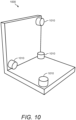
- various sensors 1010 could be disposed in a three-dimensional L-bracket configuration.
- Figs. 9 and 10 represent just two of many different potential sensor arrangements and geometries that may be utilized.
- the various sensors discussed herein that may be arranged in an array to determine a radiometric center of a radiation source that may be the same sensor(s) that measure the time-activity curve (TAC) discussed above.
- the sensors may be utilized to detect an infiltration, measure the time-activity curve at the injection/infiltration site, and even measure the magnitude of the infiltration so as to yield information about the SUV, for example, of an area of interest (e.g. tumor) ultimately measured by a nuclear imaging device (e.g., PET scan) and any correction factor that may need to be applied in view of, for example, an imperfect injection of radiotracer.
- the system may utilize arrays of sensors in combination with other estimation techniques to, for example, quantify and/or measure the magnitude and/or location/size of a radioactive area of interest.
- an area of interest 1101 which may contain a volume of radioactive source material 1103, may be surrounded by a one or a plurality of sensors 1110, forming a sensor array.
- the area of interest 1101 may be within, for example, a patient 1160 (e.g., an infiltrated radiopharmaceutical injection, a tumor being treated with radiopharmaceuticals, an organ desired to be dosed with a precise amount of radiopharmaceutical, etc.), but may more generically be any volume that may include radioactive material, whether located in a body, within some other container/vessel, or standing alone.
- the sensor(s) 1110 may be positioned outside the body of patient 1160 in various geometries relative to the area of interest 1101.
- the array of sensors 1110 may include any number of sensors, including in some embodiments as few as one or two, or as many as four, eight, ten, twenty, thirty, fifty, one-hundred, or more or anywhere in between. Further, each of the plurality of sensors 1110 that make up the array may be identical sensors to one another, or one or more may have unique characteristics relative to one or more other of the sensors 1110. Such distinguishing characteristics may include, but are not limited to, different shielding configurations, different energy threshold settings for detection, different size/shape for given locations or applications, etc. Other varying characteristics may also be utilized, some of which are discussed in greater detail elsewhere in this disclosure.
- each sensor 1110 may detect particles/energy emitted from the radioactive area of interest 1103.
- the sensors 1110 may detect the emitted particles as discussed hereinabove (e.g., through use of scintillation material that emits light when impacted with radioactive particles (e.g., alpha particles, beta particles, or the like) in the sensor and circuitry capable of counting the number of "hits" per unit time).
- radioactive particles e.g., alpha particles, beta particles, or the like
- the array of sensors 1110 may be arranged in any desired geometry relative to each other and relative to the area of interest 1101. In some embodiments, it may be advantageous to utilize a known geometry of sensors, and it may be further advantageous to arrange the sensors 1110 such that the location of each sensor 1110 may be known relative to each of the other sensors 1110 in the array.
- the radioactive activity expected at a given location e.g., at the location of a specific sensor 1110 given certain information, including for example a known amount of radioactive material centered about a known point in space. For example, if the radiometric center, and amount and type of radioactive material is known, and information about the density and composition of the material through which the emitted particles will pass to reach the sensor 1110 (e.g., water, tissue, bone, etc.), one may determine a likelihood that a particle emitted from the radiation source would be detected at a given point in space. Using these techniques, a set of expected measurements can be generated for radioactive sources of various magnitudes, locations, and volumes.
- measurements of activity taken at various points in space relative to a source of radioactive material may be utilized to estimate characteristics about the radioactive material source itself, for example, magnitude, location, volume, etc.
- activity at various locations about a radioactive source may be measured as a function of time. Then, knowing the likelihood of measuring the activity actually measured relative to radioactive sources of various magnitudes and locations, a least squares regression analysis may be used to estimate the magnitude, location, and/or volume of the actual radioactive material source.
- an accurate determination of the amount of radioactive material present can be determined (i.e., the magnitude), and the radiometric center of the radioactive material (i.e., location), and/or distribution of radioactive material (i.e., size of the source of radioactive material) may be determined.
- the system 1100 may assume the presence of a "blob" of radioactive material (e.g., radioactive area of interest 1103) positioned relative to the array made of sensors 1110.
- the radioactive material's location and magnitude may be unknown, but the radioactive material emits radioactive energy/particles and/or decays into other particles/energy (e.g., alpha particles, beta particles, x-rays, gamma rays, positrons etc.) that may be measured by each of the sensors 1110.
- each sensor 1110 may detect those particles that intercept it.
- the system may eliminate unwanted "hits” (e.g., deflected particles), and utilize knowledge of the material through which the particles traveled (i.e., water, bone, etc.) to gain an understanding about the magnitude and/or volume (among other things) of the radioactive source.
- unwanted "hits” e.g., deflected particles
- the material through which the particles traveled i.e., water, bone, etc.
- the least squares regression analysis can be applied to find the magnitude (A), mean location ( ⁇ ) and standard deviation ( ⁇ ) of the radioactive source which minimizes the error between actual counts (c n ) and estimated counts ( ⁇ n ) associated with the various possibilities of radioactive sources.
- the system or method may assume a Gaussian distribution of the radioactive material of interest, but other distributions are possible.
- One drawback to this technique may be that the standard deviation of the distribution is sometimes difficult to determine accurately.
- the counts or "hits" measured by an array made of sensors 1110 may be the same for a collection of radioactive material distributed over a first volume as it would for a collection of the same amount of radioactive material distributed over a second volume.
- the magnitude of the source i.e., how much radioactive material is present
- radiometric center of the source i.e., the location about which the radioactive source is centered
- the volume of space that the source occupies may be more difficult to estimate according to some techniques.
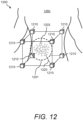
- a volume of interest 1201 may be defined and divided into a plurality of three-dimensional "voxels" (analogous to two-dimensional pixels, see Fig. 13 below). In some embodiments these voxels may be of uniform size and shape, while other embodiments may include voxels of varying size, shape, arrangement, etc.
- Within volume of interest 1201 may lie a radioactive area of interest 1203 of unknown magnitude, location, and volume. Spaced about the volume of interest 1201 may be a plurality of sensors 1210 forming a sensor array.
- each of the sensors 1210 may be positioned proximate a known location relative to the plurality of other sensors 1210.
- the sensors 1210 may be arranged at random known locations about the volume of interest 1201, or in preferred embodiments, may be positioned in mathematically advantageous geometries about the volume of interest 1201, including for example, in triangular, cubic, hemispherical or spherical orientations about the volume of interest 1201, among others. In some embodiments, the arrangements may be symmetrical. In the exemplary embodiment illustrated in Fig. 12 , the sensors are arranged in a substantially cubic configuration about area of interest 1201. It should also be understood that in some embodiments, the relative locations of sensors in space may change over time, and techniques could be employed to measure or otherwise determine the relative positions of the plurality of sensors 1210 at each time t.
- a system for estimating the magnitude, location, and volume of a radioactive area within a volume of interest may utilize an estimation method known as Maximum Likelihood Expectation Maximization (MLEM).
- MLEM Maximum Likelihood Expectation Maximization
- MLEM methods may be used to calculate a probability for each cell or pixel 1305 that a particle 1320 having a certain energy measured at a given location (i.e., the location of one of the sensors 1310) originated from each particular cell 1305.
- a probability may be determined that a particle 1320 originating from each cell 1305 would arrive at the location of the sensor 1310.
- probabilities for each voxel in a three-dimensional space e.g., volume of interest 1201) can be determined.
- a sensor e.g., sensor 1310
- Sensor 1310 may receive a "hit" from a particle 1320 emitted by the radioactive material located within the area of interest 1301.
- particle 1320 measured by sensor 1310 may have originated from any one of the pixels 1305.
- Particles released from radioactive material travel in random directions from their source, and therefore there is only a chance that any particular particle (e.g., particle 1320) will travel in the direction of a given sensor (e.g., sensor 1310). Further, the greater the distance between the source of the particle 1320 and the sensor 1310, the more likely it is that the particle 1320 will collide with some intervening material (e.g., water molecule, bone, etc.) and scatter to a different trajectory. When scattered, the particles lose energy, and therefore it is possible to calibrate the sensors to disregard scattered particles that may be received at a sensor, if desired, as counting scattered particles may introduce error.
- intervening material e.g., water molecule, bone, etc.
- the probability that a sensor 1310 is hit by a particle 1320 that originated in cell B may be lower, for example, than the probability that the particle 1320 originated in cell A.
- the physical distance between cell B and the sensor 1310 is greater than the distance between cell A and the sensor 1310, thereby not only reducing the "solid angle" created by the sensor with respect to the pixel, but also introducing a greater chance that the particle will be scattered from its original trajectory by intervening material.
- the system may determine a set of such probabilities of a particle "hitting" a sensor 1310 for each pixel 1305, and may determine such sets relative to each sensor 1310 for each pixel 1305.
- the probability that a particle 1220 counted by sensor 1210 originated from a relatively close voxel within area of interest 1201 is greater than a probability that particle 1220 originated from a relatively distant voxel in area of interest 1201.
- a set of probabilities for each voxel may be determined for each sensor. This information may be used to generate, or may itself be characterized as, a set of expected signal data associated with radioactive sources of various magnitudes, locations, and/or volumes.
- the system 1200 may be used to take actual measurements of "hits” per unit time observed at each sensor 1210 and estimate, among other things, the magnitude, location, and/or volume of a radioactive source.
- each sensor 1210 should register some number of "hits” if a sufficient amount of radioactive material is present within volume of interest 1201.
- Each "hit” at each sensor 1210 corresponds to a set of probabilities across the voxels 1205 in the volume of interest 1201 corresponding to the likelihood that the particle (e.g., 1220) intercepting a particular sensor 1210 originated in each voxel 1205.
- the system may analyze the sets of probabilities for each "hit” at each sensor 1210 and iterate over time to determine the most likely distribution of radioactive material 1203 within the volume of interest 1201 that would generate the "hits" observed.
- the system may also iterate over various energy levels, providing additional detail.
- Such configurations may also shorten the time and/or reduce the number of calculations required to achieve acceptable iterative convergence.
- Various distributions of voxel size may also be utilized, such that smaller voxels are utilized closer to and within the radioactive source material 1203 and larger voxels are utilized elsewhere, for example.
- a concentric-cubic configuration may be used, where a first set of sensors 1410 may be positioned at each of eight points on a first, inner cube surrounding the area of interest 1401, and a second set of sensors 1410 may be positioned at each of eight points on a second, outer cube surrounding the same area of interest 1201. Proximate each of the eight known points 1430 positioned about the volume of interest 1401, two sensors 1410 may then be provided, for a total of sixteen sensors in the system.
- each fixed location 1430 may include more than two sensors 1410 if desired (e.g., a third cube of greater dimensions), and/or any number of fixed locations 1430 may be utilized (including for example, one, two, four, eight, sixteen, twenty-four, or more, or any number in between, as desired).
- Utilizing two or more sensors 1410 at each location 1430 may have the advantage of aiding, among other things, an iterative convergence. More particularly, by having a second sensor 1410 slightly farther away from the source of radioactive material 1403 relative to the first sensor 1410 at each location 1430, they system may more efficiently arrive at an iterative convergence.
- distinguishable radioactive characteristics e.g., different energy levels, different uptake rates, etc.
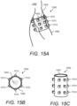
- a plurality of sensors 1510 may be arranged in a substantially cylindrical array to form, for example a cuff 1550.
- Cuff 1550 may be sized to fit, for example, around a portion of a patient's body, for example, a patient's arm 1560.
- cuff 1550 may be positioned about, for example, the location where a patient is or was injected with a radiopharmaceutical or the like.
- cuff 1550 may include a deformable transition layer 1555 that may be utilized to maintain a consistent or otherwise known material composition and/or density between a radioactive source 1503 and the sensors 1510, such as for example, to substantially eliminate air gaps.
- the transition layer 1555 may include water, saline, and/or various other gels or materials.
- the materials may be substantially similar in density to human tissue and/or bone.
- the sensors 1510 of cuff 1550 may also be arranged to provide for substantially "stacked" sensors at various locations on cuff 1550.
- the plurality of sensors 1510 may be arranged to have a first, inner substantially cylindrical configuration and a second, outer substantially cylindrical configuration, thereby providing for two or more sensors 1510 proximate a plurality of desired locations, with one of the sensors 1510 being relatively farther away from the source 1503 than another sensor 1510.
- the system 1500 could be used according to some or all of the methods taught hereinabove to estimate the magnitude, location, and/or volume of the infiltrated radioactive material in the patient.
- the system may also be utilized, in some embodiments, to provide estimates of the magnitude, location, and volume over time, thereby providing critical information to healthcare providers regarding, among many other things, the rate at which radioactive material is being introduced into the bloodstream and therefore affecting, for example, nuclear imaging, and to quantify the patient's tissue exposure to the infiltrated radiation at or around the injection site, to name just a few.
- a larger cuff-like configuration 1650 may be utilized to surround the torso or pelvic region of a patient 1260, for example.
- Such arrangements may enable users to estimate, for example, radiopharmaceutical uptake in a tumor or organ (i.e. organ dosimetry) in the body.
- any arrangement of sensors may be used, and therefore other configurations of sensors may be utilized as needed to fit the nature of the area to be measured. For example, a horseshoe figuration, a flexible sheet configuration, or any other.
- a plurality of sensors 1710 may be arranged in a helmet-like article 1750 such that the sensors 1710 may be arranged about a patient's head 1760.
- the sensors 1710 may be arranged in any manner about the helmet 1750, including in those several configurations discussed herein.
- the sensors 1710 may be disposed about the helmet 1750 in a generally hemispherical configuration and may in some embodiments also include two sensors 1710 at each measurement location 1730.
- helmet 1750 may include a first set of sensors 1710 disposed in a first hemispherical configuration, and a second set of sensors 1710 disposed in a second hemispherical configuration, with the second hemispherical configuration having a slightly larger radius than the first. Accordingly, in some embodiments, there may be two (or more) sensors 1710 about a plurality of desired locations 1730 where one sensor 1710 at each location 1730 is slightly farther away from source 1703 than a second sensor 1710.
- the helmet 1750 may also include a transition layer similar to layer 1555 in Fig. 15 comprising material(s) of known composition and/or density (e.g., water, saline, or gel(s) having a density and other properties similar to that of brain tissue, other tissue, bone (e.g., skull), etc., as desired), thereby eliminating air gaps that could, in some circumstances, complicate the estimations and/or introduce undesirable error.
- a transition layer similar to layer 1555 in Fig. 15 comprising material(s) of known composition and/or density (e.g., water, saline, or gel(s) having a density and other properties similar to that of brain tissue, other tissue, bone (e.g., skull), etc., as desired), thereby eliminating air gaps that could, in some circumstances, complicate the estimations and/or introduce undesirable error.
- material(s) of known composition and/or density e.g., water, saline, or gel(s) having a density and other properties similar to that of brain
- the relative distance between sensors may initially be unknown given the need to modify the cuff 1550, 1650 or helmet 1750 to fit the various sizes and shapes of patients presented.
- the systems and methods taught herein may be modified to introduce known radioactive elements at known locations. For example, relatively small doses of cesium, for example, may be introduced at a known location, from which the relative locations of each sensor may be determined by the system.
- known amounts of cesium may be introduced to determine the specific density of a patient's body through which the particles released from a radiopharmaceutical may travel.
- determining reliable estimates of one or more of the magnitude, location, and/or volume of a radioactive source material in the body it may be possible to, among many other things, evaluate treatment efficacy, make clinical decisions or diagnoses, identify or eliminate medical conditions, compare different areas of the body (e.g., different hemispheres of the bran) and make clinical decisions and/or diagnoses based on such measurements and/or by comparing such measurements to past measurements of the patient and/or measurements of the general population, among many other things.
- the systems and methods taught herein are expected not only to provide such estimates, but to use such estimates to aid clinicians in their diagnosis and treatment, and even suggest or determine appropriate clinical decisions and/or diagnosis.
Landscapes
- Health & Medical Sciences (AREA)
- Life Sciences & Earth Sciences (AREA)
- Engineering & Computer Science (AREA)
- Medical Informatics (AREA)
- Physics & Mathematics (AREA)
- High Energy & Nuclear Physics (AREA)
- Molecular Biology (AREA)
- Nuclear Medicine, Radiotherapy & Molecular Imaging (AREA)
- Optics & Photonics (AREA)
- Biomedical Technology (AREA)
- General Health & Medical Sciences (AREA)
- Animal Behavior & Ethology (AREA)
- Public Health (AREA)
- Biophysics (AREA)
- Pathology (AREA)
- Radiology & Medical Imaging (AREA)
- Heart & Thoracic Surgery (AREA)
- Surgery (AREA)
- Veterinary Medicine (AREA)
- General Physics & Mathematics (AREA)
- Spectroscopy & Molecular Physics (AREA)
- Vascular Medicine (AREA)
- Dentistry (AREA)
- Oral & Maxillofacial Surgery (AREA)
- Nuclear Medicine (AREA)
- Measurement Of Radiation (AREA)
Claims (8)
- Procédé de détermination ex vivo et en temps réel sur une période de temps d'un ou plusieurs de l'ampleur, de l'emplacement et du volume d'une matière radioactive dans le corps en mesurant un rayonnement qui décroît in vivo émis par un sujet, le procédé comprenant :(i) la pose d'un ou plusieurs capteurs de mesure de rayonnement ex vivo (11) à proximité d'une zone d'intérêt sur un patient ;(ii) la détection du rayonnement sur une période de temps souhaitée et la production de données de signal associées à la période de temps souhaitée ;(iii) l'amplification des données de signal à l'aide d'un amplificateur de signal en communication fonctionnelle avec le capteur de rayonnement, le capteur de mesure comportant au moins une sortie de capteur pour ces données de signal amplifiées, et la sortie des données de signal amplifiées ;(iv) le traitement des données de signal amplifiées à l'aide d'un processeur informatique (22) en communication opérationnelle avec une mémoire non transitoire et la sortie du capteur de mesure (11) en exécutant les étapes consistant à :(a) recevoir les données de signal amplifiées associées à la période de temps souhaitée ;(b) comparer les données de signal amplifiées à un ensemble de données de signal espérées pour des sources radioactives ayant des ampleurs, des emplacements et des volumes divers ;(c) déterminer, sur la base de la comparaison des données de signal amplifiées à un ensemble de données de signal espérées pour des sources radioactives ayant des ampleurs, des emplacements et des volumes divers, un ou plusieurs d'une ampleur, d'un emplacement et d'un volume de la source radioactive dans le corps au cours de la période de temps souhaitée en ajustant les données de signal amplifiées à l'ensemble le plus vraisemblable de données de signal espérées.
- Procédé selon la revendication 1, dans lequel une méthode de maximisation de l'espérance du maximum de vraisemblance est utilisée pour l'ajustement à l'ampleur, à l'emplacement et au volume les plus vraisemblables de la source radioactive dans le corps.
- Procédé selon la revendication 1, comprenant en outre l'étape consistant à déterminer une dose de radioactivité reçue par une zone de tissu proche de l'emplacement de la source radioactive.
- Procédé selon la revendication 1, comprenant en outre l'étape consistant à utiliser les un ou plusieurs de l'ampleur, de l'emplacement et du volume d'une source radioactive dans le corps qui ont été déterminés pour prendre une décision clinique.
- Procédé selon la revendication 1, dans lequel un réseau comprenant deux ou plus des capteurs de mesure de rayonnement ex vivo est utilisé.
- Procédé selon la revendication 5, dans lequel les deux capteurs ou plus sont disposés à proximité d'un ou plusieurs emplacements de mesure souhaités, et en outre dans lequel chaque emplacement de mesure souhaité comprend au moins un premier capteur disposé relativement plus près de la source radioactive qu'un deuxième capteur.
- Procédé selon la revendication 1, dans lequel un ou plusieurs d'une ampleur, d'un emplacement ou d'un volume sont déterminés pour deux sources de rayonnement ou plus dans le corps.
- Procédé selon la revendication 7, comprenant en outre l'étape consistant à comparer les un ou plusieurs de l'ampleur, de l'emplacement et du volume des deux sources radioactives ou plus qui ont été déterminés, et à prendre une décision clinique sur la base de la comparaison.
Applications Claiming Priority (3)
| Application Number | Priority Date | Filing Date | Title |
|---|---|---|---|
| US201962828033P | 2019-04-02 | 2019-04-02 | |
| US16/837,187 US12357250B2 (en) | 2019-04-02 | 2020-04-01 | System and method of using temporal measurements of localized radiation to estimate the magnitude, location, and volume of radioactive material in the body |
| PCT/US2020/026347 WO2020206092A1 (fr) | 2019-04-02 | 2020-04-02 | Système et procédé d'utilisation de mesures temporelles de rayonnement localisé pour estimer l'amplitude, l'emplacement et le volume de matériau radioactif dans le corps |
Publications (3)
| Publication Number | Publication Date |
|---|---|
| EP3946063A1 EP3946063A1 (fr) | 2022-02-09 |
| EP3946063A4 EP3946063A4 (fr) | 2022-12-07 |
| EP3946063B1 true EP3946063B1 (fr) | 2024-10-16 |
Family
ID=72662101
Family Applications (1)
| Application Number | Title | Priority Date | Filing Date |
|---|---|---|---|
| EP20784501.7A Active EP3946063B1 (fr) | 2019-04-02 | 2020-04-02 | Procédé d'utilisation de mesures temporelles de rayonnement localisé pour estimer l'amplitude, l'emplacement et le volume de matériau radioactif dans le corps |
Country Status (7)
| Country | Link |
|---|---|
| US (1) | US12357250B2 (fr) |
| EP (1) | EP3946063B1 (fr) |
| JP (1) | JP7652708B2 (fr) |
| AU (1) | AU2020256211B2 (fr) |
| DK (1) | DK3946063T3 (fr) |
| ES (1) | ES3008557T3 (fr) |
| WO (1) | WO2020206092A1 (fr) |
Families Citing this family (4)
| Publication number | Priority date | Publication date | Assignee | Title |
|---|---|---|---|---|
| US12357250B2 (en) | 2019-04-02 | 2025-07-15 | Lucerno Dynamics, Llc | System and method of using temporal measurements of localized radiation to estimate the magnitude, location, and volume of radioactive material in the body |
| CN113647969B (zh) * | 2021-09-16 | 2023-07-07 | 上海联影医疗科技股份有限公司 | 一种放射性示踪剂成分分析方法和系统 |
| WO2023137118A2 (fr) * | 2022-01-12 | 2023-07-20 | Lucerno Dynamics, Llc | Système et procédés de mesure de dosimétrie d'extravasation spécifique à un patient |
| EP4463717A4 (fr) * | 2022-01-12 | 2026-02-25 | Lucerno Dynamics Llc | Système et procédés de mesure de dosimétrie d'extravasation spécifique à un patient |
Family Cites Families (48)
| Publication number | Priority date | Publication date | Assignee | Title |
|---|---|---|---|---|
| US4095107A (en) * | 1976-04-15 | 1978-06-13 | Sebastian Genna | Transaxial radionuclide emission camera apparatus and method |
| FR2552233B1 (fr) | 1983-09-16 | 1987-06-26 | Labo Electronique Physique | Dispositif de mesure de radiations et camera a scintillation equipee d'un tel dispositif |
| US4692890A (en) | 1984-05-29 | 1987-09-08 | Siemens Gammasonics, Inc. | Method and integrator circuit for integrating signals, in particular for scintillation gamma camera |
| US4682604A (en) | 1985-02-25 | 1987-07-28 | The Regents Of The University Of California | Coincidence counting emission tomographic probe: method and apparatus |
| US5007427A (en) | 1987-05-07 | 1991-04-16 | Capintec, Inc. | Ambulatory physiological evaluation system including cardiac monitoring |
| DE3769529D1 (de) | 1986-07-09 | 1991-05-29 | Philips Nv | Szintillationskamera. |
| US5301673A (en) * | 1991-11-18 | 1994-04-12 | Massachusetts General Hospital | Ambulatory clearance function monitor |
| US5309357A (en) | 1992-01-28 | 1994-05-03 | Independent Scintillation Imaging Systems (Isis) Inc. | Scintillation data collecting apparatus and method |
| FR2704655B1 (fr) | 1993-04-28 | 1995-07-21 | Sodern | Mini-caméra pour la détection rapprochée d'un rayonnement nucléaire émis par un radio-isotope et application à l'assistance chirurgicale. |
| US5583343A (en) | 1995-07-25 | 1996-12-10 | Associated Universities, Inc. | Flexible nuclear medicine camera and method of using |
| FR2738693B1 (fr) | 1995-09-12 | 1997-10-10 | Commissariat Energie Atomique | Systeme de traitement d'impulsions provenant de l'interaction d'une particule gamma avec un detecteur de rayonnement cdte |
| US6638234B2 (en) * | 1998-03-03 | 2003-10-28 | Senorx, Inc. | Sentinel node location and biopsy |
| US6448544B1 (en) | 1998-06-08 | 2002-09-10 | Brandeis University | Low noise, high resolution image detection system and method |
| US6402689B1 (en) | 1998-09-30 | 2002-06-11 | Sicel Technologies, Inc. | Methods, systems, and associated implantable devices for dynamic monitoring of physiological and biological properties of tumors |
| JP4536212B2 (ja) * | 2000-05-24 | 2010-09-01 | 浜松ホトニクス株式会社 | Pet装置 |
| US8565860B2 (en) | 2000-08-21 | 2013-10-22 | Biosensors International Group, Ltd. | Radioactive emission detector equipped with a position tracking system |
| JP4454840B2 (ja) | 2000-12-25 | 2010-04-21 | 株式会社東芝 | 放射線計装システムおよびその健全性診断方法ならびに放射線計測方法 |
| US20090226915A1 (en) | 2001-01-24 | 2009-09-10 | Health Discovery Corporation | Methods for Screening, Predicting and Monitoring Prostate Cancer |
| US7011814B2 (en) | 2001-04-23 | 2006-03-14 | Sicel Technologies, Inc. | Systems, methods and devices for in vivo monitoring of a localized response via a radiolabeled analyte in a subject |
| US7557353B2 (en) | 2001-11-30 | 2009-07-07 | Sicel Technologies, Inc. | Single-use external dosimeters for use in radiation therapies |
| ES2527310T3 (es) * | 2002-01-25 | 2015-01-22 | University Of Wollongong | Método y aparato para dosimetría en tiempo real |
| AU2003227067A1 (en) | 2002-03-15 | 2003-09-29 | Pharmacia Italia S.P.A. | Method for estimating or predicting the anti-tumor activity of a compound and for estimating or predicting the tumor growth in mammals |
| US7095439B2 (en) | 2002-04-04 | 2006-08-22 | Motorola, Inc. | Image sensor circuit and method |
| EP1566664B1 (fr) | 2002-11-26 | 2014-03-12 | ARKRAY, Inc. | Capteur de lumiere, mecanisme de detection et mecanisme de mesure de la lumiere utilises dans un dispositif d'analyse |
| US8068896B2 (en) | 2005-02-25 | 2011-11-29 | Intramedical Imaging, Llc | Detection of radiation labeled sites using a radiation detection probe or camera incorporating a solid state photo-multiplier |
| WO2007016367A2 (fr) | 2005-07-29 | 2007-02-08 | Bayer Healthcare Llc | Procedes, kits, systemes et bases de donnees relatifs a des maladies neoplasiques |
| US8568285B2 (en) | 2005-12-05 | 2013-10-29 | Hampton University | Apparatus and method for external beam radiation distribution mapping |
| WO2007131536A1 (fr) | 2006-05-11 | 2007-11-22 | Advanced Accelerator Applications | Méthode et dispositif de détection, de localisation et/ou d'analyse d'une (de) source(s) radioactive(s) dans un materiel, par exemple un tissu biologique |
| WO2007131485A1 (fr) | 2006-05-16 | 2007-11-22 | Silicon Instruments Gmbh | Système pourvu d'une sonde gamma médicale, module optique et ensemble correspondant |
| WO2007140352A2 (fr) | 2006-05-26 | 2007-12-06 | Invitrogen Corporation | Membrane plasmatique et biomarqueurs de cancer sécrétés |
| US7711409B2 (en) | 2006-10-04 | 2010-05-04 | Hampton University | Opposed view and dual head detector apparatus for diagnosis and biopsy with image processing methods |
| EP2139541B1 (fr) | 2007-01-01 | 2018-04-11 | Bayer Healthcare LLC | Systèmes permettant la génération, la préparation, le transport et l'administration radiopharmaceutiques intégrés |
| TWI417110B (zh) | 2007-11-30 | 2013-12-01 | Iner Aec Executive Yuan | 檢測肝殘餘功能之醣質醫學影像分子造影劑 |
| ES2457534T3 (es) | 2008-05-30 | 2014-04-28 | The University Of North Carolina At Chapel Hill | Perfiles de expresión génica para predecir desenlaces en cáncer de mama |
| EP2310877A2 (fr) | 2008-06-11 | 2011-04-20 | Innovative American Technology Inc. | Détecteur de neutrons haute performance présentant une diaphonie gamma proche de zéro |
| FR2934698B1 (fr) | 2008-08-01 | 2011-11-18 | Commissariat Energie Atomique | Procede de prediction pour le pronostic ou le diagnostic ou la reponse therapeutique d'une maladie et notamment du cancer de la prostate et dispositif permettant la mise en oeuvre du procede. |
| GB2468474B (en) | 2008-12-09 | 2013-12-25 | Thermo Electron Ltd | Beta radiation monitor and method |
| JP2011163966A (ja) | 2010-02-10 | 2011-08-25 | Toshiba Corp | 医用画像診断装置及び放射線量算出用制御プログラム |
| US9002438B2 (en) | 2012-05-30 | 2015-04-07 | Lucerno Dynamics | System for the detection of gamma radiation from a radioactive analyte |
| US9939533B2 (en) * | 2012-05-30 | 2018-04-10 | Lucerno Dynamics, Llc | System and method for the detection of gamma radiation from a radioactive analyte |
| JP6124216B2 (ja) | 2013-10-30 | 2017-05-10 | 国立研究開発法人量子科学技術研究開発機構 | ヘルメット型pet装置 |
| WO2015196208A2 (fr) * | 2014-06-20 | 2015-12-23 | The General Hospital Corporation | Sondes d'imagerie ciblées sur le collagène |
| US10978284B2 (en) | 2015-03-06 | 2021-04-13 | Micromass Uk Limited | Imaging guided ambient ionisation mass spectrometry |
| JP6377574B2 (ja) | 2015-04-03 | 2018-08-22 | ルサーノ・ダイナミクス | 放射線検体からのガンマ線を検出するシステムおよび方法 |
| JP7204364B2 (ja) | 2018-07-25 | 2023-01-16 | キヤノン株式会社 | 梱包体 |
| US12357250B2 (en) | 2019-04-02 | 2025-07-15 | Lucerno Dynamics, Llc | System and method of using temporal measurements of localized radiation to estimate the magnitude, location, and volume of radioactive material in the body |
| US20210015434A1 (en) | 2019-04-02 | 2021-01-21 | Lucerno Dynamics, Llc | System and method of using temporal measurements of localized radiation to estimate the magnitude, location, and volume of radioactive material in the body |
| US20210128082A1 (en) | 2019-11-06 | 2021-05-06 | GE Precision Healthcare LLC | Methods and systems for body contour profiles |
-
2020
- 2020-04-01 US US16/837,187 patent/US12357250B2/en active Active
- 2020-04-02 DK DK20784501.7T patent/DK3946063T3/da active
- 2020-04-02 JP JP2021560415A patent/JP7652708B2/ja active Active
- 2020-04-02 WO PCT/US2020/026347 patent/WO2020206092A1/fr not_active Ceased
- 2020-04-02 EP EP20784501.7A patent/EP3946063B1/fr active Active
- 2020-04-02 ES ES20784501T patent/ES3008557T3/es active Active
- 2020-04-02 AU AU2020256211A patent/AU2020256211B2/en active Active
Also Published As
| Publication number | Publication date |
|---|---|
| ES3008557T3 (en) | 2025-03-24 |
| WO2020206092A1 (fr) | 2020-10-08 |
| JP7652708B2 (ja) | 2025-03-27 |
| US20200315558A1 (en) | 2020-10-08 |
| AU2020256211A1 (en) | 2021-11-25 |
| US12357250B2 (en) | 2025-07-15 |
| DK3946063T3 (en) | 2024-11-18 |
| EP3946063A1 (fr) | 2022-02-09 |
| JP2022523881A (ja) | 2022-04-26 |
| AU2020256211B2 (en) | 2025-10-09 |
| EP3946063A4 (fr) | 2022-12-07 |
Similar Documents
| Publication | Publication Date | Title |
|---|---|---|
| EP3946063B1 (fr) | Procédé d'utilisation de mesures temporelles de rayonnement localisé pour estimer l'amplitude, l'emplacement et le volume de matériau radioactif dans le corps | |
| Zanzonico | Principles of nuclear medicine imaging: planar, SPECT, PET, multi-modality, and autoradiography systems | |
| US20250213205A1 (en) | System and method of using temporal measurements of localized radiation to estimate the magnitude, location, and volume of radioactive material in the body | |
| US10820880B2 (en) | Method and apparatus for sensitivity calibration | |
| US11850092B2 (en) | Dual modality endocavity biopsy imaging system and method | |
| US9529100B2 (en) | Positron emission tomography detector and positron emission tomography system using same | |
| CN108209958A (zh) | 一种归一化校正因子的确定、获取方法及医学成像方法 | |
| EP2083871B1 (fr) | Determination d'une distribution d'agents radioactifs dans un sujet | |
| WO2015107179A1 (fr) | Applicateur très peu invasif pour dosimétrie de rayonnement in situ | |
| D'Asseler | Advances in SPECT imaging with respect to radionuclide therapy | |
| US20140142424A1 (en) | Dual modality endocavity biopsy imaging system and method | |
| US12422570B2 (en) | System and methods for measuring patient-specific extravasation dosimetry | |
| US7554088B2 (en) | Method for positron emission imaging | |
| EP4463717A2 (fr) | Système et procédés de mesure de dosimétrie d'extravasation spécifique à un patient | |
| CN111265787A (zh) | 适应于bnct系统的含硼-10药物浓度分布测量装置和方法 | |
| Raylman et al. | Investigation of a dedicated, high resolution PET/CT scanner for staging and treatment planning of head and neck cancer | |
| Baldassi | Design and evaluation of a clinical organ-targeted positron emission tomography camera | |
| CN101534866A (zh) | 用于测定受试者中放射性试剂的分布的系统 | |
| Bienenstock et al. | The effect of object size on the sensitivity of single photon emission computed tomography: comparison of two CZT cardiac cameras and an Anger scintillation camera | |
| Li et al. | Equipment for Imaging and Mechanism of Radiation Protection | |
| Bebbington | Optimal SPECT Detector Configuration for Myocardial Perfusion Scintigraphy in Patients with Small Body Habitus | |
| Graham | Instrumentation-Nuclear Medicine and PET | |
| Tuncel | Assessment of patient dose in medical processes by in-vivo dose measuring devices: A review | |
| Pavlopoulos | Design and performance evaluation of a new high-resolution small animal PET scanner using Monte Carlo techniques | |
| González et al. | Inter-crystal scatter in positron emission tomography: Identification techniques and effects on reconstructed images for AX-PET demonstrator |
Legal Events
| Date | Code | Title | Description |
|---|---|---|---|
| STAA | Information on the status of an ep patent application or granted ep patent |
Free format text: STATUS: THE INTERNATIONAL PUBLICATION HAS BEEN MADE |
|
| PUAI | Public reference made under article 153(3) epc to a published international application that has entered the european phase |
Free format text: ORIGINAL CODE: 0009012 |
|
| STAA | Information on the status of an ep patent application or granted ep patent |
Free format text: STATUS: REQUEST FOR EXAMINATION WAS MADE |
|
| 17P | Request for examination filed |
Effective date: 20211001 |
|
| AK | Designated contracting states |
Kind code of ref document: A1 Designated state(s): AL AT BE BG CH CY CZ DE DK EE ES FI FR GB GR HR HU IE IS IT LI LT LU LV MC MK MT NL NO PL PT RO RS SE SI SK SM TR |
|
| DAV | Request for validation of the european patent (deleted) | ||
| DAX | Request for extension of the european patent (deleted) | ||
| A4 | Supplementary search report drawn up and despatched |
Effective date: 20221107 |
|
| RIC1 | Information provided on ipc code assigned before grant |
Ipc: A61B 6/03 20060101ALN20221031BHEP Ipc: G01T 1/164 20060101ALI20221031BHEP Ipc: G01T 1/161 20060101ALI20221031BHEP Ipc: A61B 6/00 20060101AFI20221031BHEP |
|
| GRAP | Despatch of communication of intention to grant a patent |
Free format text: ORIGINAL CODE: EPIDOSNIGR1 |
|
| STAA | Information on the status of an ep patent application or granted ep patent |
Free format text: STATUS: GRANT OF PATENT IS INTENDED |
|
| RIC1 | Information provided on ipc code assigned before grant |
Ipc: A61B 6/03 20060101ALN20231214BHEP Ipc: G01T 1/164 20060101ALI20231214BHEP Ipc: G01T 1/161 20060101ALI20231214BHEP Ipc: A61B 6/00 20060101AFI20231214BHEP |
|
| INTG | Intention to grant announced |
Effective date: 20240105 |
|
| RIC1 | Information provided on ipc code assigned before grant |
Ipc: A61B 6/03 20060101ALN20231215BHEP Ipc: G01T 1/164 20060101ALI20231215BHEP Ipc: G01T 1/161 20060101ALI20231215BHEP Ipc: A61B 6/00 20060101AFI20231215BHEP |
|
| GRAJ | Information related to disapproval of communication of intention to grant by the applicant or resumption of examination proceedings by the epo deleted |
Free format text: ORIGINAL CODE: EPIDOSDIGR1 |
|
| STAA | Information on the status of an ep patent application or granted ep patent |
Free format text: STATUS: REQUEST FOR EXAMINATION WAS MADE |
|
| GRAP | Despatch of communication of intention to grant a patent |
Free format text: ORIGINAL CODE: EPIDOSNIGR1 |
|
| STAA | Information on the status of an ep patent application or granted ep patent |
Free format text: STATUS: GRANT OF PATENT IS INTENDED |
|
| INTC | Intention to grant announced (deleted) | ||
| RIC1 | Information provided on ipc code assigned before grant |
Ipc: A61B 6/03 20060101ALN20240430BHEP Ipc: G01T 7/00 20060101ALI20240430BHEP Ipc: A61B 6/50 20240101ALI20240430BHEP Ipc: A61B 6/42 20240101ALI20240430BHEP Ipc: G01T 1/164 20060101ALI20240430BHEP Ipc: G01T 1/161 20060101ALI20240430BHEP Ipc: A61B 6/00 20060101AFI20240430BHEP |
|
| INTG | Intention to grant announced |
Effective date: 20240516 |
|
| RIC1 | Information provided on ipc code assigned before grant |
Ipc: A61B 6/03 20060101ALN20240506BHEP Ipc: G01T 7/00 20060101ALI20240506BHEP Ipc: A61B 6/50 20240101ALI20240506BHEP Ipc: A61B 6/42 20240101ALI20240506BHEP Ipc: G01T 1/164 20060101ALI20240506BHEP Ipc: G01T 1/161 20060101ALI20240506BHEP Ipc: A61B 6/00 20060101AFI20240506BHEP |
|
| GRAS | Grant fee paid |
Free format text: ORIGINAL CODE: EPIDOSNIGR3 |
|
| GRAA | (expected) grant |
Free format text: ORIGINAL CODE: 0009210 |
|
| STAA | Information on the status of an ep patent application or granted ep patent |
Free format text: STATUS: THE PATENT HAS BEEN GRANTED |
|
| AK | Designated contracting states |
Kind code of ref document: B1 Designated state(s): AL AT BE BG CH CY CZ DE DK EE ES FI FR GB GR HR HU IE IS IT LI LT LU LV MC MK MT NL NO PL PT RO RS SE SI SK SM TR |
|
| REG | Reference to a national code |
Ref country code: GB Ref legal event code: FG4D |
|
| REG | Reference to a national code |
Ref country code: CH Ref legal event code: EP Ref country code: DE Ref legal event code: R096 Ref document number: 602020039605 Country of ref document: DE |
|
| REG | Reference to a national code |
Ref country code: IE Ref legal event code: FG4D |
|
| REG | Reference to a national code |
Ref country code: DK Ref legal event code: T3 Effective date: 20241113 |
|
| REG | Reference to a national code |
Ref country code: SE Ref legal event code: TRGR |
|
| REG | Reference to a national code |
Ref country code: NL Ref legal event code: FP |
|
| REG | Reference to a national code |
Ref country code: LT Ref legal event code: MG9D |
|
| REG | Reference to a national code |
Ref country code: AT Ref legal event code: MK05 Ref document number: 1732257 Country of ref document: AT Kind code of ref document: T Effective date: 20241016 |
|
| REG | Reference to a national code |
Ref country code: ES Ref legal event code: FG2A Ref document number: 3008557 Country of ref document: ES Kind code of ref document: T3 Effective date: 20250324 |
|
| PG25 | Lapsed in a contracting state [announced via postgrant information from national office to epo] |
Ref country code: PT Free format text: LAPSE BECAUSE OF FAILURE TO SUBMIT A TRANSLATION OF THE DESCRIPTION OR TO PAY THE FEE WITHIN THE PRESCRIBED TIME-LIMIT Effective date: 20250217 Ref country code: HR Free format text: LAPSE BECAUSE OF FAILURE TO SUBMIT A TRANSLATION OF THE DESCRIPTION OR TO PAY THE FEE WITHIN THE PRESCRIBED TIME-LIMIT Effective date: 20241016 Ref country code: IS Free format text: LAPSE BECAUSE OF FAILURE TO SUBMIT A TRANSLATION OF THE DESCRIPTION OR TO PAY THE FEE WITHIN THE PRESCRIBED TIME-LIMIT Effective date: 20250216 |
|
| PG25 | Lapsed in a contracting state [announced via postgrant information from national office to epo] |
Ref country code: FI Free format text: LAPSE BECAUSE OF FAILURE TO SUBMIT A TRANSLATION OF THE DESCRIPTION OR TO PAY THE FEE WITHIN THE PRESCRIBED TIME-LIMIT Effective date: 20241016 |
|
| PG25 | Lapsed in a contracting state [announced via postgrant information from national office to epo] |
Ref country code: BG Free format text: LAPSE BECAUSE OF FAILURE TO SUBMIT A TRANSLATION OF THE DESCRIPTION OR TO PAY THE FEE WITHIN THE PRESCRIBED TIME-LIMIT Effective date: 20241016 |
|
| PG25 | Lapsed in a contracting state [announced via postgrant information from national office to epo] |
Ref country code: NO Free format text: LAPSE BECAUSE OF FAILURE TO SUBMIT A TRANSLATION OF THE DESCRIPTION OR TO PAY THE FEE WITHIN THE PRESCRIBED TIME-LIMIT Effective date: 20250116 |
|
| PG25 | Lapsed in a contracting state [announced via postgrant information from national office to epo] |
Ref country code: LV Free format text: LAPSE BECAUSE OF FAILURE TO SUBMIT A TRANSLATION OF THE DESCRIPTION OR TO PAY THE FEE WITHIN THE PRESCRIBED TIME-LIMIT Effective date: 20241016 Ref country code: AT Free format text: LAPSE BECAUSE OF FAILURE TO SUBMIT A TRANSLATION OF THE DESCRIPTION OR TO PAY THE FEE WITHIN THE PRESCRIBED TIME-LIMIT Effective date: 20241016 Ref country code: GR Free format text: LAPSE BECAUSE OF FAILURE TO SUBMIT A TRANSLATION OF THE DESCRIPTION OR TO PAY THE FEE WITHIN THE PRESCRIBED TIME-LIMIT Effective date: 20250117 |
|
| PG25 | Lapsed in a contracting state [announced via postgrant information from national office to epo] |
Ref country code: PL Free format text: LAPSE BECAUSE OF FAILURE TO SUBMIT A TRANSLATION OF THE DESCRIPTION OR TO PAY THE FEE WITHIN THE PRESCRIBED TIME-LIMIT Effective date: 20241016 |
|
| PG25 | Lapsed in a contracting state [announced via postgrant information from national office to epo] |
Ref country code: RS Free format text: LAPSE BECAUSE OF FAILURE TO SUBMIT A TRANSLATION OF THE DESCRIPTION OR TO PAY THE FEE WITHIN THE PRESCRIBED TIME-LIMIT Effective date: 20250116 |
|
| PGFP | Annual fee paid to national office [announced via postgrant information from national office to epo] |
Ref country code: NL Payment date: 20250427 Year of fee payment: 6 |
|
| PG25 | Lapsed in a contracting state [announced via postgrant information from national office to epo] |
Ref country code: SM Free format text: LAPSE BECAUSE OF FAILURE TO SUBMIT A TRANSLATION OF THE DESCRIPTION OR TO PAY THE FEE WITHIN THE PRESCRIBED TIME-LIMIT Effective date: 20241016 |
|
| PGFP | Annual fee paid to national office [announced via postgrant information from national office to epo] |
Ref country code: DE Payment date: 20250429 Year of fee payment: 6 |
|
| PGFP | Annual fee paid to national office [announced via postgrant information from national office to epo] |
Ref country code: GB Payment date: 20250428 Year of fee payment: 6 Ref country code: ES Payment date: 20250505 Year of fee payment: 6 Ref country code: DK Payment date: 20250425 Year of fee payment: 6 |
|
| PGFP | Annual fee paid to national office [announced via postgrant information from national office to epo] |
Ref country code: BE Payment date: 20250428 Year of fee payment: 6 Ref country code: IT Payment date: 20250422 Year of fee payment: 6 |
|
| REG | Reference to a national code |
Ref country code: DE Ref legal event code: R097 Ref document number: 602020039605 Country of ref document: DE |
|
| PG25 | Lapsed in a contracting state [announced via postgrant information from national office to epo] |
Ref country code: EE Free format text: LAPSE BECAUSE OF FAILURE TO SUBMIT A TRANSLATION OF THE DESCRIPTION OR TO PAY THE FEE WITHIN THE PRESCRIBED TIME-LIMIT Effective date: 20241016 |
|
| PGFP | Annual fee paid to national office [announced via postgrant information from national office to epo] |
Ref country code: FR Payment date: 20250425 Year of fee payment: 6 |
|
| PGFP | Annual fee paid to national office [announced via postgrant information from national office to epo] |
Ref country code: CH Payment date: 20250501 Year of fee payment: 6 |
|
| PG25 | Lapsed in a contracting state [announced via postgrant information from national office to epo] |
Ref country code: RO Free format text: LAPSE BECAUSE OF FAILURE TO SUBMIT A TRANSLATION OF THE DESCRIPTION OR TO PAY THE FEE WITHIN THE PRESCRIBED TIME-LIMIT Effective date: 20241016 |
|
| PG25 | Lapsed in a contracting state [announced via postgrant information from national office to epo] |
Ref country code: SK Free format text: LAPSE BECAUSE OF FAILURE TO SUBMIT A TRANSLATION OF THE DESCRIPTION OR TO PAY THE FEE WITHIN THE PRESCRIBED TIME-LIMIT Effective date: 20241016 |
|
| PG25 | Lapsed in a contracting state [announced via postgrant information from national office to epo] |
Ref country code: CZ Free format text: LAPSE BECAUSE OF FAILURE TO SUBMIT A TRANSLATION OF THE DESCRIPTION OR TO PAY THE FEE WITHIN THE PRESCRIBED TIME-LIMIT Effective date: 20241016 |
|
| PGFP | Annual fee paid to national office [announced via postgrant information from national office to epo] |
Ref country code: IE Payment date: 20250428 Year of fee payment: 6 |
|
| PGFP | Annual fee paid to national office [announced via postgrant information from national office to epo] |
Ref country code: SE Payment date: 20250507 Year of fee payment: 6 |
|
| PLBE | No opposition filed within time limit |
Free format text: ORIGINAL CODE: 0009261 |
|
| STAA | Information on the status of an ep patent application or granted ep patent |
Free format text: STATUS: NO OPPOSITION FILED WITHIN TIME LIMIT |
|
| 26N | No opposition filed |
Effective date: 20250717 |
|
| PG25 | Lapsed in a contracting state [announced via postgrant information from national office to epo] |
Ref country code: LU Free format text: LAPSE BECAUSE OF NON-PAYMENT OF DUE FEES Effective date: 20250402 |
|
| PG25 | Lapsed in a contracting state [announced via postgrant information from national office to epo] |
Ref country code: MC Free format text: LAPSE BECAUSE OF FAILURE TO SUBMIT A TRANSLATION OF THE DESCRIPTION OR TO PAY THE FEE WITHIN THE PRESCRIBED TIME-LIMIT Effective date: 20241016 |