EP3946077B1 - Crimp-instrument und ladewerkzeug dafür - Google Patents
Crimp-instrument und ladewerkzeug dafür Download PDFInfo
- Publication number
- EP3946077B1 EP3946077B1 EP20795670.7A EP20795670A EP3946077B1 EP 3946077 B1 EP3946077 B1 EP 3946077B1 EP 20795670 A EP20795670 A EP 20795670A EP 3946077 B1 EP3946077 B1 EP 3946077B1
- Authority
- EP
- European Patent Office
- Prior art keywords
- snare
- suture
- loading tool
- handle
- instrument
- Prior art date
- Legal status (The legal status is an assumption and is not a legal conclusion. Google has not performed a legal analysis and makes no representation as to the accuracy of the status listed.)
- Active
Links
Images











Classifications
-
- A—HUMAN NECESSITIES
- A61—MEDICAL OR VETERINARY SCIENCE; HYGIENE
- A61B—DIAGNOSIS; SURGERY; IDENTIFICATION
- A61B17/00—Surgical instruments, devices or methods
- A61B17/04—Surgical instruments, devices or methods for suturing wounds; Holders or packages for needles or suture materials
- A61B17/0487—Suture clamps, clips or locks, e.g. for replacing suture knots; Instruments for applying or removing suture clamps, clips or locks
-
- A—HUMAN NECESSITIES
- A61—MEDICAL OR VETERINARY SCIENCE; HYGIENE
- A61B—DIAGNOSIS; SURGERY; IDENTIFICATION
- A61B17/00—Surgical instruments, devices or methods
- A61B17/04—Surgical instruments, devices or methods for suturing wounds; Holders or packages for needles or suture materials
- A61B17/0469—Suturing instruments for use in minimally invasive surgery, e.g. endoscopic surgery
-
- A—HUMAN NECESSITIES
- A61—MEDICAL OR VETERINARY SCIENCE; HYGIENE
- A61B—DIAGNOSIS; SURGERY; IDENTIFICATION
- A61B17/00—Surgical instruments, devices or methods
- A61B17/04—Surgical instruments, devices or methods for suturing wounds; Holders or packages for needles or suture materials
- A61B17/0485—Devices or means, e.g. loops, for capturing the suture thread and threading it through an opening of a suturing instrument or needle eyelet
-
- A—HUMAN NECESSITIES
- A61—MEDICAL OR VETERINARY SCIENCE; HYGIENE
- A61B—DIAGNOSIS; SURGERY; IDENTIFICATION
- A61B17/00—Surgical instruments, devices or methods
- A61B17/04—Surgical instruments, devices or methods for suturing wounds; Holders or packages for needles or suture materials
- A61B17/0487—Suture clamps, clips or locks, e.g. for replacing suture knots; Instruments for applying or removing suture clamps, clips or locks
- A61B2017/0488—Instruments for applying suture clamps, clips or locks
-
- A—HUMAN NECESSITIES
- A61—MEDICAL OR VETERINARY SCIENCE; HYGIENE
- A61B—DIAGNOSIS; SURGERY; IDENTIFICATION
- A61B90/00—Instruments, implements or accessories specially adapted for surgery or diagnosis and not covered by any of the groups A61B1/00 - A61B50/00, e.g. for luxation treatment or for protecting wound edges
- A61B90/08—Accessories or related features not otherwise provided for
- A61B2090/0817—Spatulas or spatula like extensions
Definitions
- the instrument also includes at least one shaft; one or more receiving faces, each configured to receive one of the one or more suture fasteners; one or more anvils, each of the one or more anvils corresponding to one of the one or more receiving faces; one or more hammers, each of the one or more hammers corresponding to one of the one or more anvils and moveable relative to its corresponding anvil for crimping the one or more suture fasteners therebetween and received in the one or more receiving faces; one or more pusher moveable in a direction substantially parallel to a longitudinal axis of the at least one shaft and configured to engage at least one of the hammer and the anvil for urging the hammer and the anvil together; and a loading tool including a target cover defining one or more snare guides and one or more target cover suture openings, each of which lies at least partially within a corresponding one of the one or more
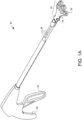
- FIG. 1A is a top-right-distal perspective view of one embodiment of an instrument 20 for crimping suture fasteners having one embodiment of a loading tool 22.
- FIG. 1B is a bottom-right-distal perspective view of the crimping instrument 20 and loading tool 22 of FIG. 1A .
- the loading tool 22 has a target cover 24 and a target tray 26.
- the crimping instrument 20 has a plurality of shafts 28, the distal ends of which each hold a receiving face (not visible in this view, but discussed below) configured to receive a suture fastener.
- the crimping instrument also has a handle 30 which the user can hold and a lever 32 which is moveable relative to the handle 30 for actuating structures within the instrument 20 for crimping the suture fasteners held by the device when desired. The structures which make this possible will be discussed in more detail below.
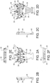
- FIGS. 2A, 2B, 2C, 2D, 2E, and 2F are top, left, right, bottom, distal, and proximal views, respectively, of one embodiment of a target cover 24 from the loading tool 22 of FIG. 1A .
- the target cover 24 defines a plurality of snare guides 34.
- the target cover 24 also defines a plurality of suture openings 36, each of which lies at least partially within a corresponding one of the one or more snare guides 34.
- the target cover 24 further defines a suture clearance slot 38 coupled to (or in communication with) each of the one or more target cover suture openings 36.
- the target cover 24 also has a coupling latch 40.
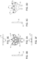
- FIGS. 3A, 3B, 3C, 3D, 3E, and 3F are top, left, right, bottom, distal, and proximal views, respectively, of one embodiment of a target tray 26 from the loading tool 22 of FIG. 1A .
- the target tray 26 defines a plurality of suture openings 42.
- the target tray 26 of this embodiment also defines a plurality of snare channels 44.
- the target tray 26 also has a coupling latch 46.
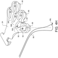
- FIGS. 4A-4P are a series of exploded views which illustrate the assembly of one embodiment of a crimping instrument having a loading tool. Note that there are no FIGS. 4I and 4O to avoid possible confusion with similar looking numbers.
- a plurality of shafts 28 are coupled to a shaft spacer 48 at the proximal end 28P of the shafts 28.
- a receiving face 50 is placed into the distal end 28D of the shafts 28. Coupled to each receiving face 50 is a hammer 52 and an anvil 54.
- a plurality of pushers 56 are coupled at a proximal end 56P to a drive link 58.
- the distal end 56D of each pusher 56 has a wedge tip 60 which will ultimately ride against corresponding hammers 52 when the device is assembled and used.
- cutting blades 62 are also coupled to the distal end 56D of each pusher 56.
- the pusher assembly 56A of FIG. 4B is inserted into the proximal end 28P of the shaft assembly 28A from FIG. 4A .
- a different shaft spacer 64 is placed over the distal end 28D of the shafts 28.
- the drive link 58 coupled to the pushers 56 is further coupled to a receiver 66 in the lever 32, while a lever axle 68 is placed into a boss 70 of a first housing half 72.
- the first housing half 72 also engages the shaft spacer 48.
- a biasing element 74 (in this example, a spring) is connected between a post 76 and the lever 32 in order to bias the lever 32 towards a stop 78 on the housing 72.
- a second housing half 80 is coupled to the first housing half 72 and has a comparable boss (not visible in this view) to engage the other axle 82 on the lever 32.
- a shaft stabilizer comprising upper and lower stabilizer components 84A, 84B is coupled around a portion of the exposed shafts 28.
- a slideable handle 86 is slid over the distal end 28D of the shafts 28, along with another shaft spacer 88.
- a target cover 24 is shown in FIG. 4H . It is helpful to note that in this embodiment, there are three pairs of target cover suture openings 36A, 36B, and 36C. Each pair of target cover suture openings 36A, 36B, 36C has proximal suture opening 90 and a distal suture opening 92. Each suture opening, as described previously with regard to FIGS. 2A-2F has a corresponding snare guide, and therefore the proximal suture openings 90 have corresponding proximal snare guides 94 (only one of which is easily viewable in FIG. 4H ). Likewise, the distal suture openings 92 have corresponding distal snare guides 96. As shown in FIG.
- a snare wire 98 is wrapped around the distal snare guide 96 of the first pair of snare guides to form a snare loop 98L.
- the ends 98E of the snare wire 98 are twisted together to complete the snare loop 98L.
- This process of forming snare loops around each of the snare guides 96, 94 is repeated, resulting (in this embodiment) in six snare loops and six twisted snare wire ends 98E as shown in FIG. 4K .
- Each of the twisted wire ends 98E is passed through a pledget 100.
- the first twisted ends 102 are coupled to the distal snare loop in the first pair of snare loops.
- the second twisted ends 104 are coupled to the proximal snare loop in the first pair of snare loops.
- the third twisted ends 106 are coupled to the distal snare loop in the second pair of snare loops.
- the fourth twisted ends 108 are coupled to the proximal snare loop in the second pair of snare loops.
- the fifth twisted ends 110 are coupled to the distal snare loop in the third pair of snare loops.
- the sixth twisted ends 112 are coupled to the proximal snare loop in the third pair of snare loops.
- the first and second twisted ends 102, 104 are further twisted together proximal to the pledget 100 into a first pair snare wire 114.
- the third and fourth twisted ends 106, 108 are further twisted together proximal to the pledget 100 into a second pair snare wire 116.
- the fifth and sixth twisted ends 110, 112 are further twisted together proximal to the pledget 100 into a third pair snare wire 118.
- the twisted snare wires 114, 116, 118 are then passed through respective crimpable fasteners 120.
- the crimpable fasteners 120 are seated in corresponding receiving faces 50, while the twisted snare wires 114, 116, and 118 are also passed out of corresponding slots 122 and into channels 124 of the sliding handle 86.
- the twisted snare wires 114, 116, 118 are then coupled to the sliding handle 86 in this embodiment with fasteners 126.
- the handle 86 is coupled to the plurality of snare loops such than movement of the handle (in this example, in a proximal direction) will draw the snare loops through the suture fasteners 120.
- the coupling latch 40 of the target cover 24 is also coupled around the shafts 28 to hold the target cover 24 in place.
- the target tray 26 is aligned under the target cover 24 in order to help prevent snare loops from falling off the snare loop guides prematurely.
- the coupling latch 46 of the target tray 26 is coupled around the shafts 28 to hold the target tray in place.
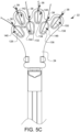
- FIGS. 5A-5H illustrate one embodiment of a usage example where sutures are loaded into a crimping instrument with an embodiment of a loading tool 22.
- a first suture end 128, a second suture end 130, a third suture end 132, a fourth suture end 134, a fifth suture end 136, and a sixth suture end 138 are each placed through respective suture openings 140, 142, 144, 146, 148, and 150.
- the target cover 24 is then removed, as depicted by the exposed target tray 26 and the exposed proximal snare loops 152 and the exposed distal snare loops 154 as shown in FIG. 5D .
- the suture clearance slots 38 can pass over the sutures 128, 130, 132, 134, 136, and 138.
- the handle 86 is moved in a proximal direction 156, which pulls the proximal snare loops 152 and the distal snare loops 154 towards the suture fastener (not visible in this view) held in the distal end of the device.
- the snare loops 152, 154 are pulled through the fasteners by the movement of the handle 86, so too are the snared sutures 128, 130, 132, 134, 136, and 138 also pulled through the fasteners.
- Embodiments like this where the proximal and distal snare loops are staggered, allow the different sutures to be pulled through the suture fastener at different times, thereby enabling the size of the crimpable fastener to be smaller.
- FIG. 5F shows the handle 86 having been moved more proximally, whereby the proximal snare loops have already been pulled through the suture fasteners, and the distal snare loops 154 are going through the suture fasteners.
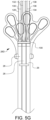
- FIG. 5G the sutures 128, 130, 132, 134, 136, 138 have been fully snared through not only the pledget 100 but also through the three suture fasteners. Although the suture fasteners are not visible in this view, there is one suture fastener in the distal end 28D of each shaft 28.
- the sutures 128 and 130 are passed through the first suture fastener.
- the sutures 132 and 134 are passed through the second suture fastener, and the sutures 136 and 138 are passed through the third suture fastener.
- the device has been flipped over to see the suture pairs 128, 130 and 132, 134 and 136, 138 exiting the slots 122 on the underside of the shafts 28.
- the sutures may be tensioned as desired, and the device lever may be squeezed, causing the pusher to move distally, thereby causing the wedge tip to compress the hammer towards the anvil, crimping the suture fastener therebetween so that it secures the sutures within the suture fastener.
- the cutting blade attached to the pusher can also cut the suture ends exiting the slots 122.
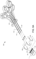
- FIGS. 6A-6C are partially exploded views illustrating another embodiment of a loading tool 158 for a surgical crimping instrument. This embodiment is similar to previous embodiments, except for the handle. In this embodiment, there are three separate handles 160 coupled to respective twisted snare wires 114, 116, and 118. These separate handles 160 are more easily loaded by an end user, one in each receiving face 50, for situations where the instrument is desired to be reloaded or user loaded. As illustrated in FIG. 6B , after the handles have been loaded into the instrument, the target cover 24 can be snapped onto the instrument, and the target tray 26 can be snapped over the instrument to cover the target cover 24. FIG. 6C shows the end result.
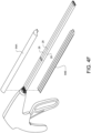
- FIG. 7 illustrates a further embodiment of a loading tool 162 for a surgical crimping instrument.
- the previous embodiments had three pairs of snare loops. This embodiment has one pair of snare loops. Other embodiments may have just one snare loop or an odd number of snare loops. Still other embodiments may have snare loops which are each substantially equidistant from the suture fasteners so that there is not a distinguishable difference between proximal vs distal snare loops.
Landscapes
- Health & Medical Sciences (AREA)
- Life Sciences & Earth Sciences (AREA)
- Surgery (AREA)
- Heart & Thoracic Surgery (AREA)
- Engineering & Computer Science (AREA)
- Biomedical Technology (AREA)
- Nuclear Medicine, Radiotherapy & Molecular Imaging (AREA)
- Medical Informatics (AREA)
- Molecular Biology (AREA)
- Animal Behavior & Ethology (AREA)
- General Health & Medical Sciences (AREA)
- Public Health (AREA)
- Veterinary Medicine (AREA)
- Surgical Instruments (AREA)
Claims (15)
- Ladewerkzeug (22) für ein Crimpinstrument (20), umfassend:eine Zielabdeckung (24), die eine oder mehrere Schlingenführungen (34) und eine oder mehrere Zielabdeckungs-Nahtöffnungen (36) definiert, von denen jede zumindest teilweise innerhalb einer entsprechenden der einen oder mehreren Schlingenführungen (34) liegt, und wobei die Zielabdeckung (24) ferner einen Nahtabstandsschlitz (38) definiert, der mit jeder der einen oder mehreren Zielabdeckungs-Nahtöffnungen (36) verbunden ist;eine Zielschale (26), das mit der Zielabdeckung (24) verbunden ist;ein oder mehrere Nahtverschlüsse (120);eine oder mehrere Schlingenschlaufen (98L), die jeweils um eine entsprechende der einen oder mehreren Schlingenführungen (34) gewickelt sind; undmindestens einen Griff (86; 160), der mit der einen oder den mehreren Schlingenschlaufen (98L) gekoppelt ist, so dass eine Bewegung des mindestens einen Griffs (86; 160) relativ zu dem einen oder den mehreren Nahtverschlüssen (120) die eine oder mehrere Schlingenschlaufen (98L), an die der mindestens eine Griff (86; 160) gekoppelt ist, durch einen oder mehrere der Nahtverschlüsse (120) zieht.
- Ladewerkzeug (22) nach Anspruch 1, wobei die eine oder mehreren Schlingenführungen (34) mindestens ein Paar Schlingenführungen umfassen.
- Ladewerkzeug (22) nach Anspruch 2, wobei jedes des mindestens einen Paares von Schlingenführungen (34) eine proximale Schlaufenführung (94) und eine distale Schlaufenführung (96) umfasst.
- Ladewerkzeug (22) nach Anspruch 3, wobei jede der einen oder mehreren Schlingenschlaufen (98L) mindestens ein Paar Schlingenschlaufen aufweist, das umfasst:eine proximale Schlingenschlaufe (152), die um die proximale Schlingenführung (94) des mindestens einen Paares von Schlingenführungen gebildet ist; undeine distale Schlingenschlaufe (154), die um die distale Schlingenführung (96) des mindestens einen Paares von Schlingenführungen gebildet ist.
- Ladewerkzeug (22) nach Anspruch 4, wobei jedes des mindestens einen Paares von Schlingenschlaufen mit dem mindestens einen Griff (86; 160) durch einen entsprechenden der einen oder mehreren Nahtverschlüsse (120) verbunden ist.
- Ladewerkzeug (22) nach Anspruch 5 umfasst ferner ein Pledget (100), durch das die eine oder mehrere Schlingenschlaufen (98L) auch mit dem mindestens einen Griff (86; 160) verbunden sind.
- Ladewerkzeug (22) nach Anspruch 1, wobei die Zielschale (26) eine oder mehrere Zielschalen-Nahtöffnungen (42) definiert, von denen jede einer der einen oder mehreren Zielabdeckungs-Nahtöffnungen (36) entspricht.
- Ladewerkzeug (22) nach Anspruch 1, wobei die Zielabdeckung (24) ferner eine Kupplungsverriegelung (40) umfasst.
- Ladewerkzeug (22) nach Anspruch 1, wobei die Zielschale (26) außerdem eine Kupplungsverriegelung (46) umfasst.
- Ladewerkzeug (22) nach Anspruch 1, wobei die eine oder die mehreren Nahtverschlüsse (120) einen Titanbefestiger umfassen.
- Ladewerkzeug (22) nach Anspruch 1, wobei der mindestens eine Griff einen verschiebbaren Griff (86) umfasst.
- Ladewerkzeug (22) nach Anspruch 1, wobei der mindestens eine Griff eine Vielzahl von gebogenen Griffen (160) umfasst.
- Instrument (20) zum Crimpen von einem oder mehreren Nahtverschlüssen an einen oder mehreren entsprechenden chirurgischen Nähten, wobei das Instrument umfasst:mindestens einen Schaft (28);eine oder mehrere Aufnahmeflächen (50), die jeweils zur Aufnahme eines oder mehrerer Nahtverschlüsse (120) ausgebildet sind;einen oder mehrere Ambosse (54), wobei jeder der einen oder mehreren Ambosse (54) einer der ein oder mehreren Aufnahmeflächen (50) entspricht;einen oder mehrere Hämmer (52), wobei jeder der einen oder der mehreren Hämmer (52) einem der einen oder mehreren Ambosse (54) entspricht und relativ zu seinem korrespondierenden Amboss (54) beweglich ist, um den einen oder die mehreren Nahtverschlüsse (120) dazwischen zu quetschen und in der einen oder den mehreren Aufnahmeflächen (50) aufzunehmen; undeinen oder mehrere Drücker (56), die in einer Richtung im Wesentlichen parallel zu einer Längsachse des mindestens einen Schafts (28) beweglich und so ausgebildet sind, dass sie mit mindestens einem von Hammer (52) und Amboss (54) in Eingriff kommen, um den Hammer (52) und den Amboss (54) zusammenzudrücken;gekennzeichnet durch ein Ladewerkzeug (22) nach einem der Ansprüche 1 bis 12.
- Instrument (20) nach Anspruch 13, wobei jede der eine oder mehreren Nahtverschlüssen innerhalb einer entsprechenden der ein oder mehreren Aufnahmeflächen (50) des Instruments (20) angeordnet ist.
- Instrument nach Anspruch 13 oder 14, wobei der mindestens eine Griff (86) auf dem mindestens einen Schaft (28) verschiebbar ist.
Applications Claiming Priority (2)
| Application Number | Priority Date | Filing Date | Title |
|---|---|---|---|
| US201962838250P | 2019-04-24 | 2019-04-24 | |
| PCT/US2020/029686 WO2020219790A1 (en) | 2019-04-24 | 2020-04-24 | Crimping instrument and loading tool therefor |
Publications (3)
| Publication Number | Publication Date |
|---|---|
| EP3946077A1 EP3946077A1 (de) | 2022-02-09 |
| EP3946077A4 EP3946077A4 (de) | 2022-12-14 |
| EP3946077B1 true EP3946077B1 (de) | 2024-07-10 |
Family
ID=72941828
Family Applications (1)
| Application Number | Title | Priority Date | Filing Date |
|---|---|---|---|
| EP20795670.7A Active EP3946077B1 (de) | 2019-04-24 | 2020-04-24 | Crimp-instrument und ladewerkzeug dafür |
Country Status (7)
| Country | Link |
|---|---|
| US (1) | US12016551B2 (de) |
| EP (1) | EP3946077B1 (de) |
| JP (1) | JP7482151B2 (de) |
| CN (1) | CN113924049B (de) |
| AU (1) | AU2020263478B2 (de) |
| CA (1) | CA3134366A1 (de) |
| WO (1) | WO2020219790A1 (de) |
Family Cites Families (18)
| Publication number | Priority date | Publication date | Assignee | Title |
|---|---|---|---|---|
| CA2141911C (en) * | 1994-02-24 | 2002-04-23 | Jude S. Sauer | Surgical crimping device and method of use |
| US5693059A (en) * | 1995-09-15 | 1997-12-02 | Yoon; Inbae | Ligating instrument with multiple loop ligature supply and methods therefor |
| JPH10277044A (ja) * | 1997-04-03 | 1998-10-20 | Yuichi Matsuzawa | 手術用縫合糸の結紮方法 |
| US6171317B1 (en) * | 1999-09-14 | 2001-01-09 | Perclose, Inc. | Knot tying device and method |
| US7235086B2 (en) * | 2001-02-02 | 2007-06-26 | Lsi Solutions, Inc. | Crimping instrument with motion limiting feature |
| US20030078601A1 (en) * | 2001-10-22 | 2003-04-24 | Oleg Shikhman | Crimping and cutting device |
| US8932208B2 (en) | 2005-05-26 | 2015-01-13 | Maquet Cardiovascular Llc | Apparatus and methods for performing minimally-invasive surgical procedures |
| US20110046642A1 (en) * | 2009-08-21 | 2011-02-24 | Coloplast A/S | Suture assembly and system |
| US9943303B2 (en) * | 2011-05-04 | 2018-04-17 | Lsi Solutions, Inc. | Method of passing suture tails through a surgical pledget |
| EP2825101A4 (de) | 2012-03-13 | 2015-12-16 | Suture Ease Llc | Nadel- und schlingenführung zum durchführen einer naht |
| US8894684B2 (en) * | 2012-05-07 | 2014-11-25 | Medos International Sàrl | Systems, devices, and methods for securing tissue using a suture having one or more protrusions |
| US10016193B2 (en) * | 2013-11-18 | 2018-07-10 | Edwards Lifesciences Ag | Multiple-firing crimp device and methods for using and manufacturing same |
| WO2015006739A1 (en) * | 2013-07-11 | 2015-01-15 | Edwards Lifesciences Corporation | Knotless suture fastener installation system |
| US10603027B2 (en) | 2014-07-08 | 2020-03-31 | Lsi Solutions, Inc. | Crimping instrument with reduced dimension, continued compatibility, and tissue protection features |
| CR20170265A (es) | 2014-12-10 | 2017-11-17 | Edwards Lifesciences Ag | Dispositivo de sujeción de reactivación múltiple y métodos para su utilización y fabricación |
| CN107106162B (zh) * | 2014-12-24 | 2020-10-27 | 爱德华兹生命科学公司 | 缝合夹部署装置 |
| US10863980B2 (en) * | 2016-12-28 | 2020-12-15 | Edwards Lifesciences Corporation | Suture fastener having spaced-apart layers |
| US20180271516A1 (en) * | 2017-03-22 | 2018-09-27 | Lsi Solutions, Inc. | System and method for stay suture management |
-
2020
- 2020-04-24 EP EP20795670.7A patent/EP3946077B1/de active Active
- 2020-04-24 AU AU2020263478A patent/AU2020263478B2/en active Active
- 2020-04-24 CA CA3134366A patent/CA3134366A1/en active Pending
- 2020-04-24 US US17/604,574 patent/US12016551B2/en active Active
- 2020-04-24 CN CN202080038836.4A patent/CN113924049B/zh active Active
- 2020-04-24 WO PCT/US2020/029686 patent/WO2020219790A1/en not_active Ceased
- 2020-04-24 JP JP2021562112A patent/JP7482151B2/ja active Active
Also Published As
| Publication number | Publication date |
|---|---|
| CN113924049B (zh) | 2025-09-02 |
| BR112021021272A2 (pt) | 2021-12-21 |
| WO2020219790A1 (en) | 2020-10-29 |
| CA3134366A1 (en) | 2020-10-29 |
| JP2022529487A (ja) | 2022-06-22 |
| JP7482151B2 (ja) | 2024-05-13 |
| AU2020263478B2 (en) | 2023-05-25 |
| CN113924049A (zh) | 2022-01-11 |
| EP3946077A1 (de) | 2022-02-09 |
| US12016551B2 (en) | 2024-06-25 |
| EP3946077A4 (de) | 2022-12-14 |
| US20220192658A1 (en) | 2022-06-23 |
| AU2020263478A1 (en) | 2021-11-11 |
Similar Documents
| Publication | Publication Date | Title |
|---|---|---|
| CA2959990C (en) | Crimping instrument with reduced dimension, continued compatibility, and tissue protection features | |
| CA2149833C (en) | Surgical incision members for endoscopic suturing apparatus | |
| US12349895B2 (en) | Knotless anchor insertion | |
| EP1712198A2 (de) | Knochenfixationsvorrichtung für chirurgische Eingriffe, Schneidegerät und Bandverbindungsstück | |
| CN101674777B (zh) | 缝合、卷曲和切割装置 | |
| US11937805B2 (en) | Rotation adapter and receiver for minimally invasive surgical devices | |
| CN110225716B (zh) | 具有间隔开的层的缝合线紧固件 | |
| EP3337378B1 (de) | Drehadapter und empfänger für minimal invasive chirurgische vorrichtungen | |
| CN106132318A (zh) | 手术用器具 | |
| EP3413804B1 (de) | Sohlenplattenreparatur | |
| EP2967543B1 (de) | Medizinische vorrichtung zur abgabe eines implantats | |
| AU2020263478B2 (en) | Crimping instrument and loading tool therefor | |
| BR112021021272B1 (pt) | Ferramenta de carregamento para um instrumento de frisagem e instrumento de frisagem | |
| US20240206868A1 (en) | Rotation adapter and receiver for minimally invasive surgical devices | |
| US12629146B2 (en) | Rotation adapter and receiver for minimally invasive surgical devices |
Legal Events
| Date | Code | Title | Description |
|---|---|---|---|
| STAA | Information on the status of an ep patent application or granted ep patent |
Free format text: STATUS: THE INTERNATIONAL PUBLICATION HAS BEEN MADE |
|
| PUAI | Public reference made under article 153(3) epc to a published international application that has entered the european phase |
Free format text: ORIGINAL CODE: 0009012 |
|
| STAA | Information on the status of an ep patent application or granted ep patent |
Free format text: STATUS: REQUEST FOR EXAMINATION WAS MADE |
|
| 17P | Request for examination filed |
Effective date: 20211029 |
|
| AK | Designated contracting states |
Kind code of ref document: A1 Designated state(s): AL AT BE BG CH CY CZ DE DK EE ES FI FR GB GR HR HU IE IS IT LI LT LU LV MC MK MT NL NO PL PT RO RS SE SI SK SM TR |
|
| DAV | Request for validation of the european patent (deleted) | ||
| DAX | Request for extension of the european patent (deleted) | ||
| A4 | Supplementary search report drawn up and despatched |
Effective date: 20221111 |
|
| RIC1 | Information provided on ipc code assigned before grant |
Ipc: A61B 90/00 20160101ALI20221107BHEP Ipc: A61B 17/00 20060101ALI20221107BHEP Ipc: A61B 17/04 20060101AFI20221107BHEP |
|
| GRAP | Despatch of communication of intention to grant a patent |
Free format text: ORIGINAL CODE: EPIDOSNIGR1 |
|
| STAA | Information on the status of an ep patent application or granted ep patent |
Free format text: STATUS: GRANT OF PATENT IS INTENDED |
|
| INTG | Intention to grant announced |
Effective date: 20240131 |
|
| GRAS | Grant fee paid |
Free format text: ORIGINAL CODE: EPIDOSNIGR3 |
|
| GRAA | (expected) grant |
Free format text: ORIGINAL CODE: 0009210 |
|
| STAA | Information on the status of an ep patent application or granted ep patent |
Free format text: STATUS: THE PATENT HAS BEEN GRANTED |
|
| AK | Designated contracting states |
Kind code of ref document: B1 Designated state(s): AL AT BE BG CH CY CZ DE DK EE ES FI FR GB GR HR HU IE IS IT LI LT LU LV MC MK MT NL NO PL PT RO RS SE SI SK SM TR |
|
| REG | Reference to a national code |
Ref country code: CH Ref legal event code: EP |
|
| REG | Reference to a national code |
Ref country code: DE Ref legal event code: R096 Ref document number: 602020033827 Country of ref document: DE |
|
| REG | Reference to a national code |
Ref country code: LT Ref legal event code: MG9D |
|
| REG | Reference to a national code |
Ref country code: NL Ref legal event code: MP Effective date: 20240710 |
|
| PG25 | Lapsed in a contracting state [announced via postgrant information from national office to epo] |
Ref country code: PT Free format text: LAPSE BECAUSE OF FAILURE TO SUBMIT A TRANSLATION OF THE DESCRIPTION OR TO PAY THE FEE WITHIN THE PRESCRIBED TIME-LIMIT Effective date: 20241111 |
|
| REG | Reference to a national code |
Ref country code: AT Ref legal event code: MK05 Ref document number: 1701308 Country of ref document: AT Kind code of ref document: T Effective date: 20240710 |
|
| PG25 | Lapsed in a contracting state [announced via postgrant information from national office to epo] |
Ref country code: NL Free format text: LAPSE BECAUSE OF FAILURE TO SUBMIT A TRANSLATION OF THE DESCRIPTION OR TO PAY THE FEE WITHIN THE PRESCRIBED TIME-LIMIT Effective date: 20240710 |
|
| PG25 | Lapsed in a contracting state [announced via postgrant information from national office to epo] |
Ref country code: PT Free format text: LAPSE BECAUSE OF FAILURE TO SUBMIT A TRANSLATION OF THE DESCRIPTION OR TO PAY THE FEE WITHIN THE PRESCRIBED TIME-LIMIT Effective date: 20241111 Ref country code: NL Free format text: LAPSE BECAUSE OF FAILURE TO SUBMIT A TRANSLATION OF THE DESCRIPTION OR TO PAY THE FEE WITHIN THE PRESCRIBED TIME-LIMIT Effective date: 20240710 |
|
| PG25 | Lapsed in a contracting state [announced via postgrant information from national office to epo] |
Ref country code: NO Free format text: LAPSE BECAUSE OF FAILURE TO SUBMIT A TRANSLATION OF THE DESCRIPTION OR TO PAY THE FEE WITHIN THE PRESCRIBED TIME-LIMIT Effective date: 20241010 |
|
| PG25 | Lapsed in a contracting state [announced via postgrant information from national office to epo] |
Ref country code: GR Free format text: LAPSE BECAUSE OF FAILURE TO SUBMIT A TRANSLATION OF THE DESCRIPTION OR TO PAY THE FEE WITHIN THE PRESCRIBED TIME-LIMIT Effective date: 20241011 Ref country code: FI Free format text: LAPSE BECAUSE OF FAILURE TO SUBMIT A TRANSLATION OF THE DESCRIPTION OR TO PAY THE FEE WITHIN THE PRESCRIBED TIME-LIMIT Effective date: 20240710 Ref country code: PL Free format text: LAPSE BECAUSE OF FAILURE TO SUBMIT A TRANSLATION OF THE DESCRIPTION OR TO PAY THE FEE WITHIN THE PRESCRIBED TIME-LIMIT Effective date: 20240710 |
|
| PG25 | Lapsed in a contracting state [announced via postgrant information from national office to epo] |
Ref country code: BG Free format text: LAPSE BECAUSE OF FAILURE TO SUBMIT A TRANSLATION OF THE DESCRIPTION OR TO PAY THE FEE WITHIN THE PRESCRIBED TIME-LIMIT Effective date: 20240710 |
|
| PG25 | Lapsed in a contracting state [announced via postgrant information from national office to epo] |
Ref country code: LV Free format text: LAPSE BECAUSE OF FAILURE TO SUBMIT A TRANSLATION OF THE DESCRIPTION OR TO PAY THE FEE WITHIN THE PRESCRIBED TIME-LIMIT Effective date: 20240710 |
|
| PG25 | Lapsed in a contracting state [announced via postgrant information from national office to epo] |
Ref country code: AT Free format text: LAPSE BECAUSE OF FAILURE TO SUBMIT A TRANSLATION OF THE DESCRIPTION OR TO PAY THE FEE WITHIN THE PRESCRIBED TIME-LIMIT Effective date: 20240710 Ref country code: IS Free format text: LAPSE BECAUSE OF FAILURE TO SUBMIT A TRANSLATION OF THE DESCRIPTION OR TO PAY THE FEE WITHIN THE PRESCRIBED TIME-LIMIT Effective date: 20241110 |
|
| PG25 | Lapsed in a contracting state [announced via postgrant information from national office to epo] |
Ref country code: HR Free format text: LAPSE BECAUSE OF FAILURE TO SUBMIT A TRANSLATION OF THE DESCRIPTION OR TO PAY THE FEE WITHIN THE PRESCRIBED TIME-LIMIT Effective date: 20240710 |
|
| PG25 | Lapsed in a contracting state [announced via postgrant information from national office to epo] |
Ref country code: ES Free format text: LAPSE BECAUSE OF FAILURE TO SUBMIT A TRANSLATION OF THE DESCRIPTION OR TO PAY THE FEE WITHIN THE PRESCRIBED TIME-LIMIT Effective date: 20240710 Ref country code: RS Free format text: LAPSE BECAUSE OF FAILURE TO SUBMIT A TRANSLATION OF THE DESCRIPTION OR TO PAY THE FEE WITHIN THE PRESCRIBED TIME-LIMIT Effective date: 20241010 |
|
| PG25 | Lapsed in a contracting state [announced via postgrant information from national office to epo] |
Ref country code: RS Free format text: LAPSE BECAUSE OF FAILURE TO SUBMIT A TRANSLATION OF THE DESCRIPTION OR TO PAY THE FEE WITHIN THE PRESCRIBED TIME-LIMIT Effective date: 20241010 Ref country code: PL Free format text: LAPSE BECAUSE OF FAILURE TO SUBMIT A TRANSLATION OF THE DESCRIPTION OR TO PAY THE FEE WITHIN THE PRESCRIBED TIME-LIMIT Effective date: 20240710 Ref country code: NO Free format text: LAPSE BECAUSE OF FAILURE TO SUBMIT A TRANSLATION OF THE DESCRIPTION OR TO PAY THE FEE WITHIN THE PRESCRIBED TIME-LIMIT Effective date: 20241010 Ref country code: LV Free format text: LAPSE BECAUSE OF FAILURE TO SUBMIT A TRANSLATION OF THE DESCRIPTION OR TO PAY THE FEE WITHIN THE PRESCRIBED TIME-LIMIT Effective date: 20240710 Ref country code: IS Free format text: LAPSE BECAUSE OF FAILURE TO SUBMIT A TRANSLATION OF THE DESCRIPTION OR TO PAY THE FEE WITHIN THE PRESCRIBED TIME-LIMIT Effective date: 20241110 Ref country code: HR Free format text: LAPSE BECAUSE OF FAILURE TO SUBMIT A TRANSLATION OF THE DESCRIPTION OR TO PAY THE FEE WITHIN THE PRESCRIBED TIME-LIMIT Effective date: 20240710 Ref country code: GR Free format text: LAPSE BECAUSE OF FAILURE TO SUBMIT A TRANSLATION OF THE DESCRIPTION OR TO PAY THE FEE WITHIN THE PRESCRIBED TIME-LIMIT Effective date: 20241011 Ref country code: FI Free format text: LAPSE BECAUSE OF FAILURE TO SUBMIT A TRANSLATION OF THE DESCRIPTION OR TO PAY THE FEE WITHIN THE PRESCRIBED TIME-LIMIT Effective date: 20240710 Ref country code: ES Free format text: LAPSE BECAUSE OF FAILURE TO SUBMIT A TRANSLATION OF THE DESCRIPTION OR TO PAY THE FEE WITHIN THE PRESCRIBED TIME-LIMIT Effective date: 20240710 Ref country code: BG Free format text: LAPSE BECAUSE OF FAILURE TO SUBMIT A TRANSLATION OF THE DESCRIPTION OR TO PAY THE FEE WITHIN THE PRESCRIBED TIME-LIMIT Effective date: 20240710 Ref country code: AT Free format text: LAPSE BECAUSE OF FAILURE TO SUBMIT A TRANSLATION OF THE DESCRIPTION OR TO PAY THE FEE WITHIN THE PRESCRIBED TIME-LIMIT Effective date: 20240710 |
|
| REG | Reference to a national code |
Ref country code: DE Ref legal event code: R097 Ref document number: 602020033827 Country of ref document: DE |
|
| PG25 | Lapsed in a contracting state [announced via postgrant information from national office to epo] |
Ref country code: RO Free format text: LAPSE BECAUSE OF FAILURE TO SUBMIT A TRANSLATION OF THE DESCRIPTION OR TO PAY THE FEE WITHIN THE PRESCRIBED TIME-LIMIT Effective date: 20240710 Ref country code: DK Free format text: LAPSE BECAUSE OF FAILURE TO SUBMIT A TRANSLATION OF THE DESCRIPTION OR TO PAY THE FEE WITHIN THE PRESCRIBED TIME-LIMIT Effective date: 20240710 Ref country code: SM Free format text: LAPSE BECAUSE OF FAILURE TO SUBMIT A TRANSLATION OF THE DESCRIPTION OR TO PAY THE FEE WITHIN THE PRESCRIBED TIME-LIMIT Effective date: 20240710 |
|
| PG25 | Lapsed in a contracting state [announced via postgrant information from national office to epo] |
Ref country code: EE Free format text: LAPSE BECAUSE OF FAILURE TO SUBMIT A TRANSLATION OF THE DESCRIPTION OR TO PAY THE FEE WITHIN THE PRESCRIBED TIME-LIMIT Effective date: 20240710 |
|
| PG25 | Lapsed in a contracting state [announced via postgrant information from national office to epo] |
Ref country code: CZ Free format text: LAPSE BECAUSE OF FAILURE TO SUBMIT A TRANSLATION OF THE DESCRIPTION OR TO PAY THE FEE WITHIN THE PRESCRIBED TIME-LIMIT Effective date: 20240710 |
|
| PG25 | Lapsed in a contracting state [announced via postgrant information from national office to epo] |
Ref country code: IT Free format text: LAPSE BECAUSE OF FAILURE TO SUBMIT A TRANSLATION OF THE DESCRIPTION OR TO PAY THE FEE WITHIN THE PRESCRIBED TIME-LIMIT Effective date: 20240710 Ref country code: SK Free format text: LAPSE BECAUSE OF FAILURE TO SUBMIT A TRANSLATION OF THE DESCRIPTION OR TO PAY THE FEE WITHIN THE PRESCRIBED TIME-LIMIT Effective date: 20240710 |
|
| PLBE | No opposition filed within time limit |
Free format text: ORIGINAL CODE: 0009261 |
|
| STAA | Information on the status of an ep patent application or granted ep patent |
Free format text: STATUS: NO OPPOSITION FILED WITHIN TIME LIMIT |
|
| 26N | No opposition filed |
Effective date: 20250411 |
|
| PGFP | Annual fee paid to national office [announced via postgrant information from national office to epo] |
Ref country code: DE Payment date: 20250509 Year of fee payment: 6 |
|
| PGFP | Annual fee paid to national office [announced via postgrant information from national office to epo] |
Ref country code: GB Payment date: 20250423 Year of fee payment: 6 |
|
| PGFP | Annual fee paid to national office [announced via postgrant information from national office to epo] |
Ref country code: FR Payment date: 20250422 Year of fee payment: 6 |
|
| PG25 | Lapsed in a contracting state [announced via postgrant information from national office to epo] |
Ref country code: SE Free format text: LAPSE BECAUSE OF FAILURE TO SUBMIT A TRANSLATION OF THE DESCRIPTION OR TO PAY THE FEE WITHIN THE PRESCRIBED TIME-LIMIT Effective date: 20240710 |
|
| REG | Reference to a national code |
Ref country code: CH Ref legal event code: H13 Free format text: ST27 STATUS EVENT CODE: U-0-0-H10-H13 (AS PROVIDED BY THE NATIONAL OFFICE) Effective date: 20251125 |
|
| PG25 | Lapsed in a contracting state [announced via postgrant information from national office to epo] |
Ref country code: LU Free format text: LAPSE BECAUSE OF NON-PAYMENT OF DUE FEES Effective date: 20250424 |
|
| PG25 | Lapsed in a contracting state [announced via postgrant information from national office to epo] |
Ref country code: MC Free format text: LAPSE BECAUSE OF FAILURE TO SUBMIT A TRANSLATION OF THE DESCRIPTION OR TO PAY THE FEE WITHIN THE PRESCRIBED TIME-LIMIT Effective date: 20240710 |
|
| REG | Reference to a national code |
Ref country code: BE Ref legal event code: MM Effective date: 20250430 |
|
| PG25 | Lapsed in a contracting state [announced via postgrant information from national office to epo] |
Ref country code: BE Free format text: LAPSE BECAUSE OF NON-PAYMENT OF DUE FEES Effective date: 20250430 |
|
| PG25 | Lapsed in a contracting state [announced via postgrant information from national office to epo] |
Ref country code: CH Free format text: LAPSE BECAUSE OF NON-PAYMENT OF DUE FEES Effective date: 20250430 |
|
| PG25 | Lapsed in a contracting state [announced via postgrant information from national office to epo] |
Ref country code: IE Free format text: LAPSE BECAUSE OF NON-PAYMENT OF DUE FEES Effective date: 20250424 |