EP3947925B1 - Dispositif de commande pour la soupape d'un moteur à combustion interne - Google Patents
Dispositif de commande pour la soupape d'un moteur à combustion interne Download PDFInfo
- Publication number
- EP3947925B1 EP3947925B1 EP20723199.4A EP20723199A EP3947925B1 EP 3947925 B1 EP3947925 B1 EP 3947925B1 EP 20723199 A EP20723199 A EP 20723199A EP 3947925 B1 EP3947925 B1 EP 3947925B1
- Authority
- EP
- European Patent Office
- Prior art keywords
- valve
- chamber
- driving
- piston
- rocker arm
- Prior art date
- Legal status (The legal status is an assumption and is not a legal conclusion. Google has not performed a legal analysis and makes no representation as to the accuracy of the status listed.)
- Active
Links
Images



Classifications
-
- F—MECHANICAL ENGINEERING; LIGHTING; HEATING; WEAPONS; BLASTING
- F01—MACHINES OR ENGINES IN GENERAL; ENGINE PLANTS IN GENERAL; STEAM ENGINES
- F01L—CYCLICALLY OPERATING VALVES FOR MACHINES OR ENGINES
- F01L1/00—Valve-gear or valve arrangements, e.g. lift-valve gear
- F01L1/12—Transmitting gear between valve drive and valve
- F01L1/18—Rocking arms or levers
- F01L1/181—Centre pivot rocking arms
-
- F—MECHANICAL ENGINEERING; LIGHTING; HEATING; WEAPONS; BLASTING
- F01—MACHINES OR ENGINES IN GENERAL; ENGINE PLANTS IN GENERAL; STEAM ENGINES
- F01L—CYCLICALLY OPERATING VALVES FOR MACHINES OR ENGINES
- F01L1/00—Valve-gear or valve arrangements, e.g. lift-valve gear
- F01L1/26—Valve-gear or valve arrangements, e.g. lift-valve gear characterised by the provision of two or more valves operated simultaneously by same transmitting-gear; peculiar to machines or engines with more than two lift-valves per cylinder
- F01L1/267—Valve-gear or valve arrangements, e.g. lift-valve gear characterised by the provision of two or more valves operated simultaneously by same transmitting-gear; peculiar to machines or engines with more than two lift-valves per cylinder with means for varying the timing or the lift of the valves
-
- F—MECHANICAL ENGINEERING; LIGHTING; HEATING; WEAPONS; BLASTING
- F01—MACHINES OR ENGINES IN GENERAL; ENGINE PLANTS IN GENERAL; STEAM ENGINES
- F01L—CYCLICALLY OPERATING VALVES FOR MACHINES OR ENGINES
- F01L13/00—Modifications of valve-gear to facilitate reversing, braking, starting, changing compression ratio, or other specific operations
- F01L13/06—Modifications of valve-gear to facilitate reversing, braking, starting, changing compression ratio, or other specific operations for braking
- F01L13/065—Compression release engine retarders of the "Jacobs Manufacturing" type
-
- F—MECHANICAL ENGINEERING; LIGHTING; HEATING; WEAPONS; BLASTING
- F01—MACHINES OR ENGINES IN GENERAL; ENGINE PLANTS IN GENERAL; STEAM ENGINES
- F01L—CYCLICALLY OPERATING VALVES FOR MACHINES OR ENGINES
- F01L1/00—Valve-gear or valve arrangements, e.g. lift-valve gear
- F01L1/02—Valve drive
- F01L1/04—Valve drive by means of cams, camshafts, cam discs, eccentrics or the like
- F01L1/047—Camshafts
- F01L2001/0475—Hollow camshafts
-
- F—MECHANICAL ENGINEERING; LIGHTING; HEATING; WEAPONS; BLASTING
- F01—MACHINES OR ENGINES IN GENERAL; ENGINE PLANTS IN GENERAL; STEAM ENGINES
- F01L—CYCLICALLY OPERATING VALVES FOR MACHINES OR ENGINES
- F01L13/00—Modifications of valve-gear to facilitate reversing, braking, starting, changing compression ratio, or other specific operations
- F01L2013/10—Auxiliary actuators for variable valve timing
- F01L2013/105—Hydraulic motors
-
- F—MECHANICAL ENGINEERING; LIGHTING; HEATING; WEAPONS; BLASTING
- F01—MACHINES OR ENGINES IN GENERAL; ENGINE PLANTS IN GENERAL; STEAM ENGINES
- F01L—CYCLICALLY OPERATING VALVES FOR MACHINES OR ENGINES
- F01L2305/00—Valve arrangements comprising rollers
Definitions
- US 2016/281612 A1 discloses a valve-actuating device for varying the valve lift.
- US 2019/0055861 A1 discloses a device for controlling at least one valve in an internal combustion engine.
- the object of the present invention is to obtain a control device for controlling the valve of an internal-combustion engine which reduces the drawbacks of the prior art.
- the rocker arm is hydraulically controlled to interrupt or not the kinematic chain that goes from the shaped shaft to the valve through the rocker arm.
- the control device can selectively enable the reading of protrusions through the actuation duct in a simple and reliable way and reduce malfunctions. In other words, the control device can control whether the passage of the rocker arm over the protrusion has an effect or not on the valve through a hydraulic control.
- the rocker arm comprises a first chamber, preferably a compensation chamber which houses part of a driving piston which in turn defines the position of the driving foot; a driving valve and a second chamber, preferably the second chamber is housed in the driving valve; the actuation duct is connected to the first chamber via the actuation valve; preferably the actuation valve is arranged between the first chamber and the actuation duct.
- the driving piston is movable within the first cavity between a first position and a second position as a function of the pressure of the actuation duct; and when the driving piston is in the first position, it pushes the foot towards the valve.
- the piston comprises an elongated element which extends from the third chamber to the second chamber passing through the opening, preferably the opening has a minimum diameter which is greater than the diameter of the elongated element so that a flow of liquid can flow between the opening and the elongated element from the second chamber to the third chamber and vice versa; preferably along the outer walls of the elongated element and the inner walls of the opening.
- control device comprises another rocker arm configured to be coupled to a valve assembly comprising the valve.
- Another object of the present invention is to obtain an engine-valvetrain assembly which reduces the drawbacks of the prior art.
- an engine-valvetrain assembly comprising at least one valve of an internal-combustion engine and a control device of a valve according to any one of the claims 1 to 12 is obtained; the engine-valvetrain assembly comprising a shaped shaft coupled to the rocker arm.
- the other valve is of the same type as the valve, consequently if the valve is an intake valve, the other valve is also an intake valve, if the valve is an exhaust valve, the other valve is also an exhaust valve.
- the engine-valvetrain assembly comprises a single exhaust or intake valve for each rocker arm and the rocker arm is directly connected to the exhaust or intake valve without interposition of the bridge.
- the driving piston 16 comprises a machined area which defines the housing seat 29 and which is located on the opposite side of the portion which abuts on the connecting element 4a.
- the machined area comprises a recess 50 obtained inside a central body 51 of the driving piston 16, a blocking element 52 which is defined by a partial annular frame 53 which extends from the central body 51 of driving piston 16 and defines the recess 50, which has a partially annular shape, between the partial annular frame 53 and the central body 51.
- the partial annular frame 53 comprises a partial annular side wall 54 and also a partial annular base wall 55.
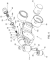
- valve 18 comprises a shutter guide 30; an elastic element 31 arranged between the shutter 25 and the shutter guide 30; an annular element 32 facing the shutter 25 from the side opposite the elastic element 31; a piston 33 having a main body 33a and an elongated element 33b; a protection element 34 of piston 33, in particular having a funnel shape; an elastic element 35 and a sleeve-shaped container element 36.
Landscapes
- Engineering & Computer Science (AREA)
- Mechanical Engineering (AREA)
- General Engineering & Computer Science (AREA)
- Valve Device For Special Equipments (AREA)
Claims (12)
- Dispositif de commande de la soupape d'un moteur à combustion interne ; le dispositif de commande (3) comprenant :- un culbuteur (7), qui est monté de manière à pouvoir tourner autour d'un premier axe (A1) et qui peut être couplé à un arbre de forme (5), en particulier un arbre à cames ;- un pied d'entraînement (15) configuré pour agir sur la soupape (2) ;- un dispositif d'actionnement (22, 23, 18, 16) logé dans le culbuteur (7) pour transmettre sélectivement un mouvement entre l'arbre de forme (5) et la soupape (2) ;- un conduit d'entraînement (17) en communication avec le dispositif d'actionnement (22, 23, 18, 16) ; le conduit d'entraînement (17) étant configuré pour activer ou désactiver hydrauliquement le dispositif d'actionnement (22, 23, 18, 16) ; de préférence, la soupape (2) est une soupape d'échappement ou d'admission ;le dispositif de commande étant caractérisé en ce que :le culbuteur (7) comprend un piston d'entraînement (16) et une première chambre (22), de préférence une chambre de compensation, qui loge une partie du piston d'entraînement (16), qui à son tour définit la position du pied d'entraînement (15) ; une soupape de commande (18) ; et une deuxième chambre (23), de préférence la deuxième chambre (23) est logée dans la soupape d'entraînement (18) ; le conduit d'entraînement (17) est relié à la première chambre (22) par la soupape d'entraînement (18) ; la soupape d'entraînement est disposée entre la première chambre (22) et le conduit d'entraînement (17) ;dans lequel la soupape d'entraînement (18) comprend une troisième chambre (42) en communication avec la deuxième chambre (23) par l'intermédiaire d'un élément de protection (34) interposé entre la deuxième et la troisième chambre (23, 42).
- Dispositif de commande selon la revendication 1, dans lequel le dispositif d'actionnement comprend un piston d'entraînement (16), qui définit la position du pied d'entraînement (15) ; en particulier, le piston d'entraînement (16) comprend le pied d'entraînement (15) ; le piston d'entraînement (16) est mobile à l'intérieur de la première chambre (22) de sorte que la distance entre le piston d'entraînement (16) et la soupape (2) peut varier ; en particulier, le piston d'entraînement (16) est coulissant par rapport au corps (11) du culbuteur (7) et le long d'un axe parallèle à un axe orthogonal au premier axe (A1).
- Dispositif de commande selon la revendication 1, dans lequel le piston d'entraînement (16) est mobile à l'intérieur de la première cavité (21) entre une première position et une deuxième position en fonction de la pression du conduit d'entraînement (17), et, lorsque le piston d'entraînement (16) est dans la première position, le pied (15) est poussé vers la soupape (2).
- Dispositif de commande selon l'une quelconque des revendications précédentes, la soupape d'entraînement (18) comprenant un obturateur (25) disposé entre la deuxième chambre (23) et la première chambre (22) et un piston (33) couplé à l'obturateur (25) pour pousser l'obturateur (25) dans une position ouverte.
- Dispositif de commande selon la revendication 1, dans lequel l'élément de protection (34) comprend une ouverture (34a) qui met la deuxième chambre (23) en communication avec la troisième chambre (42).
- Dispositif de commande selon la revendication 5, dans lequel le piston (33) comprend un élément allongé (33b), qui s'étend de la troisième chambre (42) à la deuxième chambre (23) en passant par l'ouverture (34a) de l'élément de protection (34), de préférence l'ouverture (34a) a un diamètre minimum qui est plus grand que le diamètre, de préférence maximal, de l'élément allongé (33b) afin qu'un flux de liquide puisse passer entre l'ouverture (34a) et l'élément allongé (33b) de la deuxième chambre (23) à la troisième chambre (42) et vice versa, de préférence le long des parois extérieures de l'élément allongé et des parois intérieures de l'ouverture (34a).
- Dispositif de commande selon la revendication 5 ou la revendication 6, dans lequel l'élément de protection (34) a une forme d'entonnoir avec une partie ayant un diamètre minimum et une partie ayant un diamètre maximum, et dans lequel la partie ayant le diamètre minimum fait face à la deuxième chambre (23) de préférence vers l'obturateur (25) .
- Dispositif de commande selon la revendication 4, dans lequel la soupape d'actionnement (18) comprend un premier élément élastique (35) couplé au piston (33) pour pousser le piston (32) le long d'une direction (D) avec un premier sens (V1) ; et un second élément élastique (31) couplé à l'obturateur (25) pour pousser l'obturateur (25) le long de la direction (D) avec un second sens (V2) opposé au premier sens (V1) ; dans lequel la force élastique du premier élément élastique (35) est plus grande que la force élastique du second élément élastique (31).
- Dispositif de commande selon l'une quelconque des revendications précédentes, comprenant un autre culbuteur (6) configuré pour être couplé à un ensemble de soupapes (2) comprenant la soupape (2) .
- Ensemble moteur-organes de distribution comprenant au moins une soupape (2) d'un moteur à combustion interne et un dispositif de commande (3) d'une soupape (2) selon l'une quelconque des revendications précédentes ; le moteur-organes de distribution (1) comprenant un arbre de forme (5), couplé au culbuteur (7) pour agir sur la soupape (2) par l'intermédiaire du culbuteur (7).
- Ensemble moteur-organes de distribution selon la revendication 10 comprenant au moins un ensemble de soupapes (2), comprenant la soupape (2) et une autre soupape (2) ; et dans lequel le culbuteur (7) est couplé à la soupape (2), de préférence de manière à agir exclusivement sur la soupape (2) ; et l'autre culbuteur (6) est couplé à l'ensemble de soupapes (2) par l'intermédiaire d'un pont (4) de manière à agir simultanément sur les deux soupapes (2).
- Ensemble moteur-organes de distribution selon la revendication 11, dans lequel l'arbre de forme (5) a une première came (9) ayant une pluralité de saillies (10) et une seconde came ayant un lobe principal, qui a une dimension radiale supérieure à chaque dimension radiale des saillies (10) ; et dans lequel la première came (9) est couplée au culbuteur (7) et la seconde came est couplée à l'autre culbuteur (6).
Applications Claiming Priority (2)
| Application Number | Priority Date | Filing Date | Title |
|---|---|---|---|
| IT102019000005022A IT201900005022A1 (it) | 2019-04-03 | 2019-04-03 | Un dispositivo di controllo per la valvola di un motore a combustione interna |
| PCT/IB2020/053201 WO2020202094A1 (fr) | 2019-04-03 | 2020-04-03 | Dispositif de commande pour la soupape d'un moteur à combustion interne |
Publications (2)
| Publication Number | Publication Date |
|---|---|
| EP3947925A1 EP3947925A1 (fr) | 2022-02-09 |
| EP3947925B1 true EP3947925B1 (fr) | 2024-07-03 |
Family
ID=67185625
Family Applications (1)
| Application Number | Title | Priority Date | Filing Date |
|---|---|---|---|
| EP20723199.4A Active EP3947925B1 (fr) | 2019-04-03 | 2020-04-03 | Dispositif de commande pour la soupape d'un moteur à combustion interne |
Country Status (3)
| Country | Link |
|---|---|
| EP (1) | EP3947925B1 (fr) |
| IT (1) | IT201900005022A1 (fr) |
| WO (1) | WO2020202094A1 (fr) |
Families Citing this family (2)
| Publication number | Priority date | Publication date | Assignee | Title |
|---|---|---|---|---|
| SE545489C2 (en) * | 2020-12-18 | 2023-09-26 | Gnutti Carlo Sweden Ab | Rocker arm valve mechanism |
| DE102024109291A1 (de) * | 2024-04-03 | 2025-10-09 | Schaeffler Technologies AG & Co. KG | Motorbremsvorrichtung für einen Ventiltrieb einer Brennkraftmaschine |
Family Cites Families (6)
| Publication number | Priority date | Publication date | Assignee | Title |
|---|---|---|---|---|
| DE102013215946A1 (de) * | 2013-08-12 | 2015-02-12 | Avl List Gmbh | Ventilbetätigungseinrichtung zur Veränderung des Ventilhubs |
| CN110145382B (zh) * | 2013-11-25 | 2021-08-13 | Pac制动公司 | 压缩释放制动系统 |
| KR20180008556A (ko) * | 2015-05-18 | 2018-01-24 | 이턴 에스알엘 | 어큐뮬레이터로서 작동하는 오일 배출 밸브를 갖는 로커 암 |
| EP3430246B1 (fr) * | 2016-03-14 | 2020-01-15 | Volvo Truck Corporation | Dispositif de commande d'au moins une soupape dans un moteur à combustion interne |
| DE112017002052T5 (de) * | 2016-05-10 | 2019-01-03 | Eaton Intelligent Power Limited | Modularer kipphebel |
| DE102017104196A1 (de) * | 2017-03-01 | 2018-09-06 | Schaeffler Technologies AG & Co. KG | Hydraulisches Abstützelement |
-
2019
- 2019-04-03 IT IT102019000005022A patent/IT201900005022A1/it unknown
-
2020
- 2020-04-03 WO PCT/IB2020/053201 patent/WO2020202094A1/fr not_active Ceased
- 2020-04-03 EP EP20723199.4A patent/EP3947925B1/fr active Active
Also Published As
| Publication number | Publication date |
|---|---|
| WO2020202094A1 (fr) | 2020-10-08 |
| IT201900005022A1 (it) | 2020-10-03 |
| EP3947925A1 (fr) | 2022-02-09 |
Similar Documents
| Publication | Publication Date | Title |
|---|---|---|
| US6192841B1 (en) | Device to limit valve seating velocities in limited lost motion tappets | |
| JP4637727B2 (ja) | 単一ポンピングピストンによって駆動され各エンジンシリンダに対して単一の電磁弁によって制御される可変駆動バルブを備えた内燃機関エンジン | |
| EP0939205B1 (fr) | Moteur à combustion interne avec commande hydraulique de soupape variable | |
| EP2162600B1 (fr) | Système d'actionnement de soupape variable | |
| EP1091097B1 (fr) | Ameliorations d'un dispositif de commande de soupape variable pour moteur à combustion interne | |
| US4829948A (en) | Valve operating device for internal combustion engine | |
| EP1740800B1 (fr) | Systeme d'actionnement de soupape a commande de siege de soupape | |
| US6474277B1 (en) | Method and apparatus for valve seating velocity control | |
| US5749340A (en) | Hydraulic tappets | |
| JPH09177526A (ja) | 内燃機関のブレーキシステム | |
| KR20010031816A (ko) | 로스트 모션 완전 인가방식의 밸브 작동시스템 | |
| EP2722499B1 (fr) | Appareil de contrôle de la synchronisation d'une soupape variable | |
| EP3947925B1 (fr) | Dispositif de commande pour la soupape d'un moteur à combustion interne | |
| US5327860A (en) | Hydraulic tappet-clearance compensating arrangement for a cam-controlled valve lifter | |
| EP1869294B1 (fr) | Systeme de commande de soupape a controle du siege de soupape | |
| GB2053350A (en) | Ic engine valve gear | |
| EP1243763B1 (fr) | Moteur à commande hydraulique variable de soupape et dispositif de purge du circuit hydraulique | |
| JP4639130B2 (ja) | 可変動作を行うバルブ及びロッカーアームによってバルブを制御する油圧作動ユニットを有する内燃エンジン | |
| EP0990773A2 (fr) | Dispositif hydraulique de rattrapage de jeu avec soupape de decharge | |
| JP2026506391A (ja) | 外向きに弾発する液圧アクチュエータピストンを有するロッカーアーム | |
| CN117980589A (zh) | 两级气门闭合摇臂组合件 | |
| HK1115178B (en) | Valve actuation system with valve seating control | |
| JPH041407A (ja) | 多気筒エンジンの弁作動装置 |
Legal Events
| Date | Code | Title | Description |
|---|---|---|---|
| STAA | Information on the status of an ep patent application or granted ep patent |
Free format text: STATUS: UNKNOWN |
|
| STAA | Information on the status of an ep patent application or granted ep patent |
Free format text: STATUS: THE INTERNATIONAL PUBLICATION HAS BEEN MADE |
|
| PUAI | Public reference made under article 153(3) epc to a published international application that has entered the european phase |
Free format text: ORIGINAL CODE: 0009012 |
|
| STAA | Information on the status of an ep patent application or granted ep patent |
Free format text: STATUS: REQUEST FOR EXAMINATION WAS MADE |
|
| 17P | Request for examination filed |
Effective date: 20211018 |
|
| AK | Designated contracting states |
Kind code of ref document: A1 Designated state(s): AL AT BE BG CH CY CZ DE DK EE ES FI FR GB GR HR HU IE IS IT LI LT LU LV MC MK MT NL NO PL PT RO RS SE SI SK SM TR |
|
| DAV | Request for validation of the european patent (deleted) | ||
| DAX | Request for extension of the european patent (deleted) | ||
| P01 | Opt-out of the competence of the unified patent court (upc) registered |
Effective date: 20230512 |
|
| GRAP | Despatch of communication of intention to grant a patent |
Free format text: ORIGINAL CODE: EPIDOSNIGR1 |
|
| STAA | Information on the status of an ep patent application or granted ep patent |
Free format text: STATUS: GRANT OF PATENT IS INTENDED |
|
| INTG | Intention to grant announced |
Effective date: 20240202 |
|
| GRAS | Grant fee paid |
Free format text: ORIGINAL CODE: EPIDOSNIGR3 |
|
| GRAA | (expected) grant |
Free format text: ORIGINAL CODE: 0009210 |
|
| STAA | Information on the status of an ep patent application or granted ep patent |
Free format text: STATUS: THE PATENT HAS BEEN GRANTED |
|
| AK | Designated contracting states |
Kind code of ref document: B1 Designated state(s): AL AT BE BG CH CY CZ DE DK EE ES FI FR GB GR HR HU IE IS IT LI LT LU LV MC MK MT NL NO PL PT RO RS SE SI SK SM TR |
|
| REG | Reference to a national code |
Ref country code: CH Ref legal event code: EP |
|
| REG | Reference to a national code |
Ref country code: DE Ref legal event code: R096 Ref document number: 602020033313 Country of ref document: DE |
|
| REG | Reference to a national code |
Ref country code: LT Ref legal event code: MG9D |
|
| REG | Reference to a national code |
Ref country code: NL Ref legal event code: MP Effective date: 20240703 |
|
| PG25 | Lapsed in a contracting state [announced via postgrant information from national office to epo] |
Ref country code: PT Free format text: LAPSE BECAUSE OF FAILURE TO SUBMIT A TRANSLATION OF THE DESCRIPTION OR TO PAY THE FEE WITHIN THE PRESCRIBED TIME-LIMIT Effective date: 20241104 |
|
| REG | Reference to a national code |
Ref country code: AT Ref legal event code: MK05 Ref document number: 1700017 Country of ref document: AT Kind code of ref document: T Effective date: 20240703 |
|
| PG25 | Lapsed in a contracting state [announced via postgrant information from national office to epo] |
Ref country code: NL Free format text: LAPSE BECAUSE OF FAILURE TO SUBMIT A TRANSLATION OF THE DESCRIPTION OR TO PAY THE FEE WITHIN THE PRESCRIBED TIME-LIMIT Effective date: 20240703 |
|
| PG25 | Lapsed in a contracting state [announced via postgrant information from national office to epo] |
Ref country code: PT Free format text: LAPSE BECAUSE OF FAILURE TO SUBMIT A TRANSLATION OF THE DESCRIPTION OR TO PAY THE FEE WITHIN THE PRESCRIBED TIME-LIMIT Effective date: 20241104 Ref country code: NL Free format text: LAPSE BECAUSE OF FAILURE TO SUBMIT A TRANSLATION OF THE DESCRIPTION OR TO PAY THE FEE WITHIN THE PRESCRIBED TIME-LIMIT Effective date: 20240703 |
|
| PG25 | Lapsed in a contracting state [announced via postgrant information from national office to epo] |
Ref country code: NO Free format text: LAPSE BECAUSE OF FAILURE TO SUBMIT A TRANSLATION OF THE DESCRIPTION OR TO PAY THE FEE WITHIN THE PRESCRIBED TIME-LIMIT Effective date: 20241003 |
|
| PG25 | Lapsed in a contracting state [announced via postgrant information from national office to epo] |
Ref country code: FI Free format text: LAPSE BECAUSE OF FAILURE TO SUBMIT A TRANSLATION OF THE DESCRIPTION OR TO PAY THE FEE WITHIN THE PRESCRIBED TIME-LIMIT Effective date: 20240703 Ref country code: GR Free format text: LAPSE BECAUSE OF FAILURE TO SUBMIT A TRANSLATION OF THE DESCRIPTION OR TO PAY THE FEE WITHIN THE PRESCRIBED TIME-LIMIT Effective date: 20241004 Ref country code: PL Free format text: LAPSE BECAUSE OF FAILURE TO SUBMIT A TRANSLATION OF THE DESCRIPTION OR TO PAY THE FEE WITHIN THE PRESCRIBED TIME-LIMIT Effective date: 20240703 |
|
| PG25 | Lapsed in a contracting state [announced via postgrant information from national office to epo] |
Ref country code: BG Free format text: LAPSE BECAUSE OF FAILURE TO SUBMIT A TRANSLATION OF THE DESCRIPTION OR TO PAY THE FEE WITHIN THE PRESCRIBED TIME-LIMIT Effective date: 20240703 |
|
| PG25 | Lapsed in a contracting state [announced via postgrant information from national office to epo] |
Ref country code: LV Free format text: LAPSE BECAUSE OF FAILURE TO SUBMIT A TRANSLATION OF THE DESCRIPTION OR TO PAY THE FEE WITHIN THE PRESCRIBED TIME-LIMIT Effective date: 20240703 |
|
| PG25 | Lapsed in a contracting state [announced via postgrant information from national office to epo] |
Ref country code: AT Free format text: LAPSE BECAUSE OF FAILURE TO SUBMIT A TRANSLATION OF THE DESCRIPTION OR TO PAY THE FEE WITHIN THE PRESCRIBED TIME-LIMIT Effective date: 20240703 Ref country code: IS Free format text: LAPSE BECAUSE OF FAILURE TO SUBMIT A TRANSLATION OF THE DESCRIPTION OR TO PAY THE FEE WITHIN THE PRESCRIBED TIME-LIMIT Effective date: 20241103 |
|
| PG25 | Lapsed in a contracting state [announced via postgrant information from national office to epo] |
Ref country code: HR Free format text: LAPSE BECAUSE OF FAILURE TO SUBMIT A TRANSLATION OF THE DESCRIPTION OR TO PAY THE FEE WITHIN THE PRESCRIBED TIME-LIMIT Effective date: 20240703 Ref country code: CZ Free format text: LAPSE BECAUSE OF FAILURE TO SUBMIT A TRANSLATION OF THE DESCRIPTION OR TO PAY THE FEE WITHIN THE PRESCRIBED TIME-LIMIT Effective date: 20240703 |
|
| PG25 | Lapsed in a contracting state [announced via postgrant information from national office to epo] |
Ref country code: RS Free format text: LAPSE BECAUSE OF FAILURE TO SUBMIT A TRANSLATION OF THE DESCRIPTION OR TO PAY THE FEE WITHIN THE PRESCRIBED TIME-LIMIT Effective date: 20241003 Ref country code: ES Free format text: LAPSE BECAUSE OF FAILURE TO SUBMIT A TRANSLATION OF THE DESCRIPTION OR TO PAY THE FEE WITHIN THE PRESCRIBED TIME-LIMIT Effective date: 20240703 |
|
| PG25 | Lapsed in a contracting state [announced via postgrant information from national office to epo] |
Ref country code: RS Free format text: LAPSE BECAUSE OF FAILURE TO SUBMIT A TRANSLATION OF THE DESCRIPTION OR TO PAY THE FEE WITHIN THE PRESCRIBED TIME-LIMIT Effective date: 20241003 Ref country code: PL Free format text: LAPSE BECAUSE OF FAILURE TO SUBMIT A TRANSLATION OF THE DESCRIPTION OR TO PAY THE FEE WITHIN THE PRESCRIBED TIME-LIMIT Effective date: 20240703 Ref country code: NO Free format text: LAPSE BECAUSE OF FAILURE TO SUBMIT A TRANSLATION OF THE DESCRIPTION OR TO PAY THE FEE WITHIN THE PRESCRIBED TIME-LIMIT Effective date: 20241003 Ref country code: LV Free format text: LAPSE BECAUSE OF FAILURE TO SUBMIT A TRANSLATION OF THE DESCRIPTION OR TO PAY THE FEE WITHIN THE PRESCRIBED TIME-LIMIT Effective date: 20240703 Ref country code: IS Free format text: LAPSE BECAUSE OF FAILURE TO SUBMIT A TRANSLATION OF THE DESCRIPTION OR TO PAY THE FEE WITHIN THE PRESCRIBED TIME-LIMIT Effective date: 20241103 Ref country code: HR Free format text: LAPSE BECAUSE OF FAILURE TO SUBMIT A TRANSLATION OF THE DESCRIPTION OR TO PAY THE FEE WITHIN THE PRESCRIBED TIME-LIMIT Effective date: 20240703 Ref country code: GR Free format text: LAPSE BECAUSE OF FAILURE TO SUBMIT A TRANSLATION OF THE DESCRIPTION OR TO PAY THE FEE WITHIN THE PRESCRIBED TIME-LIMIT Effective date: 20241004 Ref country code: FI Free format text: LAPSE BECAUSE OF FAILURE TO SUBMIT A TRANSLATION OF THE DESCRIPTION OR TO PAY THE FEE WITHIN THE PRESCRIBED TIME-LIMIT Effective date: 20240703 Ref country code: ES Free format text: LAPSE BECAUSE OF FAILURE TO SUBMIT A TRANSLATION OF THE DESCRIPTION OR TO PAY THE FEE WITHIN THE PRESCRIBED TIME-LIMIT Effective date: 20240703 Ref country code: CZ Free format text: LAPSE BECAUSE OF FAILURE TO SUBMIT A TRANSLATION OF THE DESCRIPTION OR TO PAY THE FEE WITHIN THE PRESCRIBED TIME-LIMIT Effective date: 20240703 Ref country code: BG Free format text: LAPSE BECAUSE OF FAILURE TO SUBMIT A TRANSLATION OF THE DESCRIPTION OR TO PAY THE FEE WITHIN THE PRESCRIBED TIME-LIMIT Effective date: 20240703 Ref country code: AT Free format text: LAPSE BECAUSE OF FAILURE TO SUBMIT A TRANSLATION OF THE DESCRIPTION OR TO PAY THE FEE WITHIN THE PRESCRIBED TIME-LIMIT Effective date: 20240703 |
|
| REG | Reference to a national code |
Ref country code: DE Ref legal event code: R097 Ref document number: 602020033313 Country of ref document: DE |
|
| PG25 | Lapsed in a contracting state [announced via postgrant information from national office to epo] |
Ref country code: RO Free format text: LAPSE BECAUSE OF FAILURE TO SUBMIT A TRANSLATION OF THE DESCRIPTION OR TO PAY THE FEE WITHIN THE PRESCRIBED TIME-LIMIT Effective date: 20240703 Ref country code: SM Free format text: LAPSE BECAUSE OF FAILURE TO SUBMIT A TRANSLATION OF THE DESCRIPTION OR TO PAY THE FEE WITHIN THE PRESCRIBED TIME-LIMIT Effective date: 20240703 Ref country code: DK Free format text: LAPSE BECAUSE OF FAILURE TO SUBMIT A TRANSLATION OF THE DESCRIPTION OR TO PAY THE FEE WITHIN THE PRESCRIBED TIME-LIMIT Effective date: 20240703 |
|
| PG25 | Lapsed in a contracting state [announced via postgrant information from national office to epo] |
Ref country code: EE Free format text: LAPSE BECAUSE OF FAILURE TO SUBMIT A TRANSLATION OF THE DESCRIPTION OR TO PAY THE FEE WITHIN THE PRESCRIBED TIME-LIMIT Effective date: 20240703 |
|
| PG25 | Lapsed in a contracting state [announced via postgrant information from national office to epo] |
Ref country code: SK Free format text: LAPSE BECAUSE OF FAILURE TO SUBMIT A TRANSLATION OF THE DESCRIPTION OR TO PAY THE FEE WITHIN THE PRESCRIBED TIME-LIMIT Effective date: 20240703 |
|
| PLBE | No opposition filed within time limit |
Free format text: ORIGINAL CODE: 0009261 |
|
| STAA | Information on the status of an ep patent application or granted ep patent |
Free format text: STATUS: NO OPPOSITION FILED WITHIN TIME LIMIT |
|
| 26N | No opposition filed |
Effective date: 20250404 |
|
| PGFP | Annual fee paid to national office [announced via postgrant information from national office to epo] |
Ref country code: DE Payment date: 20250428 Year of fee payment: 6 |
|
| PGFP | Annual fee paid to national office [announced via postgrant information from national office to epo] |
Ref country code: IT Payment date: 20250404 Year of fee payment: 6 |
|
| PG25 | Lapsed in a contracting state [announced via postgrant information from national office to epo] |
Ref country code: SE Free format text: LAPSE BECAUSE OF FAILURE TO SUBMIT A TRANSLATION OF THE DESCRIPTION OR TO PAY THE FEE WITHIN THE PRESCRIBED TIME-LIMIT Effective date: 20240703 |
|
| REG | Reference to a national code |
Ref country code: CH Ref legal event code: H13 Free format text: ST27 STATUS EVENT CODE: U-0-0-H10-H13 (AS PROVIDED BY THE NATIONAL OFFICE) Effective date: 20251125 |
|
| PG25 | Lapsed in a contracting state [announced via postgrant information from national office to epo] |
Ref country code: LU Free format text: LAPSE BECAUSE OF NON-PAYMENT OF DUE FEES Effective date: 20250403 |
|
| PG25 | Lapsed in a contracting state [announced via postgrant information from national office to epo] |
Ref country code: MC Free format text: LAPSE BECAUSE OF FAILURE TO SUBMIT A TRANSLATION OF THE DESCRIPTION OR TO PAY THE FEE WITHIN THE PRESCRIBED TIME-LIMIT Effective date: 20240703 |
|
| GBPC | Gb: european patent ceased through non-payment of renewal fee |
Effective date: 20250403 |
|
| REG | Reference to a national code |
Ref country code: BE Ref legal event code: MM Effective date: 20250430 |
|
| PG25 | Lapsed in a contracting state [announced via postgrant information from national office to epo] |
Ref country code: GB Free format text: LAPSE BECAUSE OF NON-PAYMENT OF DUE FEES Effective date: 20250403 |
|
| PG25 | Lapsed in a contracting state [announced via postgrant information from national office to epo] |
Ref country code: FR Free format text: LAPSE BECAUSE OF NON-PAYMENT OF DUE FEES Effective date: 20250430 |
|
| PG25 | Lapsed in a contracting state [announced via postgrant information from national office to epo] |
Ref country code: BE Free format text: LAPSE BECAUSE OF NON-PAYMENT OF DUE FEES Effective date: 20250430 |
|
| PG25 | Lapsed in a contracting state [announced via postgrant information from national office to epo] |
Ref country code: CH Free format text: LAPSE BECAUSE OF NON-PAYMENT OF DUE FEES Effective date: 20250430 |
|
| PG25 | Lapsed in a contracting state [announced via postgrant information from national office to epo] |
Ref country code: IE Free format text: LAPSE BECAUSE OF NON-PAYMENT OF DUE FEES Effective date: 20250403 |