EP3948254B1 - Procédés et appareil pour effectuer des mesures d'échantillons en utilisant la lumière visible sur des échantillons manipulés avec des ondes acoustiques - Google Patents
Procédés et appareil pour effectuer des mesures d'échantillons en utilisant la lumière visible sur des échantillons manipulés avec des ondes acoustiques Download PDFInfo
- Publication number
- EP3948254B1 EP3948254B1 EP20776699.9A EP20776699A EP3948254B1 EP 3948254 B1 EP3948254 B1 EP 3948254B1 EP 20776699 A EP20776699 A EP 20776699A EP 3948254 B1 EP3948254 B1 EP 3948254B1
- Authority
- EP
- European Patent Office
- Prior art keywords
- fluid
- flow cell
- card body
- glass flow
- sample
- Prior art date
- Legal status (The legal status is an assumption and is not a legal conclusion. Google has not performed a legal analysis and makes no representation as to the accuracy of the status listed.)
- Active
Links
Images



Classifications
-
- G—PHYSICS
- G01—MEASURING; TESTING
- G01N—INVESTIGATING OR ANALYSING MATERIALS BY DETERMINING THEIR CHEMICAL OR PHYSICAL PROPERTIES
- G01N29/00—Investigating or analysing materials by the use of ultrasonic, sonic or infrasonic waves; Visualisation of the interior of objects by transmitting ultrasonic or sonic waves through the object
- G01N29/02—Analysing fluids
-
- A—HUMAN NECESSITIES
- A61—MEDICAL OR VETERINARY SCIENCE; HYGIENE
- A61B—DIAGNOSIS; SURGERY; IDENTIFICATION
- A61B5/00—Measuring for diagnostic purposes; Identification of persons
- A61B5/145—Measuring characteristics of blood in vivo, e.g. gas concentration or pH-value ; Measuring characteristics of body fluids or tissues, e.g. interstitial fluid or cerebral tissue
- A61B5/14546—Measuring characteristics of blood in vivo, e.g. gas concentration or pH-value ; Measuring characteristics of body fluids or tissues, e.g. interstitial fluid or cerebral tissue for measuring analytes not otherwise provided for, e.g. ions, cytochromes
-
- A—HUMAN NECESSITIES
- A61—MEDICAL OR VETERINARY SCIENCE; HYGIENE
- A61B—DIAGNOSIS; SURGERY; IDENTIFICATION
- A61B5/00—Measuring for diagnostic purposes; Identification of persons
- A61B5/145—Measuring characteristics of blood in vivo, e.g. gas concentration or pH-value ; Measuring characteristics of body fluids or tissues, e.g. interstitial fluid or cerebral tissue
- A61B5/1455—Measuring characteristics of blood in vivo, e.g. gas concentration or pH-value ; Measuring characteristics of body fluids or tissues, e.g. interstitial fluid or cerebral tissue using optical sensors, e.g. spectral photometrical oximeters
-
- B—PERFORMING OPERATIONS; TRANSPORTING
- B01—PHYSICAL OR CHEMICAL PROCESSES OR APPARATUS IN GENERAL
- B01L—CHEMICAL OR PHYSICAL LABORATORY APPARATUS FOR GENERAL USE
- B01L3/00—Containers or dishes for laboratory use, e.g. laboratory glassware; Droppers
- B01L3/50—Containers for the purpose of retaining a material to be analysed, e.g. test tubes
- B01L3/502—Containers for the purpose of retaining a material to be analysed, e.g. test tubes with fluid transport, e.g. in multi-compartment structures
- B01L3/5027—Containers for the purpose of retaining a material to be analysed, e.g. test tubes with fluid transport, e.g. in multi-compartment structures by integrated microfluidic structures, i.e. dimensions of channels and chambers are such that surface tension forces are important, e.g. lab-on-a-chip
- B01L3/502715—Containers for the purpose of retaining a material to be analysed, e.g. test tubes with fluid transport, e.g. in multi-compartment structures by integrated microfluidic structures, i.e. dimensions of channels and chambers are such that surface tension forces are important, e.g. lab-on-a-chip characterised by interfacing components, e.g. fluidic, electrical, optical or mechanical interfaces
-
- B—PERFORMING OPERATIONS; TRANSPORTING
- B01—PHYSICAL OR CHEMICAL PROCESSES OR APPARATUS IN GENERAL
- B01L—CHEMICAL OR PHYSICAL LABORATORY APPARATUS FOR GENERAL USE
- B01L3/00—Containers or dishes for laboratory use, e.g. laboratory glassware; Droppers
- B01L3/52—Containers specially adapted for storing or dispensing a reagent
- B01L3/523—Containers specially adapted for storing or dispensing a reagent with means for closing or opening
-
- B—PERFORMING OPERATIONS; TRANSPORTING
- B01—PHYSICAL OR CHEMICAL PROCESSES OR APPARATUS IN GENERAL
- B01L—CHEMICAL OR PHYSICAL LABORATORY APPARATUS FOR GENERAL USE
- B01L2200/00—Solutions for specific problems relating to chemical or physical laboratory apparatus
- B01L2200/02—Adapting objects or devices to another
- B01L2200/025—Align devices or objects to ensure defined positions relative to each other
-
- B—PERFORMING OPERATIONS; TRANSPORTING
- B01—PHYSICAL OR CHEMICAL PROCESSES OR APPARATUS IN GENERAL
- B01L—CHEMICAL OR PHYSICAL LABORATORY APPARATUS FOR GENERAL USE
- B01L2200/00—Solutions for specific problems relating to chemical or physical laboratory apparatus
- B01L2200/02—Adapting objects or devices to another
- B01L2200/028—Modular arrangements
-
- B—PERFORMING OPERATIONS; TRANSPORTING
- B01—PHYSICAL OR CHEMICAL PROCESSES OR APPARATUS IN GENERAL
- B01L—CHEMICAL OR PHYSICAL LABORATORY APPARATUS FOR GENERAL USE
- B01L2200/00—Solutions for specific problems relating to chemical or physical laboratory apparatus
- B01L2200/06—Fluid handling related problems
- B01L2200/0689—Sealing
-
- B—PERFORMING OPERATIONS; TRANSPORTING
- B01—PHYSICAL OR CHEMICAL PROCESSES OR APPARATUS IN GENERAL
- B01L—CHEMICAL OR PHYSICAL LABORATORY APPARATUS FOR GENERAL USE
- B01L2200/00—Solutions for specific problems relating to chemical or physical laboratory apparatus
- B01L2200/16—Reagents, handling or storing thereof
-
- B—PERFORMING OPERATIONS; TRANSPORTING
- B01—PHYSICAL OR CHEMICAL PROCESSES OR APPARATUS IN GENERAL
- B01L—CHEMICAL OR PHYSICAL LABORATORY APPARATUS FOR GENERAL USE
- B01L2300/00—Additional constructional details
- B01L2300/02—Identification, exchange or storage of information
- B01L2300/025—Displaying results or values with integrated means
- B01L2300/027—Digital display, e.g. LCD, LED
-
- B—PERFORMING OPERATIONS; TRANSPORTING
- B01—PHYSICAL OR CHEMICAL PROCESSES OR APPARATUS IN GENERAL
- B01L—CHEMICAL OR PHYSICAL LABORATORY APPARATUS FOR GENERAL USE
- B01L2300/00—Additional constructional details
- B01L2300/08—Geometry, shape and general structure
- B01L2300/0809—Geometry, shape and general structure rectangular shaped
- B01L2300/0816—Cards, e.g. flat sample carriers usually with flow in two horizontal directions
-
- B—PERFORMING OPERATIONS; TRANSPORTING
- B01—PHYSICAL OR CHEMICAL PROCESSES OR APPARATUS IN GENERAL
- B01L—CHEMICAL OR PHYSICAL LABORATORY APPARATUS FOR GENERAL USE
- B01L2300/00—Additional constructional details
- B01L2300/08—Geometry, shape and general structure
- B01L2300/0861—Configuration of multiple channels and/or chambers in a single devices
- B01L2300/0874—Three dimensional network
-
- B—PERFORMING OPERATIONS; TRANSPORTING
- B01—PHYSICAL OR CHEMICAL PROCESSES OR APPARATUS IN GENERAL
- B01L—CHEMICAL OR PHYSICAL LABORATORY APPARATUS FOR GENERAL USE
- B01L2300/00—Additional constructional details
- B01L2300/08—Geometry, shape and general structure
- B01L2300/0861—Configuration of multiple channels and/or chambers in a single devices
- B01L2300/0877—Flow chambers
-
- B—PERFORMING OPERATIONS; TRANSPORTING
- B01—PHYSICAL OR CHEMICAL PROCESSES OR APPARATUS IN GENERAL
- B01L—CHEMICAL OR PHYSICAL LABORATORY APPARATUS FOR GENERAL USE
- B01L2300/00—Additional constructional details
- B01L2300/08—Geometry, shape and general structure
- B01L2300/0861—Configuration of multiple channels and/or chambers in a single devices
- B01L2300/0883—Serpentine channels
-
- B—PERFORMING OPERATIONS; TRANSPORTING
- B01—PHYSICAL OR CHEMICAL PROCESSES OR APPARATUS IN GENERAL
- B01L—CHEMICAL OR PHYSICAL LABORATORY APPARATUS FOR GENERAL USE
- B01L2300/00—Additional constructional details
- B01L2300/08—Geometry, shape and general structure
- B01L2300/0887—Laminated structure
-
- B—PERFORMING OPERATIONS; TRANSPORTING
- B01—PHYSICAL OR CHEMICAL PROCESSES OR APPARATUS IN GENERAL
- B01L—CHEMICAL OR PHYSICAL LABORATORY APPARATUS FOR GENERAL USE
- B01L2300/00—Additional constructional details
- B01L2300/16—Surface properties and coatings
- B01L2300/168—Specific optical properties, e.g. reflective coatings
-
- B—PERFORMING OPERATIONS; TRANSPORTING
- B01—PHYSICAL OR CHEMICAL PROCESSES OR APPARATUS IN GENERAL
- B01L—CHEMICAL OR PHYSICAL LABORATORY APPARATUS FOR GENERAL USE
- B01L2400/00—Moving or stopping fluids
- B01L2400/04—Moving fluids with specific forces or mechanical means
- B01L2400/0403—Moving fluids with specific forces or mechanical means specific forces
- B01L2400/0433—Moving fluids with specific forces or mechanical means specific forces vibrational forces
- B01L2400/0436—Moving fluids with specific forces or mechanical means specific forces vibrational forces acoustic forces, e.g. surface acoustic waves [SAW]
-
- B—PERFORMING OPERATIONS; TRANSPORTING
- B01—PHYSICAL OR CHEMICAL PROCESSES OR APPARATUS IN GENERAL
- B01L—CHEMICAL OR PHYSICAL LABORATORY APPARATUS FOR GENERAL USE
- B01L2400/00—Moving or stopping fluids
- B01L2400/04—Moving fluids with specific forces or mechanical means
- B01L2400/0403—Moving fluids with specific forces or mechanical means specific forces
- B01L2400/0433—Moving fluids with specific forces or mechanical means specific forces vibrational forces
- B01L2400/0439—Moving fluids with specific forces or mechanical means specific forces vibrational forces ultrasonic vibrations, vibrating piezo elements
-
- B—PERFORMING OPERATIONS; TRANSPORTING
- B01—PHYSICAL OR CHEMICAL PROCESSES OR APPARATUS IN GENERAL
- B01L—CHEMICAL OR PHYSICAL LABORATORY APPARATUS FOR GENERAL USE
- B01L2400/00—Moving or stopping fluids
- B01L2400/04—Moving fluids with specific forces or mechanical means
- B01L2400/0475—Moving fluids with specific forces or mechanical means specific mechanical means and fluid pressure
- B01L2400/0481—Moving fluids with specific forces or mechanical means specific mechanical means and fluid pressure squeezing of channels or chambers
-
- B—PERFORMING OPERATIONS; TRANSPORTING
- B01—PHYSICAL OR CHEMICAL PROCESSES OR APPARATUS IN GENERAL
- B01L—CHEMICAL OR PHYSICAL LABORATORY APPARATUS FOR GENERAL USE
- B01L2400/00—Moving or stopping fluids
- B01L2400/06—Valves, specific forms thereof
-
- B—PERFORMING OPERATIONS; TRANSPORTING
- B01—PHYSICAL OR CHEMICAL PROCESSES OR APPARATUS IN GENERAL
- B01L—CHEMICAL OR PHYSICAL LABORATORY APPARATUS FOR GENERAL USE
- B01L2400/00—Moving or stopping fluids
- B01L2400/06—Valves, specific forms thereof
- B01L2400/0605—Valves, specific forms thereof check valves
-
- B—PERFORMING OPERATIONS; TRANSPORTING
- B01—PHYSICAL OR CHEMICAL PROCESSES OR APPARATUS IN GENERAL
- B01L—CHEMICAL OR PHYSICAL LABORATORY APPARATUS FOR GENERAL USE
- B01L2400/00—Moving or stopping fluids
- B01L2400/06—Valves, specific forms thereof
- B01L2400/0633—Valves, specific forms thereof with moving parts
- B01L2400/0655—Valves, specific forms thereof with moving parts pinch valves
-
- B—PERFORMING OPERATIONS; TRANSPORTING
- B01—PHYSICAL OR CHEMICAL PROCESSES OR APPARATUS IN GENERAL
- B01L—CHEMICAL OR PHYSICAL LABORATORY APPARATUS FOR GENERAL USE
- B01L2400/00—Moving or stopping fluids
- B01L2400/08—Regulating or influencing the flow resistance
- B01L2400/082—Active control of flow resistance, e.g. flow controllers
-
- G—PHYSICS
- G01—MEASURING; TESTING
- G01N—INVESTIGATING OR ANALYSING MATERIALS BY DETERMINING THEIR CHEMICAL OR PHYSICAL PROPERTIES
- G01N21/00—Investigating or analysing materials by the use of optical means, i.e. using sub-millimetre waves, infrared, visible or ultraviolet light
- G01N21/17—Systems in which incident light is modified in accordance with the properties of the material investigated
- G01N21/25—Colour; Spectral properties, i.e. comparison of effect of material on the light at two or more different wavelengths or wavelength bands
- G01N21/31—Investigating relative effect of material at wavelengths characteristic of specific elements or molecules, e.g. atomic absorption spectrometry
- G01N21/314—Investigating relative effect of material at wavelengths characteristic of specific elements or molecules, e.g. atomic absorption spectrometry with comparison of measurements at specific and non-specific wavelengths
- G01N2021/3181—Investigating relative effect of material at wavelengths characteristic of specific elements or molecules, e.g. atomic absorption spectrometry with comparison of measurements at specific and non-specific wavelengths using LEDs
-
- G—PHYSICS
- G01—MEASURING; TESTING
- G01N—INVESTIGATING OR ANALYSING MATERIALS BY DETERMINING THEIR CHEMICAL OR PHYSICAL PROPERTIES
- G01N2201/00—Features of devices classified in G01N21/00
- G01N2201/06—Illumination; Optics
- G01N2201/062—LED's
- G01N2201/0627—Use of several LED's for spectral resolution
-
- G—PHYSICS
- G01—MEASURING; TESTING
- G01N—INVESTIGATING OR ANALYSING MATERIALS BY DETERMINING THEIR CHEMICAL OR PHYSICAL PROPERTIES
- G01N2291/00—Indexing codes associated with group G01N29/00
- G01N2291/02—Indexing codes associated with the analysed material
- G01N2291/021—Gases
-
- G—PHYSICS
- G01—MEASURING; TESTING
- G01N—INVESTIGATING OR ANALYSING MATERIALS BY DETERMINING THEIR CHEMICAL OR PHYSICAL PROPERTIES
- G01N2291/00—Indexing codes associated with group G01N29/00
- G01N2291/10—Number of transducers
- G01N2291/101—Number of transducers one transducer
Definitions
- the present application relates to diagnostic testing, and more particularly to methods for performing sample measurements using visible light on samples manipulated with acoustic waves.
- Acoustic waves may be employed to separate components of blood.
- red blood cells may be separated from other components of a blood sample using standing acoustic waves (e.g., acoustophoresis).
- standing acoustic waves e.g., acoustophoresis
- Such separation techniques may rely on differences in density and/or radius of the blood components, for example.
- US 9 512 421 B1 teaches an acoustic cell lysis system comprising a disposable cartridge that can be coupled to a platform having a small, high-frequency piezoelectric transducer array.
- the miniature acoustic lysis system can disrupt resilient cells, such as Mycobacterium tuberculosis (MTB).
- the transducer is configured to be coupled reversibly to the cartridge.
- the cartridge, the platform, and the lysis system can be formed from any useful material, such as poly(methyl methacrylate), polycarbonate, silicon, or glass.
- the system may include additional components, such as electrodes, amplifiers, pumps, valves, heating components, and detection components that can be used for colorimetric, fluorescent, chemiluminescent and other measurements.
- US 2004/0222091 A1 discloses a diagnostic card for use with a card reader in sensing at least one component concentration of a fluid sample.
- the diagnostic card comprises a card body, at least one component sensor in a sensor region of the card body, a sealed chamber in the card body outside the sensor region for containing a fluid, a fluid conduit connecting the chamber with the sensor region, a valve located in the chamber for connecting the chamber to the fluid conduit, and a delivery structure separate from the valve for forcing fluid from the chamber into the fluid conduit.
- the sensor region comprises a number of electrodes (130A, 130B) with sensor ends (132A, 132B).
- WO 2015/175188 A1 is directed to a microfluidic flow cell sub-assembly for encapsulating a sample to allow for subsequent controlled delivery of reagents to the sample, such as multiplexed in situ biomarker staining and analysis of a mounted biological sample using dye cycling.
- the microfluidic sub-assembly comprises an adherent layer, a transparent substrate layer, and a gasket layer. It may be assembled into a flow cell having fluidic connections outside of the main substrate.
- the flow cell further comprises a solid support adhered to the microfluidic flow cell assembly.
- the flow cell may be aligned with an objective lens of an imaging device, such as a microscope.
- a biological sample such as a blood sample or a tissue sample, may be encapsulated by the microfluidic sub-assembly such that it can be stained with a dye or imaged with a microscope.
- the fluidic inlet and outlet ports comprise thin film fluidic connectors which contain a microfluidic channel through which reagents can flow.
- the thin film connector may be bonded directly to the microfluidic flow cell. It may be enabled for heating/cooling, electromagnetic wave producing/transducing/sensing, or pressure/vacuum producing/transducing/sensing.
- a diagnostic card assembly includes a card body configured for insertion into an acoustic analyzer.
- the card body includes (1) a sample inlet port positioned to receive sample fluid; (2) a waste inlet port; (3) an outlet port; (4) a first fluid conduit extending between the sample inlet port and the outlet port; (5) a wash fluid chamber configured to hold a wash fluid; (6) a second fluid conduit extending between the wash fluid chamber and the outlet port; (7) a valve connecting the wash fluid chamber to the second fluid conduit and configured to control flow of wash fluid from the wash fluid chamber when the card body is inserted into the acoustic analyzer; (8) a waste fluid region configured to store waste sample fluid and waste wash fluid; and (9) a third fluid conduit extending between the waste input port and the waste fluid region.
- the card body is configured to be inserted into an acoustic analyzer and to sealingly couple to a glass flow cell within the acoustic analyzer, deliver sample fluid and wash fluid through the outlet port of the card body to a channel of the glass flow cell, and receive waste sample fluid and waste wash fluid from the glass flow cell.
- An acoustic analyzer includes (1) an opening configured to receive the disposable card body having a sample inlet port, a waste inlet port, an outlet port, a wash fluid chamber and a waste fluid region; (2) a mounting location positioned within the opening and configured to hold a replaceable, multi-use glass flow cell within the acoustic analyzer such that the glass flow cell sealingly couples to the disposable card body when the disposable card body is inserted into the acoustic analyzer; and (3) a transducer configured to generate standing waves in a channel of any glass flow cell positioned within the mounting location so as to spatially separate one or more components of a sample fluid within the channel.
- An acoustic analyzer system includes (1) an acoustic analyzer configured to receive a disposable card body and to perform one or more acoustic-wave assisted measurements on a fluid sample; and (2) a replaceable, multi-use glass flow cell positioned within the acoustic analyzer and configured to sealingly couple to the disposable card body when the disposable card body is inserted into the acoustic analyzer, the glass flow cell including an inlet, an outlet and a channel extending between the inlet and the outlet.
- the inlet of the glass flow cell is configured to receive sample fluid and wash fluid from an outlet port of the disposable card body, direct flow of sample fluid and wash fluid through the channel and to the outlet of the glass flow cell.
- the outlet of the glass flow cell is configured to provide sample fluid and wash fluid to a waste inlet port of the disposable card body.
- the acoustic analyzer includes a transducer, which is configured to produce a standing wave within the channel of the glass flow cell. The standing wave being capable of causing red blood cells within a blood sample within the channel to move away from other components within the blood sample. Further, the acoustic analyzer is configured to compress a wash fluid chamber of the disposable card body so as to move wash fluid into the channel of the glass flow cell, thereby washing the glass flow channel.
- a method of using an acoustic analyzer includes (1) receiving a card body within the acoustic analyzer, the card body including (a) a sample inlet port positioned to receive sample fluid; (b) a waste inlet port; (c) an outlet port; (d) a first fluid conduit extending between the sample inlet port and the outlet port; (e) a wash fluid chamber configured to hold a wash fluid; (f) a second fluid conduit extending between the wash fluid chamber and the outlet port; (g) a valve connecting the wash fluid chamber to the second fluid conduit and configured to control flow of wash fluid from the wash fluid chamber when the card body is inserted into the acoustic analyzer; (h) a waste fluid region configured to store waste sample fluid and waste wash fluid; and (i) a third fluid conduit extending between the waste inlet port and the waste fluid region; and (2) sealing the card body against a glass flow cell positioned with the acoustic analyzer, the glass flow cell including an inlet, an outlet and
- the inlet of the glass flow cell is configured to receive sample fluid and wash fluid from the outlet port of the card body, direct flow of sample fluid and wash fluid through the channel and to the outlet of the glass flow cell.
- the outlet of the glass flow cell is configured to provide sample fluid and wash fluid to the waste inlet port of the card body.
- the method further includes (3) receiving a sample fluid at the sample inlet port of the card body; (4) directing the sample fluid through the first fluid conduit, through the outlet port of the card body and through the inlet of the glass flow cell into the channel of the glass flow cell; producing a standing wave within the channel of the glass flow cell by a transducer included in the acoustic analyzer, the standing wave causing red blood cells within the sample fluid within the channel to move away from other components within the sample fluid such that components of the sample fluid become physically separated; (5) analyzing the sample fluid using the acoustic analyzer by performing one or more acoustic-wave assisted measurements on the sample fluid; and (6) directing the sample fluid from the channel of the glass flow cell through the outlet of the glass flow cell, through the waste inlet port of the card body, and through the third fluid conduit to the waste fluid region of the card body.
- an acoustic analyzer may be provided which includes a reusable glass flow cell that interfaces with a disposable card body.
- the disposable card body may be, for example, a single use card body.
- the disposable card body may be inserted into the acoustic analyzer and deliver sample fluid to the glass flow cell so that acoustic-wave assisted measurements may be performed on the sample fluid.
- the disposable card body may also deliver wash fluid to the glass flow cell, and receive waste sample fluid and waste wash fluid from the glass flow cell to prepare the glass flow cell for subsequent sample fluids.
- Such a system may allow for inexpensive and rapid testing of sample fluid, including a blood sample, using acoustophoresis as described further below.
- the disposable card body may include a sample fluid delivery conduit, a wash fluid region for storing wash fluid, and a waste fluid region.
- the disposable card body may be inserted into the acoustic analyzer, and the reusable glass flow cell may interface with the disposable card body within the analyzer. Thereafter, a syringe or similar delivery mechanism may provide sample fluid into the channel of the glass flow cell using the sample fluid delivery conduit of the disposable card body.
- the acoustic analyzer may then perform one or more acoustic-wave assisted measurements on the sample fluid.
- the wash fluid region of the disposable card body may deliver wash fluid to the channel of the glass flow cell to prepare the glass flow cell for another sample. Waste sample fluid and waste wash fluid may be stored on the disposable card body within the waste fluid region. The disposable card body may then be discarded, leaving the acoustic analyzer ready to receive a new disposable card body, and other sample fluid.
- the disposable card body may be formed from an inexpensive plastic material which includes the fluid delivery conduits, valve, wash fluid region, wash fluid, and waste fluid region used for delivery of a sample to the analyzer, cleaning of the glass flow cell and storage of any waste fluids. Unlike the glass of a glass flow cell, plastic may lack the stiffness and optical clarity needed for acoustophoresis.
- components of a sample fluid e.g., blood
- acoustic techniques such as acoustophoresis
- the glass flow cell may be re-used between 100 to 1000 times before replacement.
- an acoustic standing wave pattern may be generated within the channel of the glass flow cell using one or more acoustic transducers.
- the acoustic standing wave pattern may be employed to separate red blood cells from other components of a blood sample (e.g., plasma, leukocytes, platelets, etc.).
- One or more wavelengths of light e.g., red, orange, yellow, green, blue, indigo or violet
- FIGS. 1A-6 These and other embodiments of the present disclosure are described below with reference to FIGS. 1A-6 .
- Acoustic analyzer system 100 includes an acoustic analyzer 102 that has an opening 104 for receiving a disposable card body 106. Disposable card body 106 may be inserted in or removed from opening 104 of acoustic analyzer 102 as described further below. Acoustic analyzer 102 may include a display 108 having a user interface (not separately shown) that allows an operator to control operation of the acoustic analyzer 102, observe measurement results from testing performed by the acoustic analyzer 102, communicate measurement results to an external device such as a printer or a patient management system, etc. The portion of the acoustic analyzer 102 which houses the display 108 may be tiltable and/or detachable.
- acoustic analyzer 102 includes a glass flow cell 110 having a channel 112 in which a sample fluid is contained during testing with the acoustic analyzer 102.
- Disposable card body 106 includes a sample inlet port 114 coupled to a first fluid conduit 116, a wash fluid region 118 coupled to a second fluid conduit 120, and a waste fluid region 122 coupled to a third fluid conduit 124.
- first fluid conduit 116 couples sample inlet port 114 to glass flow cell 110
- second fluid conduit 120 couples wash fluid chamber 118 to glass flow cell 110
- third fluid conduit 124 couples waste fluid region 122 to glass flow cell 110.
- disposable card body 106 may be inserted into opening 104 of acoustic analyzer 102 so as to interface with glass flow cell 110.
- Sample inlet port 114 is positioned to receive sample fluid, such as a blood sample contained within a syringe, and to employ first fluid conduit 116 (also referred to as a sample fluid delivery conduit) of disposable card body 106 to deliver the sample fluid to channel 112 of glass flow cell 110.
- Acoustic analyzer 102 may then perform one or more measurements on the sample fluid (e.g., acoustophoresis-assisted hemolysis analysis) within channel 112 of glass flow cell 110.
- wash fluid may be provided to channel 112 from wash fluid region 118 through second fluid conduit 120.
- a bleach or other wash fluid solution may be delivered to channel 112 of glass flow cell 110 to remove sample fluid from channel 112 and prepare glass flow cell 110 for another sample.
- Waste sample fluid and waste wash fluid may travel through third fluid conduit 124 for storage in waste fluid region 122 of disposable card body 106.
- Disposable card body 106 may then be removed from acoustic analyzer 102 and discarded, leaving glass flow cell 110 ready to receive another sample delivered using a different disposable card body (not shown).
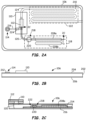
- FIGS. 2A and 2B illustrate a top plan view and a side plan view, respectively, of disposable card body 106 shown interfaced with glass flow cell 110.
- disposable card body 106 may include an inner region 202 having a top layer 204 and a bottom layer 206 formed thereon.
- Inner region 202 may be formed, for example, from a plastic material such as polycarbonate or a similar material.
- Top layer 204 and bottom layer 206 may be formed, for example, from a laminate material such as an adhesive coated polymer sheet or a similar material.
- Top layer 204 and/or bottom layer 206 may include labelling for card body 106, such as insertion directions for card body 106.
- Wash fluid region 118 may be formed within disposable card body 106 by one or more interconnected wash fluid chambers, for example.
- two wash fluid chambers 208a, 208b are shown. Fewer or more wash fluid chambers may be used. Wash fluid chambers 208a, 208b may be formed, for example, as trenches, grooves, or similar structures molded within inner region 202 of disposable card body 106.
- Waste fluid region 122 may be formed as a serpentine fluid conduit 210 having a length sufficient to hold waste sample fluid and waste wash fluid from channel 112 of glass flow cell 110.
- Serpentine fluid conduit 210 may be formed as a serpentine trench, groove, or similar structure molded within inner region 202 of disposable card body 106, for example.
- First fluid conduit 116, second fluid conduit 120 and third fluid conduit 124 also may be formed as trenches, grooves or similar structures molded within inner region 202 of disposable card body 106.
- Sample inlet port 114 may include a hole that extends through top layer 204 and inner region 202 to first fluid conduit 116.
- a sealing member 212, such as an adhesive element, may be included at sample inlet port 114 for engaging a syringe or other sample fluid containing device (not shown) that delivers sample fluid to sample inlet port 114.
- Other configurations for wash fluid region 118, waste fluid region 122, and/or conduits 116, 120 and 124 may be employed.
- FIG. 2C illustrates an example cross section view of disposable card body 106 taken along fluidic path 2C-2C in FIG. 2A .
- wash fluid chamber 208a may be formed between a top membrane 214 and a bottom membrane 216.
- top membrane 214 and/or bottom membrane 216 may be formed from a metal foil film or similar material.
- a one-way valve 224 such as a check valve, may be provided within first fluid conduit 116 so as to allow sample fluid to travel from sample inlet port 114 to glass flow cell 110, while preventing the flow of wash fluid from wash fluid chambers 208a, 208b toward sample inlet port 114 (e.g., when the glass flow cell 110 is being rinsed with wash fluid).
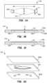
- FIG. 3A is a bottom plan view and FIG. 3B is a side plan view of glass flow cell 110 provided herein.
- glass flow cell 110 includes an inlet 302 coupled to a first side of channel 112 and an outlet 304 coupled to a second side of channel 112.
- channel 112 is shown as having an extended, diamond-shape with a length L, a width W (at its widest point), and a height H.
- Other channel shapes may be used, such as rectangular, cylindrical or the like.
- the channel width to height ratio W:H may be about 5:1 or greater, and the channel length L may be about 5 to 10 times the channel width W.
- Other relationships between channel length, width and/or height may be employed.
- Channel 112 may have a length L of about 1.25 mm to 20 mm, a width W of about 250 micrometers to 2 mm, and a height H of about 50 to 400 micrometers. Other lengths, heights, and/or widths may be used.
- Inlet 302 and/or outlet 304 may comprise a circular or otherwise shaped opening provided a path to channel 112.
- Inlet 302 and/or outlet 304 may have a diameter of about 100 micrometers to about 2 mm, although other diameters may be used. In general, the inlet 302 and/or outlet 304 may have a diameter that is similar to the width of the channel 112.
- Glass flow cell 110 may be formed from any suitable glass such as quartz glass, crown glass, flint glass, another type of optical glass or the like. A glass with a high acoustic impedance may be employed. Other glass types may be used.
- glass flow cell may be formed from a first glass piece 306 having the channel 112 formed therein and a second glass piece 308 having the inlet 302 and outlet 304 formed therein.
- First glass piece 306 and second glass piece 308 may be coupled together using any suitable mechanism including an adhesive, a mechanical coupling, a combination thereof, or the like.
- the first and second glass pieces 306 and 308 may be formed from the same material. Alternatively, different materials (e.g., different types of glass) may be used for the first and second glass pieces 306 and 308.
- FIG. 3C is a side plan view of glass flow cell 110 provided herein in which the edges of channel 112 are rounded. Other edge shapes may be used.
- FIG. 3D is an exploded, perspective view of glass flow cell 110 provided herein in which glass flow cell 110 is formed from three pieces of glass.
- first glass piece 306 having channel 112 formed therein
- second glass piece 308a having inlet 302 and outlet 304 formed therein
- third glass piece 308b e.g., without a channel, an inlet or an outlet
- Other layouts and/or numbers of glass pieces may be used.
- the same or different materials may be used for the first, second and third glass pieces 306, 308a and 308b.
- a combination of two or more of quartz glass, crown glass, flint glass, and any other optical glass may be used to form a glass flow cell.
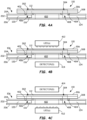
- First and second sealing members 402 and 404 may be part of card body 106 (e.g., provided within recesses (not shown) formed in card body 106), while in other embodiments, first and second sealing members 402 and 404 may be part of glass flow cell 110.
- Disposable card body 106 may include an outlet port 406 that aligns with inlet 302 of glass flow cell 110. Both first fluid conduit 116 (shown as a dashed box in FIG. 3A ) and second fluid conduit 120 may couple to outlet port 406. In this manner, sample fluid may be delivered to channel 112 by flowing from sample fluid inlet 114 ( FIG. 2A ) through first fluid conduit 116 and outlet port 406 of card body 106 into inlet 402 and channel 112 of glass flow cell 110. Likewise, wash fluid may flow from wash fluid region 118 ( FIG. 2A ) through second fluid conduit 120 and outlet port 406 of card body 106 into inlet 402 and channel 112 of glass flow cell 110.
- Disposable card body 106 may also include a waste inlet port 408 that aligns with outlet 304 of gas flow cell 110.
- Third fluid conduit 124 may couple to waste inlet port 408. In this manner, waste sample fluid and waste wash fluid may be delivered from channel 112 of glass flow cell 110 to waste fluid region 122 of card body 106 by flowing from channel 112 through outlet 304 of glass flow cell 110 into waste inlet port 408 of card body 106 and through third fluid conduit 124 into waste fluid region 122.
- sample fluid and wash fluid may be supplied from disposable card body 106 to channel 112 of glass flow cell 110, and waste sample fluid and wash fluid may be delivered back to disposable card body 106 so that glass flow cell 110 is available for another measurement on a different sample fluid. After receiving waste sample fluid and waste wash fluid, card body 106 may be discarded.
- Disposable card body 106 may include an opening 410 (or otherwise optically transparent region) that extends through a width of card body 106 and that aligns with channel 112 of glass flow cell 110. Opening 410 allows optical measurements to be performed on sample fluid contained within channel 112 of glass flow cell 110 as described further below.
- FIG. 4B illustrates one or more LEDs 412, such an LED string, positioned above channel 112 of glass flow cell 110.
- a single LED, multiple LEDs e.g., a linear LED string, a 2-dimentional array of LEDs and/or LED strings, etc.
- Other light sources may be used.
- a detector 414 may be positioned below opening 410 of card body 106 to receive optical signals transmitted from LED(s) 412 after the optical signals travel through channel 112. Information regarding the sample fluid in channel 112 may be obtained by observing what is absorbed by the sample fluid versus what is transmitted through the sample fluid.
- LED(s) 412 may be located below card body 106 and detector 414 may be located above channel 112 of glass flow cell 110 as shown in FIG. 4C .
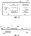
- FIG. 5A is a schematic top view of acoustic analyzer 102 of FIG. 1A illustrating various components that may be contained within acoustic analyzer 102.
- acoustic analyzer 102 may include glass flow cell 110, LED(s) 412 and detector 414 as previously described. Additionally, acoustic analyzer 102 may include one or more acoustic transducers, referred to as acoustic transducer 502 in FIG. 5A . More than one acoustic transducer 502 may be used.
- Acoustic analyzer 102 may also include a processor 504, a memory 506 and a user interface 508.
- Processor 504 may be coupled to and/or control operation of LED(s) 412, detector 414, acoustic transducer 502, memory 506 and/or user interface 508.
- Acoustic transducer 502 may be an ultrasonic or other frequency transducer configured to generate pressure waves in sample fluid within channel 112 of glass flow cell 110.
- acoustic transducer 502 may have a frequency selected based on dimensions of channel 112 so that a standing wave pattern is generated within channel 112.
- the standing wave pattern may cause components of sample fluid within channel 112 to become physically separated.
- the standing waves generated by acoustic transducer 502 may cause red blood cells within a blood sample within channel 112 to move away from other components within the blood sample.
- LED(s) 412 and detector 414 then may be used to probe the remaining blood components to detect concentration level and/or other characteristics of such blood components. Because red blood cells may scatter light, segregating the red blood cells from other blood components may facilitate measurements.
- acoustic transducer 502 may produce pressure waves at a frequency of between about 100 kilohertz to 1 megahertz. Other frequencies may be used.
- Processor 504 may be a computational resource such as a microprocessor, a microcontroller, an embedded microcontroller, a digital signal processor (DSP), a field programmable gate array (FPGA) configured to perform as a microcontroller, or the like.
- a microprocessor such as a microprocessor, a microcontroller, an embedded microcontroller, a digital signal processor (DSP), a field programmable gate array (FPGA) configured to perform as a microcontroller, or the like.
- DSP digital signal processor
- FPGA field programmable gate array
- Memory 506 may be any suitable type of memory, such as one or more of a volatile memory and/or a non-volatile memory.
- memory 506 may include a combination of different types of memory such as volatile memory and non-volatile memory.
- Volatile memory may include a static random access memory (SRAM), or a dynamic random access memory (DRAM).
- Non-volatile memory may include an electrically programmable read-only memory (EPROM), an electrically erasable programmable read-only memory (EEPROM), a flash memory, etc.
- Memory 506 may have a plurality of instructions stored therein that, when executed by processor 504, cause processor 504 to perform various actions specified by one or more of the stored plurality of instructions.
- User interface 508 may include one or more of a display screen (e.g., display 108), a touch panel and/or screen, an audio speaker, and a microphone, for example.
- User interface 508 may be controlled by processor 504, and functionality of user interface 508 may be implemented, at least in part, by computer-executable instructions (e.g., program code or software) stored in memory 506 and/or executed by processor 504 of acoustic analyzer 102.
- processor 504 may receive one or more measured results from detector 414, process the measured results to generate calculated results, and present the calculated results and/or other information, such as patient information, via user interface 508.
- user interface 508 may be configured to present one or more measured and/or calculated results to a user of acoustic analyzer 102.
- FIG. 5B is a side plan view illustrating an example layout of glass flow cell 110, one or more LED(s) 412, detector 414 and acoustic transducer 502 when card body 106 is inserted into acoustic analyzer 102. Other locations may be used for glass flow cell 110, LED(s) 412, detector 414 and/or acoustic transducer 502.
- FIG. 5C is a top plan view of an example embodiment of acoustic analyzer system 100 provided herein.
- disposable card body 106 is inserted into acoustic analyzer 102 so that it interfaces with glass flow cell 110.
- glass flow cell 110 may be positioned within acoustic analyzer 102 such that the inlet 302 and outlet 304 of glass flow cell 110 align with the outlet port 406 and waste inlet port 408, respectively, of disposable card body 106 after card body 106 is fully inserted into opening 104 ( FIG. 1B ) of acoustic sensor 102.
- a pressure sensitive switch (not shown) or other mechanism may detect the presence of card body 106 when it is fully inserted, and user interface 508 may indicate to a user whether card body 106 is properly positioned within acoustic analyzer 102 (and/or prevent analysis by acoustic analyzer 102 if card body 106 is not fully inserted).
- acoustic analyzer 102 may press card body 106 against glass flow cell 110, or glass flow cell 110 may be pressed against card body 106, so that sealing members 402 and 404 seal inlet 302 and outlet 304 of glass flow cell 110 relative to outlet port 406 and waste inlet port 408, respectively, of disposable card body 106.
- opening 104 of acoustic analyzer 102 may be sized so that card body 106 is pressed against glass flow cell 110 upon insertion within acoustic analyzer 102.
- a support member (not shown) within opening 104 may apply pressure against card body 106 upon insertion that biases card body 106 against glass flow cell 110.
- glass flow cell 110 may be lowered into contact with card body 106 after card body 106 is inserted into opening 104 of acoustic analyzer 102.
- Other mechanisms for sealing card body 106 relative to glass flow cell 110 may be employed.
- sample inlet port 114 of card body 106 is positioned to receive sample fluid, such as a blood sample contained within a syringe, and to employ first fluid conduit 116 of disposable card body 106 to deliver the sample fluid to channel 112 of glass flow cell 110.
- Acoustic analyzer 102 may then perform one or more measurements on the sample fluid (e.g., acoustophoresis-assisted hemolysis analysis or another measurement) within channel 112 of glass flow cell 110 using transducer 502 ( FIGS. 5A and 5B ) to position one or more sample components, and LED(s) 412 and detector 414 to perform measurements on one or more components of the sample fluid.
- one or more wavelengths of light may be used to probe the blood components to detect lipid level, bilirubin level, hemolysis level, free hemoglobin, or the like.
- Such information may be collected by processor 504 and/or displayed on user interface 508 (or otherwise communicated to a user of acoustic analyzer system 100).
- wash fluid may be provided to channel 112 from wash fluid chambers 208a and/or 208b through second fluid conduit 120.
- valve 218 may limit wash fluid flow within second fluid conduit 120 and glass flow cell 110.
- FIG. 5D illustrates an example cross section view of disposable card body 106 taken along fluidic path 5D-5D in FIG. 5C in accordance with one or more embodiments provided herein.
- movable plug 220 may block flow of wash fluid from wash fluid chamber 208a (and/or wash fluid chamber 208b) into second fluid conduit 120 and glass flow cell 110.
- movable plug 220 may be elevated by a pin element 510 within acoustic analyzer 102 so that top membrane 214 is torn or ruptured, such as at location 222 in FIG. 5D , releasing wash fluid from wash fluid chambers 208a, 208b into glass flow cell 110 through second fluid conduit 120 (as shown in the cross-section view of FIG. 5E ).
- acoustic analyzer 102 may employ an actuator element 512 that compresses wash fluid chamber 208a and/or wash fluid chamber 208b so as to push wash fluid into second fluid conduit 120, through channel 112 of glass flow cell 110 and into waste fluid region 122 (serpentine fluid conduit 210 in FIG.
- waste sample fluid and waste wash fluid travel through third fluid conduit 124 for storage in waste fluid region 122 of disposable card body 106.
- Disposable card body 106 may then be removed from acoustic analyzer 102 and discarded, leaving glass flow cell 110 ready to receive another sample delivered using a different disposable card body (not shown).
- glass flow cell 110 may be coupled to an upper support member 514 and pin element 510 and/or actuator element 512 may be coupled to a (moveable) lower support element 516 of acoustic analyzer 102.
- Other methods of supporting and/or moving glass flow cell 110, pin element 510 and/or actuator element 512 may be used.
- a mounting location 518 such as a notched region, is provided within upper support member 514 for supporting glass flow cell 110 (e.g., via an adhesive, screw, bolt or other securing mechanism). Other mounting locations and/or methods may be used.
- the wash fluid may be a bleach or other wash fluid solution.
- a 5% to 20% bleach solution may be used for the wash fluid stored on disposable card body 106.
- Other bleach solution concentrations and/or wash fluids may be used.
- FIG. 6 is a flowchart of an example method 600 of using acoustic analyzer system 100 in accordance with embodiments of the present disclosure.
- Method 600 begins with Block 602 at which a disposable card body is received within the acoustic analyzer.
- a disposable card body may be inserted into opening 104 in acoustic analyzer 102.
- display 108 and/or user interface 508 may prompt a user to enter user identification, scan a name tag or other barcode, enter a password or otherwise authenticate their identity.
- the card body is sealed against the glass flow cell positioned within the analyzer.
- sealing member 402 and 404 may seal glass flow cell 110 relative to card body 106.
- a sample fluid is received at the sample inlet port of the disposable card body.
- the sample fluid then may be directed through the outlet port of the disposable card body into the channel of the glass flow cell (in Block 608).
- a syringe or other sample fluid storage and/or delivery device may be employed to interface with sample inlet port 114 of card body 106. The syringe or other device may move sample fluid through sample inlet port 114, through first fluid conduit 116, through outlet 406 of card body 106, through inlet 302 of glass flow cell 110 and into channel 112.
- the acoustic analyzer may analyze the sample fluid.
- acoustic analyzer 102 may perform one or more measurements on the sample fluid within channel 112 of glass flow cell 110 using transducer 502 ( FIGS. 5A and 5B ) to position one or more sample fluid components, and LED(s) 412 and detector 414 to perform measurements on one or more sample fluid components.
- ultrasonic energy from transducer 502 may be used to separate red blood cells from plasma within channel 112 and/or one or more wavelengths of light from LED(s) 412 may be used to probe blood components to detect lipid level, bilirubin level, hemolysis level, free hemoglobin, or other blood component characteristics. Such information may be collected by processor 504 and/or displayed on user interface 508 (or otherwise communicated to a user of acoustic analyzer system 100).
- measurements may be performed on sample fluid while it is stationary within channel 112 of glass flow cell 110. In other embodiments, measurements may be performed while sample fluid travels through channel 112. Sample fluid amounts of less than 10 microliters may be employed in some embodiments, although other sample fluid amounts may be used.
- the sample fluid within the channel of the glass flow cell may be directed through the outlet of the glass flow cell to the waste fluid region of the disposable card body.
- wash fluid from wash fluid region 118 may be directed into second fluid conduit 120 of card body 106, through outlet port 406, through channel 112 of glass flow cell 110, through waste inlet port 408 of card body 106, and into waste fluid region 122 (serpentine fluid conduit 210 in FIG. 5A ).
- waste sample fluid and waste wash fluid travel through third fluid conduit 124 for storage in waste fluid region 122 of disposable card body 106.
- Disposable card body 106 may then be removed from acoustic analyzer 102 and discarded, leaving glass flow cell 110 ready to receive another sample delivered using a different disposable card body.
- components of a sample fluid may be manipulated within the glass flow cell using acoustic techniques, and the disposable card body may be used for sample fluid and wash fluid delivery, as well as for waste fluid disposal.
- the glass flow cell may be re-used within acoustic analyzer 102 between 100 to 1000 times before replacement.
- Disposable card body 106 and glass flow cell 110 may be part of and/or form a "diagnostic card assembly" that may be used in an acoustic analyzer for performing acoustic-wave assisted measurements, such as acoustophoresis-assisted hemolysis analysis.
Landscapes
- Health & Medical Sciences (AREA)
- Chemical & Material Sciences (AREA)
- Physics & Mathematics (AREA)
- Life Sciences & Earth Sciences (AREA)
- General Health & Medical Sciences (AREA)
- Clinical Laboratory Science (AREA)
- Chemical Kinetics & Catalysis (AREA)
- Analytical Chemistry (AREA)
- Pathology (AREA)
- Hematology (AREA)
- Dispersion Chemistry (AREA)
- Veterinary Medicine (AREA)
- Biomedical Technology (AREA)
- Animal Behavior & Ethology (AREA)
- Biophysics (AREA)
- Public Health (AREA)
- Molecular Biology (AREA)
- Optics & Photonics (AREA)
- Medical Informatics (AREA)
- Heart & Thoracic Surgery (AREA)
- Surgery (AREA)
- Engineering & Computer Science (AREA)
- Acoustics & Sound (AREA)
- Biochemistry (AREA)
- General Physics & Mathematics (AREA)
- Immunology (AREA)
- Medicinal Chemistry (AREA)
- Spectroscopy & Molecular Physics (AREA)
- Optical Measuring Cells (AREA)
Claims (5)
- Procédé d'utilisation d'un analyseur acoustique (102) comprenant les étapes consistant à :insérer un corps de carte jetable (106) dans l'analyseur acoustique, le corps de carte comprenant :un orifice d'entrée d'échantillon positionné pour recevoir un fluide d'échantillon ;un orifice d'entrée de résidu (408) ;un orifice de sortie (406) ;un premier conduit de fluide (116) s'étendant entre l'orifice d'entrée d'échantillon (114) et l'orifice de sortie (406) ;une chambre de fluide de lavage (208a, 208b) configurée pour contenir un fluide de lavage ;un deuxième conduit de fluide (120) s'étendant entre la chambre de fluide de lavage et l'orifice de sortie (406) ;une vanne (218) reliant la chambre de fluide de lavage (208a, 208b) au deuxième conduit de fluide (120) et configurée pour contrôler l'écoulement du fluide de lavage depuis la chambre de fluide de lavage lorsque le corps de carte (106) est inséré dans l'analyseur acoustique (102) ;une zone de fluide résiduel (122) configurée pour stocker du fluide d'échantillon résiduel et de fluide de lavage résiduel ; etun troisième conduit de fluide (124) s'étendant entre l'orifice d'entrée de résidu (408) et la zone de fluide résiduel ;sceller le corps de carte (106) contre une cellule d'écoulement en verre (110) positionnée avec l'analyseur acoustique (102), la cellule d'écoulement en verre comprenant :une entrée, une sortie et un canal s'étendant entre l'entrée et la sortie ;dans lequel l'entrée de la cellule d'écoulement en verre (110) est configurée pour recevoir le fluide d'échantillon et le fluide de lavage de l'orifice de sortie (406) du corps de carte, diriger l'écoulement du fluide d'échantillon et du fluide de lavage à travers le canal (112) et vers la sortie de la cellule d'écoulement en verre ; etdans lequel la sortie de la cellule d'écoulement en verre (110) est configurée pour fournir un fluide d'échantillon et un fluide de lavage à l'orifice d'entrée de résidu (408) du corps de carte (106) ;recevoir un fluide d'échantillon au niveau de l'orifice d'entrée d'échantillon (114) du corps de carte (106) ;diriger le fluide d'échantillon à travers le premier conduit de fluide (116), à travers l'orifice de sortie (406) du corps de carte (106) et à travers l'entrée de la cellule d'écoulement en verre (110) dans le canal de la cellule d'écoulement en verre ;produire une onde stationnaire dans le canal (112) de la cellule d'écoulement en verre (110) par un transducteur (502) inclus dans l'analyseur acoustique (102), l'onde stationnaire provoquant la séparation des globules rouges du fluide d'échantillon dans le canal (112) par rapport aux autres composants du fluide d'échantillon, de sorte que les composants du fluide d'échantillon deviennent physiquement séparés ;dans lequel l'analyseur acoustique (102) comprend en outre au moins une source lumineuse (412) et un détecteur (410) configuré pour recevoir des signaux optiques de ladite au moins une source lumineuse (412) après que les signaux optiques ont traversé le canal (112) de la cellule d'écoulement en verre (110),dans lequel au moins une source lumineuse et le détecteur (414) sont configurés pour sonder les composants séparés à l'intérieur du canal (112) de la cellule d'écoulement en verre (110) après que les globules rouges ont été séparés des autres composants ;analyser le fluide d'échantillon à l'aide de l'analyseur acoustique en effectuant une ou plusieurs mesures optiques assistées par ondes acoustiques sur le fluide d'échantillon ; etdiriger le fluide d'échantillon du canal de la cellule d'écoulement en verre à travers la sortie de la cellule d'écoulement en verre, à travers l'orifice d'entrée de résidu (408) du corps de carte (106), et à travers le troisième conduit de fluide (124) vers la zone de fluide résiduel (122) du corps de carte.
- Procédé de la revendication 1, dans lequel l'acheminement du fluide d'échantillon à travers le premier conduit de fluide (116) comprend l'utilisation d'une seringue pour acheminer le fluide d'échantillon à travers le premier conduit de fluide (116).
- Procédé de la revendication 1, comprenant en outre l'acheminement du fluide de lavage depuis la chambre de fluide de lavage (208a, 208b) du corps de carte (106) à travers le deuxième conduit de fluide, à travers l'orifice de sortie (406) du corps de carte, à travers l'entrée de la cellule d'écoulement en verre (110), à travers le canal (112) de la cellule d'écoulement en verre, à travers la sortie de la cellule d'écoulement en verre, à travers l'orifice d'entrée de résidu (408) du corps de carte, et à travers le troisième conduit de fluide (124) jusqu'à la zone de fluide résiduel (122) du corps de carte (106),
dans lequel l'acheminement du fluide de lavage consiste à utiliser l'analyseur acoustique pour comprimer la chambre de fluide de lavage (208a, 208b). - Procédé de la revendication 1, comprenant en outre la ou les étapes consistant à utiliser l'analyseur acoustique pour rompre une membrane pour alimenter le canal de la cellule d'écoulement en verre en fluide de lavage, et/ou utiliser un fluide de lavage pour nettoyer la cellule d'écoulement en verre (110) après chaque utilisation, et/ou mettre au rebut le corps de carte (106) après utilisation, et/ou remplacer la cellule d'écoulement en verre (110) après 100 à 1000 utilisations.
- Procédé de la revendication 1, dans lequel la lumière visible est utilisée dans une ou plusieurs mesures assistées par ondes acoustiques sur le fluide d'échantillon, la lumière visible étant émise par une ou plusieurs LED qui émettent des longueurs d'onde de lumière identiques ou différentes.
Applications Claiming Priority (2)
| Application Number | Priority Date | Filing Date | Title |
|---|---|---|---|
| US201962823824P | 2019-03-26 | 2019-03-26 | |
| PCT/US2020/023823 WO2020197993A1 (fr) | 2019-03-26 | 2020-03-20 | Procédés et et appareil pour effectuer des mesures d'échantillons en utilisant la lumière visible sur des échantillons manipulés avec des ondes acoustiques |
Publications (3)
| Publication Number | Publication Date |
|---|---|
| EP3948254A1 EP3948254A1 (fr) | 2022-02-09 |
| EP3948254A4 EP3948254A4 (fr) | 2022-06-01 |
| EP3948254B1 true EP3948254B1 (fr) | 2025-06-18 |
Family
ID=72611674
Family Applications (1)
| Application Number | Title | Priority Date | Filing Date |
|---|---|---|---|
| EP20776699.9A Active EP3948254B1 (fr) | 2019-03-26 | 2020-03-20 | Procédés et appareil pour effectuer des mesures d'échantillons en utilisant la lumière visible sur des échantillons manipulés avec des ondes acoustiques |
Country Status (4)
| Country | Link |
|---|---|
| US (1) | US11327048B2 (fr) |
| EP (1) | EP3948254B1 (fr) |
| CA (1) | CA3134919C (fr) |
| WO (1) | WO2020197993A1 (fr) |
Families Citing this family (6)
| Publication number | Priority date | Publication date | Assignee | Title |
|---|---|---|---|---|
| CN107430050B (zh) | 2015-01-12 | 2022-05-17 | 仪器实验室公司 | 用于生物医学感测和检测的含颗粒溶液中颗粒的空间分离 |
| US11869329B2 (en) * | 2015-08-14 | 2024-01-09 | Gregory J. Hummer | Monitoring system for use with mobile communication device |
| EP4134670A1 (fr) * | 2021-08-09 | 2023-02-15 | Siemens Healthcare Diagnostics Inc. | Analyseur d'hématologie comportant un module matériel unique et un flux de travail intégré |
| WO2024102596A1 (fr) * | 2022-11-08 | 2024-05-16 | Siemens Healthcare Diagnostics Inc. | Dispositif et procédés d'isolement de micro-organismes à partir d'échantillons biologiques pour analyse diagnostique |
| US12584902B2 (en) | 2023-12-10 | 2026-03-24 | Instrumentation Laboratory Company | Acoustic separation of a test sample |
| WO2025244860A1 (fr) * | 2024-05-20 | 2025-11-27 | Siemens Healthcare Diagnostics Inc. | Procédés et appareil de nettoyage de composants d'analyseur d'échantillon |
Citations (2)
| Publication number | Priority date | Publication date | Assignee | Title |
|---|---|---|---|---|
| US20150177111A1 (en) * | 2013-12-23 | 2015-06-25 | Becton, Dickinson And Company | Devices and methods for processing a biological sample |
| EP3096125A1 (fr) * | 2015-05-20 | 2016-11-23 | Sysmex Corporation | Dispositif de détection de cellule et procédé de détection de cellule |
Family Cites Families (16)
| Publication number | Priority date | Publication date | Assignee | Title |
|---|---|---|---|---|
| JP4689825B2 (ja) | 1998-08-26 | 2011-05-25 | センサーズ・フォー・メデセン・アンド・サイエンス・インコーポレーテッド | 光学式検知装置 |
| US6896778B2 (en) | 2001-06-04 | 2005-05-24 | Epocal Inc. | Electrode module |
| US6845327B2 (en) | 2001-06-08 | 2005-01-18 | Epocal Inc. | Point-of-care in-vitro blood analysis system |
| US7244961B2 (en) * | 2002-08-02 | 2007-07-17 | Silicon Valley Scientific | Integrated system with modular microfluidic components |
| US7842234B2 (en) | 2002-12-02 | 2010-11-30 | Epocal Inc. | Diagnostic devices incorporating fluidics and methods of manufacture |
| US7767068B2 (en) | 2002-12-02 | 2010-08-03 | Epocal Inc. | Heterogeneous membrane electrodes |
| US7094330B2 (en) | 2002-12-02 | 2006-08-22 | Epocal Inc. | Heterogeneous membrane electrodes |
| AU2004231988B2 (en) | 2003-04-16 | 2010-04-15 | Drexel University | Acoustic blood analyzer for assessing blood properties |
| US7722817B2 (en) | 2003-08-28 | 2010-05-25 | Epocal Inc. | Lateral flow diagnostic devices with instrument controlled fluidics |
| AU2004294569A1 (en) | 2003-11-26 | 2005-06-16 | Separation Technology, Inc. | Method and apparatus for ultrasonic determination of hematocrit and hemoglobin concentrations |
| JPWO2006123578A1 (ja) * | 2005-05-19 | 2008-12-25 | コニカミノルタエムジー株式会社 | 検体中の標的物質を分析するための検査チップおよびマイクロ総合分析システム |
| US20120271123A1 (en) | 2010-06-09 | 2012-10-25 | Mark Castle | Integrated lancing device |
| EP3143379A4 (fr) * | 2014-05-14 | 2017-05-31 | General Electric Company | Ensembles de cuves à circulation microfluidique pour imagerie et procédé d'utilisation |
| US9512421B1 (en) | 2014-06-27 | 2016-12-06 | Sandia Corporation | Miniature acoustic wave lysis system and uses thereof |
| WO2017187325A1 (fr) * | 2016-04-29 | 2017-11-02 | Creoptix Ag | Procédés et ensembles pour la récupération de molécule |
| NL2020419B1 (en) | 2017-12-11 | 2019-06-19 | Sensor Kinesis Corp | Field portable, handheld, recirculating surface acoustic wave and method for operating the same |
-
2020
- 2020-03-20 CA CA3134919A patent/CA3134919C/fr active Active
- 2020-03-20 EP EP20776699.9A patent/EP3948254B1/fr active Active
- 2020-03-20 US US17/593,653 patent/US11327048B2/en active Active
- 2020-03-20 WO PCT/US2020/023823 patent/WO2020197993A1/fr not_active Ceased
Patent Citations (2)
| Publication number | Priority date | Publication date | Assignee | Title |
|---|---|---|---|---|
| US20150177111A1 (en) * | 2013-12-23 | 2015-06-25 | Becton, Dickinson And Company | Devices and methods for processing a biological sample |
| EP3096125A1 (fr) * | 2015-05-20 | 2016-11-23 | Sysmex Corporation | Dispositif de détection de cellule et procédé de détection de cellule |
Also Published As
| Publication number | Publication date |
|---|---|
| US20220091068A1 (en) | 2022-03-24 |
| CA3134919C (fr) | 2022-11-15 |
| US11327048B2 (en) | 2022-05-10 |
| EP3948254A1 (fr) | 2022-02-09 |
| EP3948254A4 (fr) | 2022-06-01 |
| CA3134919A1 (fr) | 2020-10-01 |
| WO2020197993A1 (fr) | 2020-10-01 |
Similar Documents
| Publication | Publication Date | Title |
|---|---|---|
| US11327048B2 (en) | Methods and apparatus for performing sample measurements using visible light on samples manipulated with acoustic waves | |
| TW517154B (en) | Analyzing cartridge and liquid feed control device | |
| JP5367019B2 (ja) | アッセイカートリッジ及び同アッセイカートリッジを用いた方法 | |
| JP4189321B2 (ja) | 化学的又は生化学的分析用のデバイス | |
| US10639632B2 (en) | Disposable cartridge for sample fluid analysis | |
| DK1458483T3 (en) | flow chamber | |
| US11857960B2 (en) | Microfluidic metering and delivery system | |
| JPH1156821A (ja) | 引圧発生装置およびそれを用いた検体分析装置 | |
| JP2003207454A (ja) | 透過光検出装置 | |
| JPH10132712A (ja) | 検体分析用具およびそれを用いた検体分析方法並びに検体分析装置 | |
| WO2009125998A2 (fr) | Biopuce microfluidique/nanofluidique pour dosage d'échantillon biologique | |
| JP5688635B2 (ja) | 検査用シート、化学分析装置及び検査用シートの製造方法 | |
| JP7345057B2 (ja) | 使い捨ての多検体消耗品で流体サンプルを評価するデバイスおよび方法 | |
| CN101301632A (zh) | 化学反应盒、其制造方法和化学反应盒驱动系统 | |
| JPH09196739A (ja) | 液体検知方法および器具 | |
| US9592502B2 (en) | Microfluidic device unit | |
| US7407578B2 (en) | Liquid filtering instrument and dry type analysis device | |
| CN114829909B (zh) | 传感器组件和多孔膜传感器元件 | |
| JP2024074812A (ja) | コーティングされた微小突起アレイを組み込んだ診断用消耗品およびその方法 | |
| JP6986878B2 (ja) | 流体分析カートリッジおよびこれを含む流体分析カートリッジアセンブリー | |
| US20260016492A1 (en) | Point-of-care blood analysis system | |
| CN100484632C (zh) | 化学反应盒、其制造方法和化学反应盒驱动系统 | |
| CN101213023A (zh) | 流体分析装置和方法 | |
| JP4969923B2 (ja) | サンプルの測定方法 | |
| JP2008096249A (ja) | 測定装置及びそれを用いた測定方法 |
Legal Events
| Date | Code | Title | Description |
|---|---|---|---|
| STAA | Information on the status of an ep patent application or granted ep patent |
Free format text: STATUS: THE INTERNATIONAL PUBLICATION HAS BEEN MADE |
|
| PUAI | Public reference made under article 153(3) epc to a published international application that has entered the european phase |
Free format text: ORIGINAL CODE: 0009012 |
|
| STAA | Information on the status of an ep patent application or granted ep patent |
Free format text: STATUS: REQUEST FOR EXAMINATION WAS MADE |
|
| 17P | Request for examination filed |
Effective date: 20211026 |
|
| AK | Designated contracting states |
Kind code of ref document: A1 Designated state(s): AL AT BE BG CH CY CZ DE DK EE ES FI FR GB GR HR HU IE IS IT LI LT LU LV MC MK MT NL NO PL PT RO RS SE SI SK SM TR |
|
| REG | Reference to a national code |
Ref country code: DE Ref legal event code: R079 Free format text: PREVIOUS MAIN CLASS: G01N0029020000 Ipc: B01L0003000000 Ref country code: DE Ref legal event code: R079 Ref document number: 602020052976 Country of ref document: DE Free format text: PREVIOUS MAIN CLASS: G01N0029020000 Ipc: B01L0003000000 |
|
| A4 | Supplementary search report drawn up and despatched |
Effective date: 20220502 |
|
| RIC1 | Information provided on ipc code assigned before grant |
Ipc: G01N 21/31 20060101ALI20220425BHEP Ipc: G01N 33/543 20060101ALI20220425BHEP Ipc: A61B 5/1455 20060101ALI20220425BHEP Ipc: A61B 5/145 20060101ALI20220425BHEP Ipc: A61B 5/00 20060101ALI20220425BHEP Ipc: G01N 29/02 20060101ALI20220425BHEP Ipc: B01L 3/00 20060101AFI20220425BHEP |
|
| DAV | Request for validation of the european patent (deleted) | ||
| DAX | Request for extension of the european patent (deleted) | ||
| STAA | Information on the status of an ep patent application or granted ep patent |
Free format text: STATUS: EXAMINATION IS IN PROGRESS |
|
| 17Q | First examination report despatched |
Effective date: 20230310 |
|
| GRAP | Despatch of communication of intention to grant a patent |
Free format text: ORIGINAL CODE: EPIDOSNIGR1 |
|
| STAA | Information on the status of an ep patent application or granted ep patent |
Free format text: STATUS: GRANT OF PATENT IS INTENDED |
|
| INTG | Intention to grant announced |
Effective date: 20250114 |
|
| GRAS | Grant fee paid |
Free format text: ORIGINAL CODE: EPIDOSNIGR3 |
|
| GRAA | (expected) grant |
Free format text: ORIGINAL CODE: 0009210 |
|
| STAA | Information on the status of an ep patent application or granted ep patent |
Free format text: STATUS: THE PATENT HAS BEEN GRANTED |
|
| AK | Designated contracting states |
Kind code of ref document: B1 Designated state(s): AL AT BE BG CH CY CZ DE DK EE ES FI FR GB GR HR HU IE IS IT LI LT LU LV MC MK MT NL NO PL PT RO RS SE SI SK SM TR |
|
| REG | Reference to a national code |
Ref country code: GB Ref legal event code: FG4D |
|
| REG | Reference to a national code |
Ref country code: CH Ref legal event code: EP |
|
| REG | Reference to a national code |
Ref country code: DE Ref legal event code: R096 Ref document number: 602020052976 Country of ref document: DE |
|
| REG | Reference to a national code |
Ref country code: CH Ref legal event code: EP |
|
| REG | Reference to a national code |
Ref country code: IE Ref legal event code: FG4D |
|
| PG25 | Lapsed in a contracting state [announced via postgrant information from national office to epo] |
Ref country code: FI Free format text: LAPSE BECAUSE OF FAILURE TO SUBMIT A TRANSLATION OF THE DESCRIPTION OR TO PAY THE FEE WITHIN THE PRESCRIBED TIME-LIMIT Effective date: 20250618 |
|
| REG | Reference to a national code |
Ref country code: LT Ref legal event code: MG9D |
|
| PG25 | Lapsed in a contracting state [announced via postgrant information from national office to epo] |
Ref country code: NO Free format text: LAPSE BECAUSE OF FAILURE TO SUBMIT A TRANSLATION OF THE DESCRIPTION OR TO PAY THE FEE WITHIN THE PRESCRIBED TIME-LIMIT Effective date: 20250918 Ref country code: GR Free format text: LAPSE BECAUSE OF FAILURE TO SUBMIT A TRANSLATION OF THE DESCRIPTION OR TO PAY THE FEE WITHIN THE PRESCRIBED TIME-LIMIT Effective date: 20250919 |
|
| PG25 | Lapsed in a contracting state [announced via postgrant information from national office to epo] |
Ref country code: BG Free format text: LAPSE BECAUSE OF FAILURE TO SUBMIT A TRANSLATION OF THE DESCRIPTION OR TO PAY THE FEE WITHIN THE PRESCRIBED TIME-LIMIT Effective date: 20250618 |
|
| PG25 | Lapsed in a contracting state [announced via postgrant information from national office to epo] |
Ref country code: HR Free format text: LAPSE BECAUSE OF FAILURE TO SUBMIT A TRANSLATION OF THE DESCRIPTION OR TO PAY THE FEE WITHIN THE PRESCRIBED TIME-LIMIT Effective date: 20250618 |
|
| PG25 | Lapsed in a contracting state [announced via postgrant information from national office to epo] |
Ref country code: RS Free format text: LAPSE BECAUSE OF FAILURE TO SUBMIT A TRANSLATION OF THE DESCRIPTION OR TO PAY THE FEE WITHIN THE PRESCRIBED TIME-LIMIT Effective date: 20250918 |
|
| REG | Reference to a national code |
Ref country code: NL Ref legal event code: MP Effective date: 20250618 |
|
| PG25 | Lapsed in a contracting state [announced via postgrant information from national office to epo] |
Ref country code: LV Free format text: LAPSE BECAUSE OF FAILURE TO SUBMIT A TRANSLATION OF THE DESCRIPTION OR TO PAY THE FEE WITHIN THE PRESCRIBED TIME-LIMIT Effective date: 20250618 |
|
| PG25 | Lapsed in a contracting state [announced via postgrant information from national office to epo] |
Ref country code: NL Free format text: LAPSE BECAUSE OF FAILURE TO SUBMIT A TRANSLATION OF THE DESCRIPTION OR TO PAY THE FEE WITHIN THE PRESCRIBED TIME-LIMIT Effective date: 20250618 |
|
| PG25 | Lapsed in a contracting state [announced via postgrant information from national office to epo] |
Ref country code: PT Free format text: LAPSE BECAUSE OF FAILURE TO SUBMIT A TRANSLATION OF THE DESCRIPTION OR TO PAY THE FEE WITHIN THE PRESCRIBED TIME-LIMIT Effective date: 20251020 |
|
| REG | Reference to a national code |
Ref country code: AT Ref legal event code: MK05 Ref document number: 1803733 Country of ref document: AT Kind code of ref document: T Effective date: 20250618 |
|
| PG25 | Lapsed in a contracting state [announced via postgrant information from national office to epo] |
Ref country code: IS Free format text: LAPSE BECAUSE OF FAILURE TO SUBMIT A TRANSLATION OF THE DESCRIPTION OR TO PAY THE FEE WITHIN THE PRESCRIBED TIME-LIMIT Effective date: 20251018 |
|
| PG25 | Lapsed in a contracting state [announced via postgrant information from national office to epo] |
Ref country code: AT Free format text: LAPSE BECAUSE OF FAILURE TO SUBMIT A TRANSLATION OF THE DESCRIPTION OR TO PAY THE FEE WITHIN THE PRESCRIBED TIME-LIMIT Effective date: 20250618 Ref country code: SM Free format text: LAPSE BECAUSE OF FAILURE TO SUBMIT A TRANSLATION OF THE DESCRIPTION OR TO PAY THE FEE WITHIN THE PRESCRIBED TIME-LIMIT Effective date: 20250618 |
|
| PG25 | Lapsed in a contracting state [announced via postgrant information from national office to epo] |
Ref country code: CZ Free format text: LAPSE BECAUSE OF FAILURE TO SUBMIT A TRANSLATION OF THE DESCRIPTION OR TO PAY THE FEE WITHIN THE PRESCRIBED TIME-LIMIT Effective date: 20250618 |
|
| PG25 | Lapsed in a contracting state [announced via postgrant information from national office to epo] |
Ref country code: PL Free format text: LAPSE BECAUSE OF FAILURE TO SUBMIT A TRANSLATION OF THE DESCRIPTION OR TO PAY THE FEE WITHIN THE PRESCRIBED TIME-LIMIT Effective date: 20250618 |
|
| PG25 | Lapsed in a contracting state [announced via postgrant information from national office to epo] |
Ref country code: EE Free format text: LAPSE BECAUSE OF FAILURE TO SUBMIT A TRANSLATION OF THE DESCRIPTION OR TO PAY THE FEE WITHIN THE PRESCRIBED TIME-LIMIT Effective date: 20250618 |
|
| PG25 | Lapsed in a contracting state [announced via postgrant information from national office to epo] |
Ref country code: SK Free format text: LAPSE BECAUSE OF FAILURE TO SUBMIT A TRANSLATION OF THE DESCRIPTION OR TO PAY THE FEE WITHIN THE PRESCRIBED TIME-LIMIT Effective date: 20250618 Ref country code: RO Free format text: LAPSE BECAUSE OF FAILURE TO SUBMIT A TRANSLATION OF THE DESCRIPTION OR TO PAY THE FEE WITHIN THE PRESCRIBED TIME-LIMIT Effective date: 20250618 |
|
| PG25 | Lapsed in a contracting state [announced via postgrant information from national office to epo] |
Ref country code: ES Free format text: LAPSE BECAUSE OF FAILURE TO SUBMIT A TRANSLATION OF THE DESCRIPTION OR TO PAY THE FEE WITHIN THE PRESCRIBED TIME-LIMIT Effective date: 20250618 |
|
| REG | Reference to a national code |
Ref country code: DE Ref legal event code: R097 Ref document number: 602020052976 Country of ref document: DE |
|
| PG25 | Lapsed in a contracting state [announced via postgrant information from national office to epo] |
Ref country code: DK Free format text: LAPSE BECAUSE OF FAILURE TO SUBMIT A TRANSLATION OF THE DESCRIPTION OR TO PAY THE FEE WITHIN THE PRESCRIBED TIME-LIMIT Effective date: 20250618 |
|
| PG25 | Lapsed in a contracting state [announced via postgrant information from national office to epo] |
Ref country code: IT Free format text: LAPSE BECAUSE OF FAILURE TO SUBMIT A TRANSLATION OF THE DESCRIPTION OR TO PAY THE FEE WITHIN THE PRESCRIBED TIME-LIMIT Effective date: 20250618 |
|
| PLBE | No opposition filed within time limit |
Free format text: ORIGINAL CODE: 0009261 |
|
| STAA | Information on the status of an ep patent application or granted ep patent |
Free format text: STATUS: NO OPPOSITION FILED WITHIN TIME LIMIT |
|
| REG | Reference to a national code |
Ref country code: CH Ref legal event code: L10 Free format text: ST27 STATUS EVENT CODE: U-0-0-L10-L00 (AS PROVIDED BY THE NATIONAL OFFICE) Effective date: 20260430 |