EP3950198A1 - Insert de coupe et outil de coupe rotatif - Google Patents
Insert de coupe et outil de coupe rotatif Download PDFInfo
- Publication number
- EP3950198A1 EP3950198A1 EP20784415.0A EP20784415A EP3950198A1 EP 3950198 A1 EP3950198 A1 EP 3950198A1 EP 20784415 A EP20784415 A EP 20784415A EP 3950198 A1 EP3950198 A1 EP 3950198A1
- Authority
- EP
- European Patent Office
- Prior art keywords
- insert
- main body
- cutting
- tip portion
- tool main
- Prior art date
- Legal status (The legal status is an assumption and is not a legal conclusion. Google has not performed a legal analysis and makes no representation as to the accuracy of the status listed.)
- Pending
Links
Images




Classifications
-
- B—PERFORMING OPERATIONS; TRANSPORTING
- B23—MACHINE TOOLS; METAL-WORKING NOT OTHERWISE PROVIDED FOR
- B23C—MILLING
- B23C5/00—Milling-cutters
- B23C5/16—Milling-cutters characterised by physical features other than shape
- B23C5/20—Milling-cutters characterised by physical features other than shape with removable cutter bits or teeth or cutting inserts
- B23C5/22—Securing arrangements for bits or teeth or cutting inserts
- B23C5/24—Securing arrangements for bits or teeth or cutting inserts adjustable
- B23C5/2472—Securing arrangements for bits or teeth or cutting inserts adjustable the adjusting means being screws
-
- B—PERFORMING OPERATIONS; TRANSPORTING
- B23—MACHINE TOOLS; METAL-WORKING NOT OTHERWISE PROVIDED FOR
- B23C—MILLING
- B23C5/00—Milling-cutters
- B23C5/02—Milling-cutters characterised by the shape of the cutter
- B23C5/06—Face-milling cutters, i.e. having only or primarily a substantially flat cutting surface
-
- B—PERFORMING OPERATIONS; TRANSPORTING
- B23—MACHINE TOOLS; METAL-WORKING NOT OTHERWISE PROVIDED FOR
- B23C—MILLING
- B23C5/00—Milling-cutters
- B23C5/16—Milling-cutters characterised by physical features other than shape
- B23C5/20—Milling-cutters characterised by physical features other than shape with removable cutter bits or teeth or cutting inserts
- B23C5/202—Plate-like cutting inserts with special form
-
- B—PERFORMING OPERATIONS; TRANSPORTING
- B23—MACHINE TOOLS; METAL-WORKING NOT OTHERWISE PROVIDED FOR
- B23C—MILLING
- B23C5/00—Milling-cutters
- B23C5/16—Milling-cutters characterised by physical features other than shape
- B23C5/20—Milling-cutters characterised by physical features other than shape with removable cutter bits or teeth or cutting inserts
- B23C5/22—Securing arrangements for bits or teeth or cutting inserts
- B23C5/2204—Securing arrangements for bits or teeth or cutting inserts with cutting inserts clamped against the walls of the recess in the cutter body by a clamping member acting upon the wall of a hole in the insert
- B23C5/2226—Securing arrangements for bits or teeth or cutting inserts with cutting inserts clamped against the walls of the recess in the cutter body by a clamping member acting upon the wall of a hole in the insert for plate-like cutting inserts fitted on an intermediate carrier, e.g. shank fixed in the cutter body
-
- B—PERFORMING OPERATIONS; TRANSPORTING
- B23—MACHINE TOOLS; METAL-WORKING NOT OTHERWISE PROVIDED FOR
- B23C—MILLING
- B23C2200/00—Details of milling cutting inserts
- B23C2200/04—Overall shape
- B23C2200/0416—Irregular
-
- B—PERFORMING OPERATIONS; TRANSPORTING
- B23—MACHINE TOOLS; METAL-WORKING NOT OTHERWISE PROVIDED FOR
- B23C—MILLING
- B23C2200/00—Details of milling cutting inserts
- B23C2200/08—Rake or top surfaces
- B23C2200/085—Rake or top surfaces discontinuous
-
- B—PERFORMING OPERATIONS; TRANSPORTING
- B23—MACHINE TOOLS; METAL-WORKING NOT OTHERWISE PROVIDED FOR
- B23C—MILLING
- B23C2200/00—Details of milling cutting inserts
- B23C2200/08—Rake or top surfaces
- B23C2200/086—Rake or top surfaces with one or more grooves
-
- B—PERFORMING OPERATIONS; TRANSPORTING
- B23—MACHINE TOOLS; METAL-WORKING NOT OTHERWISE PROVIDED FOR
- B23C—MILLING
- B23C2200/00—Details of milling cutting inserts
- B23C2200/12—Side or flank surfaces
- B23C2200/125—Side or flank surfaces discontinuous
-
- B—PERFORMING OPERATIONS; TRANSPORTING
- B23—MACHINE TOOLS; METAL-WORKING NOT OTHERWISE PROVIDED FOR
- B23C—MILLING
- B23C2200/00—Details of milling cutting inserts
- B23C2200/16—Supporting or bottom surfaces
- B23C2200/165—Supporting or bottom surfaces with one or more grooves
-
- B—PERFORMING OPERATIONS; TRANSPORTING
- B23—MACHINE TOOLS; METAL-WORKING NOT OTHERWISE PROVIDED FOR
- B23C—MILLING
- B23C2226/00—Materials of tools or workpieces not comprising a metal
- B23C2226/12—Boron nitride
- B23C2226/125—Boron nitride cubic [CBN]
-
- B—PERFORMING OPERATIONS; TRANSPORTING
- B23—MACHINE TOOLS; METAL-WORKING NOT OTHERWISE PROVIDED FOR
- B23C—MILLING
- B23C2226/00—Materials of tools or workpieces not comprising a metal
- B23C2226/31—Diamond
-
- B—PERFORMING OPERATIONS; TRANSPORTING
- B23—MACHINE TOOLS; METAL-WORKING NOT OTHERWISE PROVIDED FOR
- B23C—MILLING
- B23C2240/00—Details of connections of tools or workpieces
- B23C2240/08—Brazed connections
-
- B—PERFORMING OPERATIONS; TRANSPORTING
- B23—MACHINE TOOLS; METAL-WORKING NOT OTHERWISE PROVIDED FOR
- B23C—MILLING
- B23C2250/00—Compensating adverse effects during milling
- B23C2250/12—Cooling and lubrication
Definitions
- the present invention relates to a cutting insert and a milling tool.
- an indexable milling cutter of Patent Document 1 is known.
- the indexable milling cutter includes a tool main body to be rotated around an axis, a plurality of cutting inserts, and an adjustment mechanism.
- the tool main body has an insert mounting seat at an outer periphery of a front end part.
- the cutting insert is detachably mounted on the insert mounting seat.
- the adjustment mechanism adjusts the position of each cutting insert in the direction of a center axis.
- the adjustment mechanism abuts to the cutting insert from an aft-end in the direction of a center axis and presses the cutting insert toward a fore-end.
- Patent Document 1 Japanese Unexamined Patent Application, First Publication No. 2015-27707
- an object of the present invention is to provide a cutting insert and a milling tool that can suppress the radially outward displacement of the cutting insert due to a centrifugal force and increase the upper limit of tool rotation speed.
- One aspect of the cutting insert of the present invention is a cutting insert to be mounted on an insert mounting seat formed at an outer periphery of a front end part of a tool main body to be rotated around a center axis with a tip portion of the cutting insert being directed to a fore-end of the center axis, the cutting insert including: an insert body having a polygonal plate shape; on one polygonal surface of the insert body, a cutting edge provided at a corner of the tip portion and having a rake face on the one polygonal surface; and a thinned portion formed at the tip portion of the insert body and recessed in a thickness direction of the insert body from the one polygonal surface.
- One aspect of the milling tool of the present invention includes a tool main body to be rotated around a center axis; and a cutting insert to be mounted on an insert mounting seat with a tip portion of the cutting insert being directed to a fore-end of a center axis, the insert mounting seat being formed at an outer periphery of a front end part of the tool main body, wherein the cutting insert includes: an insert body having a polygonal plate shape; on one polygonal surface of the insert body, a cutting edge provided at a corner of the tip portion and having a rake face on the polygonal surface; and a thinned portion formed at the tip portion of the insert body and recessed in a thickness direction of the insert body from the one polygonal surface.
- the side with the tip portion of the cutting insert becomes lighter. Accordingly, the position of the center of gravity of the cutting insert approaches the aft-end. Therefore, when the tool main body has rotated around the center axis, it is possible to suppress the radially outward displacement of the side with the tip portion of the cutting insert due to a centrifugal force. As a result, it is possible to increase the upper limit of the tool rotation speed.
- the above cutting insert may further include a clamp recess part provided on the one polygonal surface of the insert body, recessed in the thickness direction from the one polygonal surface, and configured to be abutted to a front end of a clamp screw for fixing the insert body to the insert mounting seat, wherein the thinned portion is disposed on a side with the tip portion with respect to the clamp recess part.
- the side with the tip portion of the cutting insert becomes lighter.
- the position of the center of gravity of the cutting insert can be set on the clamp recess part side. Accordingly, when the tool main body has rotated around the center axis, it is possible to suppress the radially outward displacement of the side with the tip portion of the cutting insert due to a centrifugal force.
- a center of gravity of the insert body is located in the clamp recess part in a plan view.
- the center of gravity of the insert body is at a position close to the clamp screw whose tip abuts to the clamp recess part within the clamp recess part. Accordingly, it is difficult for the insert body to rotate around the position where the tip of the clamp screw comes in contact due to a centrifugal force. Therefore, it is possible to suppress the radially outward displacement of the side with the tip portion of the cutting insert to a centrifugal force.
- the thinned portion may have an opening in an end surface of the insert body on a side with the tip portion.
- the side with the tip portion of the cutting insert becomes lighter more effectively. Accordingly, when the tool main body has rotated around the center axis, it is possible to more effectively suppress the radially outward displacement of the side with the tip portion of the cutting insert due to a centrifugal force.
- the cutting insert and the milling tool of the one aspect of the present invention it is possible to suppress the radially outward displacement of the cutting insert due to a centrifugal force and increase the upper limit of the tool rotation speed.
- indexable milling cutter 1 which is an example of a milling tool of an embodiment of the present invention
- cutting insert 30 included in the indexable milling cutter 1
- the indexable milling cutter 1 of the present embodiment is a milling tool (cutting tool) that performs a milling task on a work material such as a metal material.
- the indexable milling cutter 1 mainly performs tool rotating cutting process (machining operation) such as face milling cutting on the work material.
- machining operation tool rotating cutting process
- the face milling is milling that forms a machined surface perpendicular to a center axis O of a tool main body 2 with respect to the work material.
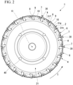
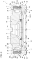
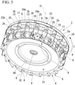
- the indexable milling cutter 1 includes the tool main body 2, a plurality of insert 30, and a plurality of adjustment units 50. As shown in Figs. 3 and 4 , the indexable milling cutter 1 includes the tool main body 2 and a plurality of position adjustment mechanisms 20, and each position adjustment mechanism 20 includes an insert 30 and an adjustment unit 50.
- the tool main body 2 has a substantially cylindrical shape centered on the center axis O.
- the tool main body 2 is mounted on a main spindle of a machine tool (not shown) and is rotated around the center axis O by the main spindle.
- the plurality of insert 30 are disposed at a distance from each other in a circumferential direction at an outer periphery of a front end part of the tool main body 2.
- Each insert 30 is referred to as a cutting insert or cutting tip.
- the insert 30 is detachably mounted at the outer periphery of the front end part of the tool main body 2.
- a plurality of insert mounting seats 4 are provided at a distance from each other in the circumferential direction at the outer periphery of the front end part of the tool main body 2.
- each insert 30 is detachably mounted on each insert mounting seat 4.
- the insert 30 has a cutting edge 7.
- the cutting edge 7 is disposed to protrude toward a fore-end and a radially outer side from the tool main body 2.
- the insert mounting seats 4 are provided at 10 or more spots (for example, 20 spots) at a distance from each other in the circumferential direction in the tool main body 2, and 10 or more (for example, 20) inserts 30 are also provided by the same number as the number of the insert mounting seats 4.
- the indexable milling cutter 1 is a so-called multi-blade type milling cutter.
- the multi-blade type is an exemplary example as the milling tool, but the tool is not necessarily limited to the multi-blade type.
- An upper portion of the tool main body 2 of the indexable milling cutter 1 is mounted on the main spindle of the machine tool.
- the tool main body 2 is moved in a direction (for example, orthogonal direction) intersecting the center axis O while being rotated in the tool rotation direction T of the center axis O by the main spindle. Then, milling task is performed on the work material by the cutting edges 7 of the plurality of inserts 30 mounted on the tool main body 2.
- a direction (a direction in which center axis O extends) along the center axis O of the tool main body 2 is referred to as an axial direction.
- a direction from a fitting portion 5 of the tool main body 2 mounted on the main spindle of the machine tool toward the insert mounting seat 4 and the insert 30 is referred to as a side with the tip portion, and a direction from the insert mounting seat 4 and the insert 30 to the fitting portion 5 is referred to as an aft-end.
- a direction orthogonal to the center axis O is referred to as a radial direction.
- a radial direction an orientation approaching the center axis O is referred to as a radially inner side, and an orientation away from the center axis O is referred to as a radially outer side.
- a direction orbiting around the center axis O is referred to as a circumferential direction.
- a circumferential direction an orientation in which the tool main body 2 is rotated by the main spindle of the machine tool during machining operation is referred to as the tool rotation direction T, and a rotation direction opposite to this orientation is referred to as a direction (or a tool counter-rotation direction) opposite to the tool rotation direction T.
- the tool main body 2 has an outer main body portion 21, an inner main body portion 22, a space portion 23, and a coolant hole 3. Additionally, the tool main body 2 has a chip pocket 6, the insert mounting seat 4, a support portion 24, and a depression portion 25. The chip pocket 6, the insert mounting seat 4, the support portion 24, and the depression portion 25 are disposed in the outer main body portion 21.
- a portion between the depression portions 25 lying next to each other in the circumferential direction (a portion 2b, which will be described below) is convex radially outward with respect to the depression portion 25.
- the depression portion 25 may be a continuous columnar surface in the circumferential direction. In this case, the depression portion 25 can be machined by a lathe.
- the outer main body portion 21 has a bottomed tubular shape.
- the outer main body portion 21 has a surrounding wall and a bottom wall.
- the outer main body portion 21 is made of, for example, a steel material.
- the inner main body portion 22 has a substantially columnar shape.
- the inner main body portion 22 is disposed inside the outer main body portion 21. That is, the inner main body portion 22 has a portion located inside the outer main body portion 21.
- the inner main body portion 22 is made of, for example, an aluminum material.
- the specific gravity of the inner main body portion 22 is smaller than the specific gravity of the outer main body portion 21.
- the inner main body portion 22 has a columnar portion 22a and a flange portion 22b.
- the fitting portion 5 is formed on a rear end surface (upper surface) of the columnar portion 22a.
- the fitting portion 5 is a hole that opens to the rear end surface of the columnar portion 22a and is recessed from the rear end surface to the side with the tip portion. The main spindle of the machine tool is inserted into the fitting portion 5.
- the flange portion 22b spreads radially outward from a rear end portion (upper end portion) of the columnar portion 22a.
- the flange portion 22b has a circular ring plate shape.
- a tip surface (lower surface) of the flange portion 22b faces a rear end surface (upper surface) of the surrounding wall of the outer main body portion 21.
- a portion adjacent to the side with the tip portion of the flange portion 22b on an outer peripheral surface of the columnar portion 22a is fitted into a rear end opening of the surrounding wall of the outer main body portion 21.
- An outer peripheral end portion and an inner peripheral end portion on the tip surface of the columnar portion 22a come into contact with a rear end surface of the bottom wall of the outer main body portion 21 from the aft-end.
- the columnar portion 22a and the bottom wall of the outer main body portion 21 are fastened by a screw member 40 and fixed to each other.
- the space portion 23 is located between the outer main body portion 21 and the inner main body portion 22.
- the space portion 23 is a thinned space provided inside the tool main body 2.
- the space portion 23 has a first space portion 23a and a second space portion 23b.
- the first space portion 23a is disposed between the surrounding wall of the outer main body portion 21 and the outer peripheral surface of the columnar portion 22a.
- the first space portion 23a is a cylindrical space centered on the center axis O.
- the second space portion 23b is disposed between the bottom wall of the outer main body portion 21 and the tip surface of the columnar portion 22a.
- the second space portion 23b is a circular ring-shaped space centered on the center axis O.
- the second space portion 23b is located between the outer peripheral end portion and the inner peripheral end portion on the tip surface of the columnar portion 22a.
- the second space portion 23b constitutes a portion of a passage of the coolant hole 3.
- the coolant hole 3 extends inside the tool main body 2.
- the coolant hole 3 penetrates the tool main body 2.
- the coolant (cutting fluid) supplied through a main spindle of a machine tool flows inside the coolant hole 3.
- the coolant hole 3 has a first coolant hole 3a, a second coolant hole 3b, and the second space portion 23b.
- the first coolant hole 3a penetrates the inner main body portion 22.
- the first coolant hole 3a opens to an inner peripheral surface of the fitting portion 5 and the tip surface of the columnar portion 22a.
- a tip portion of the first coolant hole 3a is connected to the second space portion 23b.
- a plurality (for example, four) of the first coolant holes 3a are provided at a distance from each other in the circumferential direction.
- the second coolant hole 3b penetrates the outer main body portion 21.
- the second coolant hole 3b opens to the rear end surface of the bottom wall of the outer main body portion 21 and an outer peripheral surface of the surrounding wall.
- a rear end portion of the second coolant hole 3b is connected to the second space portion 23b.
- a tip portion (radially outer end portion) of the second coolant holes 3b opens to the chip pocket 6.
- the tip portion of the second coolant hole 3b opens toward the cutting edge 7 of the insert 30.
- the plurality of second coolant holes 3b are provided at a distance from each other in the circumferential direction.
- the number of second coolant holes 3b is the same (for example, 20) as the number of chip pockets 6 and the number of inserts 30.
- a plurality of chip pockets 6 are provided at a distance from each other in the circumferential direction at the outer periphery of the front end part of the tool main body 2 (outer main body portion 21).
- Each chip pocket 6 is formed by being recessed in a concave shape at the outer periphery of the front end part of the tool main body 2.
- the insert mounting seat 4 is disposed adjacent to the chip pocket 6 in the direction opposite to the tool rotation direction T, in the outer periphery of the front end part of the tool main body 2 (outer main body portion 21). In other words, the chip pocket 6 is disposed adjacent to the insert mounting seat 4 in the tool rotation direction T.
- the insert mounting seat 4 has a rectangular hole shape or a groove shape, corresponding to the shape of the insert 30.
- the insert 30 is a face milling insert used for, for example, the face milling task (face milling).
- the insert 30 is mounted on the tool main body 2 with a tip portion 31t directed to the axial side with the tip portion.
- the plurality of inserts 30 mounted on the tool main body 2 only one type in which the shapes of the cutting edges 7 are same as each other may be used, or a plurality of types in which the shapes of the cutting edges 7 are different from each other may be used.
- the insert 30 has an insert body 31 mounted on the insert mounting seat 4 of the tool main body 2, the cutting edge 7 that extends along an intersecting ridge line between a rake face 32 and a flank face 33 of the insert body 31 and is disposed at the outer periphery of the tip of the insert body 31, a thinned portion 60, and a clamp recess part 37.
- the insert body 31 has a polygonal plate shape.
- the insert body 31 has a rectangular plate shape.
- the longitudinal direction of a rectangular surface (a polygonal surface, a main surface 31f, and a back surface 31g) of the insert body 31 is disposed along the axial direction of the tool main body 2 (refer to Fig. 2 ).
- a short-length direction of the rectangular surface of the insert body 31 is disposed in the radial direction of the tool main body 2 (refer to Fig. 1 ).
- the insert body 31 has a rectangular plate-shaped base metal portion 34 and a triangular plate-shaped cutting portion 35 joined to one corner of the base metal portion 34 to form a cutting edge 7.
- the base metal portion 34 is made of, for example, a cemented carbide.
- the cutting portion 35 is made of an ultra-high pressure sintered material such as a diamond sintered material or a cBN sintered material having a hardness higher than that of the base metal portion 34.
- the present invention is not limited to this, and the entire insert body 31 including the base metal portion 34 and the cutting portion 35 is made of, for example, cemented carbide and may be integrally formed of a single member.
- the cutting portion 35 is disposed at one corner of one polygonal surface (main surface 31f) out of a pair of polygonal surfaces (rectangular surfaces) constituting the main surface and the back surface of the insert body 31 and joined to the base metal portion 34 by brazing, integral sintering, or the like.
- the corner is a corner located at the outer periphery of the tip of the indexable milling cutter 1 when the insert 30 has been mounted on the insert mounting seat 4. Therefore, the corner is a corner of the tip portion 31t.
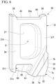
- the clamp recess part 37 recessed in the thickness direction from the main surface 31f is formed on the main surface 31f that is one polygonal surface of the base metal portion 34.
- the clamp recess part 37 has a D shape in a plan view of the insert 30 as viewed from the thickness direction.
- the clamp recess part 37 is not limited to the D shape in a plan view.
- the depth of the clamp recess part 37 becomes deeper from an end portion on a side opposite to the cutting portion 35 toward the cutting portion 35 in the short-length direction of the insert body 31. That is, a bottom surface of the clamp recess part 37 is an inclined surface.
- a rib 38 protruding in the thickness direction from the polygonal surface is formed at a portion located between the clamp recess part 37 and the cutting portion 35.
- the rib 38 extends linearly substantially parallel to an oblique side of the cutting portion 35 having a substantially right-angled triangular shape.
- the rib 38 is disposed so as to face the cutting portion 35 from the longitudinal direction and the short-length direction of the insert body 31. For this reason, when the insert 30 has been mounted on the insert mounting seat 4, the rib 38 is disposed so as to face the cutting edge 7 from an axially aft-end and from the radially inner side. Chips generated by cutting the work material by the cutting edge 7 come into contact with the rib 38.
- the thickness of the insert 30 becomes thicker from the cutting portion 35 toward the end portion on a side opposite to the cutting portion 35 in the short-length direction of the insert body 31. That is, when the insert 30 has been mounted on the insert mounting seat 4, the thickness of the insert 30 increases radially inward.
- the axial rake (axial rake angle) of the cutting edge 7 is a positive angle.
- the portion of the cutting edge 7 that extends in the short-length direction of the insert body 31 is a front edge 7a.
- the front edge 7a has a linear shape.
- the front edge 7a is not limited to the linear shape and may be, for example, a convex curve shape having a large curvature radius.
- the portion of the cutting edge 7 that extends in the longitudinal direction of the insert body 31 is a peripheral cutting edge 7b.
- the peripheral cutting edge 7b has a linear shape. When the insert 30 has been mounted on the insert mounting seat 4, the peripheral cutting edge 7b protrudes from the insert mounting seat 4 toward a radially outer side of the tool main body 2.
- the portion of the cutting edge 7 located between the front edge 7a and the peripheral cutting edge 7b is a corner edge 7c.
- the corner edge 7c has a convex curve shape or a linear shape.
- the insert 30 has a centrifugal force receiving portion 36.
- the centrifugal force receiving portion 36 is capable of supporting the adjustment unit 50 radially inward.
- the centrifugal force receiving portion 36 is capable of supporting the nut member 52 (to be described below) of the adjustment unit 50 radially inward.
- the centrifugal force receiving portion 36 receives a centrifugal force acting on the adjustment unit 50 during machining operation (a force directed to the radially outer side of the tool) from the radially outer side.
- a centrifugal force acting on the adjustment unit 50 during machining operation a force directed to the radially outer side of the tool
- the centrifugal force receiving portion 36 is disposed at a rear end portion of the insert 30 (insert body 31).
- the centrifugal force receiving portion 36 is provided at the rear end portion of the insert 30 and is capable of supporting the tip portion of the adjustment unit 50 radially inward. In the present embodiment, the centrifugal force receiving portion 36 abuts to the adjustment unit 50 in the radial direction. The centrifugal force receiving portion 36 abuts to the adjustment unit 50 from the radially outer side. In the example of the present embodiment, the centrifugal force receiving portion 36 also abuts to the adjustment unit 50 in the axial direction. The centrifugal force receiving portion 36 abuts to the adjustment unit 50 from the side with the tip portion.
- the centrifugal force receiving portion 36 is disposed on a rear end surface 30a of the insert 30 (insert body 31).
- the rear end surface 30a is an inclined surface that extends toward the side with the tip portion as approaching a radially inner side.
- the centrifugal force receiving portion 36 is also an inclined surface that extends toward the side with the tip portion as approaching the radially inner side.
- the centrifugal force receiving portion 36 is an inclined surface that extends radially inward as approaching the side with the tip portion.
- the centrifugal force receiving portion 36 is located radially outside a center line C of the adjustment unit 50 to be described below.
- the centrifugal force receiving portion 36 is located at a radially outer end portion of the rear end surface 30a.
- the insert 30 has a contact portion 39.
- the contact portion 39 is located radially inside the centrifugal force receiving portion 36 on the rear end surface 30a of the insert 30.
- the contact portion 39 is an inclined surface that extends radially outward as approaching the side with the tip portion.
- the contact portion 39 is located radially inside the center line C of the adjustment unit 50 to be described below.
- the contact portion 39 is located at the radially outer end portion of the rear end surface 30a.
- the contact portion 39 functions as a portion of a pressed surface that receives a pressing force directed from the adjustment unit 50 toward the axial side with the tip portion. Accordingly, the pressing force from the adjustment unit 50 can be received in a wide range (multiple spots) of the rear end surface 30a of the insert 30.
- the rear end surface 30a has a planar shape that spreads in a direction perpendicular to the center line C. Therefore, the pressing balance from the nut member 52 to the insert 30 is stable.
- the insert 30 has a recessed portion 43 that is recessed from the centrifugal force receiving portion 36 and the contact portion 39 of the insert 30 toward the side with the tip portion.
- the recessed portion 43 is located between the centrifugal force receiving portions 36 and the contact portions 39 at both radial end portions of the rear end surface 30a.
- a standing wall surface of an inner surface of the recessed portion 43 that faces radially inward is a second centrifugal force receiving portion (centrifugal force receiving portion) 44.
- the second centrifugal force receiving portion 44 has a planar shape that spreads in a direction perpendicular to the radial direction of the tool.
- the second centrifugal force receiving portion 44 extends from the bottom surface of the recessed portion 43 toward the aft-end.
- the insert 30 When a centrifugal force directed radially outward has acted on the adjustment unit 50, the insert 30 receives the centrifugal force at the second centrifugal force receiving portion 44.
- the insert 30 as described above has the thinned portion 60.
- the thinned portion 60 is provided at an axial tip portion 31t of the insert body 31.
- the thinned portion 60 is formed closer to the axial side with the tip portion than the clamp recess part 37 in the insert body 31.
- the thinned portion 60 is a thinned recessed portion 61 that is recessed in the thickness direction of the insert body 31 from the main surface 31f that is one polygonal surface of the insert body 31.
- the clamp recess part 37 and the thinned recessed portion 61 are formed at a distance from each other in the axial direction on the main surface 31f of the insert body 31.
- a beam-shaped portion 65 that extends in the short-length direction of the insert body 31 is formed between the clamp recess part 37 and the thinned recessed portion 61.
- the thinned recessed portion 61 opens toward the axial side with the tip portion on an end surface 31s of the insert body 31 on the axial side with the tip portion.
- the thinned recessed portion 61 reduces the weight of the insert 30.
- the weight of the insert 30 on the axial side with the tip portion is reduced.
- the center of gravity G of the insert body 31 is located in the clamp recess part 37 in a plan view.
- the thinned recessed portion 61 reduces the centrifugal force acting on the tip portion 31t of the insert body 31 when the centrifugal force acting radially outward has acted on the insert 30.
- the "plan view" of the insert 30 means a field viewed from a direction orthogonal to the rake face 32 of the insert body 31.
- the insert mounting seat 4 of the tool main body 2 will be described in detail.
- the insert mounting seat 4 opens to the tip surface and the outer peripheral surface of the tool main body 2 and extends in the axial direction.
- the insert mounting seat 4 has a first wall surface 8 that faces the direction opposite to the tool rotation direction T, a second wall surface 9 that faces the tool rotation direction T, a third wall surface 10 that is located at a radially inner end portion of the insert mounting seat 4 and faces radially outward, and a clamp screw hole 11.
- the first wall surface 8 has a planar shape that spreads along a virtual plane (not shown) including the center axis O of the tool main body 2, and the third wall surface 10 has a planar shape substantially orthogonal to the first wall surface 8.
- the second wall surface 9 extends in the tool rotation direction T as approaching the radially outer side. For this reason, the distance between the second wall surface 9 and the first wall surface 8 (the circumferential width of the insert mounting seat 4) becomes smaller as approaching the radially outer side.
- the insert 30 is inserted toward the axially aft-end with respect to the insert mounting seat 4.
- the main surface 31f facing the thickness direction of the insert 30 (one of the polygonal surfaces) abuts to the first wall surface 8.
- a slight gap is provided between the main surface 31f facing the thickness direction of the insert 30 and the first wall surface 8.
- the back surface 31g (other polygonal surface) facing the thickness direction of the insert 30 abuts to the second wall surface 9.
- the side surface 31h of the insert 30 facing the short-length direction abuts to the third wall surface 10.
- the insert 30 is sandwiched between the first wall surface 8 and the second wall surface 9 from the circumferential direction.
- the circumferential width of the insert mounting seat 4 becomes smaller as approaching the radially outer side.
- the radially outward movement of the insert 30 inserted into the insert mounting seat 4 with respect to the insert mounting seat 4 is suppressed. That is, it is possible to prevent the insert 30 from coming out of the insert mounting seat 4 radially outward.
- the insert 30 slidingly moves in the axial direction with respect to the insert mounting seat 4. That is, the insert 30 slidingly moves in the axial direction with respect to the tool main body 2.
- the clamp screw hole 11 opens to an outer peripheral surface (chip pocket 6) of the tool main body 2 and the first wall surface 8.
- a female thread portion is formed on an inner peripheral surface of the clamp screw hole 11.
- the clamp screw hole 11 extends radially inward in the direction opposite to the tool rotation direction T.
- a clamp screw 19 is screwed to the clamp screw hole 11 (refer to Fig. 3 ). As shown in Fig. 7 , a tip of the clamp screw 19 abuts to the bottom surface of the clamp recess part 37 of the insert 30.
- the insert 30 is fixed to the insert mounting seat 4 as the clamp screw 19 is screwed into the clamp screw hole 11.
- the plurality of adjustment units 50 are disposed at a distance from each other in the circumferential direction at an outer periphery of the tool main body 2 (outer main body portion 21).
- Each adjustment unit 50 presses the insert 30 toward the axial side with the tip portion to adjust the axial position of the insert 30.
- the adjustment unit 50 adjusts the axial position of the insert 30 with respect to the tool main body 2, thereby adjusting the axial position of the cutting edge 7.
- the number of adjustment units 50 is the same as the number of inserts 30. In the example of the present embodiment, 10 or more adjustment units 50 (for example, 20) are provided at the outer periphery of the tool main body 2.
- the adjustment unit 50 includes a shaft member 51 and a nut member 52.
- the shaft member 51 is supported by the tool main body 2.
- the shaft member 51 is screwed to the tool main body 2.
- the nut member 52 is screwed to the shaft member 51 and configured to be abutted to the insert 30.
- the center line C of the shaft member 51 extends in the axial direction of the tool main body 2. That is, the center line C of the adjustment unit 50 extends in the axial direction.
- the direction in which the center line C of the shaft member 51 extends corresponds to the axial direction of the tool main body 2.
- the shaft member 51 is rotated around the center line C with respect to the tool main body 2 (support portion 24) and thereby moved in the axial direction with respect to the tool main body 2 by the action of the screw.
- the nut member 52 is rotated around the center line C with respect to the shaft member 51 and the tool main body 2 and thereby moved in the axial direction with respect to the shaft member 51 and the tool main body 2 by the action of the screw.
- the shaft member 51 includes a first screw shaft 53 located at a rear end portion of the shaft member 51, a second screw shaft 54 located at a tip portion, and an operating portion 55 located between the first screw shaft 53 and the second screw shaft 54 in the axial direction.
- the outer diameter of the first screw shaft 53 is larger than the outer diameter of the second screw shaft 54.
- Male thread portions are respectively formed on an outer peripheral surface of the first screw shaft 53 and an outer peripheral surface of the second screw shaft 54.
- the male thread portion of the first screw shaft 53 and the male thread portion of the second screw shaft 54 have different thread pitches from each other. Specifically, the thread pitch of the male thread portion of the first screw shaft 53 is larger than the thread pitch of the male thread portion of the second screw shaft 54.
- the operating portion 55 has a columnar shape or a disk shape.
- the outer diameter of the operating portion 55 is larger than the outer diameter of the first screw shaft 53 and the outer diameter of the second screw shaft 54.
- a shaft operation hole 55a opens to an outer peripheral surface of the operating portion 55.
- a plurality of (for example, four at equal intervals) the shaft operation holes 55a are provided at a distance from each other around the center line C on the outer peripheral surface of the operating portion 55.
- the shaft operation hole 55a extends in a direction orthogonal to the center line C.
- the shaft operation hole 55a is formed so as to penetrate the operating portion 55 in the direction orthogonal to the center line C.
- a working tool such as a wrench (not shown) is inserted into the shaft operation hole 55a.
- the nut member 52 has a cylindrical or circular ring plate shape centered on the center line C.
- the outer diameter of the nut member 52 is larger than the outer diameter of the shaft member 51.
- a female thread portion is formed on the inner peripheral surface of the nut member 52.
- the nut member 52 is screwed to the second screw shaft 54.
- a nut operation hole 52a opens to an outer peripheral surface of the nut member 52.
- a plurality of (for example, five at equal intervals) the nut operation holes 52a are provided at a distance from each other around the center line C on the outer peripheral surface of the nut member 52.
- Each nut operation hole 52a extends in the direction orthogonal to the center line C.
- the nut operation hole 52a is a stop hole having a bottom portion.
- a working tool such as a wrench (not shown) is inserted into the nut operation hole 52a.
- the nut member 52 has the largest outer diameter in the adjustment unit 50.
- a radially outer end located most radially outside the tool main body 2 is a portion of the outer peripheral surface of the nut member 52.
- the radial position of the radially outer end of the adjustment unit 50 is radially inside the radial position of the radially outer end (peripheral cutting edge 7b) of the insert 30.
- a tip surface of the nut member 52 abuts to the rear end surface of the insert 30 from the aft-end.
- the axial position of the insert 30 is adjusted by adjusting either the screwing amount of the shaft member 51 with respect to the tool main body 2 or the screwing amount of the nut member 52 with respect to the shaft member 51 in a state where the clamp screw 19 is loosened or temporarily tightened. That is, the axial positions of the insert 30 and the cutting edge 7 with respect to the insert mounting seat 4 are adjustable by operating the working tool to rotate either the shaft member 51 or the nut member 52 around the center line C. After the position of the insert 30 is adjusted, the clamp screw 19 is screwed in and finally tightened, thereby fixing the insert 30 to the insert mounting seat 4.
- the axial position of the insert 30 may be minutely adjusted by adjusting either the screwing amount of the shaft member 51 with respect to the tool main body 2 or the screwing amount of the nut member 52 with respect to the shaft member 51 in a state where the clamp screw 19 is finally tightened.
- the nut member 52 has a convex tapered surface 52b whose diameter is reduced toward the side with the tip portion, on the tip surface of the nut member 52.
- the convex tapered surface 52b has a conical surface shape.
- the convex tapered surface 52b has a circular annular shape that extends over the entire circumference around the center line C on the tip surface of the nut member 52.
- the convex tapered surface 52b abuts to the centrifugal force receiving portion 36 and the contact portion 39 of the insert 30.
- the centrifugal force receiving portion 36 supports the convex tapered surface 52b radially inward.
- the centrifugal force receiving portion 36 abuts to the convex tapered surface 52b from the radially outer side.
- the centrifugal force receiving portion 36 and the contact portion 39 also function as a pressed surface that receives a pressing force directed from the adjustment unit 50 to the axial side with the tip portion.
- the nut member 52 has a protruding portion 58 at a tip portion of the nut member 52.
- the protruding portion 58 protrudes further toward the side with the tip portion than the convex tapered surface 52b.
- the protruding portion 58 has a pillar shape that extends in the axial direction.
- the protruding portion 58 has a columnar shape.
- the protruding portion 58 may have a polygonal pillar shape or the like.
- the protruding portion 58 is located in the recessed portion 43.
- the protruding portion 58 faces a second centrifugal force receiving portion 44 from the radially inner side.
- the second centrifugal force receiving portion 44 faces the outer peripheral surface of the protruding portion 58 with a gap in the radial direction. That is, the second centrifugal force receiving portion 44 faces the adjustment unit 50 with a gap in the radial direction.
- the second centrifugal force receiving portion 44 is capable of coming in contact with the adjustment unit 50 to support the adjustment unit 50 radially inward.
- a gap is provided between a tip surface of the protruding portion 58 and the bottom surface of the recessed portion 43 facing the aft-end.
- the insert 30 When a centrifugal force directed radially outward has acted on the adjustment unit 50, the insert 30 receives the centrifugal force at the second centrifugal force receiving portion 44. That is, the second centrifugal force receiving portion 44 of the recessed portion 43 is capable of supporting the protruding portion 58 radially inward.
- the support portion 24 is disposed on the axially aft-end of the adjustment unit 50 to support the adjustment unit 50.
- a plurality of the support portions 24 are disposed at a distance from each other in the circumferential direction on the outer peripheral surface of the tool main body 2.
- the number of support portions 24 is the same as the number of adjustment units 50.
- 10 or more (for example, 20) support portions 24 are provided at the outer periphery of the tool main body 2.
- the support portions 24 are disposed at a rear end portion of an outer peripheral surface of the surrounding wall of the outer main body portion 21.
- the support portion 24 has a rib shape that extends in the axial direction.
- the support portion 24 protrudes radially outward on the outer peripheral surface of the tool main body 2.
- the support portion 24 protrudes further radially outward than a portion 2a adjacent to the support portion 24 in the circumferential direction (a portion facing the circumferential direction), in the outer peripheral surface of the tool main body 2.
- the portion 2a may be paraphrased as the portion 2a located between the support portions 24 lying next to each other in the circumferential direction, in the outer peripheral surface of the tool main body 2.
- the support portion 24 protrudes further radially outward than a portion (depression portion 25) adjacent to the side with the tip portion of the support portion 24 on the outer peripheral surface of the tool main body 2.
- the support portion 24 has a screw hole 24a that extends in the axial direction.
- the screw hole 24a penetrates the support portion 24 in the axial direction and opens to the tip surface and the rear end surface of the support portion 24.
- a female thread portion is provided on an inner peripheral surface of the screw hole 24a.
- the first screw shaft 53 is screwed to the screw hole 24a.
- the support portion 24, the adjustment unit 50, the insert mounting seat 4, and the insert 30 are disposed so as to overlap each other.
- the radial position of the portion 2b between the adjustment units 50 lying next to each other in the circumferential direction in the outer peripheral surface of the tool main body 2 is radially inside the radial position of the adjustment unit 50.
- the adjustment unit 50 is disposed so as to protrude further radially outward than the portion 2b between the adjustment units 50 lying next to each other in the circumferential direction on the outer peripheral surface of the tool main body 2.
- the radial position of the portion 2b between the adjustment units 50 lying next to each other in the circumferential direction on the outer peripheral surface of the tool main body 2 is radially inside the radial position of the center line C of the adjustment unit 50.
- the portion 2b may be paraphrased as a portion (a portion facing the circumferential direction) 2b adjacent to the adjustment unit 50 in the circumferential direction on the outer peripheral surface of the tool main body 2.
- the portion 2b has an arc shape centered on the center axis O.
- the radial position of the portion 2b is radially outside the radial position of the portion other than the portion 2b. That is, in the axial region where the portion 2b is disposed, the portion 2b forms an outermost diameter portion of the outer peripheral surface of the tool main body 2. For this reason, when the tool main body 2 (outer main body portion 21) is manufactured, the portion 2b can be formed by turning.
- the radial position of the portion 2b between the adjustment units 50 lying next to each other in the circumferential direction on the outer peripheral surface of the tool main body 2 is radially outside the radial position of the portion 2a between the support portions 24 lying next to each other in the circumferential direction on the outer peripheral surface of the tool main body 2.
- the depression portion 25 is disposed at a position overlapping the adjustment unit 50 in the outer peripheral surface of the tool main body 2 (outer main body portion 21) and is recessed radially inward.
- the number of depression portions 25 is the same as the number of adjustment units 50. In the example of the present embodiment, 10 or more (for example, 20) depression portions 25 are provided at the outer periphery of the tool main body 2.
- the depression portion 25 has a rectangular hole shape.
- the depression portion 25 extends in the axial direction.
- the depression portion 25 is disposed adjacent to the portion 2b between the adjustment units 50 lying next to each other in the circumferential direction on the outer peripheral surface of the tool main body 2, in the circumferential direction.
- the depression portion 25 is disposed between the portions 2b lying next to each other in the circumferential direction on the outer peripheral surface of the tool main body 2.
- the depression portion 25 is disposed radially inside the portion 2b. In other words, the radial position of the portion 2b is radially outside than the radial position of the depression portion 25.
- a portion of the adjustment unit 50 is disposed in the depression portion 25.
- a portion (radially inner end portion) of the operating portion 55 and a portion (radially inner end portion) of the nut member 52 are located in the depression portion 25.
- a portion (radially inner end portion) of the operating portion 55, a portion (radially inner end portion) of the nut member 52, and the depression portion 25 are disposed so as to overlap each other.
- the tip portion 31t of the insert 30 becomes lighter. Accordingly, the position of the center of gravity G of the insert 30 approaches an axial aft-end (axial aft-end). Therefore, when the tool main body 2 has rotated around the center axis O, it is possible to suppress the radially outward displacement of the tip portion 31t of the insert 30 due to a centrifugal force. As a result, it is possible to increase the upper limit of the tool rotation speed.
- the thinned portion 60 is formed on the axial side with the tip portion with respect to the clamp recess part 37. Accordingly, the tip portion 31t of the insert 30 becomes lighter, and when the tool main body 2 has rotated around the center axis O, it is possible to suppress the radially outward displacement of the tip portion 31t of the insert 30 due to a centrifugal force.
- the center of gravity G of the insert body 31 is located in the clamp recess part 37. Accordingly, it is difficult for the insert body 31 to rotate around the position where the tip of the clamp screw 19 comes in contact due to a centrifugal force. Therefore, it is possible to suppress the radially outward displacement of the tip portion 31t of the insert 30 due to a centrifugal force.
- the thinned portion 60 opens to the end surface 31s of the insert body 31. Accordingly, the tip portion 31t of the insert 30 becomes lighter more effectively. Therefore, when the tool main body 2 has rotated around the center axis O, it is possible to more effectively suppress the radially outward displacement of the tip portion 31t of the insert 30 due to a centrifugal force.
- the insert 30 is detachably mounted on the outer periphery (insert mounting seat 4) of the front end part of the tool main body 2.
- the insert 30 is a detachable cutting insert or cutting tip. For this reason, when the insert 30 reaches the end of the tool life, the processing accuracy can be satisfactorily maintained by replacing the insert 30 with another new insert 30. Additionally, a plurality of types of inserts 30 having various cutting edges 7 can be prepared and selectively used in accordance with the type, the processing form, and the like of a work material.
- Fig. 9 is a perspective view of an insert 130 of a first modification example.
- components having the same aspects as those in the above-described embodiment are designated by the same reference numerals, and the description thereof will be omitted.
- a thinned portion 160 formed in the insert 130 has a thinned recessed portion 162.
- the thinned recessed portion 162 is formed on the axial aft-end (axial aft-end) than the end surface 31s of the tip portion 31t of the insert body 31. That is, the thinned recessed portion 162 does not open from the end surface 31s of the insert body 31 to the axial side with the tip portion.
- the thinned recessed portion 162 is formed as the thinned portion 160. Accordingly, the tip portion 31t of the insert 130 is lighter, the position of the center of gravity G of the insert 130 is closer to the axial aft-end (axial aft-end). Therefore, when the tool main body 2 has rotated around the center axis O, it is possible to suppress the radially outward displacement of the tip portion 31t of the insert 130 due to a centrifugal force. As a result, it is possible to increase the upper limit of the tool rotation speed.
- Figs. 10 and 11 are perspective views of an insert 230 of a second modification example.
- components having the same aspects as those in the above-described embodiment are designated by the same reference numerals, and the description thereof will be omitted.
- a thinned portion 260 formed in the insert 230 has a thinned recessed portion 263.
- the thinned recessed portion 263 is disposed at the tip portion 31t of the insert body 31.
- the thinned recessed portion 263 is recessed in the thickness direction of the insert body 31 from the back surface 31g of the insert body 31.
- the thinned recessed portion 263 is formed closer to the axial side with the tip portion than the clamp recess part 37 formed on the main surface 31f in the insert body 31.
- the clamp recess part 37 and the thinned recessed portion 263 are formed at a distance from each other in the axial direction.
- the thinned recessed portion 263 is formed as the thinned portion 260. Accordingly, the tip portion 31t of the insert 230 is lighter, the position of the center of gravity G of the insert 230 is closer to the axial aft-end (axial aft-end). Therefore, when the tool main body 2 has rotated around the center axis O, it is possible to suppress the radially outward displacement of the tip portion 31t of the insert 230 due to a centrifugal force. As a result, it is possible to increase the upper limit of the tool rotation speed.
- the insert 30 includes the adjustment unit 50, but the present invention is not limited to this.
- the insert 30 may be mounted on the tool main body 2 so that the position thereof cannot be adjusted in the axial direction.
- the nut member 52 abuts to the insert 30 on the convex tapered surface 52b, but the convex tapered surface 52b may face the insert 30 via a gap. In this case, the nut member 52 abuts to the insert 30 at another portion.
- the cutting insert and the milling tool of the present invention it is possible to suppress the radially outward displacement of the cutting insert due to a centrifugal force and increase the upper limit of the tool rotation speed.
Landscapes
- Engineering & Computer Science (AREA)
- Mechanical Engineering (AREA)
- Milling Processes (AREA)
Applications Claiming Priority (2)
| Application Number | Priority Date | Filing Date | Title |
|---|---|---|---|
| JP2019068362A JP7156139B2 (ja) | 2019-03-29 | 2019-03-29 | 切削インサートおよび転削工具 |
| PCT/JP2020/012995 WO2020203463A1 (fr) | 2019-03-29 | 2020-03-24 | Insert de coupe et outil de coupe rotatif |
Publications (2)
| Publication Number | Publication Date |
|---|---|
| EP3950198A1 true EP3950198A1 (fr) | 2022-02-09 |
| EP3950198A4 EP3950198A4 (fr) | 2022-12-07 |
Family
ID=72669070
Family Applications (1)
| Application Number | Title | Priority Date | Filing Date |
|---|---|---|---|
| EP20784415.0A Pending EP3950198A4 (fr) | 2019-03-29 | 2020-03-24 | Insert de coupe et outil de coupe rotatif |
Country Status (4)
| Country | Link |
|---|---|
| EP (1) | EP3950198A4 (fr) |
| JP (1) | JP7156139B2 (fr) |
| CN (1) | CN113631309B (fr) |
| WO (1) | WO2020203463A1 (fr) |
Families Citing this family (2)
| Publication number | Priority date | Publication date | Assignee | Title |
|---|---|---|---|---|
| US20220371110A1 (en) * | 2020-10-29 | 2022-11-24 | Sumitomo Electric Hardmetal Corp. | Cutting tool |
| WO2024095399A1 (fr) * | 2022-11-02 | 2024-05-10 | 住友電気工業株式会社 | Outil de coupe |
Family Cites Families (12)
| Publication number | Priority date | Publication date | Assignee | Title |
|---|---|---|---|---|
| JPS60221211A (ja) * | 1985-01-13 | 1985-11-05 | Daijietsuto Kogyo Kk | 転削工具 |
| JPH10277828A (ja) * | 1997-03-31 | 1998-10-20 | Mitsubishi Materials Corp | 転削工具 |
| JP4378931B2 (ja) * | 2002-03-04 | 2009-12-09 | 三菱マテリアル株式会社 | 刃部交換式切削工具及びこれに装着される刃部 |
| JP2008023632A (ja) * | 2006-07-19 | 2008-02-07 | Mitsubishi Materials Corp | 切削工具及びインサート |
| JP5024189B2 (ja) * | 2008-06-04 | 2012-09-12 | 株式会社タンガロイ | チップの仮止め機構およびこれを備えたスローアウェイ式切削工具 |
| KR101105058B1 (ko) * | 2009-05-07 | 2012-01-13 | 대구텍 유한회사 | 절삭 공구 및 절삭 공구용 인서트 |
| JP5589244B2 (ja) * | 2010-10-06 | 2014-09-17 | 大昭和精機株式会社 | インサート |
| JP2014083667A (ja) | 2012-10-26 | 2014-05-12 | Mitsubishi Materials Corp | 切削インサートおよび刃先交換式切削工具 |
| JP6264767B2 (ja) | 2013-07-30 | 2018-01-24 | 三菱マテリアル株式会社 | 刃先交換式フライス |
| EP3167991A4 (fr) * | 2014-07-10 | 2017-07-26 | Sumitomo Electric Hardmetal Corp. | Plaquette de coupe et fraise à lames rapportées |
| EP3072616B1 (fr) | 2015-03-25 | 2018-10-10 | Sandvik Intellectual Property AB | Insert de coupe et outil de fraisage |
| JP6920163B2 (ja) | 2017-10-04 | 2021-08-18 | アイホン株式会社 | インターホンシステム |
-
2019
- 2019-03-29 JP JP2019068362A patent/JP7156139B2/ja active Active
-
2020
- 2020-03-24 WO PCT/JP2020/012995 patent/WO2020203463A1/fr not_active Ceased
- 2020-03-24 CN CN202080024071.9A patent/CN113631309B/zh active Active
- 2020-03-24 EP EP20784415.0A patent/EP3950198A4/fr active Pending
Also Published As
| Publication number | Publication date |
|---|---|
| CN113631309A (zh) | 2021-11-09 |
| JP2020163544A (ja) | 2020-10-08 |
| CN113631309B (zh) | 2024-05-31 |
| JP7156139B2 (ja) | 2022-10-19 |
| WO2020203463A1 (fr) | 2020-10-08 |
| EP3950198A4 (fr) | 2022-12-07 |
Similar Documents
| Publication | Publication Date | Title |
|---|---|---|
| US8172487B2 (en) | Milling cutter and cutting insert therefor | |
| US11273499B2 (en) | Turning insert | |
| WO2013027211A1 (fr) | Outil de coupe et plaquette de coupe munie d'un trou de serrage comportant des parties de serrage espacées | |
| US11517967B2 (en) | Whirling tool | |
| JP4816496B2 (ja) | 穴加工工具 | |
| CN102143816A (zh) | 侧铣刀 | |
| EP3950198A1 (fr) | Insert de coupe et outil de coupe rotatif | |
| JP4227955B2 (ja) | 切削工具 | |
| JP2009061587A (ja) | インサート | |
| JP7043933B2 (ja) | 切刃部の位置調整機構および転削工具 | |
| JP7131893B2 (ja) | ステップ式フライスカッタ | |
| CN116600923B (zh) | 用于切削加工的工具及切削刀具在该工具上的使用 | |
| JP6467048B2 (ja) | 切削工具及び切削加工物の製造方法 | |
| US8641334B2 (en) | Insert | |
| JP7243001B2 (ja) | 転削工具 | |
| JP7045460B2 (ja) | 切削工具及び切削加工物の製造方法 | |
| JP7167468B2 (ja) | 転削工具 | |
| JP7020245B2 (ja) | 切刃部の位置調整機構および転削工具 | |
| JP7556824B2 (ja) | ボーリング工具 | |
| US20180304387A1 (en) | Cutting tool and cutting insert | |
| JP2007130739A (ja) | 穴加工工具 | |
| JP2024109138A (ja) | 転削工具 | |
| JP2019123045A (ja) | 回転切削工具及び切りくず分断部材 | |
| JP2019206062A (ja) | 回転切削工具及び切りくず分断部材 | |
| JP2007320021A (ja) | 穴加工工具 |
Legal Events
| Date | Code | Title | Description |
|---|---|---|---|
| STAA | Information on the status of an ep patent application or granted ep patent |
Free format text: STATUS: THE INTERNATIONAL PUBLICATION HAS BEEN MADE |
|
| PUAI | Public reference made under article 153(3) epc to a published international application that has entered the european phase |
Free format text: ORIGINAL CODE: 0009012 |
|
| STAA | Information on the status of an ep patent application or granted ep patent |
Free format text: STATUS: REQUEST FOR EXAMINATION WAS MADE |
|
| 17P | Request for examination filed |
Effective date: 20211020 |
|
| AK | Designated contracting states |
Kind code of ref document: A1 Designated state(s): AL AT BE BG CH CY CZ DE DK EE ES FI FR GB GR HR HU IE IS IT LI LT LU LV MC MK MT NL NO PL PT RO RS SE SI SK SM TR |
|
| DAV | Request for validation of the european patent (deleted) | ||
| DAX | Request for extension of the european patent (deleted) | ||
| A4 | Supplementary search report drawn up and despatched |
Effective date: 20221107 |
|
| RIC1 | Information provided on ipc code assigned before grant |
Ipc: B23C 5/06 20060101ALI20221031BHEP Ipc: B23C 5/24 20060101ALI20221031BHEP Ipc: B23C 5/22 20060101ALI20221031BHEP Ipc: B23C 5/20 20060101AFI20221031BHEP |