EP3950199A1 - Outil de taraud et procédé de coulée - Google Patents
Outil de taraud et procédé de coulée Download PDFInfo
- Publication number
- EP3950199A1 EP3950199A1 EP20782099.4A EP20782099A EP3950199A1 EP 3950199 A1 EP3950199 A1 EP 3950199A1 EP 20782099 A EP20782099 A EP 20782099A EP 3950199 A1 EP3950199 A1 EP 3950199A1
- Authority
- EP
- European Patent Office
- Prior art keywords
- tap
- rotation
- axis
- tap tool
- tool
- Prior art date
- Legal status (The legal status is an assumption and is not a legal conclusion. Google has not performed a legal analysis and makes no representation as to the accuracy of the status listed.)
- Pending
Links
Images





Classifications
-
- B—PERFORMING OPERATIONS; TRANSPORTING
- B23—MACHINE TOOLS; METAL-WORKING NOT OTHERWISE PROVIDED FOR
- B23G—THREAD CUTTING; WORKING OF SCREWS, BOLT HEADS, OR NUTS, IN CONJUNCTION THEREWITH
- B23G5/00—Thread-cutting tools; Die-heads
- B23G5/02—Thread-cutting tools; Die-heads without means for adjustment
- B23G5/06—Taps
-
- B—PERFORMING OPERATIONS; TRANSPORTING
- B23—MACHINE TOOLS; METAL-WORKING NOT OTHERWISE PROVIDED FOR
- B23G—THREAD CUTTING; WORKING OF SCREWS, BOLT HEADS, OR NUTS, IN CONJUNCTION THEREWITH
- B23G1/00—Thread cutting; Automatic machines specially designed therefor
- B23G1/16—Thread cutting; Automatic machines specially designed therefor in holes of workpieces by taps
- B23G1/18—Machines with one working spindle
-
- B—PERFORMING OPERATIONS; TRANSPORTING
- B23—MACHINE TOOLS; METAL-WORKING NOT OTHERWISE PROVIDED FOR
- B23G—THREAD CUTTING; WORKING OF SCREWS, BOLT HEADS, OR NUTS, IN CONJUNCTION THEREWITH
- B23G5/00—Thread-cutting tools; Die-heads
- B23G5/02—Thread-cutting tools; Die-heads without means for adjustment
- B23G5/06—Taps
- B23G5/062—Taps with a guiding means part
-
- B—PERFORMING OPERATIONS; TRANSPORTING
- B23—MACHINE TOOLS; METAL-WORKING NOT OTHERWISE PROVIDED FOR
- B23G—THREAD CUTTING; WORKING OF SCREWS, BOLT HEADS, OR NUTS, IN CONJUNCTION THEREWITH
- B23G2240/00—Details of equipment for threading other than threading tools, details of the threading process
- B23G2240/12—Means for cooling or lubrication
-
- Y—GENERAL TAGGING OF NEW TECHNOLOGICAL DEVELOPMENTS; GENERAL TAGGING OF CROSS-SECTIONAL TECHNOLOGIES SPANNING OVER SEVERAL SECTIONS OF THE IPC; TECHNICAL SUBJECTS COVERED BY FORMER USPC CROSS-REFERENCE ART COLLECTIONS [XRACs] AND DIGESTS
- Y10—TECHNICAL SUBJECTS COVERED BY FORMER USPC
- Y10T—TECHNICAL SUBJECTS COVERED BY FORMER US CLASSIFICATION
- Y10T408/00—Cutting by use of rotating axially moving tool
- Y10T408/03—Processes
-
- Y—GENERAL TAGGING OF NEW TECHNOLOGICAL DEVELOPMENTS; GENERAL TAGGING OF CROSS-SECTIONAL TECHNOLOGIES SPANNING OVER SEVERAL SECTIONS OF THE IPC; TECHNICAL SUBJECTS COVERED BY FORMER USPC CROSS-REFERENCE ART COLLECTIONS [XRACs] AND DIGESTS
- Y10—TECHNICAL SUBJECTS COVERED BY FORMER USPC
- Y10T—TECHNICAL SUBJECTS COVERED BY FORMER US CLASSIFICATION
- Y10T408/00—Cutting by use of rotating axially moving tool
- Y10T408/89—Tool or Tool with support
- Y10T408/904—Tool or Tool with support with pitch-stabilizing ridge
- Y10T408/9046—Tool or Tool with support with pitch-stabilizing ridge including tapered section
- Y10T408/90467—Tool or Tool with support with pitch-stabilizing ridge including tapered section and relieved cutting edge
Definitions
- the present invention relates to a tap tool for machining a pilot hole provided in a workpiece into a screw hole, and a tap machining method.
- synchronous tap machining in which rotation and linear feeding are synchronized, is performed.
- Synchronous tap machining also requires synchronization of rotation and feeding when withdrawing the tap tool from the machined screw hole.
- the time required for withdrawal of the tap tool is substantially equal to the time required to advance the tap tool and machine the threaded groove.
- a machining program creator selects a tool material suitable for the work material and optimizes the rotation speed of the spindle of the machining center in accordance with the torque characteristics of the spindle motor of the machining center and the diameter and depth of the screw hole in order to attempt to achieve a reduction of tap machining time in minute units of, for example, less than 1 second.
- Patent Literature 1 discloses a tap tool (thread milling machine) used along with NC milling machines or machining centers.
- the tap tool of Patent Literature 1 is formed so as to enable not only tap machining but also the machining of pilot holes at the same time as tap machining in order to comprehensively reduce the machining time.
- the tap tool of Patent Literature 1 comprises a bottom blade for performing pilot hole machining and a tip, which is a blade section for tap machining, on the outer periphery of the tool.
- the tap tool has an outer diameter which is considerably smaller than the inner diameter of the screw hole to be machined, and tap machining is performed by rotating (turning) the tap tool about the spindle of the machine tool and revolving about the central axis of the screw hole.
- the tap tool of Patent Literature 1 since the outer diameter of the tap tool is smaller than the inner diameter of the screw hole, bending stress based on cutting resistance is generated in the tap tool during tap machining. As a result, there is a concern that the dimensional accuracy of the screw hole may be reduced due to deflection of the tap tool, in particular when the tap tool is elongate. Furthermore, since the tap machining of Patent Literature 1 is performed with one tip, it is expected that the tap machining time will increase as compared to the conventional tap tools of the prior art, and as a result, the effect on the conventional tap machining methods of the prior art is considered to be limited when compared in terms of machining time including pilot hole machining.
- the present invention has been conceived in light of such circumstances, and an object of the present invention is to provide a tap tool with which tap machining can be performed in a short time while maintaining the same accuracy as the prior art.
- a tap tool which has an axis of rotation and which machines a pilot hole provided in a workpiece into a screw hole in a state in which a central axis of the pilot hole and the axis of rotation are aligned
- the tap tool comprising a thread section having a blade section which machines a threaded groove of the screw hole, a pad section which is positioned rearward of the blade section in the direction of rotation and which engages with the threaded groove machined by the blade section during machining of the threaded groove, and a non-engagement section which forms a space between itself and the screw hole in a cross-sectional view in which the axis of rotation and the central axis of the screw hole are aligned, wherein the space has a size which enables simultaneous release of engagement between the thread section and the threaded groove and engagement between the pad section and the threaded groove when the tap tool shifts in the screw hole in a direction orthogonal to the axis
- a tap machining method comprising the steps of aligning an axis of rotation of a spindle of a machine tool on which a tap tool is installed and a central axis of a pilot hole provided in a workpiece, performing tap machining on the pilot hole by advancing the tap tool in the direction of the axis of rotation while rotating the tap tool, shifting the tap tool in a direction orthogonal to the axis of rotation of the spindle so as to release engagement between a thread section of the stationary tap tool, which has a blade section, and a threaded groove of a screw hole formed in the workpiece, and withdrawing the tap tool in the direction of the axis of rotation without rotating the tap tool.
- the tap tool after machining, it is possible to retract the tap tool, which has been moved in a direction orthogonal to the axis of rotation and for which engagement with the threaded groove of the screw hole has been released, from the screw hole in the direction of the axis of rotation at high speed without rotating the tap tool. Due to the effect of retracting at high speed, the machining time including the time for returning to the machining start point can be shortened.
- the deflection which occurs in the tap tool based on the cutting resistance is negligible, and as a result, machining accuracy is similar to the case in which the conventional tap tool 210 of the prior art is used.
- FIG. 1 is a diagram showing a machine tool 100, which is a conventional vertical machining center, and a tap tool 10 according to an embodiment of the present invention mounted on the machine tool 100.
- the machine tool 100 of FIG. 1 comprises a bed 102 serving as a base affixed to a floor of a factory, a Y-axis slider 104 which is provided on the upper surface of the bed 102 so as to be movable in the Y-axis direction and to which a workpiece 8 is clamped and affixed, a column 108 which stands on the upper surface of the bed 102, on the right side in FIG.
- an X-axis slider 110 which is provided so as to be movable in the X-axis direction (the direction perpendicular to the sheet of FIG. 1 ) on the front surface of the column 108
- a Z-axis slider 112 which is provided so as to be movable in the Z-axis direction relative to the X-axis slider 110
- a spindle head 116 affixed to the Z-axis slider 112 and supporting the spindle 114 so as to be capable of rotating about a vertical axis of rotation C r . Since the machine tool 100 is configured in this manner, the spindle head 116 can be moved and positioned relative to the workpiece 8.
- the machine tool 100 also includes a controller 120 and an automatic tool exchange device (not illustrated).
- the machine tool 100 executes tap machining as a so-called "synchronous tap machining", i.e., machining in which the rotation of the spindle 114 and the feeding in the Z-axis direction are synchronized.
- synchronous tap machining i.e., machining in which the rotation of the spindle 114 and the feeding in the Z-axis direction are synchronized.
- linear movement in the Z-axis direction in which the tap tool 10 executes tap machining is also referred to as advancing
- linear movement in the Z-axis direction in which the tap tool 10 is retracted from the screw hole 6 is also referred to as withdrawal. Since the axis of rotation C r of the spindle 114 and the axis of rotation C r of the tap tool are always aligned, the same reference numerals are assigned to them in the present specification.
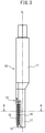
- FIG. 2 A perspective view of the tap tool 10 according to the embodiment of the present invention is shown in FIG. 2 , a front view is shown in FIG. 3 , and a cross-sectional view taken along cutting line A-A of FIG. 3 immediately after machining is shown in FIG. 4 together with the screw hole 6.
- the tap tool 10 performs tap machining, i.e., machining in which a pilot hole 6' is formed into a screw hole 6, in a state in which the axis of rotation C r is aligned with the central axis C 6 of the pilot hole 6' provided in the workpiece.
- tap machining i.e., machining in which a pilot hole 6' is formed into a screw hole 6, in a state in which the axis of rotation C r is aligned with the central axis C 6 of the pilot hole 6' provided in the workpiece.
- the circle represented by reference sign 6a corresponds to the inner diameters of the pilot hole 6' and the screw hole 6, and the circle represented by reference sign 6b corresponds to the root diameter of the threads of the screw hole 6, i.e., the nominal diameter of the tap tool 10.
- the tap tool 10 comprises a shank section 11 on a proximal end side and a machining section 12 on a distal end side.
- a tapered section 13 is provided at the tip of the machining section 12.
- the machining section 12 is asymmetrically formed with respect to the axis of rotation C r and comprises a thread section 14 in the form of a male thread that has multiple blade sections 14a that machine the threaded grooves of screw hole 6, pad sections 15, 16 in the form of male threads which engage with the threaded grooves machined by the blade sections 14a, and a non-engagement section 17 which does not contact the pilot hole 6' or the screw hole 6 during machining.
- the thread section 14 has a plurality of threads arranged at predetermined pitches in the longitudinal direction, and the blade sections 14a are provided on the front sides of the respective threads in the direction of rotation.
- the tap tool 10 forms the threaded grooves of a triangular thread.
- FIG. 7 shows a conventional tap tool 210 of the prior art for comparison.
- the tap tool 210 has four thread sections 214 having blade sections 214a for cutting, which are divided by four longitudinal grooves 218 for cutting oil flow.
- the four thread sections 214 are arranged at 90-degree intervals in a cross-sectional view.
- one thread section 14 is arranged only in the approximately 8-o'clock to 9-o'clock direction in FIG. 4 .
- the one thread section 14 of the tap tool 10 of FIG. 4 can machine a threaded groove by means of the blade sections 14a in the same manner as the conventional thread sections 214 of, for example, FIG. 7 .
- the principle of cutting by means of the blade sections 14a is the same as that of the prior art, and thus, the blade sections 14a each have a rake face 14b, in the same manner as the prior art.
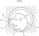
- FIG. 5 which is a cross-sectional view identical to FIG.
- the tap tool 10 is formed so as to rotate clockwise.
- the pad sections 15, 16 are provided rearward in the direction of rotation of the thread section 14, and in the present embodiment, two pad sections, i.e., a first pad section 15 and a second pad section 16, are provided.
- a first groove 18 is provided between the first pad section 15 and the thread section 14, and a second groove 19 is provided between the first pad section 15 and the second pad section 16. Since the first groove 18 and the second groove 19 are formed frontward in the direction of rotation of the first pad section 15 and the second pad section 16, cutting fluid is efficiently supplied to the pad sections 15, 16 via the grooves 18, 19. This improves lubrication between the pad sections 15, 16 and the workpiece 8 and protects the tap tool 10 and the workpiece 8 from damage caused by friction of the surface of the threaded groove formed by the blade sections 14a with the pad sections 15, 16.
- Male threads are formed in the pad sections 15, 16 in the same manner as the thread section 14, but the blade section 14a is not provided. Though the radius of the male threads of pad sections 15, 16 is formed so as to be slightly smaller than the radius of the male threads of thread section 14, it is formed so as to engage with the threaded groove of the screw hole 6 formed by the blade sections 14a of the thread section 14.
- the pad sections 15, 16 are provided so that the cutting resistance R c generated during machining is supported by the screw hole 6.
- the second pad section 16 primarily fulfills this role.
- the direction of the cutting resistance R c extending from the blade sections 14a is toward the second pad section 16.
- the cutting resistance R c is transmitted to and supported by the threaded grooves of the screw hole 6 via the second pad section 16.
- the direction of cutting resistance R c can be changed by changing the angle of the rake face 14b.
- the non-engagement section 17 is a curved smooth surface and is represented by the curve connecting points 17a and 17b in FIG. 4 , which is a cross-sectional view.
- a space 20 is formed between the non-engagement section 17 and the inner diameter of the screw hole 6.
- the space 20 has a size which enables simultaneous release of the engagement between the thread section 14 and the threaded grooves of the screw hole 6 and the engagement between the first and second pad sections 15, 16 and the threaded grooves when the tap tool 10 shifts from the state of FIG. 4 in the direction and by a distance indicated by arrow S orthogonal to the axis of rotation C r , i.e., when it shifts to the position shown in FIG. 6 .
- the size of the space 20 is formed so as to be slightly larger with a margin.
- the space 20 serves as a path for supplying cutting fluid to the blade sections 14a and a path for discharging swarf generated by the cutting, which has the effect of improving the quality of the machined surface and extending tool life.
- the tap tool 10 in which the thread section 14, pad sections 15,16, and the threaded grooves have been released from engagement can be retracted from the screw hole 6 by withdrawal in the direction of the axis of rotation.
- the retraction of the tap tool 10 does not include a rotational motion, unlike the prior art, whereby the tap tool 10 can be retracted at high speed.
- a reference line (hereinafter referred to as the "origin line") Lo of the rotation angle of the spindle 114 at 0 degrees extends in the direction of 3-o'clock in FIGS. 4 and 6 .
- the rotation angle (hereinafter, also referred to as the "phase angle") of the tap tool 10 with respect to the origin line Lo is exemplified at 180-degrees as the phase angle of the blade sections 14a.
- the phase angle of the tap tool 10, which is stationary after machining, is different for each screw hole 6 because the rotation speed of the tap tool 10 required for machining is different when the depth of the screw hole 6 differs.
- the shift direction of the tap tool 10 with respect to the origin line Lo of the spindle 114 also differs for each screw hole 6.
- the tap tool 10 is set to a predetermined phase angle with respect to the origin line Lo of the spindle 114 when the tap tool is positioned at the machining start point (not illustrated).
- the phase angle of the tap tool 10 after machining is calculated by the controller 120 from the information of an encoder of a spindle motor, and the shift direction, i.e., the direction of ⁇ -degrees from the origin line Lo in the example of FIG. 6 is calculated based on the calculated phase angle of the tap tool 10.
- the required shift amount is determined by the cross-sectional shape of the tap tool 10, and is stored in advance in the controller 120.
- the tap tool 10 is positioned at the machining start point. Specifically, the axis of rotation C r of the spindle 114 of the machine tool having the tap tool 10 mounted thereon and the central axis C 6 of the pilot hole 6' provided in the workpiece are aligned, and the tip of the tap tool 10 is positioned at the machining start point at a predetermined height in the Z-axis direction. At this time, the phase angle of the tap tool 10 with respect to the origin line Lo of the spindle 114 is set to a predetermined value.
- synchronous tap machining is performed by synchronizing the rotational speed of the spindle 114 and the feed rate in the Z-axis direction in accordance with the pitch of the thread.
- the tap tool 10 moves in the Z-axis direction by a predetermined distance and reaches the commanded screw depth, the rotation and feeding of the spindle 114 are stopped. As a result, the pilot hole 6' of the workpiece is formed into the screw hole 6.
- the tap tool 10 is shifted in a specific direction orthogonal to the axis of rotation C r .
- the specific direction is determined based on the phase angle of the tap tool 10 determined from the information of the encoder of the spindle motor, and is the direction represented by arrow S in the example of FIG. 6 .
- a value registered in advance in the controller 120 is used as the shift amount.
- the feed rate of the spindle 114 in the Z-axis direction at this time can be made two times or more greater than the feed rate at the time of machining, i.e., at the time of advancement.
- the space 20 is formed between the non-engagement section 17 of the tap tool 10 and the inner diameter of the screw hole 6, and the space 20 has a size with which the engagement between the thread section 14 or pad sections 15, 16 and the threaded groove can be released when the tap tool 10 moves in the direction orthogonal to the axis of rotation C r .
- the tap tool 10 which has released the engagement with the threaded groove of the screw hole 6, can be retracted from the screw hole 6 at high speed in the direction of the axis of rotation without rotation. Due to the effect of retracting at high speed, the machining time, including retraction time of the tap tool 10, can be reduced by approximately 40% as compared with the case in which the conventional tap tool 210 of the prior art is used.
- the deflection that occurs in the tap tool 10 based on the cutting resistance R c is negligible, and as a result, machining accuracy is the same as when the conventional tap tool 210 of the prior art is used.
- the tap tool 10 of the embodiment described above comprises two pad sections 15, 16, the number of pad sections is not limited to two, and thus, a tap tool 10 comprising, for example, one or three pad sections can also be used in the present invention.
- the tap tool 10 of the embodiment described above comprises a first groove 18 between the first pad section 15 and the thread section 14, a groove need not be provided between the pad section and the thread section 14, and thus, a tap tool in which a pad section formed so as to be continuous with the thread section 14 can also be used in the present invention.
- the pad sections 15, 16 have radii which are slightly smaller than the radius of thread section 14
- an embodiment of the tap tool 10 in which the radii of the pad sections are equal to the radius of the thread section 14 can also be used in the present invention.
Landscapes
- Engineering & Computer Science (AREA)
- Mechanical Engineering (AREA)
- Drilling Tools (AREA)
- Cutting Tools, Boring Holders, And Turrets (AREA)
- Milling Processes (AREA)
Applications Claiming Priority (2)
| Application Number | Priority Date | Filing Date | Title |
|---|---|---|---|
| JP2019072308A JP6742468B1 (ja) | 2019-04-04 | 2019-04-04 | タップ工具及びタップ加工方法 |
| PCT/JP2020/014934 WO2020204047A1 (fr) | 2019-04-04 | 2020-03-31 | Outil de taraud et procédé de coulée |
Publications (2)
| Publication Number | Publication Date |
|---|---|
| EP3950199A1 true EP3950199A1 (fr) | 2022-02-09 |
| EP3950199A4 EP3950199A4 (fr) | 2022-12-28 |
Family
ID=72048017
Family Applications (1)
| Application Number | Title | Priority Date | Filing Date |
|---|---|---|---|
| EP20782099.4A Pending EP3950199A4 (fr) | 2019-04-04 | 2020-03-31 | Outil de taraud et procédé de coulée |
Country Status (6)
| Country | Link |
|---|---|
| US (1) | US12427594B2 (fr) |
| EP (1) | EP3950199A4 (fr) |
| JP (1) | JP6742468B1 (fr) |
| KR (1) | KR102626999B1 (fr) |
| CN (1) | CN113677469B (fr) |
| WO (1) | WO2020204047A1 (fr) |
Cited By (1)
| Publication number | Priority date | Publication date | Assignee | Title |
|---|---|---|---|---|
| EP4368326A1 (fr) * | 2022-11-12 | 2024-05-15 | RTX Corporation | Outil de réparation de filetage |
Families Citing this family (6)
| Publication number | Priority date | Publication date | Assignee | Title |
|---|---|---|---|---|
| JP7664145B2 (ja) * | 2021-10-13 | 2025-04-17 | オークマ株式会社 | タップの位相検出方法及び工作機械における雌ねじ加工方法、工作機械 |
| JP7228017B1 (ja) | 2021-10-21 | 2023-02-22 | 株式会社牧野フライス製作所 | 穴加工方法、制御装置及び工作機械 |
| JP2023143547A (ja) * | 2022-03-26 | 2023-10-06 | Msiシステム株式会社 | タップ加工装置及びタップ加工ユニット |
| MX2024008158A (es) * | 2022-07-05 | 2024-07-15 | Abb Schweiz Ag | Aparato, metodo y sistema de mecanizado de roscas. |
| CN116415434B (zh) * | 2023-04-07 | 2024-05-24 | 平湖市山特螺纹工具有限公司 | 一种用于高强度钢的丝锥加工工艺方法及系统 |
| JP7659618B1 (ja) | 2023-12-28 | 2025-04-09 | 株式会社牧野フライス製作所 | タップ工具 |
Family Cites Families (25)
| Publication number | Priority date | Publication date | Assignee | Title |
|---|---|---|---|---|
| FR1451550A (fr) * | 1965-07-22 | 1966-01-07 | Ph Janin Tarauds Et Filieres E | Outil à fileter tel que taraud et filière |
| US4090808A (en) * | 1976-08-16 | 1978-05-23 | Nannen William G | Tapping device |
| US4316683A (en) * | 1979-08-24 | 1982-02-23 | Roger A. Schott | Semi-circular thread tap |
| GB8327581D0 (en) * | 1983-10-14 | 1983-11-16 | Stellram Ltd | Thread cutting |
| DE3786096T2 (de) * | 1986-03-13 | 1993-10-14 | Turchan Manuel C | Methode und Werkzeug zum Gewindeschneidbohren. |
| US5413438A (en) * | 1986-03-17 | 1995-05-09 | Turchan; Manuel C. | Combined hole making and threading tool |
| JPH03184721A (ja) | 1989-12-11 | 1991-08-12 | O S G Kk | ねじ切りフライス |
| US5318393A (en) * | 1992-04-10 | 1994-06-07 | Tanoi Mfg. Co., Ltd. | Tap |
| US5678962A (en) | 1994-09-06 | 1997-10-21 | Makino Inc. | Integral boring and threading tool and method |
| JP3457178B2 (ja) * | 1998-04-30 | 2003-10-14 | 株式会社田野井製作所 | 切削タップ |
| JP2000176790A (ja) * | 1998-12-14 | 2000-06-27 | Honda Motor Co Ltd | 加工具の制御方法および移動経路生成方法 |
| US7144208B2 (en) * | 2004-06-07 | 2006-12-05 | Kennametal Inc. | Low torque tap |
| DE102005022503B4 (de) * | 2004-09-13 | 2019-10-17 | EMUGE-Werk Richard Glimpel GmbH & Co. KG Fabrik für Präzisionswerkzeuge | Werkzeug und Verfahren zur Erzeugung eines Gewindes |
| JP4935333B2 (ja) * | 2006-12-08 | 2012-05-23 | 日産自動車株式会社 | 切削加工方法および切削加工装置ならびに切削工具 |
| DE102007044087A1 (de) * | 2007-09-14 | 2009-10-29 | Sandvik Intellectual Property Ab | Gewindefräser |
| JP2010046733A (ja) * | 2008-08-20 | 2010-03-04 | Osg Corp | ねじ切りフライス |
| CN102114592A (zh) * | 2009-12-30 | 2011-07-06 | 北京航科发动机控制系统科技有限公司 | 一种用于加工铝合金内螺纹孔的刀具的制造方法 |
| CN202461620U (zh) * | 2011-12-19 | 2012-10-03 | 泳捷科技有限公司 | 刀具结构 |
| DE102016205657B4 (de) * | 2016-04-06 | 2021-06-10 | Gühring KG | Spanabhebendes werkzeug zum entgraten von bohrungen |
| EP3228411A1 (fr) * | 2016-04-08 | 2017-10-11 | DC Swiss SA | Outil d'usinage par enlevement de matiere pour une piece a usiner |
| JP2017196688A (ja) * | 2016-04-26 | 2017-11-02 | 株式会社アライドマテリアル | 回転切削工具 |
| DE202016106331U1 (de) * | 2016-11-11 | 2016-11-25 | Dc Swiss S.A. | Gewindewerkzeuge mit Fluidkanälen |
| DE102016123316B4 (de) * | 2016-12-02 | 2021-06-17 | Leistritz Produktionstechnik Gmbh | Werkzeug zum Schneiden eines Gewindes |
| CN107127406A (zh) * | 2017-05-08 | 2017-09-05 | 中国船舶重工集团公司第七〇七研究所 | 一种钛合金细小螺纹孔的数控铣削方法 |
| CN109604747A (zh) * | 2019-01-23 | 2019-04-12 | 西安思源学院 | 一种小孔内螺纹加工方法 |
-
2019
- 2019-04-04 JP JP2019072308A patent/JP6742468B1/ja active Active
-
2020
- 2020-03-31 US US17/600,951 patent/US12427594B2/en active Active
- 2020-03-31 WO PCT/JP2020/014934 patent/WO2020204047A1/fr not_active Ceased
- 2020-03-31 EP EP20782099.4A patent/EP3950199A4/fr active Pending
- 2020-03-31 KR KR1020217031745A patent/KR102626999B1/ko active Active
- 2020-03-31 CN CN202080026588.1A patent/CN113677469B/zh active Active
Cited By (2)
| Publication number | Priority date | Publication date | Assignee | Title |
|---|---|---|---|---|
| EP4368326A1 (fr) * | 2022-11-12 | 2024-05-15 | RTX Corporation | Outil de réparation de filetage |
| US12544844B2 (en) | 2022-11-12 | 2026-02-10 | Rtx Corporation | Thread repair tool |
Also Published As
| Publication number | Publication date |
|---|---|
| JP2020168698A (ja) | 2020-10-15 |
| EP3950199A4 (fr) | 2022-12-28 |
| JP6742468B1 (ja) | 2020-08-19 |
| CN113677469A (zh) | 2021-11-19 |
| KR102626999B1 (ko) | 2024-01-19 |
| KR20210129207A (ko) | 2021-10-27 |
| US20220161341A1 (en) | 2022-05-26 |
| US12427594B2 (en) | 2025-09-30 |
| CN113677469B (zh) | 2025-01-14 |
| WO2020204047A1 (fr) | 2020-10-08 |
Similar Documents
| Publication | Publication Date | Title |
|---|---|---|
| US12427594B2 (en) | Tap tool and tapping method | |
| KR102335713B1 (ko) | 공작 기계 | |
| CN211939367U (zh) | 一种齿轮零件加工用的高精度夹持工装 | |
| EP3653326A1 (fr) | Dispositif et procédé de coupe de fil | |
| EP2931460A1 (fr) | Dispositif et procédé de tronçonnage d'un tuyau | |
| JP2013514902A (ja) | かさ歯車を製造する方法及び装置 | |
| JP2010149271A (ja) | 角部加工工具 | |
| CN111906392A (zh) | 一种大数据自动化连接件生产螺纹攻丝机及攻丝方法 | |
| Egashira et al. | Microcutting using a micro turn-milling machine | |
| JP3113605B2 (ja) | 回転工具固定装置及びネジ山形成方法 | |
| EP4420816A1 (fr) | Procédé d'usinage de trou, dispositif de commande et machine-outil | |
| US7988388B2 (en) | Spindle attachment device for machine tool | |
| JP5728316B2 (ja) | 多軸工作機械 | |
| JP7659618B1 (ja) | タップ工具 | |
| CN104507614B (zh) | 内螺纹的加工方法及其装置 | |
| CN213289289U (zh) | 一种焊接卡盘 | |
| JP2006068881A (ja) | 切削加工装置 | |
| CN115519323B (zh) | 一种多齿探针加工方法 | |
| JP5275095B2 (ja) | 内面研削工具 | |
| JP2005103706A (ja) | 切削工具 | |
| JP2009083071A (ja) | シート面加工工具およびシート面加工方法並びにそのシート面加工工具を用いたインジェクタの製造方法 | |
| GB1558918A (en) | Apparatus in a multi-spindle automatic lathe for cutting internal and external screwthreads on workpieces | |
| JP2016128194A (ja) | スカイビング加工用のカッタおよび当該カッタを用いたクラウンギヤの製造装置 |
Legal Events
| Date | Code | Title | Description |
|---|---|---|---|
| STAA | Information on the status of an ep patent application or granted ep patent |
Free format text: STATUS: THE INTERNATIONAL PUBLICATION HAS BEEN MADE |
|
| PUAI | Public reference made under article 153(3) epc to a published international application that has entered the european phase |
Free format text: ORIGINAL CODE: 0009012 |
|
| STAA | Information on the status of an ep patent application or granted ep patent |
Free format text: STATUS: REQUEST FOR EXAMINATION WAS MADE |
|
| 17P | Request for examination filed |
Effective date: 20211022 |
|
| AK | Designated contracting states |
Kind code of ref document: A1 Designated state(s): AL AT BE BG CH CY CZ DE DK EE ES FI FR GB GR HR HU IE IS IT LI LT LU LV MC MK MT NL NO PL PT RO RS SE SI SK SM TR |
|
| DAV | Request for validation of the european patent (deleted) | ||
| DAX | Request for extension of the european patent (deleted) | ||
| RIN1 | Information on inventor provided before grant (corrected) |
Inventor name: MAEDA, JUNICHI |
|
| A4 | Supplementary search report drawn up and despatched |
Effective date: 20221129 |
|
| RIC1 | Information provided on ipc code assigned before grant |
Ipc: B23G 1/18 20060101ALI20221123BHEP Ipc: B23G 5/06 20060101AFI20221123BHEP |
|
| GRAP | Despatch of communication of intention to grant a patent |
Free format text: ORIGINAL CODE: EPIDOSNIGR1 |
|
| STAA | Information on the status of an ep patent application or granted ep patent |
Free format text: STATUS: GRANT OF PATENT IS INTENDED |
|
| INTG | Intention to grant announced |
Effective date: 20260220 |
|
| GRAS | Grant fee paid |
Free format text: ORIGINAL CODE: EPIDOSNIGR3 |