EP3953668B1 - Procédé d'étalonnage pour débitmètre de liquide - Google Patents
Procédé d'étalonnage pour débitmètre de liquide Download PDFInfo
- Publication number
- EP3953668B1 EP3953668B1 EP20788297.8A EP20788297A EP3953668B1 EP 3953668 B1 EP3953668 B1 EP 3953668B1 EP 20788297 A EP20788297 A EP 20788297A EP 3953668 B1 EP3953668 B1 EP 3953668B1
- Authority
- EP
- European Patent Office
- Prior art keywords
- liquid
- calibration
- flowmeter
- tank
- flow rate
- Prior art date
- Legal status (The legal status is an assumption and is not a legal conclusion. Google has not performed a legal analysis and makes no representation as to the accuracy of the status listed.)
- Active
Links
Images


Classifications
-
- G—PHYSICS
- G01—MEASURING; TESTING
- G01F—MEASURING VOLUME, VOLUME FLOW, MASS FLOW OR LIQUID LEVEL; METERING BY VOLUME
- G01F25/00—Testing or calibration of apparatus for measuring volume, volume flow or liquid level or for metering by volume
- G01F25/10—Testing or calibration of apparatus for measuring volume, volume flow or liquid level or for metering by volume of flowmeters
-
- G—PHYSICS
- G01—MEASURING; TESTING
- G01F—MEASURING VOLUME, VOLUME FLOW, MASS FLOW OR LIQUID LEVEL; METERING BY VOLUME
- G01F1/00—Measuring the volume flow or mass flow of fluid or fluent solid material wherein the fluid passes through a meter in a continuous flow
- G01F1/76—Devices for measuring mass flow of a fluid or a fluent solid material
-
- G—PHYSICS
- G01—MEASURING; TESTING
- G01F—MEASURING VOLUME, VOLUME FLOW, MASS FLOW OR LIQUID LEVEL; METERING BY VOLUME
- G01F25/00—Testing or calibration of apparatus for measuring volume, volume flow or liquid level or for metering by volume
- G01F25/10—Testing or calibration of apparatus for measuring volume, volume flow or liquid level or for metering by volume of flowmeters
- G01F25/14—Testing or calibration of apparatus for measuring volume, volume flow or liquid level or for metering by volume of flowmeters using a weighing apparatus
Definitions
- the present invention relates to the field of engineering, and particularly relates to a calibration method for a liquid-flow measuring system.
- an animal-feed manufacturing system there is mixing of solid- and liquid-type raw materials as animal-feed ingredients, such as cassava, corn, paddy, and rice bran, with liquid raw materials as animal-feed additives used in the animal-feed manufacturing, such as water, molasses, fungicide, feed-quality preservatives, and flavors, such that the animal feed with complete nutrient content according to its formulation and suitable moisture content is obtained.
- animal-feed ingredients and various chemical agents must be weighed or measured for their proper amounts and introduced into a mixing tank before subjected to any further processing, such as agitating, grinding, heating, pelletizing, and packaging, such that a finished animal-feed product is obtained and ready for market.
- the raw materials and various ingredients are conveyed continuously to the mixing tank.
- the solid raw materials and ingredients are weighed by weighing scales or load cells while they are conveying by conveyor belts or screw conveyors to the mixing tank.
- the liquid ingredients are weighed, and/or liquid flow rates of the liquid ingredients are measured by flowmeters in order to obtain proper amounts according to the given formulation. Therefore, accuracy of the liquid flowmeters is extremely important, and the flowmeters must necessarily be calibrated so that they can always attain the accuracy.
- the entire manufacturing process must generally be stopped in order to perform the flowmeter calibration, and then the liquid used in the process, such as water and fungicide, which its weight is certainly known, is pumped through the flowmeter to be calibrated over a certain time interval. Thereafter, a reading of the meter is acquired in order to compare with an average flow rate of the liquid calculated from the known weights and used time intervals, so that an error of said flowmeter is known, and then adjustment is performed to obtain the correct value.
- the liquid used in the process such as water and fungicide, which its weight is certainly known
- a practical flowmeter calibration system including converting a counted pulse signal acquired from the flowmeter to a weight, usually must has a signal receiver, a processor and a human-machine interface.
- the pulse signal value outputted from the flowmeter is acquired, then the data is used for calculating a parameter used for comparing with the real weight of liquid flowed through the flowmeter, wherein the liquid flowed through the flowmeter must be outputted for weighing at the actual point-of-use (endpoint) due to the different liquid-flow rate in a pipe and pressure as compared with a point located near the flowmeter.
- said calibration method has disadvantages, namely, it takes a relatively long time for calibration preparation, because the production line may have to be stopped for a long time, and the liquid subjected to the calibration cannot be immediately utilized, therefore it can cause difficulty and waste.
- the existing calibration methods may also easily cause an error, because environmental factors of the calibration are not the same as the environmental factors during the actual operation, such as wear and tear of machines, namely, a pressure pump, pressure loss in a conveying pipe at various heights of measuring points, and the like, such that it results in that the conventional calibration method may have an error and lack of efficiency.
- US patent number US 8,307,692 B2 entitled “Calibration of Dust Load Flow Measuring Systems", issued on November 13, 2012 by Siemens Aktiengesellschaftt , Germany, shows a method for calibrating a dust load flow measuring system, wherein the pulverized fuel dust is pneumatically driven.
- the pressure between a receiving container and a metering container is controlled to be a constant value of the actual-operating pressure throughout the calibration by opening/closing control of a pressure control valve.
- said method cannot be applied to a liquid-flowmeter calibration, wherein the liquid is driven by a pressure pump or gravity feed.
- US patent application publication number US 2017/0052056 A1 entitled “Method and Apparatus for Testing Liquid Flowmeter", by Azbil Corporation , Japan, discloses a liquid-flowmeter calibration, wherein the liquid is pumped through the flowmeter into a weighing tank weighed by load cells, while the temperature and pressure of the liquid flowed through the flowmeter are being measured throughout the calibration, and then an instrumental error of the flowmeter is calculated based on the measured values.
- CN 206 945 098 U discloses a Coriolis mass flowmeter calibration system for asphalt detection.
- the Coriolis mass flowmeter calibration system includes a storage tank, a first high-pressure pump, a tank prover, a flow control valve, a filter, a second high-pressure pump, a damper regulator, a Coriolis mass flowmeter, a three-way connection, a first magnetic valve and a mixing bowl being sequentially connected. It also includes a second solenoid valve, a proving flowmeter, a controller, a host computer and a weighing and sensing device assembly for detecting the tank prover weight, wherein the output end of the proving flowmeter is connected with the storage tank, and the weighing and sensing device assembly, the Coriolis mass flowmeter, the proving flowmeter, the second high-pressure pump and the host computer are connected with the controller.
- an object of the present invention is to provide a calibration method for a liquid flowmeter, wherein it is accurate, it can be performed quickly in a semi-automatic or automatic manner, it can also achieve cost saving in the calibration without waste by means of reusing the liquid subjected to the calibration, and it can also achieve time reducing in stopping of a production line, such that it can reduce both time and raw material losses in the production, therefore, the production cost can be reduced.
- the liquid subjected to the calibration can immediately be reused without any waste, so that it can reduce a stopping time of the production line, and it can also reduce both time and raw material losses in the production. Therefore, the production cost can be reduced.
- the environment can be controlled during the calibration to be similar to the actual-operating environment. Therefore, the calibration is accurate and can reduce an error.
- the disconnecting of the liquid delivering line from the external device and the connecting of said liquid delivering line to said calibrating line may be conducted by two 2-way valves or a 3-way valve controlled either manually, or electrically, or pneumatically. Therefore, the calibration can be performed automatically or semi-automatically.
- the calibration method may be a single-point calibration or a multi-point calibration.
- the method according to this invention can be applied to an animal-feed manufacturing apparatus, so that the animal feed with proper liquid raw materials according to the formulation and given physical properties is obtained.
- the liquid used in the calibration may be flowed from the first tank to the liquid storage tank by either gravity feed or a driving force from a pump installed interposedly in a flowing line between the first tank and the liquid storage tank.
- a pump installed interposedly in a flowing line between the first tank and the liquid storage tank. Therefore, a time interval that the production process needed to be stopped can be reduced.
- a setpoint used for adjusting of said liquid flow rate to be constant is calculated from an average of the actual-operating flow rates before performing the calibration. Therefore, a calibration error due to wear and tear of machines used in the process can be reduced.
- Fig. 1 illustrates a first embodiment of an apparatus for performing a calibration method for a liquid flowmeter of a method according to this invention.
- the apparatus consists of a first tank 12 used for receiving a liquid to be calibrated, such as fungicide, water, and feed-quality preservatives, a liquid storage tank 14 fluidly connected to the first tank 12 via a valve 36, which may be a manual controlled valve or a pneumatic or electrical opening/closing-controlled valve.
- the liquid outputted from the liquid storage tank 14 is flowed through a liquid delivering line 9 in order to convey the liquid from said liquid storage tank 14 to an external device, such as a conveying device, and an animal-feed mixing tank.
- the liquid is driven by an electric motor and pump 24 in order to obtain the pressurized liquid, wherein, preferably, a rotational speed of the electric motor is controlled by an inverter or the like.
- the liquid flowed through the pump 24 is flowed through a liquid flowmeter 20 used for measuring a flow rate of the liquid flowed through the liquid delivering line 9, and then it is flowed through a valve 34 but it is blocked such that the liquid cannot be flowed through a valve 32.
- the valves 32 and 34 may be two 2-way valves or only one 3-way valve, wherein these valves are manually controlled , or electrically controlled , or pneumatically controlled .
- a line branched from the liquid delivering line 9 is provide at a point located downstream of the liquid flowmeter 20.
- Said branched line serves as a calibrating line 7, while the other end of the calibrating line 7 is fluidly connected to the first tank 12.
- the calibrating line 7 is blocked by the valve 32 in order to prevent the liquid from flowing into the calibrating line 7.
- the flowmeter 20 may be a displacement flowmeter or the like.
- the flowmeter 20 outputs an electrical signal as a pulse, and such pulse signal is sent to a signal converter 44 in order to convert the pulse signal to a standard electrical signal.
- the electrical signal outputted from the signal converter 44 is directly proportional to a measured liquid-flow rate. Then the signal outputted from the signal converter 44 is sent to a controlling means 10 in order to be used in an operation control and display the flow rate to inform an operator.
- the flowmeter 20 must be calibrated in order to always output an accurate measured value, otherwise it will cause an error in the manufacturing process and may not achieve a desired quality of the product.
- the controlling means 10 performs the operation control of all devices, and may also include a display and a keyboard or a key pad (not shown) or a device for receiving input entered from a user.
- the apparatus also consists of at least one weighing sensor or device (load cells) 22, which can be installed in many different forms.
- the weight scale type of the load cells 22 is installed in a manner of hanging from a ceiling in order to weigh the first tank 12, while the load cells 22 is installed in order to weigh the liquid storage tank 14 in the second embodiment shown in Fig. 2 as further described in detail hereafter.
- the first tank 12 is installed at a level higher than the liquid storage tank, such that the liquid can be flowed back into the liquid storage tank 14 by gravity feed.
- the load cells are installed above the first tank 12 in order to serve as a weight reader for the liquid contained in the first tank 12.
- the signal outputted from the load cells 22 is sent to a signal converter 42, wherein the signal is converted to electrical analog signal (such as signal 0 - 10 Vdc or 4 - 20 mA) corresponding to a measured weight acquired from the load cells 22.
- the electrical signal outputted from the signal converter 42 is directly proportional to the weight of the liquid contained in the measured tank. Then the signal outputted from the signal converter 42 is sent to the controlling means 10 in order to be used for further processing.
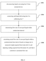
- the controlling means is configured such that the liquid delivering line 9 is disconnected in a conveyance direction downstream of the liquid flowmeter 20 from the external device, and, at the same time, said liquid delivering line 9 is connected in the conveyance direction downstream of said liquid flowmeter 20 to the calibrating line 7 connected to said first tank 12, so that the liquid from the liquid storage tank 14 is pumped by the pump 24 through the flowmeter 20 via the valve 32 to the first tank 12.
- the valve 36 is closed in order to block the liquid from the first tank 12 from flowing to the liquid storage tank 14. Then the controlling means 10 starts storing the weight and time data of the first tank 12 and the liquid contained therein together with the pulse signal data from the flowmeter 20 in relation to time, which is continuously increased, because the liquid is pumped back through the calibrating line 7, and stops storing the weight and time data when the calibration is completed.
- the flow rate of the conveyed liquid within a certain time interval is determined by using change in the liquid weight measured by said weighing sensor 22 in said time interval, wherein the liquid from said liquid storage tank 14 is delivered through the liquid delivering line back to said first tank 12, and the flow rate of the liquid flowed from the liquid storage tank 14 to said first tank 12 is controlled to be a substantially constant value, for example, by an inverter (not shown), such that its condition is close to the actual-operating condition as much as possible.
- Fig. 2 illustrates a second embodiment of an apparatus for a calibration process for the liquid flowmeter of a method according to this invention
- the configuration is similar to that of the embodiment as shown in Fig. 1 , except that load cells 22 is installed in order to weigh a liquid storage tank 14 served as a reservoir bin, wherein the weight is included the weight of the liquid contained in the liquid storage tank 14.
- the second embodiment is suited for the calibration of the flowmeter 20 by measuring the reduction of the weight of the liquid contained in the liquid storage tank 14.
- a pump 39 may be used for pumping the liquid from a first tank 12 back to the liquid storage tank 14 or may let the liquid flowed back through a valve 36 by the gravitational force.
- the load cells 22 is installed underneath the liquid storage tank 14 for reading the loss weight during performing the calibration.
- a controlling means 10 starts storing the weight data of the liquid storage tank 14 and the liquid contained therein, which is continuously decreased, because the liquid contained in the liquid storage tank 14 is pump out, together with the pulse signal data from the flowmeter 20 in relation to time, and stops storing the weight data acquired from the load cells, when the calibration is completed, so that it is used for determining the change in the weight during the calibration.
- the second embodiment further consists of a pump 39 installed interposedly in a flowing line between the first tank 12 and the liquid storage tank 14 for filling the liquid into the liquid storage tank 14 up to a predetermined weight rapidly before starting the calibration.
- a pump 39 installed interposedly in a flowing line between the first tank 12 and the liquid storage tank 14 for filling the liquid into the liquid storage tank 14 up to a predetermined weight rapidly before starting the calibration.
- the controlling means will open the valve 34 and close the valve 32 in order to be able to further perform according to the manufacturing process.
- Fig. 3 is a block diagram of a control system for controlling the liquid flow rate to be constant by a feedback control method.
- an inverter 11 is a device for driving a motor/pump 24 in order to control flow rate of the pump 24 by varying motor input frequency of the motor and pump 24 in the process to be a predetermined setpoint (pulse/minute or pulse/second) at all time such that the flow rate of the liquid at a calibration point is equal to that at an endpoint, which is connected to the external device. If the endpoint is located far and below the calibration point, the inverter will decrease the flow rate of the pump 24, such that the liquid flowed out of the calibration point is decreased. But if the endpoint is located far and above the calibration point, the inverter will increase the flow rate of the pump 24, such that the liquid flowed out of the calibration point is increased.
- the pulse signal acquired from the flow-measuring sensor (flowmeter) 20 in the process is converted to the flow rate in a unit of pulse/minute (or pulse/second depending on the flowmeter specification), wherein one pulse is directly proportional to the instantaneous speed and volume of the liquid flowed through the flow-measuring sensor.
- the pulse/minute (or pulse/second) signal is sent as a feedback signal to the controller 10 in order to instruct the inverter to increase or decrease the output value of the inverter which is a rotational speed control instruction of the electric motor/pump 24, so that the liquid flowed through the pump 24 from the liquid storage tank 14 to the first tank 12 during the calibration is controlled to be a substantially constant flow rate. As explained above, it results that the measurement error is significantly reduced.
- the controller determines an actual flow rate of the conveyed liquid within a certain time interval, namely, from a calibration starting point to a given point (target setpoint), in order to stop performing the calibration, wherein the data are stored intermittently as given in the memory of the controller 10 (step S506), and in step S508, the controller calculates the actual flow rate of the conveyed liquid within this certain time interval from the change rate in the measured weight acquired from the load cells 22, and the reading from the flowmeter 20 is adjusted, such that it conforms to the calculated actual flow rate as will be further explained in detail later.
- the flow rate is controlled by the controller 10 via the operation of the inverter 11 for operating of the pump 24 to be in a range of 50-90% of the operational efficiency of the pump 24, and the flow rate data are stored in the memory, wherein the flow rate is stored in the unit of pulse per second or hertz.
- the controller 10 controls the valve 32 to be opened for filling the liquid back for using in the calibration.
- the speed of the liquid flowed in the pipe may not equal to that at the endpoint.
- the inverter 11 controls the flow rate of the liquid flowed through the pump to be equal to the flow rate at the endpoint using the feedback control with the signal from the flowmeter, wherein the signal may be an analog signal (4-20 mA, 0-10 Vac), or a signal obtained from a pulse train output, or a signal obtained from a serial bus communication system, such as RS232, RS485, and CAN Bus, or the like, such that the flow rate of the liquid flowed through the pump is equal to that at the endpoint during the actual operation.
- Table 1 shows an example of results of a weighing test, Weighing Point Height (m) Pulse Rate (Hz)(1) Inverter Output (%)(2) Measured Weight (kg)(3) Actual Weight (kg)(4) Note 1 (+1) 100 80 25.00 22.50 The calibration point is located near the flowmeter. 2 (+20) 83 80 25.00 25.00 The actual point-of-use has the height and length of the pipe as the factors. 3 (-10) 110 80 25.00 21.30 The actual point-of-use has the height less than that of the flowmeter. 1 (+1) 83 74 25.00 25.00 The inverter is adjusted according to learning use obtained from the machine learning. 2 (+20) 83 80 25.00 25.00 The machine learns from the actual flow rate.
- the inverter is adjusted according to learning use obtained from the machine learning. 2 (+20) 83 85 25.00 25.00 The inverter increases the rotational speed of the motor in the case of the reduced flow rate. wherein (1) the count rate acquired from the flowmeter 20 (pulse/second or hertz), (2) the duty cycle outputs of the inverter 11 calculated in %, (3) the weight shown on the controller (kg), (4) the actual measured weight obtained by weighing the liquid using the external scale, and (5) the machine learns from calculating an average of the actual operation in the last 1-10 times (calculates the average) in order to be set as the setpoint for using in adjusting the flow rate of the liquid flowed through the pump to be constant.
- the single-point calibration is a calibration using only single pulse value as a given setpoint.
- the pulse target is set to be 400 pulses, and then the actual weight is weighed to be 50 kg, and the calibration is stopped when the measured pulses acquired from the flowmeter is equal to the pulse target, wherein the flow rate is controlled to be constant throughout the calibration, and the flow rate of the liquid flowed through the flowmeter 20 is adjusted to be equal to the flow rate during the actual operation.
- Y measured weight acquired from load cells
- X number of counted pulses acquired from flowmeter
- m parameter value
- the measured data are used for calculating m used in setting values in the controller in order to be used in a further process.
- An advantage of the single-point calibration is that it can be done in a short time.
- the multi-point calibration is a calibration using multiple pulse values as the target setpoints.
- Table 2 is an example of data obtained from the 3-point calibration for the flowmeter.
- this invention relates to the calibration method for various flowmeters, such as a displacement flowmeter.
- the calibration method must be performed by testing, wherein a liquid is flowed through an actual flowmeter, and then the weight of the liquid flowed out of the flowmeter is weighed in order to calculate values of parameters used in a control system, which can be divided into two main sections, namely, (1) a signal receiving and processing unit comprising a readymade meter and an embedded chip programmable logic control unit, and (2) a human-machine interface.
- the readymade meter may have press-buttons or accessory displays for users, such as a readymade screen with controlling via control buttons, a readymade screen with controlling via a touch screen or a computer having an auxiliary program.
- the liquid weighing process can be easily performed, and at the same time, the novel calibration method can rapidly calculate the parameter values, has no waste of the liquid subjected to the calibration, and has no time loss relating to the time for refilling the tested liquid back into the tank.
- the calibration can be performed in the region located near the flowmeter installation position using the inverter for properly controlling the liquid flow rate, and at the same time, the weighing system can be installed on the upper side of the device itself (the first form), or can use the loss-in-weight principle (the second form) having the valve control system for controlling the flow of the liquid back to be weighed at the upper part.
- the single-point and multi-point calibration can easily be performed, wherein it can be performed in the region within 5 m from the flowmeter, even though the actual point-of-use is much farther apart thereform.
- the apparatus can perform both of the manual flowmeter calibration, wherein the flow rate is adjusted by the operator of the inverter, and automatic flowmeter calibration, wherein the machine learning obtained from the actual operation is used for the automatic control of the inverter using retro-statistical data obtained from the actual operation of the motor and pump as the setpoint of the inverter.
- the liquid subjected to the calibration can be reused immediately without discarding the liquid waste or refilled to the tank by pumping or forcing down, whereas in the prior art, the weighed liquid must be discarded or must be refilled to the tank later. Therefore, coming in contact with the liquid, which can be hazardous substance, can be reduced, it can promote the safety to workers.
Landscapes
- Physics & Mathematics (AREA)
- Fluid Mechanics (AREA)
- General Physics & Mathematics (AREA)
- Measuring Volume Flow (AREA)
- Loading And Unloading Of Fuel Tanks Or Ships (AREA)
Claims (5)
- Procédé d'étalonnage pour débitmètre de liquide comprenant les étapes de:prévoir un premier réservoir (12) pour recevoir ledit liquide à mesurer et un réservoir de stockage de liquide (14) relié audit premier réservoir (12);prévoir une conduite de distribution de liquide (9) pour transporter le liquide dudit réservoir de stockage de liquide (14) à un dispositif externe;prévoir un capteur de pesée (22) pour peser le liquide contenu dans le premier réservoir (12) ou le réservoir de stockage de liquide (14),pendant la réalisation de l'étalonnage pour le débitmètre (20):déconnecter la conduite de distribution de liquide (9) dans une direction de transport en aval du débitmètre de liquide (20) du dispositif externe;connecter ladite conduite de distribution de liquide (9) dans la direction de transport en aval dudit débitmètre de liquide (20) à une conduite d'étalonnage (7) connectée audit premier réservoir (12) de sorte que le liquide provenant dudit réservoir de stockage de liquide (14) est distribué par la conduite de distribution de liquide (9) de manière à traverser le débitmètre (20) pour revenir audit premier réservoir (12); etdéterminer un débit estimé du liquide transporté en calculant la variation de poids du liquide transporté mesurée par ledit capteur de pesée (22) pendant un intervalle de temps prédéterminé,le procédé étant caractérisé en ce que, pendant la réalisation de l'étalonnage, le débit du liquide dudit réservoir de stockage de liquide (14) audit premier réservoir (12) à travers le débitmètre (20) est commandé par un dispositif de commande (10) de manière à être sensiblement constant et sensiblement égal au débit pendant le fonctionnement réel, pendant tout l'étalonnage, en utilisant un signal de rétroaction provenant du débitmètre (20) et en ce que la lecture provenant du débitmètre est ajustée de manière à être en conformité avec ledit débit estimé.
- Procédé selon la revendication 1, dans lequel, pendant l'étalonnage pour le débitmètre, la déconnexion de la conduite de distribution de liquide (9) du dispositif externe et la connexion de ladite conduite de distribution de liquide (9) à ladite conduite d'étalonnage (7) sont réalisées par deux vannes à 2 voies (32, 34) ou une vanne à 3 voies qui est commandée manuellement, ou électriquement, ou pneumatiquement.
- Procédé selon l'une quelconque des revendications précédentes, dans lequel ledit procédé d'étalonnage est un étalonnage à un seul point ou un étalonnage à plusieurs points.
- Procédé selon l'une quelconque des revendications précédentes, dans lequel le liquide s'écoule du premier réservoir (12) au réservoir de stockage de liquide (14) par apport par gravité ou une force d'entraînement provenant d'une pompe (39) installée de manière interposée dans une conduite d'écoulement entre le premier réservoir (12) et le réservoir de stockage de liquide (14).
- Procédé selon l'une quelconque des revendications précédentes, où un point de consigne utilisé pour commander ledit débit de liquide pour qu'il soit sensiblement constant est calculé d'après une moyenne des débits en fonctionnement réel dans une période de temps spécifique avant la réalisation de l'étalonnage.
Applications Claiming Priority (2)
| Application Number | Priority Date | Filing Date | Title |
|---|---|---|---|
| TH1903000869 | 2019-04-10 | ||
| PCT/TH2020/000007 WO2020209806A1 (fr) | 2019-04-10 | 2020-02-04 | Procédé d'étalonnage pour débitmètre de liquide |
Publications (4)
| Publication Number | Publication Date |
|---|---|
| EP3953668A1 EP3953668A1 (fr) | 2022-02-16 |
| EP3953668A4 EP3953668A4 (fr) | 2022-12-28 |
| EP3953668C0 EP3953668C0 (fr) | 2025-03-26 |
| EP3953668B1 true EP3953668B1 (fr) | 2025-03-26 |
Family
ID=72751140
Family Applications (1)
| Application Number | Title | Priority Date | Filing Date |
|---|---|---|---|
| EP20788297.8A Active EP3953668B1 (fr) | 2019-04-10 | 2020-02-04 | Procédé d'étalonnage pour débitmètre de liquide |
Country Status (11)
| Country | Link |
|---|---|
| US (1) | US11768099B2 (fr) |
| EP (1) | EP3953668B1 (fr) |
| JP (1) | JP7429699B2 (fr) |
| KR (1) | KR102891382B1 (fr) |
| CN (1) | CN113167632B (fr) |
| AU (1) | AU2020272448A1 (fr) |
| BR (1) | BR112021009526A2 (fr) |
| MY (1) | MY208526A (fr) |
| PH (1) | PH12021550960A1 (fr) |
| SG (1) | SG11202104328VA (fr) |
| WO (1) | WO2020209806A1 (fr) |
Families Citing this family (17)
| Publication number | Priority date | Publication date | Assignee | Title |
|---|---|---|---|---|
| CN112393772B (zh) * | 2020-11-20 | 2022-09-16 | 江苏省计量科学研究院 | 胰岛素泵计量校准装置 |
| US11566968B2 (en) * | 2021-01-19 | 2023-01-31 | Rolls-Royce Corporation | Control of particle delivery in contamination test rig |
| CN112841701A (zh) * | 2021-03-12 | 2021-05-28 | 河南中烟工业有限责任公司 | 一种制丝叶片加料系统及其流量精度监测方法 |
| CN113588047B (zh) * | 2021-08-04 | 2022-05-10 | 西安航天动力试验技术研究所 | 低温推进剂火箭发动机的流量计标定系统及方法 |
| JP7740823B2 (ja) * | 2021-09-16 | 2025-09-17 | 東京エレクトロン株式会社 | 流量計校正システム、基板処理装置および流量計校正方法 |
| CN113758546B (zh) * | 2021-09-23 | 2024-06-28 | 深圳市质量安全检验检测研究院 | 流量计的校准装置及其校准方法、以及待测流量计组件 |
| CN114061708A (zh) * | 2021-11-01 | 2022-02-18 | 湖州市检验检测中心 | 一种高精度自动控制液体流量计(仪)在线校准装置 |
| CN114088169B (zh) * | 2021-11-09 | 2023-08-04 | 浙江浙能富兴燃料有限公司 | 一种气压驱动的双向质量法液氢流量标准装置 |
| CN114392682B (zh) * | 2021-12-02 | 2023-01-13 | 崴思新材料泰州有限公司 | 一种全自动胶水配制混合系统 |
| CN114441209B (zh) * | 2022-01-28 | 2024-05-17 | 瑞幸咖啡科技(海南)有限公司 | 一种液体输出设备的校准方法、装置、设备和介质 |
| CN115217750B (zh) * | 2022-06-06 | 2024-03-29 | 河南省计量测试科学研究院 | 液相色谱仪中输液泵的校准装置 |
| CN115531661B (zh) * | 2022-10-28 | 2023-07-18 | 巨翊医疗科技(苏州)有限公司 | 一种抗干扰静脉输液流速测量方法、装置及系统 |
| CN115856357A (zh) * | 2022-11-18 | 2023-03-28 | 陕西省计量科学研究院 | 基于恒定均匀流的流速仪校准方法及其装置 |
| KR102647589B1 (ko) * | 2023-08-22 | 2024-03-14 | 한국수력원자력 주식회사 | 원전 주급수 벤튜리 유량계 정비시스템 |
| KR102934897B1 (ko) * | 2023-10-13 | 2026-03-06 | 한국표준과학연구원 | 액체유량계 극저온 교정 시스템 및 이의 운전 방법 |
| CN117109709B (zh) * | 2023-10-20 | 2024-06-28 | 青岛鼎信通讯科技有限公司 | 一种超声水表校准方法 |
| CN118980416B (zh) * | 2024-07-23 | 2025-02-25 | 苏州国方计量集团有限公司 | 一种基于电参数采集分析的液体流量计校准系统 |
Family Cites Families (28)
| Publication number | Priority date | Publication date | Assignee | Title |
|---|---|---|---|---|
| JPH0612285B2 (ja) * | 1987-12-25 | 1994-02-16 | 科学技術庁航空宇宙技術研究所長 | 流量計の較正装置 |
| US4965756A (en) * | 1988-10-11 | 1990-10-23 | Gas Research Institute | Method and apparatus for calibration of electronic gas meters |
| JP2003303023A (ja) * | 2002-02-07 | 2003-10-24 | Tokyo Electron Ltd | 処理装置及び処理装置の保守方法 |
| RO119748B1 (ro) * | 2002-11-29 | 2005-02-28 | Cezar Gordân | Metodă şi instalaţie masică pentru verificarea şi etalonarea apometrelor |
| JP2007046921A (ja) | 2005-08-08 | 2007-02-22 | Hirai:Kk | 気体供給装置 |
| RO123231B1 (ro) * | 2006-06-28 | 2011-03-30 | Ioan Alecu | Instalaţie gravimetrică pentru verificarea contoarelor de apă |
| DE102007043907A1 (de) | 2007-09-14 | 2009-03-26 | Siemens Ag | Kalibrierung von Staubmassenstrommess-Systemen |
| US20150355003A1 (en) * | 2013-01-11 | 2015-12-10 | Feedlogic Corporation | Accelerometer-based system for monitoring flow |
| JP6264152B2 (ja) * | 2014-03-31 | 2018-01-24 | 日立金属株式会社 | 質量流量計、及び当該質量流量計を使用する質量流量制御装置 |
| CN104375520B (zh) * | 2014-11-05 | 2017-10-27 | 北京航天计量测试技术研究所 | 一种自动稳定水流量的装置及方法 |
| US20160302352A1 (en) | 2015-04-16 | 2016-10-20 | Daniel Tramp | High redundancy seed coating apparatus and method |
| CN204730917U (zh) * | 2015-06-24 | 2015-10-28 | 广东康宝莱智慧水务有限公司 | 双重流量标定称重系统 |
| JP6557550B2 (ja) * | 2015-08-21 | 2019-08-07 | アズビル株式会社 | 液体用流量計の試験方法、および試験装置 |
| ITUB20154014A1 (it) * | 2015-09-29 | 2017-03-29 | Certech Spa Con Socio Unico | Dispositivo compensatore per pompe volumetriche. |
| CN105509844B (zh) * | 2015-11-23 | 2018-09-28 | 华南理工大学 | 一种通用液体流量校准装置开式换向器检定方法 |
| US10126761B2 (en) * | 2015-12-29 | 2018-11-13 | Hitachi Metals, Ltd. | Gas insensitive mass flow control systems and methods |
| JP6649646B2 (ja) * | 2016-04-05 | 2020-02-19 | 国立研究開発法人産業技術総合研究所 | 液体用流量計校正装置 |
| CN106197623A (zh) * | 2016-09-05 | 2016-12-07 | 安徽理工大学 | 一种基于称重法的容积式高压流量计标定液压系统及实验方法 |
| KR101942014B1 (ko) * | 2016-11-21 | 2019-01-24 | 한국표준과학연구원 | 유량계 평가 시스템 및 평가 방법 |
| CN206440357U (zh) * | 2016-12-28 | 2017-08-25 | 新乡航空工业(集团)有限公司 | 15号航空液压油微小流量标准装置 |
| CN107131931B (zh) * | 2017-06-06 | 2020-02-21 | 西安航天动力试验技术研究所 | 姿控发动机高温推进剂稳态流量原位校准装置及校准方法 |
| KR102055055B1 (ko) * | 2017-06-26 | 2019-12-11 | 김영탁 | 전자식 유량계 및 그 측정 오차 보정방법 |
| CN206945098U (zh) | 2017-06-28 | 2018-01-30 | 福建南方路面机械有限公司 | 一种科氏质量流量计校准系统 |
| CN207317905U (zh) * | 2017-10-30 | 2018-05-04 | 西门子传感器与通讯有限公司 | 流量计校准装置 |
| KR101961269B1 (ko) * | 2017-11-02 | 2019-03-22 | 한국산업기술시험원 | 유량계 교정용 유동전환밸브를 이용한 유량계 교정 시스템 |
| CN108195447B (zh) * | 2018-02-13 | 2020-03-24 | 无锡市计量测试院 | 流量计校准系统和校准方法 |
| CN108981970B (zh) * | 2018-04-08 | 2020-01-07 | 北京市热力集团有限责任公司 | 计量装置自动标定系统 |
| CN208383250U (zh) * | 2018-07-30 | 2019-01-15 | 锦州天辰博锐仪表有限公司 | 小流量质量流量计标定装置 |
-
2020
- 2020-02-04 WO PCT/TH2020/000007 patent/WO2020209806A1/fr not_active Ceased
- 2020-02-04 AU AU2020272448A patent/AU2020272448A1/en not_active Abandoned
- 2020-02-04 MY MYPI2021002764A patent/MY208526A/en unknown
- 2020-02-04 KR KR1020217015197A patent/KR102891382B1/ko active Active
- 2020-02-04 EP EP20788297.8A patent/EP3953668B1/fr active Active
- 2020-02-04 CN CN202080006361.0A patent/CN113167632B/zh active Active
- 2020-02-04 BR BR112021009526-8A patent/BR112021009526A2/pt not_active Application Discontinuation
- 2020-02-04 US US17/433,925 patent/US11768099B2/en active Active
- 2020-02-04 SG SG11202104328VA patent/SG11202104328VA/en unknown
- 2020-02-04 JP JP2021538405A patent/JP7429699B2/ja active Active
-
2021
- 2021-04-28 PH PH12021550960A patent/PH12021550960A1/en unknown
Also Published As
| Publication number | Publication date |
|---|---|
| JP7429699B2 (ja) | 2024-02-08 |
| KR102891382B1 (ko) | 2025-11-25 |
| US20220049987A1 (en) | 2022-02-17 |
| EP3953668C0 (fr) | 2025-03-26 |
| EP3953668A1 (fr) | 2022-02-16 |
| EP3953668A4 (fr) | 2022-12-28 |
| WO2020209806A1 (fr) | 2020-10-15 |
| SG11202104328VA (en) | 2021-05-28 |
| KR20210149022A (ko) | 2021-12-08 |
| CN113167632B (zh) | 2025-06-13 |
| MY208526A (en) | 2025-05-14 |
| BR112021009526A2 (pt) | 2021-10-26 |
| JP2022528029A (ja) | 2022-06-08 |
| US11768099B2 (en) | 2023-09-26 |
| PH12021550960A1 (en) | 2021-11-29 |
| AU2020272448A1 (en) | 2021-05-27 |
| CN113167632A (zh) | 2021-07-23 |
Similar Documents
| Publication | Publication Date | Title |
|---|---|---|
| EP3953668B1 (fr) | Procédé d'étalonnage pour débitmètre de liquide | |
| EP0930996B1 (fr) | Systeme de distributeur melangeur sensible a l'indice d'octane | |
| CN102389742B (zh) | 一种高精度配料设备及其控制方法 | |
| CA2469267C (fr) | Methode et dispositif de dosage gravimetrique de matieres en vrac | |
| CN207452206U (zh) | 一种烧结配料的配料流量调节系统 | |
| CN105741426A (zh) | 一种液体售卖机的计量系统及控制方法 | |
| CN209802466U (zh) | 一种计量装置 | |
| CN214076555U (zh) | 一种高精密自动投料反应装置 | |
| CN207007301U (zh) | 一种自动校验的配料称量装置 | |
| CN105844800A (zh) | 液体售卖机的出液计量系统及其计量方法 | |
| CA3106173A1 (fr) | Systeme d'entree pour moulin a cylindres, moulin a cylindres equipe d'un tel systeme d'entree et procede pour la determination du niveau de remplissage de produit a broyer d'un re servoir d'un moulin a cylindres | |
| CN209917799U (zh) | 一种多功能型多液体添加系统 | |
| CN109464959A (zh) | 一种进一步提高化工浆料连续性生产投料配比精度的投料系统和方法 | |
| CN209727227U (zh) | 一种计量装置 | |
| CN214094021U (zh) | 一种液体物料自动定量送料控制装置 | |
| JP2003294519A (ja) | 連続粉体供給装置における供給量計測方法 | |
| CN207287340U (zh) | 一种进一步提高化工浆料连续性生产投料配比精度的投料系统 | |
| CN205644786U (zh) | 液体售卖机的出液计量系统 | |
| JP2011051624A (ja) | 液体の定量充填方法および装置 | |
| CN111730777B (zh) | 一种称重式液体色母机及其自动校正方法和应用 | |
| JPH02191193A (ja) | 定量充填制御される充填方法とその装置 | |
| EP4096889A1 (fr) | Système de dosage de liquide associé à la régulation de masse de la quantité dosée et traitement de dosage associé | |
| CN207174772U (zh) | 一种球磨机恒定给矿控制装置 | |
| CN204841442U (zh) | 一种带计量的搅拌器 | |
| CN209490700U (zh) | 一种工业固体废渣补水系统 |
Legal Events
| Date | Code | Title | Description |
|---|---|---|---|
| STAA | Information on the status of an ep patent application or granted ep patent |
Free format text: STATUS: THE INTERNATIONAL PUBLICATION HAS BEEN MADE |
|
| PUAI | Public reference made under article 153(3) epc to a published international application that has entered the european phase |
Free format text: ORIGINAL CODE: 0009012 |
|
| STAA | Information on the status of an ep patent application or granted ep patent |
Free format text: STATUS: REQUEST FOR EXAMINATION WAS MADE |
|
| 17P | Request for examination filed |
Effective date: 20210602 |
|
| AK | Designated contracting states |
Kind code of ref document: A1 Designated state(s): AL AT BE BG CH CY CZ DE DK EE ES FI FR GB GR HR HU IE IS IT LI LT LU LV MC MK MT NL NO PL PT RO RS SE SI SK SM TR |
|
| DAV | Request for validation of the european patent (deleted) | ||
| DAX | Request for extension of the european patent (deleted) | ||
| A4 | Supplementary search report drawn up and despatched |
Effective date: 20221129 |
|
| RIC1 | Information provided on ipc code assigned before grant |
Ipc: G01F 25/10 20220101AFI20221123BHEP |
|
| REG | Reference to a national code |
Ref country code: DE Ref legal event code: R079 Free format text: PREVIOUS MAIN CLASS: G01F0025000000 Ipc: G01F0025100000 Ref country code: DE Ref legal event code: R079 Ref document number: 602020048368 Country of ref document: DE Free format text: PREVIOUS MAIN CLASS: G01F0025000000 Ipc: G01F0025100000 |
|
| GRAP | Despatch of communication of intention to grant a patent |
Free format text: ORIGINAL CODE: EPIDOSNIGR1 |
|
| STAA | Information on the status of an ep patent application or granted ep patent |
Free format text: STATUS: GRANT OF PATENT IS INTENDED |
|
| RIC1 | Information provided on ipc code assigned before grant |
Ipc: G01F 25/10 20220101AFI20241031BHEP |
|
| INTG | Intention to grant announced |
Effective date: 20241120 |
|
| GRAS | Grant fee paid |
Free format text: ORIGINAL CODE: EPIDOSNIGR3 |
|
| GRAA | (expected) grant |
Free format text: ORIGINAL CODE: 0009210 |
|
| STAA | Information on the status of an ep patent application or granted ep patent |
Free format text: STATUS: THE PATENT HAS BEEN GRANTED |
|
| AK | Designated contracting states |
Kind code of ref document: B1 Designated state(s): AL AT BE BG CH CY CZ DE DK EE ES FI FR GB GR HR HU IE IS IT LI LT LU LV MC MK MT NL NO PL PT RO RS SE SI SK SM TR |
|
| REG | Reference to a national code |
Ref country code: GB Ref legal event code: FG4D |
|
| REG | Reference to a national code |
Ref country code: CH Ref legal event code: EP |
|
| REG | Reference to a national code |
Ref country code: DE Ref legal event code: R096 Ref document number: 602020048368 Country of ref document: DE |
|
| REG | Reference to a national code |
Ref country code: IE Ref legal event code: FG4D |
|
| U01 | Request for unitary effect filed |
Effective date: 20250326 |
|
| U07 | Unitary effect registered |
Designated state(s): AT BE BG DE DK EE FI FR IT LT LU LV MT NL PT RO SE SI Effective date: 20250402 |
|
| PG25 | Lapsed in a contracting state [announced via postgrant information from national office to epo] |
Ref country code: RS Free format text: LAPSE BECAUSE OF FAILURE TO SUBMIT A TRANSLATION OF THE DESCRIPTION OR TO PAY THE FEE WITHIN THE PRESCRIBED TIME-LIMIT Effective date: 20250626 |
|
| PG25 | Lapsed in a contracting state [announced via postgrant information from national office to epo] |
Ref country code: NO Free format text: LAPSE BECAUSE OF FAILURE TO SUBMIT A TRANSLATION OF THE DESCRIPTION OR TO PAY THE FEE WITHIN THE PRESCRIBED TIME-LIMIT Effective date: 20250626 |
|
| PG25 | Lapsed in a contracting state [announced via postgrant information from national office to epo] |
Ref country code: HR Free format text: LAPSE BECAUSE OF FAILURE TO SUBMIT A TRANSLATION OF THE DESCRIPTION OR TO PAY THE FEE WITHIN THE PRESCRIBED TIME-LIMIT Effective date: 20250326 |
|
| PG25 | Lapsed in a contracting state [announced via postgrant information from national office to epo] |
Ref country code: GR Free format text: LAPSE BECAUSE OF FAILURE TO SUBMIT A TRANSLATION OF THE DESCRIPTION OR TO PAY THE FEE WITHIN THE PRESCRIBED TIME-LIMIT Effective date: 20250627 |
|
| PG25 | Lapsed in a contracting state [announced via postgrant information from national office to epo] |
Ref country code: SM Free format text: LAPSE BECAUSE OF FAILURE TO SUBMIT A TRANSLATION OF THE DESCRIPTION OR TO PAY THE FEE WITHIN THE PRESCRIBED TIME-LIMIT Effective date: 20250326 |
|
| PG25 | Lapsed in a contracting state [announced via postgrant information from national office to epo] |
Ref country code: ES Free format text: LAPSE BECAUSE OF FAILURE TO SUBMIT A TRANSLATION OF THE DESCRIPTION OR TO PAY THE FEE WITHIN THE PRESCRIBED TIME-LIMIT Effective date: 20250326 |
|
| PG25 | Lapsed in a contracting state [announced via postgrant information from national office to epo] |
Ref country code: PL Free format text: LAPSE BECAUSE OF FAILURE TO SUBMIT A TRANSLATION OF THE DESCRIPTION OR TO PAY THE FEE WITHIN THE PRESCRIBED TIME-LIMIT Effective date: 20250326 |
|
| PG25 | Lapsed in a contracting state [announced via postgrant information from national office to epo] |
Ref country code: SK Free format text: LAPSE BECAUSE OF FAILURE TO SUBMIT A TRANSLATION OF THE DESCRIPTION OR TO PAY THE FEE WITHIN THE PRESCRIBED TIME-LIMIT Effective date: 20250326 |
|
| PG25 | Lapsed in a contracting state [announced via postgrant information from national office to epo] |
Ref country code: IS Free format text: LAPSE BECAUSE OF FAILURE TO SUBMIT A TRANSLATION OF THE DESCRIPTION OR TO PAY THE FEE WITHIN THE PRESCRIBED TIME-LIMIT Effective date: 20250726 |
|
| PG25 | Lapsed in a contracting state [announced via postgrant information from national office to epo] |
Ref country code: CZ Free format text: LAPSE BECAUSE OF FAILURE TO SUBMIT A TRANSLATION OF THE DESCRIPTION OR TO PAY THE FEE WITHIN THE PRESCRIBED TIME-LIMIT Effective date: 20250326 |
|
| PLBE | No opposition filed within time limit |
Free format text: ORIGINAL CODE: 0009261 |
|
| STAA | Information on the status of an ep patent application or granted ep patent |
Free format text: STATUS: NO OPPOSITION FILED WITHIN TIME LIMIT |
|
| REG | Reference to a national code |
Ref country code: CH Ref legal event code: L10 Free format text: ST27 STATUS EVENT CODE: U-0-0-L10-L00 (AS PROVIDED BY THE NATIONAL OFFICE) Effective date: 20260211 |
|
| 26N | No opposition filed |
Effective date: 20260105 |
|
| U20 | Renewal fee for the european patent with unitary effect paid |
Year of fee payment: 7 Effective date: 20260213 |
|
| PGFP | Annual fee paid to national office [announced via postgrant information from national office to epo] |
Ref country code: GB Payment date: 20260213 Year of fee payment: 7 |