EP3954890A1 - Démarreur pour un moteur à combustion interne et son procédé de fabrication - Google Patents
Démarreur pour un moteur à combustion interne et son procédé de fabrication Download PDFInfo
- Publication number
- EP3954890A1 EP3954890A1 EP21178755.1A EP21178755A EP3954890A1 EP 3954890 A1 EP3954890 A1 EP 3954890A1 EP 21178755 A EP21178755 A EP 21178755A EP 3954890 A1 EP3954890 A1 EP 3954890A1
- Authority
- EP
- European Patent Office
- Prior art keywords
- starter
- component
- relay
- housing
- relay housing
- Prior art date
- Legal status (The legal status is an assumption and is not a legal conclusion. Google has not performed a legal analysis and makes no representation as to the accuracy of the status listed.)
- Withdrawn
Links
- 239000007858 starting material Substances 0.000 title claims abstract description 58
- 238000002485 combustion reaction Methods 0.000 title claims abstract description 10
- 238000004519 manufacturing process Methods 0.000 title claims abstract description 8
- 238000000034 method Methods 0.000 title claims abstract description 4
- 239000000463 material Substances 0.000 claims description 10
- 229910000831 Steel Inorganic materials 0.000 claims description 4
- XAGFODPZIPBFFR-UHFFFAOYSA-N aluminium Chemical compound [Al] XAGFODPZIPBFFR-UHFFFAOYSA-N 0.000 claims description 4
- 229910052782 aluminium Inorganic materials 0.000 claims description 4
- 239000010959 steel Substances 0.000 claims description 4
- XLYOFNOQVPJJNP-UHFFFAOYSA-N water Substances O XLYOFNOQVPJJNP-UHFFFAOYSA-N 0.000 description 4
- 238000007789 sealing Methods 0.000 description 3
- 238000009826 distribution Methods 0.000 description 2
- 239000003566 sealing material Substances 0.000 description 2
- 230000001419 dependent effect Effects 0.000 description 1
- 238000004049 embossing Methods 0.000 description 1
- 230000004907 flux Effects 0.000 description 1
- 230000000149 penetrating effect Effects 0.000 description 1
- 229920001296 polysiloxane Polymers 0.000 description 1
Images

Classifications
-
- F—MECHANICAL ENGINEERING; LIGHTING; HEATING; WEAPONS; BLASTING
- F02—COMBUSTION ENGINES; HOT-GAS OR COMBUSTION-PRODUCT ENGINE PLANTS
- F02N—STARTING OF COMBUSTION ENGINES; STARTING AIDS FOR SUCH ENGINES, NOT OTHERWISE PROVIDED FOR
- F02N15/00—Other power-operated starting apparatus; Component parts, details, or accessories, not provided for in, or of interest apart from groups F02N5/00 - F02N13/00
- F02N15/02—Gearing between starting-engines and started engines; Engagement or disengagement thereof
- F02N15/04—Gearing between starting-engines and started engines; Engagement or disengagement thereof the gearing including disengaging toothed gears
- F02N15/06—Gearing between starting-engines and started engines; Engagement or disengagement thereof the gearing including disengaging toothed gears the toothed gears being moved by axial displacement
- F02N15/067—Gearing between starting-engines and started engines; Engagement or disengagement thereof the gearing including disengaging toothed gears the toothed gears being moved by axial displacement the starter comprising an electro-magnetically actuated lever
-
- F—MECHANICAL ENGINEERING; LIGHTING; HEATING; WEAPONS; BLASTING
- F02—COMBUSTION ENGINES; HOT-GAS OR COMBUSTION-PRODUCT ENGINE PLANTS
- F02N—STARTING OF COMBUSTION ENGINES; STARTING AIDS FOR SUCH ENGINES, NOT OTHERWISE PROVIDED FOR
- F02N11/00—Starting of engines by means of electric motors
- F02N11/08—Circuits specially adapted for starting of engines
-
- F—MECHANICAL ENGINEERING; LIGHTING; HEATING; WEAPONS; BLASTING
- F02—COMBUSTION ENGINES; HOT-GAS OR COMBUSTION-PRODUCT ENGINE PLANTS
- F02N—STARTING OF COMBUSTION ENGINES; STARTING AIDS FOR SUCH ENGINES, NOT OTHERWISE PROVIDED FOR
- F02N11/00—Starting of engines by means of electric motors
-
- F—MECHANICAL ENGINEERING; LIGHTING; HEATING; WEAPONS; BLASTING
- F02—COMBUSTION ENGINES; HOT-GAS OR COMBUSTION-PRODUCT ENGINE PLANTS
- F02N—STARTING OF COMBUSTION ENGINES; STARTING AIDS FOR SUCH ENGINES, NOT OTHERWISE PROVIDED FOR
- F02N15/00—Other power-operated starting apparatus; Component parts, details, or accessories, not provided for in, or of interest apart from groups F02N5/00 - F02N13/00
- F02N15/02—Gearing between starting-engines and started engines; Engagement or disengagement thereof
- F02N15/022—Gearing between starting-engines and started engines; Engagement or disengagement thereof the starter comprising an intermediate clutch
- F02N15/023—Gearing between starting-engines and started engines; Engagement or disengagement thereof the starter comprising an intermediate clutch of the overrunning type
-
- F—MECHANICAL ENGINEERING; LIGHTING; HEATING; WEAPONS; BLASTING
- F16—ENGINEERING ELEMENTS AND UNITS; GENERAL MEASURES FOR PRODUCING AND MAINTAINING EFFECTIVE FUNCTIONING OF MACHINES OR INSTALLATIONS; THERMAL INSULATION IN GENERAL
- F16J—PISTONS; CYLINDERS; SEALINGS
- F16J15/00—Sealings
- F16J15/02—Sealings between relatively-stationary surfaces
- F16J15/04—Sealings between relatively-stationary surfaces without packing between the surfaces, e.g. with ground surfaces, with cutting edge
-
- F—MECHANICAL ENGINEERING; LIGHTING; HEATING; WEAPONS; BLASTING
- F02—COMBUSTION ENGINES; HOT-GAS OR COMBUSTION-PRODUCT ENGINE PLANTS
- F02N—STARTING OF COMBUSTION ENGINES; STARTING AIDS FOR SUCH ENGINES, NOT OTHERWISE PROVIDED FOR
- F02N11/00—Starting of engines by means of electric motors
- F02N11/10—Safety devices
-
- F—MECHANICAL ENGINEERING; LIGHTING; HEATING; WEAPONS; BLASTING
- F02—COMBUSTION ENGINES; HOT-GAS OR COMBUSTION-PRODUCT ENGINE PLANTS
- F02N—STARTING OF COMBUSTION ENGINES; STARTING AIDS FOR SUCH ENGINES, NOT OTHERWISE PROVIDED FOR
- F02N15/00—Other power-operated starting apparatus; Component parts, details, or accessories, not provided for in, or of interest apart from groups F02N5/00 - F02N13/00
- F02N15/006—Assembling or mounting of starting devices
-
- F—MECHANICAL ENGINEERING; LIGHTING; HEATING; WEAPONS; BLASTING
- F02—COMBUSTION ENGINES; HOT-GAS OR COMBUSTION-PRODUCT ENGINE PLANTS
- F02N—STARTING OF COMBUSTION ENGINES; STARTING AIDS FOR SUCH ENGINES, NOT OTHERWISE PROVIDED FOR
- F02N2250/00—Problems related to engine starting or engine's starting apparatus
- F02N2250/08—Lubrication of starters; Sealing means for starters
Definitions
- the present invention relates to a starter for an internal combustion engine with a starter relay and a method for producing such a starter.
- Starters are used to start internal combustion engines and typically have a motor or electric motor, which - usually via various components such as planetary gears and overrunning clutches or freewheels - drives a pinion shaft and thus a pinion mounted on it, which is connected to a ring gear of the internal combustion engine is engaged to start it.
- a motor or electric motor which - usually via various components such as planetary gears and overrunning clutches or freewheels - drives a pinion shaft and thus a pinion mounted on it, which is connected to a ring gear of the internal combustion engine is engaged to start it.
- a starter relay also referred to as an engagement relay
- a magnetic switch for example.
- the starter relay is usually part of the starter or can be regarded as part of the starter, but has a separate housing (i.e. a relay housing) which is attached to a motor housing or a housing flange or another component of the starter, for example. One or more screws can be used for this.
- the present invention relates to a starter for an internal combustion engine, as already described above, ie the starter has a starter relay such as a Magnetic switch, and a method for its manufacture.
- a relay housing of the starter relay rests in a contact area on a component of the starter that is different from the relay housing, eg a motor housing or a housing flange, and is screwed to this component by means of one or more screws.
- a lever mechanism for transmitting a movement of the starter relay and on the other hand various components from electric motor to (planetary) gear and freewheel to pinion can be present, but these are not specifically important in the present invention.
- Recesses or bores are provided in the relay housing and in the component for the one or more screws.
- Suitable screws are e.g. countersunk screws, for which through-holes or bores are provided as recesses in the component, for the countersunk head then correspondingly e.g. also conical widenings.
- threaded holes are expedient as recesses, so that the screws simply have to be guided through the recesses in the component and inserted and screwed into the recesses in the relay housing.
- the recesses are each surrounded by the contact area, i.e. the recesses and the contact area - i.e. the areas of the relay housing and component that abut one another - are designed in such a way that the screws - when screwed in - are surrounded by the contact area so that the Clamping force can be transmitted accordingly by the screws.
- the term contact area is to be understood here in particular generically, i.e. there can also be several (separate) contact areas, e.g.
- a contact area in the area of each recess but it is expedient if a contact area extends, for example, approximately annularly around the circumference of an end face of the relay housing , which is typically approximately cylindrical, extends in order to achieve an even distribution of the clamping force through the screws.
- sealing material e.g. silicone
- Another way to do this is, for example, to provide a sealing ring, e.g. made of rubber, in the contact area, i.e. between the relay housing and the component. This, like the possibility of sealing material around the thread, causes additional costs and increased manufacturing effort due to additional work steps when assembling the starter.
- elevations in the relay housing or in the component (i.e. in particular in one of the two components), which surround the one or more recesses and are screwed together by means of the one or the plurality of screws are pressed or are pressed into the relay housing or into the component.
- elevations are in particular each raised relative to a flat surface (e.g. an end face of the relay housing) and can be produced, for example, by stamping and/or embossing, and are therefore in particular formed integrally with the relay housing or in the component. They surround the recesses in the manner of a ridge.
- each of which is surrounded by an elevation, ie particularly in the case of several screws—and a corresponding number of recesses—each of the screws or recesses is surrounded by such an elevation, for example at a distance in the radial direction viewed in relation to an axis of rotation of the one or more screws, of at most one diameter, preferably at most half a diameter, of the recess (in particular that in the component on which the elevation is provided).
- These elevations can have a thickness (or width) in the radial direction in relation to an axis of rotation of the one or more screws of at most half a diameter, preferably at most a quarter of the diameter, of the recesses, and preferably ring-shaped.
- a height of the bumps (above the flat surface) can be kept small, eg half a millimeter. In principle, however, it is also conceivable that if there are several screws or corresponding recesses, only one elevation is provided for this purpose, which then surrounds them all and runs, for example, in a ring shape around the circumference of the end face of the relay housing.
- a material of that component in which the elevations are formed has a higher hardness than a material of that component into which the elevations are pressed.
- Such a material should be provided at least in the contact area, but it can also be expedient if a larger area has this respective material.
- the relay housing In the case of a starter, it makes sense for the relay housing to be made of the material with the higher hardness, especially since a starter relay housing is typically made of steel or at least has steel in order to be able to direct a magnetic flux appropriately (as mentioned, it is a starter relay typically around a magnetic switch).
- the motor housing or a housing flange as the component is usually made of aluminum or die-cast aluminum.
- FIG 1 1 shows starter 100 according to the invention for an internal combustion engine in a preferred embodiment in a schematic sectional view.
- the starter 100 has a starter relay 110, which in turn has a relay housing 112 in or on which an electromagnet 114, a movable armature 115 and two connecting bolts 113 are provided.
- the starter 100 has an electric motor 122, a gear 124, a freewheel 126 and a pinion 128, which are arranged on a shaft 121.
- Pinion 128 and here, for example, also freewheel 126 can be moved by means of a lever mechanism with a lever 130 which is connected to the armature 115 of the starter relay 110 .
- These components are located in a housing 120, which also includes a housing flange 122 to which the relay housing 112 is attached by a plurality of screws 140, e.g., two screws.
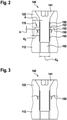
- FIG 2 is a schematic of a screw connection of the starter figure 1 shown using the example of a screw 140 in a more detailed view, in a position before complete screwing.
- part of the housing flange 122 and part of the relay housing 112 are shown, in each of which a recess 160 or 162 is provided.
- the recess 162 in the relay housing 112 is designed, for example, as a threaded bore, so that a thread 142 of the screw 140 can engage therein.
- the recess 160 in the housing flange 122 is designed, for example, as a through hole or bore (without thread) through which the screw 140 can be guided.
- relay housing 112 and housing flange 122 are somewhat spaced apart, with surfaces facing each other that will later, after complete screwing (as later in figure 3 shown), abut one another or are in contact with one another.
- This contact area is denoted by reference number 170 .
- the relay housing 112 in the contact area 170 is now a ring-shaped, at a distance d, around the recess 162, which has a diameter d A , running around elevation 150 with a height h and a thickness (or width) d E is formed, which above a level or flat area 152 rises.
- This elevation 150 can be introduced into the relay housing 112, for example, using a suitable stamping tool.
- the relay housing 112 and the housing flange 122 are pressed against one another, as is shown in figure 3 is shown.
- the elevation 150 is also pushed or pressed into the housing flange 122 or its surface, and depending on the shape of the elevation, it may also be cut into.
- the housing flange 122 is typically made of aluminum - the less rigid material is deformed by the pressure exerted by the elevation and forms a seal. In this way, water can no longer penetrate up to the thread or even into the thread or the thread.
Landscapes
- Engineering & Computer Science (AREA)
- General Engineering & Computer Science (AREA)
- Mechanical Engineering (AREA)
- Chemical & Material Sciences (AREA)
- Combustion & Propulsion (AREA)
- Connection Of Motors, Electrical Generators, Mechanical Devices, And The Like (AREA)
- Connection Of Plates (AREA)
Applications Claiming Priority (1)
| Application Number | Priority Date | Filing Date | Title |
|---|---|---|---|
| DE102020121081.7A DE102020121081A1 (de) | 2020-08-11 | 2020-08-11 | Starter für eine Brennkraftmaschine und Verfahren zu dessen Herstellung |
Publications (1)
| Publication Number | Publication Date |
|---|---|
| EP3954890A1 true EP3954890A1 (fr) | 2022-02-16 |
Family
ID=76374989
Family Applications (1)
| Application Number | Title | Priority Date | Filing Date |
|---|---|---|---|
| EP21178755.1A Withdrawn EP3954890A1 (fr) | 2020-08-11 | 2021-06-10 | Démarreur pour un moteur à combustion interne et son procédé de fabrication |
Country Status (3)
| Country | Link |
|---|---|
| EP (1) | EP3954890A1 (fr) |
| CN (1) | CN114076059A (fr) |
| DE (1) | DE102020121081A1 (fr) |
Citations (5)
| Publication number | Priority date | Publication date | Assignee | Title |
|---|---|---|---|---|
| ES2013243B3 (es) * | 1985-12-12 | 1990-05-01 | Communaute Europeenne De L'energie Atomique (Euratom) | Sistema de estanqueidad entre dos bridas metalicas. |
| US5322299A (en) * | 1988-05-27 | 1994-06-21 | Toshimitsu Terai | Metal gasket |
| US20080191421A1 (en) * | 2005-05-19 | 2008-08-14 | Valeo Equipements Electriques Moteur | Sealing by Material Deformation |
| US20170254311A1 (en) * | 2016-03-03 | 2017-09-07 | Johnson Electric S.A. | Engine, engine starter and housing assembly thereof |
| US10731491B2 (en) * | 2010-12-15 | 2020-08-04 | Mitsubishi Heavy Industries, Ltd. | Sealing structure for turbocharger housing |
Family Cites Families (15)
| Publication number | Priority date | Publication date | Assignee | Title |
|---|---|---|---|---|
| GB2120461B (en) | 1982-05-18 | 1986-01-29 | Paris & Du Rhone | Electric starter for an internal combustion engine |
| US4911316A (en) * | 1989-04-27 | 1990-03-27 | Cap Snap Co. | Plastic bottle cap sealing plural neck profiles |
| DE19748605B4 (de) | 1997-11-04 | 2013-12-19 | Robert Bosch Gmbh | Andrehvorrichtung für Brennkraftmaschinen |
| JP3884261B2 (ja) * | 2001-10-16 | 2007-02-21 | 澤藤電機株式会社 | スタータクラッチのシール構造 |
| DE102009038985A1 (de) | 2009-08-20 | 2011-02-24 | Rudolf Rafflenbeul Stahlwarenfabrik Gmbh & Co. Kg | Schraubverbindung |
| DE102010003823B4 (de) | 2010-04-09 | 2019-03-28 | Seg Automotive Germany Gmbh | Abdeckring für Startvorrichtung |
| DE102010038728A1 (de) | 2010-07-30 | 2012-02-02 | Hilti Aktiengesellschaft | Befestigungsvorrichtung |
| CN101956606A (zh) * | 2010-09-05 | 2011-01-26 | 张显荣 | 辐流式涡轮发动机 |
| CN202971895U (zh) * | 2012-11-20 | 2013-06-05 | 苏州旲烔机电科技有限公司 | 一种密封结构 |
| DE102013210444B4 (de) * | 2013-06-05 | 2022-01-05 | Seg Automotive Germany Gmbh | Startvorrichtung für eine Brennkraftmaschine |
| JP5816356B2 (ja) * | 2014-10-31 | 2015-11-18 | 三菱重工業株式会社 | ターボチャージャハウジングのシール構造 |
| CN205654861U (zh) * | 2016-05-30 | 2016-10-19 | 浙江万里扬股份有限公司 | 密封塞及工件的密封结构 |
| CN105864429A (zh) * | 2016-05-30 | 2016-08-17 | 浙江万里扬股份有限公司 | 密封塞及工件的密封结构 |
| CN207018618U (zh) * | 2016-08-15 | 2018-02-16 | 山东科瑞井控系统制造有限公司 | 一种用于阀门阀杆的密封填料 |
| CN209164552U (zh) * | 2018-08-06 | 2019-07-26 | 格特拉克(江西)传动系统有限公司 | 一种防止变速箱漏油的密封螺栓结构 |
-
2020
- 2020-08-11 DE DE102020121081.7A patent/DE102020121081A1/de not_active Withdrawn
-
2021
- 2021-04-02 CN CN202110361364.2A patent/CN114076059A/zh active Pending
- 2021-06-10 EP EP21178755.1A patent/EP3954890A1/fr not_active Withdrawn
Patent Citations (5)
| Publication number | Priority date | Publication date | Assignee | Title |
|---|---|---|---|---|
| ES2013243B3 (es) * | 1985-12-12 | 1990-05-01 | Communaute Europeenne De L'energie Atomique (Euratom) | Sistema de estanqueidad entre dos bridas metalicas. |
| US5322299A (en) * | 1988-05-27 | 1994-06-21 | Toshimitsu Terai | Metal gasket |
| US20080191421A1 (en) * | 2005-05-19 | 2008-08-14 | Valeo Equipements Electriques Moteur | Sealing by Material Deformation |
| US10731491B2 (en) * | 2010-12-15 | 2020-08-04 | Mitsubishi Heavy Industries, Ltd. | Sealing structure for turbocharger housing |
| US20170254311A1 (en) * | 2016-03-03 | 2017-09-07 | Johnson Electric S.A. | Engine, engine starter and housing assembly thereof |
Also Published As
| Publication number | Publication date |
|---|---|
| DE102020121081A1 (de) | 2022-02-17 |
| CN114076059A (zh) | 2022-02-22 |
Similar Documents
| Publication | Publication Date | Title |
|---|---|---|
| DE102008043488A1 (de) | Welle-Nabe-Bauteil sowie Verfahren zur Herstellung eines derartigen Bauteils | |
| DE2261446A1 (de) | Mit zaehnen versehenes kraftuebertragendes bauteil und verfahren zu seiner herstellung | |
| DE20010377U1 (de) | System zur Verbindung eines Anlasserzahnkranzes mit einem der Ausgangswelle eines Verbrennungsmotors verbundenen Träger | |
| DE19536027C2 (de) | Planetengetriebe-Geschwindigkeitsreduzierer und Herstellungsverfahren für einen Planetengetriebe-Haltestift für dasselbe | |
| EP2913561A1 (fr) | Système d'engrenage planétaire motorisé et procédé permettant de relier un moteur à un engrenage planétaire pour fabriquer un agencement moteur-engrenage planétaire | |
| DE10122249B4 (de) | Verfahren und Vorrichtung zum Bearbeiten von ringartigen Werkstücken | |
| EP2529103B1 (fr) | Procédé de liaison étanche à la haute pression d'au moins un corps en forme de plaque à un autre corps d'un injecteur de carburant et injecteur de carburant | |
| WO2006097194A1 (fr) | Procede pour produire une liaison articulee et liaison articulee | |
| DE102011102288B4 (de) | Vorrichtung und Verfahren zur Herstellung eines Stirnrads mit einer Schrägverzahnung | |
| DE102020121081A1 (de) | Starter für eine Brennkraftmaschine und Verfahren zu dessen Herstellung | |
| DE102006012031A1 (de) | Verfahren zur Herstellung einer Gelenkanbindung und Gelenkanbindung | |
| DE102009032083A1 (de) | Verfahren zum Einpressen eines hülsenförmigen Einpresselements in eine Fügeöffnung eines Bauteils | |
| DE102020200853A1 (de) | Verfahren zur umformenden Herstellung einer geschlossenen Hohlwelle | |
| WO1995020102A1 (fr) | Procede de fabrication d'un couvercle coule en metal leger et couvercle ainsi obtenu | |
| EP2042251A2 (fr) | Procédé de fabrication d'un boulon à bague d'arrêt et boulon à bague d'arrêt | |
| DE102016223820B4 (de) | Planetengetriebe mit einem gehäuseseitig stationär festgelegten Hohlrad, sowie Verfahren zur Fertigung eines Planetengetriebes | |
| EP2519756A1 (fr) | Étrier de frein pour un système de freinage de véhicule et procédé et dispositif de fabrication d'un étrier de frein | |
| DE10290270B3 (de) | Anbringung einer radialen Flachscheibe an einer Nabe, insbesondere für eine Kupplungsscheibe eines Kraftfahrzeugs | |
| EP3546812A1 (fr) | Système de composants hydrauliques doté d'un composant hydraulique fabriqué, au moins partiellement, de manière générative | |
| EP4397869A2 (fr) | Élément fonctionnel, composant d'assemblage et procédé de fabrication d'un composant d'assemblage | |
| DE102017200411A1 (de) | Befestigungsanordnung zur Befestigung mindestens eines Bauteils auf einer Welle | |
| DE102013101695A1 (de) | Kupplungsscheibe und Herstellungsverfahren | |
| DE102008061220B4 (de) | System zum Befestigen wenigstens einer weiteren Komponente an einer Kurbelwelle einer Brennkraftmaschine | |
| DE102013210899A1 (de) | Verfahren zur Herstellung eines gebauten Hohlventils | |
| DE102018124493A1 (de) | Gelenkgehäuse und Verfahren zur Herstellung eines Gelenkgehäuses |
Legal Events
| Date | Code | Title | Description |
|---|---|---|---|
| PUAI | Public reference made under article 153(3) epc to a published international application that has entered the european phase |
Free format text: ORIGINAL CODE: 0009012 |
|
| STAA | Information on the status of an ep patent application or granted ep patent |
Free format text: STATUS: THE APPLICATION HAS BEEN PUBLISHED |
|
| AK | Designated contracting states |
Kind code of ref document: A1 Designated state(s): AL AT BE BG CH CY CZ DE DK EE ES FI FR GB GR HR HU IE IS IT LI LT LU LV MC MK MT NL NO PL PT RO RS SE SI SK SM TR |
|
| STAA | Information on the status of an ep patent application or granted ep patent |
Free format text: STATUS: REQUEST FOR EXAMINATION WAS MADE |
|
| 17P | Request for examination filed |
Effective date: 20220328 |
|
| RBV | Designated contracting states (corrected) |
Designated state(s): AL AT BE BG CH CY CZ DE DK EE ES FI FR GB GR HR HU IE IS IT LI LT LU LV MC MK MT NL NO PL PT RO RS SE SI SK SM TR |
|
| STAA | Information on the status of an ep patent application or granted ep patent |
Free format text: STATUS: THE APPLICATION HAS BEEN WITHDRAWN |
|
| 18W | Application withdrawn |
Effective date: 20230222 |